48
Revision 01 Andreas Becker - 6/9/2011 1 of 48 Thermo Scientific CONFIDENTIAL Installation Protocol Dionex UltiMate™ 3000 Standard and RSLC HPLC Systems for Operation with Xcalibur and MS

Revision 01 Andreas Becker - 6/9/2011 1 of 48
Thermo Scientific CONFIDENTIAL
Installation Protocol
Dionex UltiMate™ 3000 Standard and RSLC HPLC Systems for Operation with Xcalibur and MS

Installation Protocol – Dionex UltiMate™ 3000 HPLC
(SD/RS) Systems for Operation with Xcalibur and MS
Revision 01 Andreas Becker - 6/9/2011 2 of 48
Thermo Scientific CONFIDENTIAL
Table of contents 1 Pre-installation ....................................................................................................................................... 4
1.1 Tools and accessory requirements ............................................................................................... 4
1.1.1 Tools ......................................................................................................................................... 4
1.1.2 Accessories, tubing, ferrules and nuts ...................................................................................... 6
2 Time Allocation ...................................................................................................................................... 7 2.1 Hardware Installation (1.5 – 2 hours) ........................................................................................... 7
2.2 System preparation and Installation Qualification (1.5 – 2 hours) ................................................ 7
2.3 Familiarization of system and software (1.5 – 2 hours) ................................................................ 7
2.4 Finalizing and closing ................................................................................................................... 7
3 System Configurations .......................................................................................................................... 8
3.1 Quaternary low pressure gradient systems .................................................................................. 8 3.2 Binary high pressure gradient systems ........................................................................................ 9
4 Installation ........................................................................................................................................... 10
4.1 Installation Workflow ................................................................................................................... 10
4.2 Unpacking ................................................................................................................................... 10
4.3 Stacking ...................................................................................................................................... 10 4.4 Installing DCMSLink ...................................................................................................................... 11
4.5 Installing the drainage system .................................................................................................... 12
4.5.1 Pump drainage ........................................................................................................................ 13
4.5.2 Autosampler drainage ............................................................................................................. 14
4.5.3 Routing across the table edge ................................................................................................ 14
4.6 Installing the communication cables ........................................................................................... 15 4.6.1 Installing the pump—SRD connection .................................................................................... 15
4.6.2 Installing the USB communication cables .............................................................................. 16
4.6.3 Installing the MS_Start cable .................................................................................................. 17
4.7 Installing Solvent Lines ............................................................................................................... 17
4.7.1 Solvent feed lines.................................................................................................................... 17
4.7.2 Autosampler wash fluid ........................................................................................................... 18 4.7.3 Rear seal wash system ........................................................................................................... 19
4.8 Capillary Connections ................................................................................................................. 19
4.8.1 Operating Viper Capillaries ..................................................................................................... 21
4.8.2 Connection on Autosampler Injection Valve ........................................................................... 21
5 System Preparation ............................................................................................................................. 23
5.1 Autosampler trays ....................................................................................................................... 23

Installation Protocol – Dionex UltiMate™ 3000 HPLC
(SD/RS) Systems for Operation with Xcalibur and MS
Revision 01 Andreas Becker - 6/9/2011 3 of 48
Thermo Scientific CONFIDENTIAL
5.2 Purging the system ..................................................................................................................... 23
6 DCMSLink (Chromeleon) Configuration ................................................................................................ 25
6.1 General ....................................................................................................................................... 25
6.2 Configuration of the system in Server Configuration .................................................................. 25 7 Software and Instrument Qualification (IQ) ......................................................................................... 32
7.1 Preparation ................................................................................................................................. 32
7.2 Running the Chromeleon IQ ....................................................................................................... 32
7.3 Running the Instrument IQ .......................................................................................................... 33
8 Software and Instruments OQ ............................................................................................................. 34
8.1 Chromeleon Software OQ .......................................................................................................... 34 8.2 Instruments OQ........................................................................................................................... 34
9 Familiarization ..................................................................................................................................... 35
9.1 Hardware familiarization ............................................................................................................. 35
9.1.1 General ................................................................................................................................... 35
9.1.2 Module-Specific Key Points .................................................................................................... 35
9.1.2.1 Degasser (external or integrated) ................................................................................... 35 9.1.2.2 Pump System .................................................................................................................. 35
9.1.2.3 Autosampler .................................................................................................................... 36
9.1.2.4 Thermostatted Column Compartment ............................................................................ 36
9.1.2.5 UV Detector incl. DAD and MWD ................................................................................... 37
9.2 DCMSLink Familiarization ............................................................................................................. 38 9.2.1 Software familiarization topics ................................................................................................ 38
9.2.2 Typical familiarization flow ...................................................................................................... 38
9.2.2.1 Server Icon ...................................................................................................................... 38
9.2.2.2 Server Configuration ....................................................................................................... 39
9.2.2.3 Manual Online System Control ....................................................................................... 40
9.2.2.4 Creating a Methods in Xcalibur ....................................................................................... 44 10 System Status Report (SSR) ........................................................................................................... 46
11 Administration tasks and closing ..................................................................................................... 48
12 Post-installation follow-up ................................................................................................................ 48

Installation Protocol – Dionex UltiMate™ 3000 HPLC
(SD/RS) Systems for Operation with Xcalibur and MS
Revision 01 Andreas Becker - 6/9/2011 4 of 48
Thermo Scientific CONFIDENTIAL
1 Pre-installation At least 3 working days prior to the installation, the engineer must check the sales acknowledgment and sales-to-service forms. They must also contact the sales rep, the technical specialist and the customer to check they have all the relevant information and that the customer is ready for the installation. This will enable the engineer to determine if parts are missing or ordered incorrectly and that all parts have arrived on site prior to the installation day. It will also ensure that the engineer is aware of any special requirements of the customer, the sales rep or the technical specialist.
1.1 Tools and accessory requirements
1.1.1 Tools The following tools must be available at hand to support the installation and apply instrument adjustments:
• Long nose pliers
• Haemostatic clamps/forceps
• Cable cutter
• Forceps/Tweezers (P/N 2140.0003)
• Spanners 1/4”x5/16” (P/N 6000.0051)
• Spanner 3/16” (P/N 6146.1231)
• Spanner 11x13 mm (P/N 2146.1053)
• Spanner 5.5 mm (P/N 6146.1225)
• Allen key 9/64” (P/N 6000.0053)
• Allen key 2.5 mm (P/N 6146.2625)
• Allen key 3 mm (P/N 6000.0050)
• 1 or 2 variable wrenches
• Philips screw drivers 2 sizes
• Flat-blade screw driver 2 sizes
• Torx T10 screw driver
• Torx T20 screw driver
• Cutting knife or blade
• Cutter/Scissors for stainless steel tubing
• Cutter for PEEK and PTFE tubing
• Seal extractor and alignment tool (P/N 6000.0046)
• Seal extractor and insertion tool for RS pumps (P/N 6040.7158 ?)
• Piston calibration tool for RS pumps (P/N 6040.7159 ?)
• Dionex menu pen (P/N 6300.0100)
• Mirror with flexible handle

Installation Protocol – Dionex UltiMate™ 3000 HPLC
(SD/RS) Systems for Operation with Xcalibur and MS
Revision 01 Andreas Becker - 6/9/2011 5 of 48
Thermo Scientific CONFIDENTIAL
Note: Wrenches, screwdrivers, Allen keys etc should be of good professional quality if they are purchased as part of a kit from tool supply stores.

Installation Protocol – Dionex UltiMate™ 3000 HPLC
(SD/RS) Systems for Operation with Xcalibur and MS
Revision 01 Andreas Becker - 6/9/2011 6 of 48
Thermo Scientific CONFIDENTIAL
1.1.2 Accessories, tubing, ferrules and nuts The accessories consider the stainless steel setup. Individual accessories depend on the configuration.
• Cable ties
• Adhesive cable clips
• 1x Drainage system for UltiMate 3000 (P/N 6040.0005)
• 1x Ferrules and Fittings kit (SR/FS-7) (P/N 6822.0012)
• 1x Ferrule and fitting kit Rheodyne (P/N 6822.0011)
• 5x Fitting crew (fingertight) PEEK (P/N 6266.0024)
• 1x Valco/Vici style ferrules (P/N 6720.0017)
• 1x Viper RS Kit (P/N 6040.2301)
• 1x Viper SD Kit (P/N 6040.2302)
• 1x Flex.-Cap., ID x L 0.13 x 65 mm Viper SST (P/N 6040.2307)
• 1x Flex.-Cap., ID x L 0.13 x 250 mm Viper SST (P/N 6040.2325)
• 1x Flex.-Cap., ID x L 0.13 x 350 mm Viper SST (P/N 6040.2335)
• 1x Flex.-Cap., ID x L 0.18 x 65 mm Viper SST (P/N 6040.2357)
• 1x Flex.-Cap., ID x L 0.18 x 450 mm Viper SST (P/N 6040.2365)
• 1x Flex.-Cap., ID x L 0.18 x 550 mm Viper SST (P/N 6040.2355)
• 5m PEEK capillary 0.50 mm/0.020” ID
• 5m PEEK capillary 0.25 mm/0.010” ID
• 5m PEEK capillary 0.18 mm/0.007” ID
• 5m PEEK capillary 0.13 mm/0.005” ID
• 1x Online degas wash kit for WPS/ACC (P/N 6820.2450)
• 3x USB cable (0.5 m, type A to type B, USB 2.0) (P/N 6720.8910)
• 1x Column see section Error! Reference source not found.
• 1x IQ standards see section Error! Reference source not found.
• Recommended UltiMate 3000 spare parts kits
Note: Some of these components are included in the instrument accessory kits. These additional supplies allow adjusting or modifying connections and optimize for chromatography.
Make sure that connections are short. The shortest connection should be from column to flow cell to avoid band broadening of already separated components.

Installation Protocol – Dionex UltiMate™ 3000 HPLC
(SD/RS) Systems for Operation with Xcalibur and MS
Revision 01 Andreas Becker - 6/9/2011 7 of 48
Thermo Scientific CONFIDENTIAL
2 Time Allocation Total installation time allocated 14 – 15 hours without travel and breaks.
2.1 Hardware Installation (1.5 – 2 hours) • Unpack system and place on bench (~ 30 minutes)
• Install PC and printer MS PC is used
• Connect cables and tubing (~ 30 minutes)
• Configure DCMSLink (~ 15 minutes)
2.2 System preparation and Installation Qualification (1.5 – 2 hours) • Mobile phase and column set up, initial system start up (~ 0.5 hours)
• System equilibration and IQ run(s) (~ 1.5 hour)
• Perform OQ/PQ if purchased wit system
2.3 Familiarization of system and software (1.5 – 2 hours) • Hardware familiarization (~ 2 hours)
• Software familiarization (~ 1 hours)
2.4 Finalizing and closing • Installation report and admin tasks (~ 45 minutes)
Installation Protocol – Dionex UltiMate™ 3000 HPLC
(SD/RS) Systems for Operation with Xcalibur and MS
Revision 01 Andreas Becker - 6/9/2011 8 of 48
Thermo Scientific CONFIDENTIAL
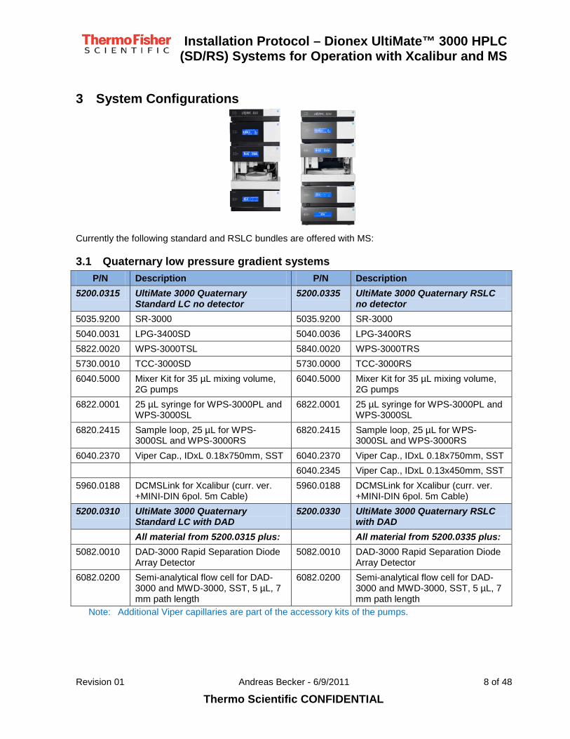
3 System Configurations
Currently the following standard and RSLC bundles are offered with MS:
3.1 Quaternary low pressure gradient systems P/N Description P/N Description
5200.0315 UltiMate 3000 Quaternary Standard LC no detector
5200.0335 UltiMate 3000 Quaternary RSLC no detector
5035.9200 SR-3000 5035.9200 SR-3000 5040.0031 LPG-3400SD 5040.0036 LPG-3400RS 5822.0020 WPS-3000TSL 5840.0020 WPS-3000TRS 5730.0010 TCC-3000SD 5730.0000 TCC-3000RS 6040.5000 Mixer Kit for 35 µL mixing volume,
2G pumps 6040.5000 Mixer Kit for 35 µL mixing volume,
2G pumps 6822.0001 25 µL syringe for WPS-3000PL and
WPS-3000SL 6822.0001 25 µL syringe for WPS-3000PL and
WPS-3000SL 6820.2415 Sample loop, 25 µL for WPS-
3000SL and WPS-3000RS 6820.2415 Sample loop, 25 µL for WPS-
3000SL and WPS-3000RS 6040.2370 Viper Cap., IDxL 0.18x750mm, SST 6040.2370 Viper Cap., IDxL 0.18x750mm, SST 6040.2345 Viper Cap., IDxL 0.13x450mm, SST 5960.0188 DCMSLink for Xcalibur (curr. ver.
+MINI-DIN 6pol. 5m Cable) 5960.0188 DCMSLink for Xcalibur (curr. ver.
+MINI-DIN 6pol. 5m Cable) 5200.0310 UltiMate 3000 Quaternary
Standard LC with DAD 5200.0330 UltiMate 3000 Quaternary RSLC
with DAD All material from 5200.0315 plus: All material from 5200.0335 plus: 5082.0010 DAD-3000 Rapid Separation Diode
Array Detector 5082.0010 DAD-3000 Rapid Separation Diode
Array Detector 6082.0200 Semi-analytical flow cell for DAD-
3000 and MWD-3000, SST, 5 µL, 7 mm path length
6082.0200 Semi-analytical flow cell for DAD-3000 and MWD-3000, SST, 5 µL, 7 mm path length
Note: Additional Viper capillaries are part of the accessory kits of the pumps.
Installation Protocol – Dionex UltiMate™ 3000 HPLC
(SD/RS) Systems for Operation with Xcalibur and MS
Revision 01 Andreas Becker - 6/9/2011 9 of 48
Thermo Scientific CONFIDENTIAL
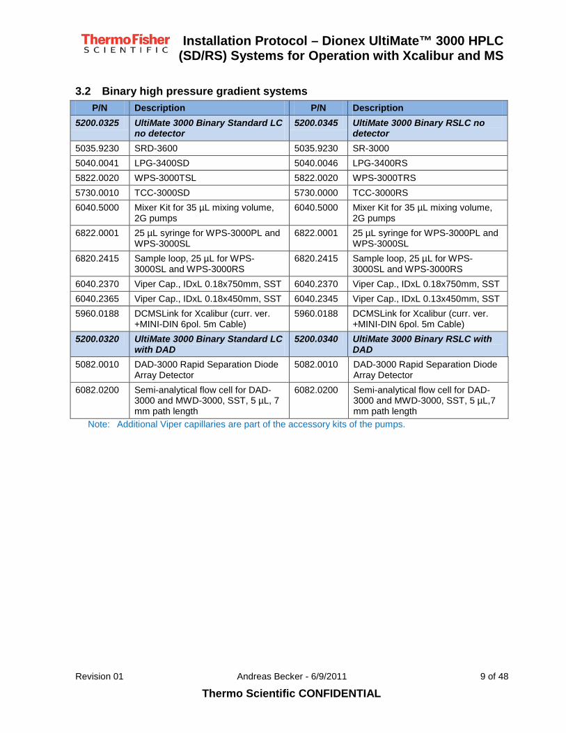
3.2 Binary high pressure gradient systems P/N Description P/N Description
5200.0325 UltiMate 3000 Binary Standard LC no detector
5200.0345 UltiMate 3000 Binary RSLC no detector
5035.9230 SRD-3600 5035.9230 SR-3000 5040.0041 LPG-3400SD 5040.0046 LPG-3400RS 5822.0020 WPS-3000TSL 5822.0020 WPS-3000TRS 5730.0010 TCC-3000SD 5730.0000 TCC-3000RS 6040.5000 Mixer Kit for 35 µL mixing volume,
2G pumps 6040.5000 Mixer Kit for 35 µL mixing volume,
2G pumps 6822.0001 25 µL syringe for WPS-3000PL and
WPS-3000SL 6822.0001 25 µL syringe for WPS-3000PL and
WPS-3000SL 6820.2415 Sample loop, 25 µL for WPS-
3000SL and WPS-3000RS 6820.2415 Sample loop, 25 µL for WPS-
3000SL and WPS-3000RS 6040.2370 Viper Cap., IDxL 0.18x750mm, SST 6040.2370 Viper Cap., IDxL 0.18x750mm, SST 6040.2365 Viper Cap., IDxL 0.18x450mm, SST 6040.2345 Viper Cap., IDxL 0.13x450mm, SST 5960.0188 DCMSLink for Xcalibur (curr. ver.
+MINI-DIN 6pol. 5m Cable) 5960.0188 DCMSLink for Xcalibur (curr. ver.
+MINI-DIN 6pol. 5m Cable) 5200.0320 UltiMate 3000 Binary Standard LC
with DAD 5200.0340 UltiMate 3000 Binary RSLC with
DAD 5082.0010 DAD-3000 Rapid Separation Diode
Array Detector 5082.0010 DAD-3000 Rapid Separation Diode
Array Detector 6082.0200 Semi-analytical flow cell for DAD-
3000 and MWD-3000, SST, 5 µL, 7 mm path length
6082.0200 Semi-analytical flow cell for DAD-3000 and MWD-3000, SST, 5 µL,7 mm path length
Note: Additional Viper capillaries are part of the accessory kits of the pumps.

Installation Protocol – Dionex UltiMate™ 3000 HPLC
(SD/RS) Systems for Operation with Xcalibur and MS
Revision 01 Andreas Becker - 6/9/2011 10 of 48
Thermo Scientific CONFIDENTIAL
4 Installation
4.1 Installation Workflow 1. Unbox the instruments
2. Check on external damages
3. Check completeness of accessories
4. Place the instruments on the bench
5. Plug in power cords and check if instruments power up
6. Arrange the instruments in the stack
7. Install DCMSLink on the MS PC
8. Connect communication lines
9. Add the drainage lines
10. Add the capillaries
11. Flush the system
12. Insert column for IQ
13. Equilibrate the column for IQ conditions
14. Perform the instruments IQ
15. Perform instruments OQ/PQ if purchased with system
16. Activate DCMSLink operation
17. Familiarize the customer
4.2 Unpacking • Check the boxes on damages
• Unpack the modules and place them on the bench
Attention: The autosampler is heavy and large. Ask for help to handle the autosampler.
• Check the accessories for completeness
• Unlock the optical bench of the detector by opening the orange knurled nuts (Figure 1).
Figure 1: Locking Screws on Detectors (Underneath Chassis)
• Power up the instruments to check if they were damaged during shipping.
4.3 Stacking The modules can be stacked in 2 different ways (top down):

Installation Protocol – Dionex UltiMate™ 3000 HPLC
(SD/RS) Systems for Operation with Xcalibur and MS
Revision 01 Andreas Becker - 6/9/2011 11 of 48
Thermo Scientific CONFIDENTIAL
• With detector:
▪ SRD/SR – LPG/HPG – WPS – TCC – Detector (Figure 2 left)
▪ SRD/SR – LPG/HPG – Detector – TCC – WPS (Figure 3 left)
• Without detector:
▪ SRD/SR – LPG/HPG – WPS – TCC (Figure 2 right)
▪ SRD/SR – LPG/HPG – TCC – WPS (Figure 3 right)
Depending on the MS the configuration with the detector in the middle of the can have a shorter capillary from detector to MS source inlet. In this case the capillary from pump to sampler will be longer.
•
Figure 2: UltiMate 3000 Stacks with Detector Left: Standard Stack, Right: Alternative Stack
Figure 3: UltiMate 3000 Stacks without Detector
Left: Standard Stack, Right: Alternative Stack
4.4 Installing DCMSLink Install a matching version of DCMSLink on the PC which has already Xcalibur installed. Use the default selections for installing DCMSLink.

Installation Protocol – Dionex UltiMate™ 3000 HPLC
(SD/RS) Systems for Operation with Xcalibur and MS
Revision 01 Andreas Becker - 6/9/2011 12 of 48
Thermo Scientific CONFIDENTIAL
Attention: If DCMSLink is installed before Xcalibur the necessary links and registrations are not created and the system is not functional.
4.5 Installing the drainage system The drainage tubing kit should be installed as explained in the associated instructions. The kit comes with tubing T-pieces, Y-pieces, elbows, unions and venting connectors and is part of the pump accessories. Additional drainage kits are available using P/N 6040.0005.
• Create 2 separate drainage paths:
▪ “Wet” path for SRD (SR), LPG/HPG pump, WPS
Note: The pumps use a unidirectional always active rear seal wash system which is drained through the drain port of the pump. It must be connected to the drainage system.
▪ “Dry” path for TCC and detector (DAD, VWD)
Attention: The drainage lines from pump and autosampler are always
• The purge outlet(s) from the purge unit(s) should be directed to waste using the supplied silicon tubing from the pump accessory kit. Route the tubing without obstruction into the T-piece of the drainage system as shown in
wet. Using a single drainage line for the system can trigger the humidity sensor or gas sensor in the TCC. The detector leak sensor might become submerged and trigger a leak alarm.
Figure 4 and Figure 5.
Note: The silicon tubing must be routed below the front panel otherwise the tubing will be pinched closing the panel.
• Install the lines close to the module body leaving very little space.
• For degasser, TCC and detectors use elbows as shown in Figure 4 and Figure 5.
• For autosampler use a combination of elbows and T-pieces as shown in Figure 4, Figure 5 and Figure 7.
• Install an elbow at the edge of the table in combination with a T-piece for venting as shown Figure 4 and Figure 5.
• Once crossing the table the lines may be joined using a Y-piece (Figure 8).

Installation Protocol – Dionex UltiMate™ 3000 HPLC
(SD/RS) Systems for Operation with Xcalibur and MS
Revision 01 Andreas Becker - 6/9/2011 13 of 48
Thermo Scientific CONFIDENTIAL
Figure 4: UltiMate 3000 Drainage System—Front Drainage
Left: Wet Components (blue), Right: Dry Components (orange)
Figure 5: UltiMate 3000 Drainage System—Rear Drainage
Left: Wet Components (blue), Right: Dry Components (orange)
4.5.1 Pump drainage Pumps use an always active rear seal wash system. This means in intervals wash fluid will be pushed out to the drain. This requires a good functioning drainage as shown in Figure 4 and Figure 5.
Attention: If the drainage system is not connected the waste from the rear seal wash will drip on the instruments and the table.
Connect the purge outlet(s) from the purge unit(s) to waste using the supplied silicon tubing from the pump accessory kit. Route the tubing without obstruction into the T-piece of the drainage system as shown in Figure 6.

Installation Protocol – Dionex UltiMate™ 3000 HPLC
(SD/RS) Systems for Operation with Xcalibur and MS
Revision 01 Andreas Becker - 6/9/2011 14 of 48
Thermo Scientific CONFIDENTIAL
Note: The silicon tubing must be routed below the front panel otherwise the tubing will be pinched closing the panel.
Figure 6: UltiMate 3000 Drainage System—Purge Drain
4.5.2 Autosampler drainage The autosampler waste tubing must drain easily avoiding any backup in the lines. The UltiMate 3000 drainage kit P/N 6040.0005 supplied with the pump contains all necessary components.
Note: Second generation UltiMate 3000 autosamplers e.g. WPS-3000TRS require 2 connections for wash and one connection for condensate (thermostatted version).
Figure 7: UltiMate 3000 Drainage System—Connecting the Autosampler
4.5.3 Routing across the table edge Using T- and L-pieces the drainage lines are routed over the table edge as shown in Figure 8. After crossing the table edge one can merge the 2 drainage lines using a Y-piece.
Note: the combination of T- and L-pieces reduce liquid backup and vents the tubing.

Installation Protocol – Dionex UltiMate™ 3000 HPLC
(SD/RS) Systems for Operation with Xcalibur and MS
Revision 01 Andreas Becker - 6/9/2011 15 of 48
Thermo Scientific CONFIDENTIAL
Figure 8: UltiMate 3000 Drainage System—Crossing Table Edge
4.6 Installing the communication cables All cables should be tidy and hidden behind the instruments as much as possible (Figure 9). Roll-up cables if necessary and use cable ties to fix them in position.
Figure 9: UltiMate 3000—Cable Connections and Routing
4.6.1 Installing the pump—SRD connection For units with SRD connect the 15-pin connection cable (P/N 6000.1006) from the SRD to the pump as shown in Figure 10. The cable is part of the SRD accessory kit.

Installation Protocol – Dionex UltiMate™ 3000 HPLC
(SD/RS) Systems for Operation with Xcalibur and MS
Revision 01 Andreas Becker - 6/9/2011 16 of 48
Thermo Scientific CONFIDENTIAL
Figure 10: UltiMate 3000—Control and Power Cable SRD to Pump
4.6.2 Installing the USB communication cables Note: Only 2G pumps and DAD/MWD have USB 2.0 hubs.
Always use the built-in USB hub on the rear of the Pump (USB 2.0) or DAD/MWD (USB 2.0) so that only one USB cable goes to the PC. For this purpose short USB cables are shipped with the modules. This ensures there are free USB ports on the PC at the end of the installation.
USB setup depends on the system configuration:
• Systems with DAD-3000(RS), MWD-3000(RS) connect through DAD-3000 or MWD-3000 (Figure 11 Left)
• Systems with SD/RS Pump without DAD or MWD connect through the pump (Figure 11 Right)
Attention: Do not use the USB ports on the autosampler to daisy chain other modules as they are USB 1.1!
Important: On no account the front USB ports on the computer must be used – this looks untidy and can block the customer from using USB sticks etc.
SRD
LPG/HPG
WPS
TCC
DAD/MWD
SRD Control
X
SRD
LPG/HPG
WPS
TCC
VWD/FLD
SRD Control
X
Figure 11: UltiMate 3000—USB Connection
Left: Systems with DAD/MWD, Right: Systems with VWD/FLD or no Detector

Installation Protocol – Dionex UltiMate™ 3000 HPLC
(SD/RS) Systems for Operation with Xcalibur and MS
Revision 01 Andreas Becker - 6/9/2011 17 of 48
Thermo Scientific CONFIDENTIAL
4.6.3 Installing the MS_Start cable The start of data acquisition needs to be synchronized with the injection of the LC system. The synchronization cable is part of the bundles and delivered as part of the DCMSLink software package (P/N 5960.0188). The cable is also available using P/N 6000.1004.
• Connect the mini-Din synchronization cable (Figure 12) to port 1 of the autosampler
• Connect the open ends as follows:
▪ Connect the white wire with label “Digital Output (GND)” to the ground, minus or low of the MS start input.
▪ Connect the brown wire with label “Digital Output” to the high or plus of the MS start input.
▪ Insulate all other wires with electric tape and use a cable tie to affix the remaining wires as coil to the cable.
Figure 12: UltiMate 3000—Synchronization Cable
Attention: In some cases the MS input might be classified as relay/contact closure input. This is not always correct. Therefore use the suggested wiring.
4.7 Installing Solvent Lines • Prepare the SRD/SR.
▪ Remove the Styrofoam insert form the solvent rack tray.
4.7.1 Solvent feed lines • Assemble the solvent filters (Figure 13)
Figure 13: UltiMate 3000—Solvent Filters
• Label the 1/8 solvent lines using the 1/8” markers with A, B, C, D (Figure 14) if not already factory prepared (LPG)

Installation Protocol – Dionex UltiMate™ 3000 HPLC
(SD/RS) Systems for Operation with Xcalibur and MS
Revision 01 Andreas Becker - 6/9/2011 18 of 48
Thermo Scientific CONFIDENTIAL
Figure 14: UltiMate 3000—Solvent Line Markers
• Connect the solvent feed lines to the external degasser (SRD) or to the internal degasser of the LPG pump if not already connected
Note: The upper row is out to the pump, the lower is in from the solvent reservoirs (Figure 15)
Figure 15: UltiMate 3000—Solvent Lines
• Push the tubing retainer guides over the solvent tubing.
• Insert the tubing and the guide into a bottle cap.
• Attach the solvent filter to the solvent line.
Attention: Do not operate the system without attached solvent filters.
• Close all open holes in the bottle cap with the stoppers from the SR/SRD accessory kit.
Important: Close all not used degasser channels with the yellow bolt stoppers which close the degasser ports on delivery
4.7.2 Autosampler wash fluid Bundles with binary HPG:
The bundles with HPG pumps include a SRD-3600. This leaves 2 degasser channels unused.
• Use one degasser channel and connect the channel to the syringe valve of the autosampler (Figure 16).
Figure 16: UltiMate 3000—Syringe Valve with Connected Wash Line
Bundles with quaternary LPG:
• Install the online degas wash kit T-ing off from a suitable feed line of the proportioning valve (Figure 17).
Out
In

Installation Protocol – Dionex UltiMate™ 3000 HPLC
(SD/RS) Systems for Operation with Xcalibur and MS
Revision 01 Andreas Becker - 6/9/2011 19 of 48
Thermo Scientific CONFIDENTIAL
• Connect the wash line to the syringe valve (Figure 16).
Figure 17: UltiMate 3000—Online Degas Wash Kit with Installed T
Important: Insufficiently degassed wash solvents will reduce the injector precision and linearity. Therefore use always degassed solvents as autosampler wash fluid.
4.7.3 Rear seal wash system • Make sure that the peristaltic tubing (Figure 18) is inserted below the lever of the peristaltic pump of
the rear seal wash system.
• Connect suitable length silicon tubing from the pump accessory kit to the peristaltic pump (Figure 18) of the pump rear seal wash system and route it to the small reservoir bottle of the pump accessory kit.
• Place the bottle in the solvent rack tray.
▪ Use tubing retainer guides to hold the tubing in place.
Figure 18: UltiMate 3000—Peristaltic Pump of Rear Seal Wash System
Attention: Never run the rear seal wash system dry.
4.8 Capillary Connections Capillary connections must be dead volume free as much as possible. Use Viper capillaries where ever possible. 3 Viper capillaries come with each pump accessory kit and are used for the standard setup (Figure 2 Left, Figure 3 Left). They have the contents as listed in Table 1.
Silicon Tubing

Installation Protocol – Dionex UltiMate™ 3000 HPLC
(SD/RS) Systems for Operation with Xcalibur and MS
Revision 01 Andreas Becker - 6/9/2011 20 of 48
Thermo Scientific CONFIDENTIAL
SD System RS System Length P/N ID P/N ID LPG Pumps 6040.2302 6040.2301 LPG→WPS 450 mm 6040.2365 0.18 mm/0.007” 6040.2365 0.18 mm/0.007” WPS→TCC 350 mm 6040.2375 0.18 mm/0.007” 6040.2335 0.13 mm/0.005” TCC→Detector 250 mm 6040.2385 0.18 mm/0.007” 6040.2325 0.13 mm/0.005” HPG Pumps 6040.2309 6040.2308 HPG→WPS 550 mm 6040.2355 0.18 mm/0.007” 6040.2355 0.18 mm/0.007” WPS→TCC 350 mm 6040.2375 0.18 mm/0.007” 6040.2335 0.13 mm/0.005” TCC→Detector 250 mm 6040.2385 0.18 mm/0.007” 6040.2325 0.13 mm/0.005”
Table 1: Viper Capillary Lengths for Standard Setup
Front Back
Figure 19: UltiMate 3000—Foam Insert Viper System Kit
Attention: The long capillary connecting pump to autosampler is located on the reverse side of the foam insert of the package!
The alternative setup (Figure 2 Right, Figure 3 Right) uses extra long capillaries from the pump to the sampler. These capillaries are part of the bundles. In this case the connections are listed in Table 2.
SD System RS System Length P/N ID P/N ID LPG Pumps LPG→WPS 750 mm 6040.2370 0.18 mm/0.007” 6040.2370 0.18 mm/0.007” WPS→TCC 450 mm 6040.2365 0.18 mm/0.007” 6040.2335 0.13 mm/0.005” TCC→Detector 250 mm 6040.2385 0.18 mm/0.007” 6040.2325 0.13 mm/0.005” HPG Pumps HPG→WPS 850 mm 6040.2370 0.18 mm/0.007” 6040.2370 0.18 mm/0.007” WPS→TCC 450 mm 6040.2365 0.18 mm/0.007” 6040.2345 0.13 mm/0.005” TCC→Detector 250 mm 6040.2385 0.18 mm/0.007” 6040.2325 0.13 mm/0.005”
Table 2: Viper Capillary Lengths for Alternative Setup
All high pressure tubing is routed through the chases in the instruments. Exceptions are the two stack setup and special applications. Use the precut tubing supplied with the instruments.

Installation Protocol – Dionex UltiMate™ 3000 HPLC
(SD/RS) Systems for Operation with Xcalibur and MS
Revision 01 Andreas Becker - 6/9/2011 21 of 48
Thermo Scientific CONFIDENTIAL
Important: Create only dead volume free connections. Otherwise the chromatography performance is sub-optimal and the Instruments IQ might fail.
4.8.1 Operating Viper Capillaries Viper Capillaries are finger-tight fittings with integrated flexible capillaries and a maximum pressure rating of 1200 bar/17,400 psi. Viper capillaries fit almost every 1/16” connection with 10-32 connectors.
When closing Viper fittings make sure that you do not over-tighten the fitting. Turn it by 45° (Figure 20) which normally closes the fitting. If it should leak continue to turn to a maximum of 90°.
The black nut can be removed once the capillary is mounted,
Figure 20: Viper Capillary—Turning Angles
• Connect the Viper capillaries as listed in Table 1 and Table 2
• Route the capillaries behind the front panels and use the capillary guides to lock the capillaries in place.
• Use the chase in the chassis to route the capillary from WPS to TCC
• When using a column preheater connect the longer capillary to the sampler injection valve guiding the capillary through the chase in the autosampler chassis (standard setup).
• When using a post column cooler connect the longer capillary to the inlet of the flow cell.
• Connect the outlet of the flow cell or the column to the source inlet of the MS using a 0.13 mm/0.005” ID PEEK capillary for RS systems and a 0.18 mm/0.007” ID PEEK capillary for SD systems.
Note: Viper capillaries of different length for the connection of the system to the MS source inlet are available. They are not part of the bundles.
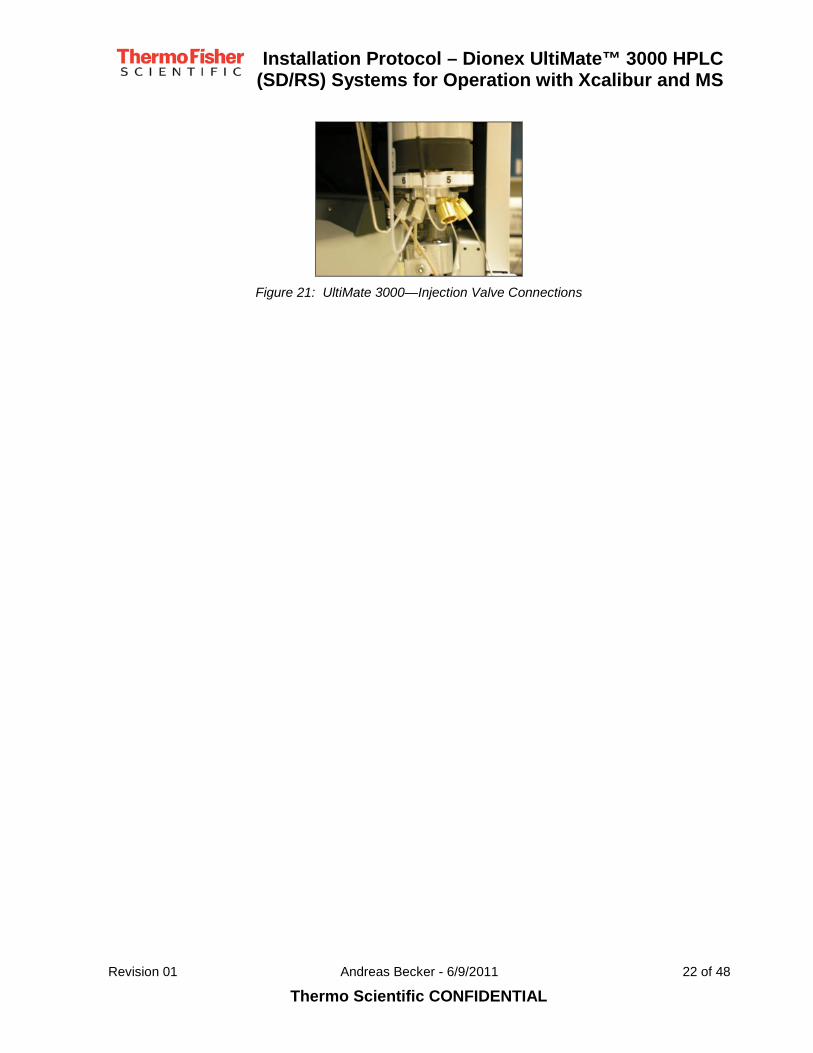
4.8.2 Connection on Autosampler Injection Valve • Connect the capillary from the pump to port 5 of the autosampler injection valve (Table 3, Figure 21).
• Connect the capillary to the column to port 4 of the injection valve (Table 3, Figure 21).
Port No Connect to… Port No Connect to… 1 Syringe/buffer loop 4 Column capillary 2 Injector waste capillary 5 Pump capillary 3 Needle seat capillary 6 Needle/sample loop
Table 3: UltiMate 3000—Injection Valve Connections
Installation Protocol – Dionex UltiMate™ 3000 HPLC
(SD/RS) Systems for Operation with Xcalibur and MS
Revision 01 Andreas Becker - 6/9/2011 22 of 48
Thermo Scientific CONFIDENTIAL
Figure 21: UltiMate 3000—Injection Valve Connections

Installation Protocol – Dionex UltiMate™ 3000 HPLC
(SD/RS) Systems for Operation with Xcalibur and MS
Revision 01 Andreas Becker - 6/9/2011 23 of 48
Thermo Scientific CONFIDENTIAL
5 System Preparation
5.1 Autosampler trays • Insert the trays into the autosampler carousel.
▪ The trays must rest on their guidance pins for correct positioning
• Make sure that the triangles for the wash vials are properly inserted.
Note: Incorrectly inserted trays can bend the drain tube for the condensate removal. The needle might hit the vial cap or rim when the tray is not properly inserted.
5.2 Purging the system All modules with mobile phase contact must be thoroughly flushed.
Note: The purging can be performed after DCMSLink has been configured.
• Purge the rear seal wash system with at least 5 mL of wash fluid.
Note: Use 5 – 10% of isopropanol or methanol in HPLC grade water.
• Purge Degasser
• Purge the degasser and the solvent feeding lines with at least 20 mL of Methanol before connecting any other mobile phase.
Note: Use compatible solvents when exchanging any solvent phase.
• Pump Purge Unit(s)
• Purge the pump outlet unit/purge valve unit with open purge valve with at least 5 mL of Methanol. Make sure that all air has been removed.
Note: Use the recommended flow rates for the installed pump.
• Purge the system using the purge through autosampler function.
Note: You might need to adjust purge flow rates and pressure limits if narrow ID capillaries e.g. 0.18 mm/0.007” or 0.12 mm/0.005” are installed.
• Prime Syringe
• Use the prime syringe routine to prime the syringe. Perform this at least 10 times.
Note: If an extra degasser channel is used the prime syringe routine needs to replace at least 2 mL of fluid. With a 100 µL syringe use prime syringe at least 25 times.
Important: The syringe must be bubble free. If the prime syringe routine does not clear the air from the syringe dismount the syringe and fill it with the selected wash fluid. Use the “change syringe” routine for this operation.
• Wash Buffer Loop
• After successful “prime syringe” execute the “Wash Buffer Loop” routine. Make sure that the fluid is exchanged at least 5 times.
• Wash the needle outside
• Wash the needle outside using the appropriate routine with 100 µL. Wash at least 3 times.
• Prepare the solvents for instruments IQ
▪ Prepare a mixture of 40% Methanol in HPLC grade water and purge the system.

Installation Protocol – Dionex UltiMate™ 3000 HPLC
(SD/RS) Systems for Operation with Xcalibur and MS
Revision 01 Andreas Becker - 6/9/2011 24 of 48
Thermo Scientific CONFIDENTIAL
▪ Equilibrate the column used for the IQ for about 10 minutes before use.

Installation Protocol – Dionex UltiMate™ 3000 HPLC
(SD/RS) Systems for Operation with Xcalibur and MS
Revision 01 Andreas Becker - 6/9/2011 25 of 48
Thermo Scientific CONFIDENTIAL
6 DCMSLink (Chromeleon) Configuration
6.1 General The DCMSLink configuration should be as clean and clear as possible to allow the operator immediate familiarity with the main functions. The HPLC system setup should be clearly recognizable.
The setup must include the following activities:
• Install Adobe Acrobat Reader directly from the Adobe Website if an Internet connection is available. This is required to read the troubleshooting guides.
Note: If the Internet is not available use the Adobe Reader setup from the Dionex Reference Library CD.
Important: In some companies the allowed Adobe Reader version is defined. In this case ask the customer for a copy.
• Create a folder “Server Configurations” in the Chromeleon folder e.g. “C:\DCMSLink”.
Note: This folder will keep a backup copy of the server configuration file.
6.2 Configuration of the system in Server Configuration • Open the Foundation Class “Instrument Configuration”
• Add DCMSLink to the configured devices (Figure 22).
Figure 22: DCMSLink—Adding DCMSLink to Instrument Configuration
• Select configure and the Chromeleon Server starts.

Installation Protocol – Dionex UltiMate™ 3000 HPLC
(SD/RS) Systems for Operation with Xcalibur and MS
Revision 01 Andreas Becker - 6/9/2011 26 of 48
Thermo Scientific CONFIDENTIAL
Figure 23: DCMSLink—Selecting Device Configuration
• Select device configuration (Figure 23) and the Chromeleon Server Configuration (Figure 24) opens.
Figure 24: DCMSLink—Chromeleon Server Configuration Window
• Control the configuration to ensure an empty configuration (Figure 24). In case devices are present:
▪ Remove any “Sharable Device” if present
▪ If visible in the configuration delete “Demo” and “<PC_Name>_1” timebases from server configuration and associated objects/files in the Browser.
• Install Dongle and Key Code (Figure 25) for running the IQ.

Installation Protocol – Dionex UltiMate™ 3000 HPLC
(SD/RS) Systems for Operation with Xcalibur and MS
Revision 01 Andreas Becker - 6/9/2011 27 of 48
Thermo Scientific CONFIDENTIAL
Figure 25: DCMSLink—Chromeleon Server Configuration—License
Note: The dongle and key code can be also inserted and activated after conditioning of the system before running the IQ.
• Create a new timebase with the name _UltiMate_3000_XXX. Replace XXX with an incremental number starting at 001 (Figure 26).
Note: This is only necessary if the system is installed in a network environment with more than one Chromeleon/DCMSLink station to ensure unique naming of timebases.
Attention: Do not check “Create Folder Structure for Your Data” (Figure 26).
Figure 26: DCMSLink—Chromeleon Server Configuration—Create Timebase
• Add device driver “Dionex DCMSLink for Xcalibur” to the timebase.
Note: Do not change names or activate the “Demo” mode”.
Figure 27: DCMSLink—Chromeleon Server Configuration—Xcalibur Driver
• Install the device driver for the pump.
▪ Adjust pressure unit as desired.
X
X

Installation Protocol – Dionex UltiMate™ 3000 HPLC
(SD/RS) Systems for Operation with Xcalibur and MS
Revision 01 Andreas Becker - 6/9/2011 28 of 48
Thermo Scientific CONFIDENTIAL
▪ When switching to psi from bar adjust the maximum as follows (Figure 28): 1034 bar → 15,000 psi 620 bar → 9,000 psi
Figure 28: DCMSLink—Chromeleon Server Configuration
Pump Pressure Limit Adjustment
• Install the device driver for the autosampler.
▪ In case of a LPG activate the synchronization with the pump (Figure 29).
Figure 29: DCMSLink—Chromeleon Server Configuration
Pump/Autosampler Synchronization
▪ Activate Relay_1 on the autosampler and name it MS_Start (Figure 30).

Installation Protocol – Dionex UltiMate™ 3000 HPLC
(SD/RS) Systems for Operation with Xcalibur and MS
Revision 01 Andreas Becker - 6/9/2011 29 of 48
Thermo Scientific CONFIDENTIAL
Figure 30: DCMSLink—Chromeleon Server Configuration
Autosampler MS_Start Relay
Attention: Do not activate or use Relay_4. It is reserved for automatic injector synchronization.
• Install the device driver for the TCC.
Note: When changing the pressure units on the pump to psi adjust the pressure unit (Figure 31) on the TCC.
Figure 31: DCMSLink—Chromeleon Server Configuration
TCC Pressure Unit Selection
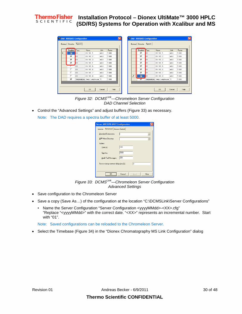
• Install the device driver for the detector if part of the bundle.
▪ Activate channels (Figure 32) as necessary (Default: 4 channels for DAD)
Installation Protocol – Dionex UltiMate™ 3000 HPLC
(SD/RS) Systems for Operation with Xcalibur and MS
Revision 01 Andreas Becker - 6/9/2011 30 of 48
Thermo Scientific CONFIDENTIAL
Figure 32: DCMSLink—Chromeleon Server Configuration
DAD Channel Selection
• Control the “Advanced Settings” and adjust buffers (Figure 33) as necessary.
Note: The DAD requires a spectra buffer of at least 5000.
Figure 33: DCMSLink—Chromeleon Server Configuration
Advanced Settings
• Save configuration to the Chromeleon Server
• Save a copy (Save As…) of the configuration at the location “C:\DCMSLink\Server Configurations”
▪ Name the Server Configuration “Server Configuration <yyyyMMdd>-<XX>.cfg” ”Replace “<yyyyMMdd>” with the correct date. “<XX>” represents an incremental number. Start with “01”.
Note: Saved configurations can be reloaded to the Chromeleon Server.
• Select the Timebase (Figure 34) in the “Dionex Chromatography MS Link Configuration” dialog

Installation Protocol – Dionex UltiMate™ 3000 HPLC
(SD/RS) Systems for Operation with Xcalibur and MS
Revision 01 Andreas Becker - 6/9/2011 31 of 48
Thermo Scientific CONFIDENTIAL
Figure 34: DCMSLink— Dionex Chromatography MS Link Configuration
Timebase Selection
• Select in the “Dionex Chromatography MS Link Configuration” dialog the choice for the event log window and the retention of data (Figure 35).
▪ Uncheck the option “Show event log window” if a separate event log window should be surpressed.
▪ Select the retention time for temporary data in the combo box “Delete temporary DCMSLink data”
Note: For troubleshooting purposes we recommend to select option “Older than 30 days”
Figure 35: DCMSLink— Dionex Chromatography MS Link Configuration
Options for Event Log Window and Temporary Data
• Select “Ok” and close the “Instrument Configuration” with “Done”.

Installation Protocol – Dionex UltiMate™ 3000 HPLC
(SD/RS) Systems for Operation with Xcalibur and MS
Revision 01 Andreas Becker - 6/9/2011 32 of 48
Thermo Scientific CONFIDENTIAL
7 Software and Instrument Qualification (IQ) In the IQ phase we need to perform a Chromeleon Software IQ followed by an Instruments IQ.
Attention: If you need to perform and Instruments OQ you must perform a Chromeleon Software OQ after the Chromeleon Software IQ and before the Instruments IQ.
7.1 Preparation • Install your dongle and enter your key code to unlock full Chromeleon.
• Prepare the mobile phase of 40% Methanol in water.
• Purge the system with the mobile phase.
• Mount the column for IQ.
• Set the column temperature to 25ºC.
• Equilibrate the column for 10 minutes at 1 mL/min.
• Perform a test injection of 5 µL with detection of 272 nm at 0.6 mL/min.
• Create a directory “zz_Service” in the timebase directory.
• Create a directory “IQ_Runs” in the timebase directory.
• Create the Instruments IQ runs from the templates on the Chromeleon CD in the directory just created: “<timebase name>/IQ_runs”.
▪ Name the IQ run collection (directory) “HPLC_IQ_<yyyyMMdd>-<XX>”. Replace “<yyyyMMdd>” with the correct date. “<XX>” represents an incremental number. Start with “01”.
Note: Run at this time the IQ to save time. All following steps can be executed while the IQ is running.
7.2 Running the Chromeleon IQ • Run a new Chromeleon IQ from the Qualification menu.
▪ Run “Check Installation”
▪ Run “System Information”
▪ Run “Check Datasource”.
Note: These three checks save valuable information that shows the computer and Chromeleon configurations at the time of installation.
• Store the log files in the DCMSLink IQ folder (DCMSLink\IQ) with their system proposed name and using “Save As” using the following nomenclature:
• IQReport_<yyyyMMdd>-<xx>.log SysInfo_<yyyyMMdd>-<xx>.log DBIQReport_<datasource name>_<yyyyMMdd>-<xx>.log
• Replace “<yyyyMMdd>” with the correct date. “<xx>” represents an incremental number. Start with “01”.

Installation Protocol – Dionex UltiMate™ 3000 HPLC
(SD/RS) Systems for Operation with Xcalibur and MS
Revision 01 Andreas Becker - 6/9/2011 33 of 48
Thermo Scientific CONFIDENTIAL
Figure 36: Chromeleon IQ selection dialog
7.3 Running the Instrument IQ • Load the prepared IQ sequences into the batch in the following order:
▪ IQ_Pump
▪ IQ_Inject_Det
▪ IQ_UV_Det
• Perform and observe warnings and errors.
• After the 0.6 mL/min run is completed in the sequence IQ_Pump review the data and shorten the runs in the sequences IQ_Inject_Det and IQ_UV_Det. Make sure that there is at least 0.5 minutes runtime left after the end peak mark of the last component (Caffeine).
• Make sure that Uracil and Caffeine are identified in all runs.
• Print the results of the IQ (3 printouts).
• Sign the results.
Note: Make sure to store the OQ results with the SSR

Installation Protocol – Dionex UltiMate™ 3000 HPLC
(SD/RS) Systems for Operation with Xcalibur and MS
Revision 01 Andreas Becker - 6/9/2011 34 of 48
Thermo Scientific CONFIDENTIAL
8 Software and Instruments OQ Attention: When performing an Instruments OQ you must run a Chromeleon Software OQ
prior to running the Instruments IQ and Instruments OQ. Otherwise obtained data are not valid.
8.1 Chromeleon Software OQ • Run the Chromeleon Software OQ from the Qualification manu
Note: The configuration will change automatically and the OQ is performed. Duration about 45 minutes
Note: Make sure to store the OQ results with the SSR
8.2 Instruments OQ • Prepare your system for the Instruments OQ by rinsing it with water and giving it ample time to warm-
up
• During this phase prepare the instruments
• Change the configuration to include the drivers for temperature and the temperature probe
• Store the configuration to the Chromeleon Server
• Store a copy of the configuration in the folder DCMSLink\Server Configurations using the following nomenclature:
Server Configuration Qualification_<yyyyMMdd>-<XX>”.
Replace “<yyyyMMdd>” with the correct date. “<XX>” represents an incremental number. Start with “01”.
• Prepare the standards
• Create the OQ templates from the Chromeleon CD
• Enter the information on standards in the RDF
• Run the OQ
• Print the results and sign them
Note: Make sure to store the OQ results with the SSR

Installation Protocol – Dionex UltiMate™ 3000 HPLC
(SD/RS) Systems for Operation with Xcalibur and MS
Revision 01 Andreas Becker - 6/9/2011 35 of 48
Thermo Scientific CONFIDENTIAL
9 Familiarization
9.1 Hardware familiarization
9.1.1 General The familiarization must enable the user to operate the system on his/her own. It is essential that all listed topics are covered. The user must perform the tasks like purging while maintenance is left mostly to theory. This hardware familiarization process includes handling of the commands and setting of variables through the TabSet panels and the F8-Command dialog in DCMSLink Panels. Specific DCMSLink topics are marked with (DCMSLink) or (DCMSLink/Chromeleon Xpress).
The familiarization topics must include:
• Instrument power up and power down procedures
• Flow path through instrument
• Drainage lines and routing
• Identification and function of each module
• Identification and function of key components of each module
• Purging of system
• Identification of consumable parts of each module and recommended replacement timeframe
• System care including cleaning and short and long-term storage procedures
• Rear seal wash system
Important: Rear Seal Wash System use is mandatory with all 3x00RS pumps
The familiarization topics are additionally covered in detail in the following HPLC instrument training class listed on the Dionex website in the training section:
• HPLC: UltiMate 3000 / Summit Operation, Maintenance, and Troubleshooting
9.1.2 Module-Specific Key Points
9.1.2.1 Degasser (external or integrated) • Exchange of solvent filters
• Maintenance of solvent filters
• Recommendation for long life time
• Location of leak sensor and how to dry after spillage
• Consumables/Spare part location in manual
9.1.2.2 Pump System • Rear seal-wash system and reservoir – function and maintenance
Important: With 2G pumps the rear seal wash cannot be deactivated!
• Purge unit with purge valve and pressure transducer
• Inline filter – function and maintenance
• Check valves exchange information in manual

Installation Protocol – Dionex UltiMate™ 3000 HPLC
(SD/RS) Systems for Operation with Xcalibur and MS
Revision 01 Andreas Becker - 6/9/2011 36 of 48
Thermo Scientific CONFIDENTIAL
• Seal exchange information in manual
Note: Make sure that the customer understands the importance of “Recommended Actions after Seal Change”
• Location of leak sensor and how to clean and dry after spillage
• Flow settings, gradient settings, pressure settings (DCMSLink/Chromeleon Xpress)
• Troubleshoot access on Home panel (DCMSLink/Chromeleon Xpress)
• Consumables/Spare part location in manual
9.1.2.3 Autosampler • Principle of inline split-loop operation
• Wash reservoir in the autosampler – function and maintenance (if used)
• T-in function of wash fluid (if used)
• Syringe maintenance—keep air bubble free (DCMSLink/Chromeleon Xpress→Wellness)
• Automated, unattended pump purge through autosampler (if customer activates option)
• Importance of unobstructed waste line
• Location of leak sensor and how to clean and dry after spillage
• Positioning the sample carousel segments on the autosampler keyboard and using DCMSLink/Chromeleon Xpress Panels
• Changing tray assignment if the user has purchased several different trays (DCMSLink/Chromeleon Xpress)
• Wash commands—Needle (internal/external), Buffer Loop, Prime Syringe (DCMSLink/Chromeleon Xpress)
• Needle wash commands in combination with Inject command (DCMSLink/Chromeleon Xpress)
• Injection parameters like speeds, delay times, puncture offset, AutoTrayShake (DCMSLink/Chromeleon Xpress→More Options)
• Consumables/Spare part location in manual
9.1.2.4 Thermostatted Column Compartment • Leak sensors—type (humidity and gas) and function
• Sensitivity settings for humidity and gas sensors (DCMSLink/Chromeleon Xpress)
• Column switching valves—function and maintenance (if installed)
• Column ID tags—function and usage (DCMSLink/Chromeleon Xpress)
• Column pre-heater if installed
• Post column cooler (RS model) if installed
• Temperature settings incl. ReadyTempDelta, EquilibrationTime (DCMSLink/Chromeleon Xpress)
• Operation of switching valves—assigning columns if applicable (DCMSLink/Chromeleon Xpress)
• Consumables/Spare part location in manual

Installation Protocol – Dionex UltiMate™ 3000 HPLC
(SD/RS) Systems for Operation with Xcalibur and MS
Revision 01 Andreas Becker - 6/9/2011 37 of 48
Thermo Scientific CONFIDENTIAL
9.1.2.5 UV Detector incl. DAD and MWD • For VWD setting of wavelength, data collection rate, time constant (DCMSLink/Chromeleon Xpress)
• For MWD setting of wavelength, reference, bandwidth, data collection rate, rise time, channel activation (DCMSLink/Chromeleon Xpress)
• For DAD setting of wavelength, reference, bandwidth, data collection rate, rise time, 3D-field, channel activation (DCMSLink/Chromeleon Xpress)
• Flow cell—function of identification chip, heat exchanger and maintenance
• Lamps—function of identification and tracking chip, expected lifetime and maintenance (exchange)
• Location of leak sensor and how to dry after spillage
• Consumables/Spare part location in manual

Installation Protocol – Dionex UltiMate™ 3000 HPLC
(SD/RS) Systems for Operation with Xcalibur and MS
Revision 01 Andreas Becker - 6/9/2011 38 of 48
Thermo Scientific CONFIDENTIAL
9.2 DCMSLink Familiarization In order to provide effective familiarization it is important that the customer experiences for themselves the operation of DCMSLink together with Xcalibur. Therefore it is expected that the customer operates the computer during the familiarization, not the service representative.
Important: The customer must operate the system and use DCMSLink with Xcalibur. The instructor must not operate the keyboard and mouse! This is only allowed in exceptional cases.
Note: The familiarization success is only possible if the customer operates DCMSLink, Xcalibur and the system!
It is recommended that the familiarization starts after starting the Instruments IQ with the preparation of the Installation/Training sequence.
9.2.1 Software familiarization topics The topics are covered in detail in the following Chromeleon training classes listed on the Dionex website in the training section:
• Chromeleon Level 1: An Introduction to Chromeleon
• Chromeleon Level 2: Next steps in Chromeleon
The familiarization topics must include:
• “Server Monitor”—function and meaning of different state colors
• “Server Configuration” accessed through Instrument Configuration—function and meaning of “Timebase”
Important: Do not explain how to configure the system. This is for information only!
• Panel TabSet through Chromeleon Xpress—function, operation and F8 commands
• Troubleshooting guide—module manuals (PDF)
• Program file—function, creation and editing
• System Status Report—function and operation—as troubleshooting tool
9.2.2 Typical familiarization flow The following list defines the typical flow through the familiarization of Chromeleon. At suitable moments the hardware is referenced e.g. during the online part.
1. Server Icon
2. Server Configuration
3. Online functions through Chromeleon Xpress and the Panels button
4. Creating Program through “Instrument Setup” in Xcalibur
5. Run sequence (Xcalibur)
6. Review data (Xcalibur)
7. System status report
9.2.2.1 Server Icon • Explain the various states of the Chromeleon Server icon in the taskbar (Figure 37)
▪ Crossed out red: Not active

Installation Protocol – Dionex UltiMate™ 3000 HPLC
(SD/RS) Systems for Operation with Xcalibur and MS
Revision 01 Andreas Becker - 6/9/2011 39 of 48
Thermo Scientific CONFIDENTIAL
▪ Yellow: Starting or stopping
▪ Green: Active method running or data acquisition on
▪ Turquoise: Reconfiguring
▪ Grey: Running idle
▪ Yellow/red: Chromeleon Server needs attention (waiting for user response)
Figure 37: Server Monitor—Taskbar Icon Status
• Explain the function “Start Server at System Start” (Figure 38) and activate if the customer whishes so.
Figure 38: Server Monitor—Configuration Dialog
Note: The Chromeleon Server starts automatically if opening the “Instrument Configuration” or Xcalibur. Activating the “Start Server at System Start” option avoids waiting delays.
9.2.2.2 Server Configuration • Show how to access the Server Configuration
▪ Close Xcalibur and all dependent windows
▪ Open Instrument Configuration
▪ Select DCMSLink icon in the “Configured Devices” pane
▪ Press configure
▪ The Dionex Chromatography MS Link Configuration dialog opens (Figure 39)

Installation Protocol – Dionex UltiMate™ 3000 HPLC
(SD/RS) Systems for Operation with Xcalibur and MS
Revision 01 Andreas Becker - 6/9/2011 40 of 48
Thermo Scientific CONFIDENTIAL
Figure 39: Dionex MS Link Configuration—Dialog
▪ Server Configuration opens
• Show how to re-import the saved configuration from the folder “DCMSLink\Server Configurations”
Note: This serves to show how to recover from a broken configuration.
• Save the configuration to the server
• Exit the “Server Configuration”
• Select the timebase In Dionex Chromatography MS Link Configuration (Figure 40)
Figure 40: Dionex MS Link Configuration—Timebase Selection
• Leave the Dionex Chromatography MS Link Configuration dialog with Ok
• Close the Instrument Configuration with “Done”
Attention: Do not show how to enter the Server Configuration through the Dionex→DCMSLink→Server Configuration
9.2.2.3 Manual Online System Control • Show how to access the Chromeleon Xpress panels through the Panels button in the Xcalibur
Roadmap
▪ Select Dionex Chromatography MS Link in the Status pane
▪ Select the now active Panels button

Installation Protocol – Dionex UltiMate™ 3000 HPLC
(SD/RS) Systems for Operation with Xcalibur and MS
Revision 01 Andreas Becker - 6/9/2011 41 of 48
Thermo Scientific CONFIDENTIAL
• Show how to access the Chromeleon Xpress panels through the Chromeleon desktop icon
• Show how to maneuver in the Panel Tabset (Figure 41)
▪ Explain the Take Control/Release Control feature
▪ Explain Connect All/Disconnect All
Figure 41: Chromeleon Xpress—Panel TabSet
• Show the pump panel (Figure 42)
▪ Show how to set a flow
▪ Show how to set a percentage
Figure 42: Chromeleon Xpress—Pump Panel
• Show how to purge the pumps
▪ Make sure that the operator understands that the selected percentages are used for purge
▪ Use the “More Options” to define purge flow rate and time (Figure 43)

Installation Protocol – Dionex UltiMate™ 3000 HPLC
(SD/RS) Systems for Operation with Xcalibur and MS
Revision 01 Andreas Becker - 6/9/2011 42 of 48
Thermo Scientific CONFIDENTIAL
Figure 43: Chromeleon Xpress—Pump Panel—More Options
• Explain the “Flow Ramp” feature
• Show how to access the “Undock Pistons/Dock Pistons” from the Service dialog (Figure 44)
Figure 44: Chromeleon Xpress—Pump Panel—Service
• Show the sampler panel (Figure 45)

Installation Protocol – Dionex UltiMate™ 3000 HPLC
(SD/RS) Systems for Operation with Xcalibur and MS
Revision 01 Andreas Becker - 6/9/2011 43 of 48
Thermo Scientific CONFIDENTIAL
Figure 45: Chromeleon Xpress—Sampler Panel
• Explain the wash functions:
▪ Prime Syringe
▪ Wash Buffer Loop
▪ Wash Needle Externally
• Show the “More Options” dialog for the sampler for adjusting speeds (Figure 46)
▪ Draw Speed and Draw Delay for the sample pickup
▪ Wash Speed and Waste Speed for wash operations
Figure 46: Chromeleon Xpress—Sampler Panel—More Options
• Show on the detector panel (Figure 47)

Installation Protocol – Dionex UltiMate™ 3000 HPLC
(SD/RS) Systems for Operation with Xcalibur and MS
Revision 01 Andreas Becker - 6/9/2011 44 of 48
Thermo Scientific CONFIDENTIAL
▪ Show how to start the lamps
▪ Show to set the wavelength
▪ Show how to start and top data acquisition to monitor the baseline
Figure 47: Chromeleon Xpress—Detector Panel
9.2.2.4 Creating a Methods in Xcalibur • Show Instrument Setup in Xcalibur (Figure 48)
Figure 48: Instrument Setup—Empty Method
• Select Dionex Chromatography Device
• Show how to create a method for the LC system
• On the Relay wizard page make sure to explain the MS_Start relay entries as shown in Figure 49
▪ MS_Start, State Off avoids accidental start of the MS data acquisition
▪ 0.000, MS_Start, State On, Duration 10.00 closes the relay for 10 seconds to start the MS data acquisition

Installation Protocol – Dionex UltiMate™ 3000 HPLC
(SD/RS) Systems for Operation with Xcalibur and MS
Revision 01 Andreas Becker - 6/9/2011 45 of 48
Thermo Scientific CONFIDENTIAL
Figure 49: Instrument Setup—Wizard Relay and State Dialog
• Explain how the device icons work
Attention: when using the device icon dialogs make sure that the customer checks the end times for gradient and data acquisition. Gradient and data acquisition should stop at the same time
• Explain the structure of the program and the synchronization with the Xcalibur acquisition server
▪ ReadyToRun = 1: Signals Xcalibur that LC is ready to go (equilibrated) (Figure 50)
Figure 50: Instrument Setup—Synchronization—ReadyToRun=1
▪ Wait StartRun: Waits for Xcalibur to signal continue with run (Figure 51)
Figure 51: Instrument Setup—Synchronization—Wait StartRun
▪ InjectResponse = 1: Signals Xcalibur that the injection was completed (Figure 52)
Figure 52: Instrument Setup—Synchronization—InjectResponse=1
▪ MS_Start.On Duration=10.00: Starts the MS per relay contact closure (Figure 53)

Installation Protocol – Dionex UltiMate™ 3000 HPLC
(SD/RS) Systems for Operation with Xcalibur and MS
Revision 01 Andreas Becker - 6/9/2011 46 of 48
Thermo Scientific CONFIDENTIAL
Figure 53: Instrument Setup—Synchronization—MS_Start=On
▪ InjectResponse = 0: Signals Xcalibur that the run was completed (Figure 54)
Figure 54: Instrument Setup—Synchronization—InjectResponse=0
• Save method
• Run method as part of a Xcalibur sequence
10 System Status Report (SSR) • Perform a System Status Report and show how to select audit trail and sequences to be forwarded to
support
• Access the System Status Report through Dionex→DCMSLink→System Status Report (Figure 55)
Figure 55: System Status Report—Start Dialog
• Select in Step 3 the data to backup

Installation Protocol – Dionex UltiMate™ 3000 HPLC
(SD/RS) Systems for Operation with Xcalibur and MS
Revision 01 Andreas Becker - 6/9/2011 47 of 48
Thermo Scientific CONFIDENTIAL
Figure 56: System Status Report—Object Selection
• Show how to ZIP the SSR for forwarding by e-mail
• Store a SSR with your documents for the installation

Installation Protocol – Dionex UltiMate™ 3000 HPLC
(SD/RS) Systems for Operation with Xcalibur and MS
Revision 01 Andreas Becker - 6/9/2011 48 of 48
Thermo Scientific CONFIDENTIAL
11 Administration tasks and closing As part of the familiarization, the customer should create a back up file using the System Status Report. This should include:
• Installation Qualification
• Setup Log
• Sequences and Directories—copy of installation sequence
• Server Configuration—most recent report
• Audit Trails—for the installation days
• Database Installation Qualification
Further activities:
• Activate the installation date in the modules (service mode)
• Store a backup of the server configuration in the folder “Server Configurations” (to be created) in the Chromeleon folder (C:\Chromel). Use as file name “Server Configuration <yyyyMMdd>-<xx>”. Replace “<yyyyMMdd>” with the correct date. “<xx>” represents an incremental number. Start with “01”. Upload this configuration to Oracle.
• Fill the IQ forms, zip the forms into a package and upload to Oracle
• Debrief the installation in Oracle—include the part numbers, model name and serial number. Add the closure notes
• Perfect/Imperfect Installation report with comments—upload to Oracle
• Run a charges report, e-mail to the customer and upload to Oracle
• Obtain customer sign off and upload to Oracle
This information will facilitate the troubleshooting of failed installations or customer problems.
12 Post-installation follow-up A maximum of 1 month after the installation, the local sales rep together with the relevant technical specialist will perform a post-installation follow-up visit. This will allow for checking that the system is installed to the customer’s satisfaction and that they are happy. It will also provide an opportunity for the customer to put questions to the specialist directly.


