85
1 ©2005 Nokia V1-Filename.ppt / yyyy-mm-dd/ Initials UMTS Radio Path and Transmission UMTS Radio Path and Transmission
| Date post: | 14-Apr-2018 |
| Category: |
Documents |
| Upload: | ebrahimsarani |
| View: | 217 times |
| Download: | 0 times |

7/30/2019 03_UMTS Radio Path and Transmission_emad
http://slidepdf.com/reader/full/03umts-radio-path-and-transmissionemad 1/85
1 © 2005 Nokia V1-Filename.ppt / yyyy-mm-dd/ Initials
UMTS Radio Path and TransmissionUMTS Radio Path and Transmission

7/30/2019 03_UMTS Radio Path and Transmission_emad
http://slidepdf.com/reader/full/03umts-radio-path-and-transmissionemad 2/85
2 © 2005 Nokia V1-Filename.ppt / yyyy-mm-dd/ Initials
Topics
• Quick review of air interface technologies
• The WCDMA (Air/Uu) interface and its properties• Radio resource management introduction (RRM RNC Functions)
• Briefly about issues related to network planning (optional topic)
• Nokia Smart Radio Concept (optional topic)
7/30/2019 03_UMTS Radio Path and Transmission_emad
http://slidepdf.com/reader/full/03umts-radio-path-and-transmissionemad 3/85
3 © 2005 Nokia V1-Filename.ppt / yyyy-mm-dd/ Initials
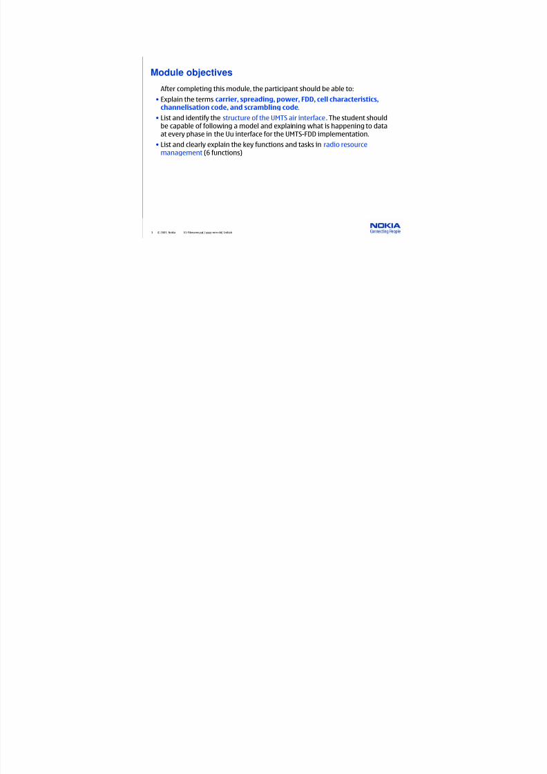
Module objectives
After completing this module, the participant should be able to:
• Explain the terms carrier, spreading, power, FDD, cell characteristics,
channelisation code, and scrambling code.
• List and identify the structure of the UMTS air interface. The student should
be capable of following a model and explaining what is happening to data
at every phase in the Uu interface for the UMTS-FDD implementation.
• List and clearly explain the key functions and tasks in radio resource
management (6 functions)

7/30/2019 03_UMTS Radio Path and Transmission_emad
http://slidepdf.com/reader/full/03umts-radio-path-and-transmissionemad 4/85
4 © 2005 Nokia V1-Filename.ppt / yyyy-mm-dd/ Initials
Power (P)
Frequency (f)
Time
Now, imagine if all the users sharedthe same frequency, at the sametime.
Radio path basics (review)
Frequency 2 - Channel 2
Frequency 1 - Channel 1
Frequency 3 - Channel 3
Frequency 4 - Channel 4
FDMA - Frequencies are allocated oneper user.
f1 - Ch 1 f1 - Ch 2 f1 - Ch 3 f1 - Ch 4
f2 - Ch 1 f2 - Ch 2 f2 - Ch 3 f2 - Ch 4
f3 - Ch 1 f3 - Ch 2 f3 - Ch 3 f3 - Ch 4
f4 - Ch 1 f4 - Ch 2 f4 - Ch 3 f4 - Ch 4
TDMA - Several users share the samefrequency, only divided by time.
f
t
How do you determine thedifferent users?
(spreading)codes
By allocating each channel a uniquecode, known as the spreading code.

7/30/2019 03_UMTS Radio Path and Transmission_emad
http://slidepdf.com/reader/full/03umts-radio-path-and-transmissionemad 5/85
5 © 2005 Nokia V1-Filename.ppt / yyyy-mm-dd/ Initials
Basic WCDMA theory (review)
Frequency Band
Spreading Factor
Power
WCDMAOriginating Bit Received Bit
+1
Power
FrequencyBand
FrequencyBand
Power
Power
FrequencyBand

7/30/2019 03_UMTS Radio Path and Transmission_emad
http://slidepdf.com/reader/full/03umts-radio-path-and-transmissionemad 6/85
6 © 2005 Nokia V1-Filename.ppt / yyyy-mm-dd/ Initials
Variable slices are allocated (review)
Frequency
5MHz
Power
Time
Users Separated byCodes
High bit rate user
Low bit rate user
7/30/2019 03_UMTS Radio Path and Transmission_emad
http://slidepdf.com/reader/full/03umts-radio-path-and-transmissionemad 7/85
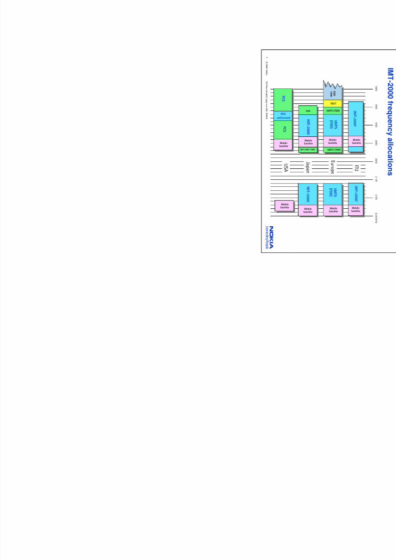
7
©
2 0 0 5 N ok i a
V 1 - F i l e n a m e . p p t / y y y y - mm- d d / I ni t i a l s
J a p a n
I MT -2 0 0 0
PHS
I MT -2 0 0 0
p
(FDD )
UM
1 8 0 0
UMT
(FDD )
U S A
PCSunlicensed
P C S
P C S
UMTS (TDD)IMT-2000 (TDD)
MSa
MSa
MobileSatellite
MobileSatellite
MobileSatellite
MobileSatellite

7/30/2019 03_UMTS Radio Path and Transmission_emad
http://slidepdf.com/reader/full/03umts-radio-path-and-transmissionemad 8/85
8 © 2005 Nokia V1-Filename.ppt / yyyy-mm-dd/ Initials
UMTS-FDD(Frequency Division Duplex)
GuardPeriod
f
t
Uplink
Downlink
Bandwidth 5MHz
Uplink Downlink
Bandwidth 5MHz
Separation 190MHzf
t Bandwidth 5MHz
UMTS-TDD(Time Division Duplex)

7/30/2019 03_UMTS Radio Path and Transmission_emad
http://slidepdf.com/reader/full/03umts-radio-path-and-transmissionemad 9/85
9 © 2005 Nokia V1-Filename.ppt / yyyy-mm-dd/ Initials
Basic WCDMA terminology
5 MHz
3.84 MHz
WCDMA Carrier (in one direction)
F r e q u e n c y
TimeDS = Direct Sequence
CDMA Sequencing Principles
7/30/2019 03_UMTS Radio Path and Transmission_emad
http://slidepdf.com/reader/full/03umts-radio-path-and-transmissionemad 10/85
10 © 2005 Nokia V1-Filename.ppt / yyyy-mm-dd/ Initials
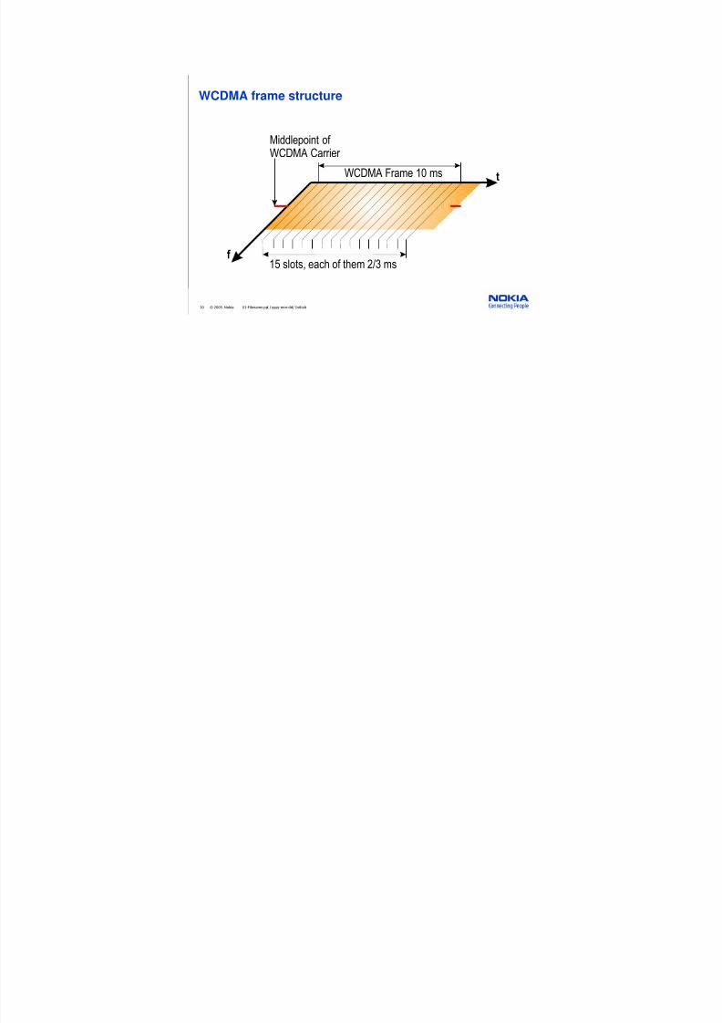
WCDMA frame structure
f
t
Middlepoint of WCDMA Carrier
WCDMA Frame 10 ms
15 slots, each of them 2/3 ms
7/30/2019 03_UMTS Radio Path and Transmission_emad
http://slidepdf.com/reader/full/03umts-radio-path-and-transmissionemad 11/85
11 © 2005 Nokia V1-Filename.ppt / yyyy-mm-dd/ Initials
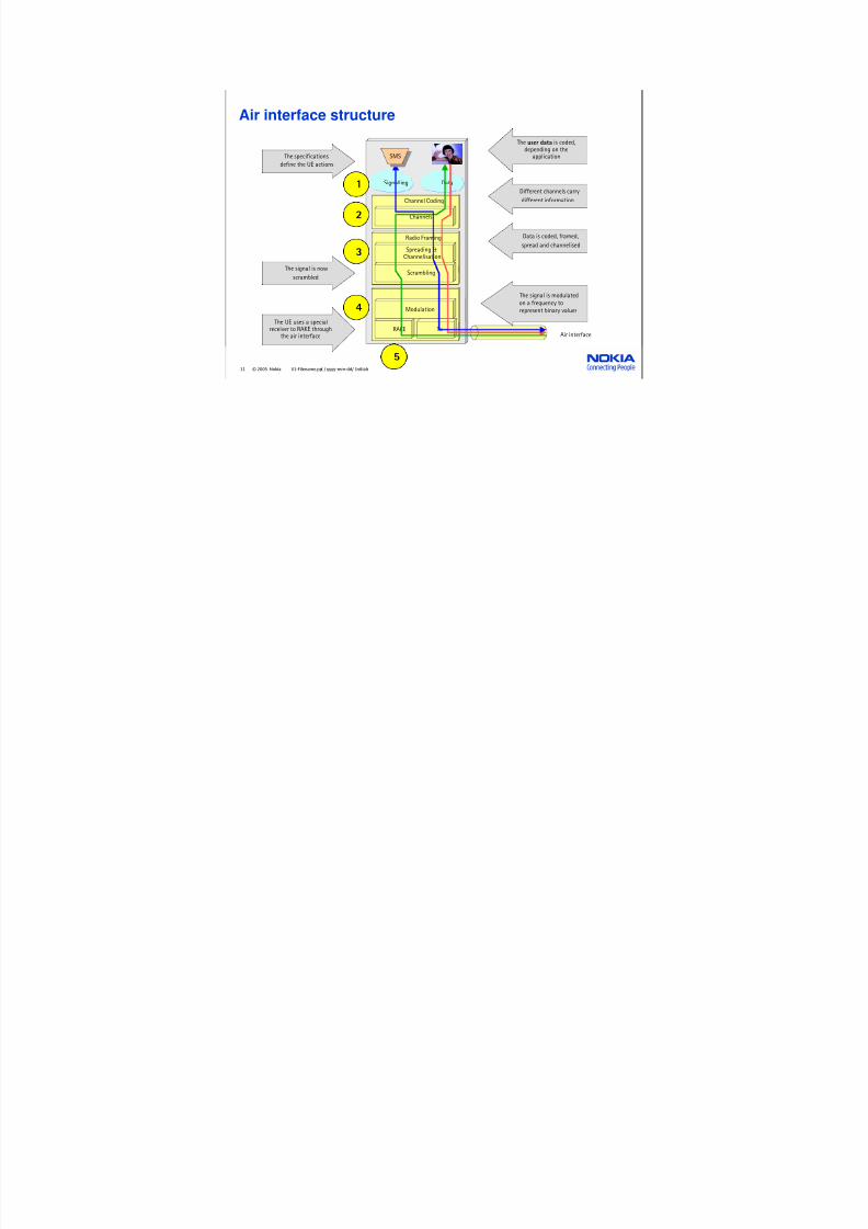
Air interface structure
Channel Coding
TxRAKE
Signalling Data
Channels
Radio Framing
Spreading &Channelisation
Scrambling
Modulation
Air interface
SMSSMS
define the UE actions
The user data is coded,depending on the
applicationThe specifications
1Different channels carry
different information
2
Data is coded, framed,
spread and channelised
The signal is now
scrambled
3
The signal is modulatedon a frequency torepresent binary values4
The UE uses a special
receiver to RAKE throughthe air interface
5
7/30/2019 03_UMTS Radio Path and Transmission_emad
http://slidepdf.com/reader/full/03umts-radio-path-and-transmissionemad 12/85
12 © 2005 Nokia V1-Filename.ppt / yyyy-mm-dd/ Initials
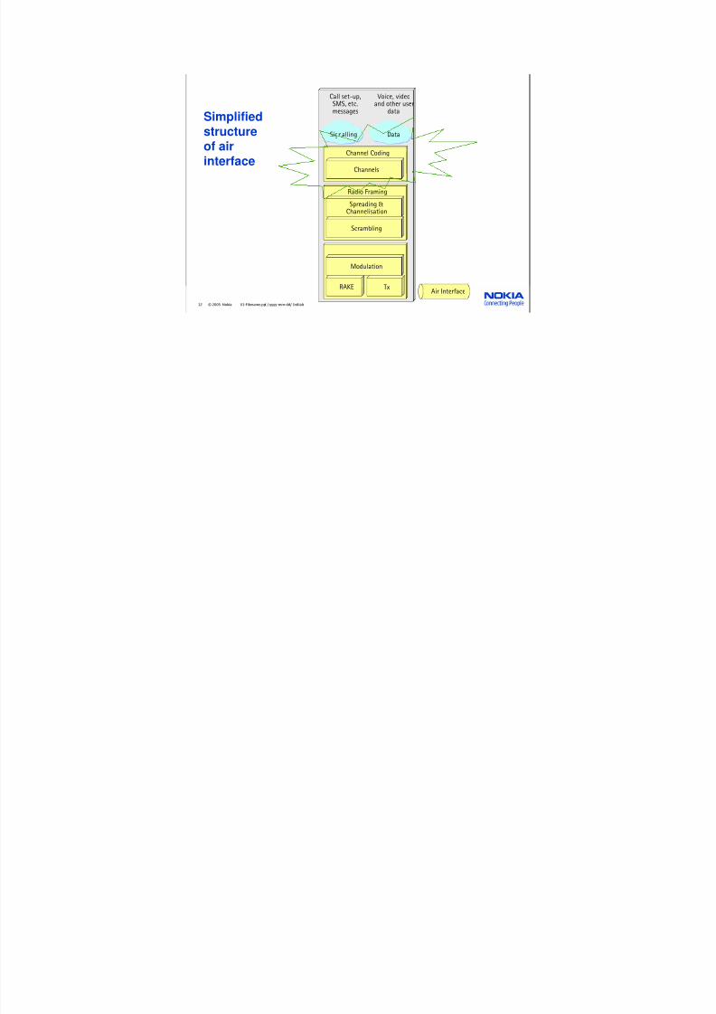
Simplified
structureof airinterface
Channel Coding
TxRAKEAir Interface
Signalling Data
Call set-up,SMS, etc.messages
Voice, videoand other user
data
Channels
Radio Framing
Spreading &Channelisation
Scrambling
Modulation

7/30/2019 03_UMTS Radio Path and Transmission_emad
http://slidepdf.com/reader/full/03umts-radio-path-and-transmissionemad 13/85
13 © 2005 Nokia V1-Filename.ppt / yyyy-mm-dd/ Initials
Channel coding, rate matching
• 1/2 and 1/3 rate convolutional channel coding and
turbo coding will be implemented.
• Rate matching is used to "fit" the data bit rate so that it
corresponds to the pre-defined fixed bit rates of theair interface. Also puncturing can be used.
Rate
Matching- Convolutional coding
- Interleaving
Baseband data (n kb/s)
- 30 kb/s
- 60 kb/s
- 120 kb/s
- 240 kb/s- 480 kb/s
- 960 kb/s

7/30/2019 03_UMTS Radio Path and Transmission_emad
http://slidepdf.com/reader/full/03umts-radio-path-and-transmissionemad 14/85
14 © 2005 Nokia V1-Filename.ppt / yyyy-mm-dd/ Initials
Simplified
structureof airinterface
Channel Coding
TxRAKEAir Interface
Signalling Data
Call set-up,SMS, etc.messages
Voice, videoand other user
data
Channels
Radio Framing
Spreading &Channelisation
Scrambling
Modulation

7/30/2019 03_UMTS Radio Path and Transmission_emad
http://slidepdf.com/reader/full/03umts-radio-path-and-transmissionemad 15/85
15 © 2005 Nokia V1-Filename.ppt / yyyy-mm-dd/ Initials
Channelisation and scrambling
SF=1 SF=2 SF=4
ch,1,0=(1)
ch,2,0=(1,1)
ch,2,1=(1,-1)
ch,4,0=(1,1, 1,1)
ch,4,1 =(1,1,-1,-1)
ch,4,2 =(1,-1,1,-1)
ch,4,3 =(1,-1,-1,1)
Data (Baseband, Channel Coded & Rate-Matched)
Spread and Combined with Channelisation Code
Data is Spread...
…by a certain factor. The channelisation codeis selected based upon how much the data is
spread
Data
Channelisation Code Scrambling Code
Downlink Example
Bit rate Chip rate Chip rate

7/30/2019 03_UMTS Radio Path and Transmission_emad
http://slidepdf.com/reader/full/03umts-radio-path-and-transmissionemad 16/85
16 © 2005 Nokia V1-Filename.ppt / yyyy-mm-dd/ Initials
Channelisation code tree
SF = 1 SF = 2 SF = 4
ch,1,0 = (1)
ch,2,0 = (1,1)
ch,2,1 = (1,-1)
ch,4,0 = (1,1,1,1)
ch,4,1 = (1,1,-1,-1)
ch,4,2 = (1,-1,1,-1)
ch,4,3 = (1,-1,-1,1)

7/30/2019 03_UMTS Radio Path and Transmission_emad
http://slidepdf.com/reader/full/03umts-radio-path-and-transmissionemad 17/85
17 © 2005 Nokia V1-Filename.ppt / yyyy-mm-dd/ Initials
Code
-1
Data xCode
Code
Data
+1
+1
+1
+1
+1
-1
-1
-1
-1
ChipChip
DespreadingDespreadingUu
WCDMA terminology - Chips & SymbolsSymbols (In this drawing, 1 Symbol = 8 Chips)
Rate
matchedbaseband
Data
Scrambling
7/30/2019 03_UMTS Radio Path and Transmission_emad
http://slidepdf.com/reader/full/03umts-radio-path-and-transmissionemad 18/85
18 © 2005 Nokia V1-Filename.ppt / yyyy-mm-dd/ Initials
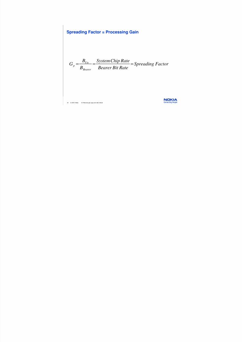
Spreading Factor = Processing Gain
Factor Spreading Rate Bit Bearer
RateChipSystem
B
BG
Bearer
Uu p ===

7/30/2019 03_UMTS Radio Path and Transmission_emad
http://slidepdf.com/reader/full/03umts-radio-path-and-transmissionemad 19/85
19 © 2005 Nokia V1-Filename.ppt / yyyy-mm-dd/ Initials
Where are codes used?
In the Uplink (UE → BTS),the user's data and
signalling information isseparated by
Channelisation Codes
datasignalling
In the Downlink (BTS→UE),cells are seperated byScrambling Codes
In the Uplink (UE → BTS),terminals are separated by
Scrambling Codes
In the Downlink (BTS → UE),user connections are separated
by Channelisation Codes
Dedicated User Channel
Channel Coding
TxRAKEAir interface
Signalling Data
Call set-up,SMSetc.messages
Voice,videoandotheruser data
Channels
Radio Framing
Spreading &
Channelisation
Scrambling
Modulation

7/30/2019 03_UMTS Radio Path and Transmission_emad
http://slidepdf.com/reader/full/03umts-radio-path-and-transmissionemad 20/85
20 © 2005 Nokia V1-Filename.ppt / yyyy-mm-dd/ Initials
Channelisation and scrambling codes
Ch annelisation code Scrambling cod e
Usage Uplink: Separation of physical data andcontrol channels from the same terminal
Downlink: Separation of downlinkdedicated user channels
Uplink: Separation of terminals
Downlink: Separation of sectors (cell)
Length Variable (depends on the user allocation) Fixed
Numberof codes
Depends on the spreading factor (SF) Uplink: Several millions
Downlink: 512

7/30/2019 03_UMTS Radio Path and Transmission_emad
http://slidepdf.com/reader/full/03umts-radio-path-and-transmissionemad 21/85
21 © 2005 Nokia V1-Filename.ppt / yyyy-mm-dd/ Initials
Modulation
Bit combinations in Radio Path:
'10'
135°
'00'
45°
'11'
225°
'01'
315°
Rx
TxQPSK
QPSK
BTSUE
DataData
7/30/2019 03_UMTS Radio Path and Transmission_emad
http://slidepdf.com/reader/full/03umts-radio-path-and-transmissionemad 22/85
22 © 2005 Nokia V1-Filename.ppt / yyyy-mm-dd/ Initials
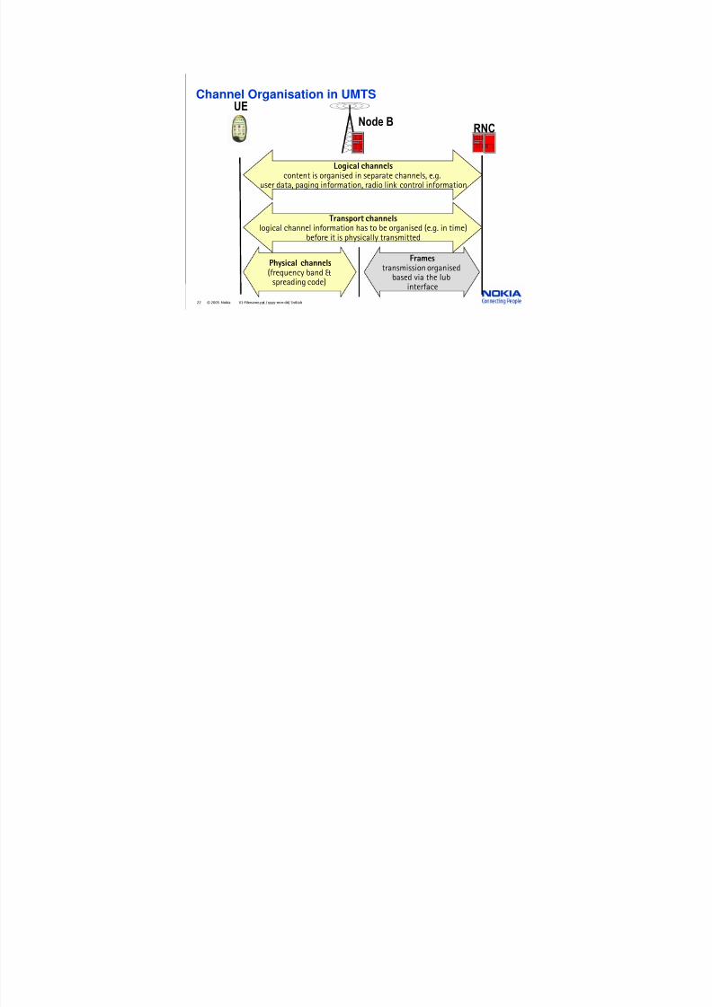
Channel Organisation in UMTSUE
Node BRNC
Logical channelscontent is organised in separate channels, e.g.
user data, paging information, radio link control information
Transport channelslogical channel information has to be organised (e.g. in time)
before it is physically transmitted
Physical channels
(frequency band &spreading code)
Frames
transmission organisedbased via the Iubinterface

7/30/2019 03_UMTS Radio Path and Transmission_emad
http://slidepdf.com/reader/full/03umts-radio-path-and-transmissionemad 23/85
23 © 2005 Nokia V1-Filename.ppt / yyyy-mm-dd/ Initials
Downlink Uplink
LogicalChannels
Channels DS-WCDMA-FDD
BCCH PCCH DCCH DTCH CCCH DTCH DCCH
TransportChannels
BCH PCH DCH DCHRACH CPCH
PhysicalChannels
CCPCH-1 CCPCH-2 PRACH DPDCH DPCCH
CCCH CTCH
FACH DSCH
PDSCH PCPCHDPCH(DPDCH+DPCCH)
CCPCH-1 : Primary Common Control Physical Channel
CCPCH-2 : Secondary Common Control Physical Channel
DPDCH/DPCCH : Dedicated Physical Data/Control Channel
PDSCH : Physical Downlink Shared Channel
PRACH : Physical Random Access Channel
PCPCH : Physical Common Packet Channel

7/30/2019 03_UMTS Radio Path and Transmission_emad
http://slidepdf.com/reader/full/03umts-radio-path-and-transmissionemad 24/85
24 © 2005 Nokia V1-Filename.ppt / yyyy-mm-dd/ Initials
Downlink
LogicalChannels
Channels DS-WCDMA-FDD
TransportChannels
PhysicalChannels
SCH CPICH PICHAICH
SCH : Synchronisation Channel
CPICH : Common Pilot ChannelAICH : Acquisition Indication Channel
PICH : Paging Indication Channel
No Logical andTransport Channels

7/30/2019 03_UMTS Radio Path and Transmission_emad
http://slidepdf.com/reader/full/03umts-radio-path-and-transmissionemad 25/85
25 © 2005 Nokia V1-Filename.ppt / yyyy-mm-dd/ Initials
FDD-mode: Logical and Transport Channel DL
BCCH
Broadcast Control Channel,(system information)
PCCHPaging Control Channel(paging & notification)
CCCHCommon Control Channel(control information withoutRRC connection)
DCCHDedicated Control Channel(power control, TFI, etc.)
DTCHDedicated Traffic Channel(user data)
Logical Channels (content)
BCH
Broadcast Channel,
PCHPaging Channel
FACHForward Access Channel
DSCHDownlink Shared Channel
DCHDedicated Channel
Transport Channels
dedicated
transportchannels
commontransportchannels

7/30/2019 03_UMTS Radio Path and Transmission_emad
http://slidepdf.com/reader/full/03umts-radio-path-and-transmissionemad 26/85
26 © 2005 Nokia V1-Filename.ppt / yyyy-mm-dd/ Initials
FDD-mode: Logical and Transport Channel UL
CCCH
Common Control Channel(control information withoutRRC connection)
DCCHDedicated Control Channel(power control, TFI, etc.)
DTCHDedicated Traffic Channel(user data)
Logical Channels (content)
RACH
Random AccessChannel
CPCHCommon Packet Channel
DCHDedicated Channel
Transport Channels
dedicatedtransportchannels
commontransportchannels

7/30/2019 03_UMTS Radio Path and Transmission_emad
http://slidepdf.com/reader/full/03umts-radio-path-and-transmissionemad 27/85
27 © 2005 Nokia V1-Filename.ppt / yyyy-mm-dd/ Initials
FDD-mode: Physical Channel DL
how to getsynchronised
?
SCH-1Primary Synchronisation Channel(chip & timeslot synchronisation)
SCH-2Secondary Synchronisation Channel(frame and scrambling class synchronisation)
CPICHCommon Pilot Channel(for power measurement and scramblingcode determination; channelisation code
is CCH,256,0)
Node B
RNC

7/30/2019 03_UMTS Radio Path and Transmission_emad
http://slidepdf.com/reader/full/03umts-radio-path-and-transmissionemad 28/85
28 © 2005 Nokia V1-Filename.ppt / yyyy-mm-dd/ Initials
Scrambling Code group into Code sets
Primary Scrambling Code
Secondary Scrambling Code #1
Secondary Scrambling Code #2
Secondary Scrambling Code #15
Channelisation Code Set (256 Codes)
Channelisation Code Set (256 Codes)
Channelisation Code Set (256 Codes)
Channelisation Code Set (256 Codes)
Primary Scrambling Code
Secondary Scrambling Code #1
Secondary Scrambling Code #2
Secondary Scrambling Code #15
Channelisation Code Set (256 Codes)
Channelisation Code Set (256 Codes)
Channelisation Code Set (256 Codes)
Channelisation Code Set (256 Codes)
- 512 Code Sets x 16 Scrambling Codes = 8192 Codes numbered from 0 ... 8191 available

7/30/2019 03_UMTS Radio Path and Transmission_emad
http://slidepdf.com/reader/full/03umts-radio-path-and-transmissionemad 29/85
29 © 2005 Nokia V1-Filename.ppt / yyyy-mm-dd/ Initials
FDD-mode: Physical Channel DL
how to getsystem
information?
Node B
CCPCH-1Primary Common Control Physical Channel(UE knows scrambling code from CPICH,channelisation code always CCH,256,1,system information)
CCPCH-2Secondary Common Control Physical Channel(for paging and notification; channelisationcode delivered as system information)
BCCH
RNC
BCH
PCCH PCH
CCCH
DCCH
DTCH
FACH

7/30/2019 03_UMTS Radio Path and Transmission_emad
http://slidepdf.com/reader/full/03umts-radio-path-and-transmissionemad 30/85
30 © 2005 Nokia V1-Filename.ppt / yyyy-mm-dd/ Initials
FDD-mode: Physical Channel
how to makethe firstcontact?
Node B
RNC
P RA C H Pre am b le
P RA C H Pre am b l
e
P RA C H Me s s age P
ar t
AI C H
CCCH RACHDCCHDTCH
PRACHPhysical RandomAccess Channel
AICHAcquisition IndicationChannel

7/30/2019 03_UMTS Radio Path and Transmission_emad
http://slidepdf.com/reader/full/03umts-radio-path-and-transmissionemad 31/85
31 © 2005 Nokia V1-Filename.ppt / yyyy-mm-dd/ Initials
Example of channel usage
UplinkDownlink
LogicalChannels
TransportChannels
PhysicalChannels
SCH BCCH PCCH CCCH DCCH DTCH CCCH DTCH DCCH
SCH BCH PCH FACH DCH DCHRACH CPCH
SCH1/2CCPCH-1 CCPCH-2 DPCH(DPDCH+DPCCH)
PRACH DPDCH DPCCH PCPCH
CTCH
Signalling to Terminal
User Data to Terminal
SMSSMS
Signalling to Network
User Data to Network
DSCH
PDSCH
7/30/2019 03_UMTS Radio Path and Transmission_emad
http://slidepdf.com/reader/full/03umts-radio-path-and-transmissionemad 32/85
32 © 2005 Nokia V1-Filename.ppt / yyyy-mm-dd/ Initials
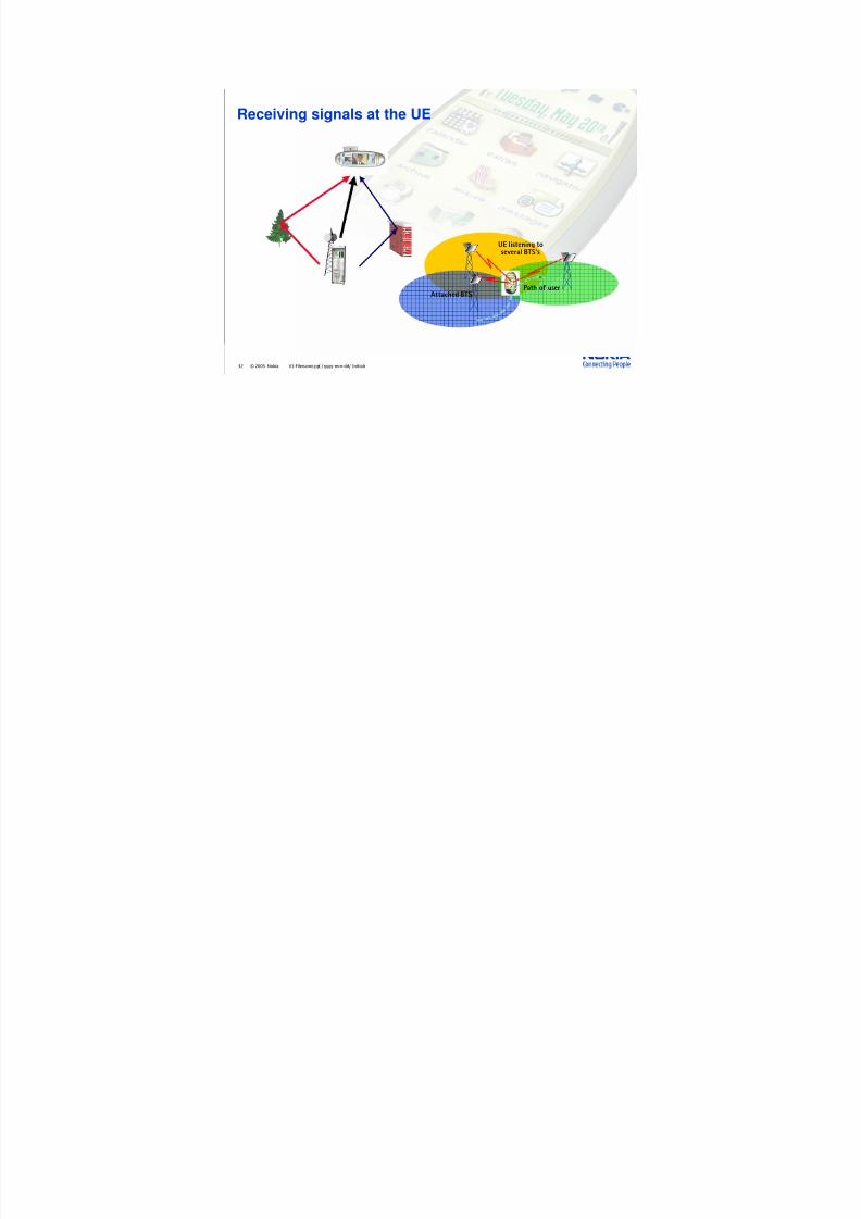
Receiving signals at the UE
UE listening toseveral BTS's
Attached BTSPath of user

7/30/2019 03_UMTS Radio Path and Transmission_emad
http://slidepdf.com/reader/full/03umts-radio-path-and-transmissionemad 33/85
33 © 2005 Nokia V1-Filename.ppt / yyyy-mm-dd/ Initials
Simplified diagram of the RAKE Receiver
D e
l a yCode used
for theconnection
Rx
Output
Finger
t
Cell-x
Cell-x
Cell-x
Cell-y
Rx
Rx
Rx
Finger
Finger
Finger
D e
l a y
D e
l a y

7/30/2019 03_UMTS Radio Path and Transmission_emad
http://slidepdf.com/reader/full/03umts-radio-path-and-transmissionemad 34/85
34 © 2005 Nokia V1-Filename.ppt / yyyy-mm-dd/ Initials
Radio Resource Control (RRC) states
Idlemode
Connected Mode
Cell DCH
URA PCH
Cell PCH
Cell FACH

7/30/2019 03_UMTS Radio Path and Transmission_emad
http://slidepdf.com/reader/full/03umts-radio-path-and-transmissionemad 35/85
35 © 2005 Nokia V1-Filename.ppt / yyyy-mm-dd/ Initials
Management of channels in RRC
RLC RLC RLC
RRCsignalling
CS RAB(speech)
PS RAB(data)
MAC
L1
Iub/IurMAC forCommonChannels
• Segmentation• Retransmission across the air• Ciphering of NRT data• Buffering
Iu
2. Transport channels
3. Physical Channel(s) (Radio)
1. Logical Channels
RLC: Radio Link Control
MAC: Medium Access Control
• Selection of the data to be insertedin the Radio Frame
• Selection of common or dedicated channels• Multiplexing of logical channels into
same transport channels• Ciphering for RT

7/30/2019 03_UMTS Radio Path and Transmission_emad
http://slidepdf.com/reader/full/03umts-radio-path-and-transmissionemad 36/85
36 © 2005 Nokia V1-Filename.ppt / yyyy-mm-dd/ Initials
Radio Resource Management
Iub Iu
Iur
In
te
rface
Un
its
In
te
rface
Un
its
(Wideband)Switching
ControlUnits
Radio
Resource
Management
O&MInterface
to/from Network
Management
to/fromotherRNCs
to/fromCore
Network
to/fromthe BSs

7/30/2019 03_UMTS Radio Path and Transmission_emad
http://slidepdf.com/reader/full/03umts-radio-path-and-transmissionemad 37/85
37 © 2005 Nokia V1-Filename.ppt/ yyyy-mm-dd/ Initials
Radio Resource Management
• It is responsible for utilisation of the air interface
• It is needed to guarantee QoS, to maintain the planned coverage area andto offer high capacity.
• Management of Traffic
Network Based function
(Cell Resource Management)
• Load Control (LC)
• Admission Control (AC)
• Packet Scheduler (PS)
• Resource Manager (RM)
Connection Based function
• Power Control (PC)
• Handover Control (HC) PC
HC connectionbasedfunctions
LC
AC networkbasedfunctions
PS
RM
PC
HC connectionbasedfunctions
LC
AC networkbasedfunctions
PS
RM
Trainer comment
•The RRM deals with means of establishing, maintaining, balancing, modifying, and releasing the basic
means of communication on the radio interface and through the RAN.
•It provides procedures during system information broadcasting, connection establishment, connected
session, and connection release session.
•It is needed to guarantee QoS, to maintain the planned coverage area and to offer high capacity.
•In addition, the RRM performs actions to prevent the overloading of the radio network according to the
interference measurements.
•To be more specific, we can list the following functions:
⇒ Cell resource management functions (LC, AC, PS, RM)
⇒ HC and PC

7/30/2019 03_UMTS Radio Path and Transmission_emad
http://slidepdf.com/reader/full/03umts-radio-path-and-transmissionemad 38/85
38 © 2005 Nokia V1-Filename.ppt / yyyy-mm-dd/ Initials
RRM Function in Brief
1. Admission Control• Admit or reject request of Radio Access Bearer (RAB)
2. Load Control• Ensure the system is not overloaded and remains stable
3. Packet Scheduler• Ensure availability of air interface and select Transport Channel for packet
data
4. Power Control• Keep interference level minimum and maintain QoS
5. Resource Manager• Code management for Channelisation code and Scrambling code
6. Handover Control• Handover action

7/30/2019 03_UMTS Radio Path and Transmission_emad
http://slidepdf.com/reader/full/03umts-radio-path-and-transmissionemad 39/85
39 © 2005 Nokia V1-Filename.ppt / yyyy-mm-dd/ Initials
1. Admission Control (AC)
Radio Access Bearersin Uu Interface
U u I n t e r f a
c e B a n
d w i d t h
SIR - Allowed RangeAdmission Control
Interference Margin (dB) and Load Factor
0
5
10
15
20
25
0 0.1 0.2 0.3 0.4 0.5 0.6 0.7 0.8 0.9 1
Load Factor
I n t e r f e r e n c e M a r g i n ( d B )
−
⋅=
Factor Load Log I
_1
110
Admit or reject request of Radio Access Bearer (RAB)

7/30/2019 03_UMTS Radio Path and Transmission_emad
http://slidepdf.com/reader/full/03umts-radio-path-and-transmissionemad 40/85
40 © 2005 Nokia V1-Filename.ppt / yyyy-mm-dd/ Initials
TRHO_threshold
Prx_target
Prx_target_BS
UL interference power
Load
Planned load area
Marginal load area
planned uplinkinterference power
Defines the limit (the first UL overload threshold) for theUL interference power, after which the BTSBTS starts its loadcontrol actions to prevent overload.
Prx_offset
Uplink Admission Control
Prx_target defines the optimal operating point of the cell interfernce power, up to which theAdmission Control of the RNC can operate.

7/30/2019 03_UMTS Radio Path and Transmission_emad
http://slidepdf.com/reader/full/03umts-radio-path-and-transmissionemad 41/85
41 © 2005 Nokia V1-Filename.ppt / yyyy-mm-dd/ Initials
• The purpose of load control is to optimise the capacity of a cell andprevent overload situation.
• Load control consists of Admission Control (AC) and Packet Scheduler(PS) algorithms, and Load Control (LC), which updates the load status of
the cell based on resource measurements and estimations provided by
AC and PS.
LC
AC
PSNRT load
Load changeinfo
Load status
2. Load Control (LC)

7/30/2019 03_UMTS Radio Path and Transmission_emad
http://slidepdf.com/reader/full/03umts-radio-path-and-transmissionemad 42/85
42 © 2005 Nokia V1-Filename.ppt / yyyy-mm-dd/ Initials
The restriction of CDMA system is interference
The more transmission poweris required to achieve certainquality
The further awayusers are connected
The more usersthat are connected
Finally the capacity is filled

7/30/2019 03_UMTS Radio Path and Transmission_emad
http://slidepdf.com/reader/full/03umts-radio-path-and-transmissionemad 43/85
43 © 2005 Nokia V1-Filename.ppt / yyyy-mm-dd/ Initials
• The traffic can be divided into two groups:
Real Time (RT) and Non-Real Time (NRT).
• Thus some slide of capacity must be reserved for the RT traffic for mobilitypurposes all the time. The proportion between RT and NRT traffic varies allthe time.
Capacity
Time
Overload
Load Target
Overload Margin
P o w e r
Estimated capacity forNRT traffic.
Measured load causedby non-controllable load

7/30/2019 03_UMTS Radio Path and Transmission_emad
http://slidepdf.com/reader/full/03umts-radio-path-and-transmissionemad 44/85
44 © 2005 Nokia V1-Filename.ppt / yyyy-mm-dd/ Initials
Load Control Description
• Load Control's (LC) task is to make sure that the system is not overloaded
and remains stable.
• LC can be divided into two functions:
1. Preventive control = Guards the system from overload.
2. Overload control = Returns the system from a overload state to normalstate in a fast and controlled way.
• Since interference is the main resource criteria for CDMA, the load controlmeasures:
• UL total received wideband interference power
• DL total transmission power
• Periodically under one RNC on cell basis.
• Radio Resource Manager (RRM) acts according to these measurements andparameters set by Radio Network Planning.
7/30/2019 03_UMTS Radio Path and Transmission_emad
http://slidepdf.com/reader/full/03umts-radio-path-and-transmissionemad 45/85
45 © 2005 Nokia V1-Filename.ppt / yyyy-mm-dd/ Initials
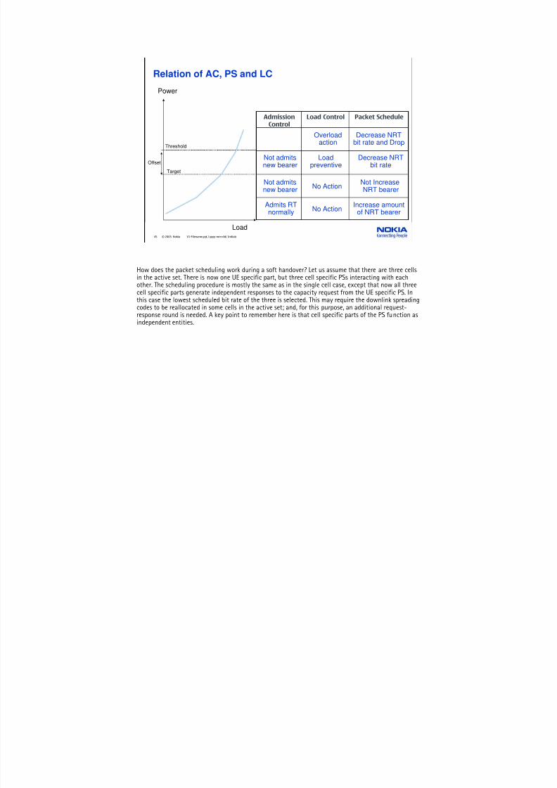
Relation of AC, PS and LC
Load
Power
Threshold
Offset
Target
Packet ScheduleLoad ControlAdmissionControl
No ActionAdmits RT
normally
Increase amount
of NRT bearer
No ActionNot admitsnew bearer
Not IncreaseNRT bearer
Not admitsnew bearer
Loadpreventive
Decrease NRTbit rate
Overloadaction
Decrease NRTbit rate and Drop
How does the packet scheduling work during a soft handover? Let us assume that there are three cellsin the active set. There is now one UE specific part, but three cell specific PSs interacting with eachother. The scheduling procedure is mostly the same as in the single cell case, except that now all threecell specific parts generate independent responses to the capacity request from the UE specific PS. Inthis case the lowest scheduled bit rate of the three is selected. This may require the downlink spreadingcodes to be reallocated in some cells in the active set; and, for this purpose, an additional request-response round is needed. A key point to remember here is that cell specific parts of the PS function asindependent entities.

7/30/2019 03_UMTS Radio Path and Transmission_emad
http://slidepdf.com/reader/full/03umts-radio-path-and-transmissionemad 46/85
46 © 2005 Nokia V1-Filename.ppt / yyyy-mm-dd/ Initials
• Ensure availability of Air Interface capacity for all packet data users
• Select which transport channel is used for the packet data transmission
• ( I.e. Common Ch, Dedicated Ch, Shared Ch, Common Packet Ch)
3. Packet Scheduler (PS)
time
packet service session
packet call
reading time
packet size packet arrival interval

7/30/2019 03_UMTS Radio Path and Transmission_emad
http://slidepdf.com/reader/full/03umts-radio-path-and-transmissionemad 47/85
47 © 2005 Nokia V1-Filename.ppt / yyyy-mm-dd/ Initials
4. Power control (PC)
Open Loop Power Control (Initial Access)
Closed Loop Power Control
Outer Loop Power Control
BTS RNC
Without Power Control system,Cell capacity will decrease.
1. UL Open loop PC ( For Initial Tx power of UE)
2. Fast closed loop PC (DCH; DL →UE, UL →BTS)
3. Outer loop PC (DCH; DL →UE, UL →RNC)

7/30/2019 03_UMTS Radio Path and Transmission_emad
http://slidepdf.com/reader/full/03umts-radio-path-and-transmissionemad 48/85
48 © 2005 Nokia V1-Filename.ppt / yyyy-mm-dd/ Initials
UL Outer Loop PC during Soft Handover

7/30/2019 03_UMTS Radio Path and Transmission_emad
http://slidepdf.com/reader/full/03umts-radio-path-and-transmissionemad 49/85
49 © 2005 Nokia V1-Filename.ppt / yyyy-mm-dd/ Initials
CELL 1 CELL 3CELL 2
1. Scrambling codes
2. Channelisation codes
full code set / cell
SUBS2SUBS1
5. Resource Management (RM)
Assign UL Code
to UE
Cell ID
allocated by
O&M
Scrambling
Code
Assign UL Code
to UE
- Allocate Code
- Re-arrange of
the code tree
Channelisation
Code
UplinkDownlink
Code Management

7/30/2019 03_UMTS Radio Path and Transmission_emad
http://slidepdf.com/reader/full/03umts-radio-path-and-transmissionemad 50/85
50 © 2005 Nokia V1-Filename.ppt / yyyy-mm-dd/ Initials
Tree of Channelisation Code in downlink
• Hierarchical selection of short codes from a "code tree" to maintain
orthogonality.
• Several long scrambling codes can be used within one sector to avoidshortage of short codes.
C1(0) = [ 1 ]
C2(0) = [ 1 1 ]
C2(1) = [ 1 0 ]
C4(0) = [ 1 1 1 1 ]
C4(1) = [ 1 1 0 0 ]
C4(2) = [ 1 0 1 0 ]
C4(3) = [ 1 0 0 1 ]
C8(0) = [ 1 1 1 1 1 1 1 1 ]
C8(1) = [ 1 1 1 1 0 0 0 0 ]
. . .
. . .
Spreading factor:
SF = 1 SF = 2 SF = 4 SF = 8
C8(2) = [ 1 1 0 0 1 1 0 0 ]
C8(3) = [ 1 1 0 0 0 0 1 1]
. . .
. . .
C8(4) = [ 1 0 1 0 1 0 1 0 ]
C8(5) = [ 1 0 1 0 0 1 0 1 ]
. . .
. . .
C8(6) = [ 1 0 0 1 1 0 0 1 ]
C8(7) = [ 1 0 0 1 0 1 1 0 ]
. . .
. . .
Example of code allocation

7/30/2019 03_UMTS Radio Path and Transmission_emad
http://slidepdf.com/reader/full/03umts-radio-path-and-transmissionemad 51/85
51 © 2005 Nokia V1-Filename.ppt / yyyy-mm-dd/ Initials
6. Handover Control (HC)
Soft Handover
4
Hard/Inter-Frequency Handover
Softer Handover
Inter-SystemHandover
BTSBTS
Frequency f1
Frequency f1
BTSBTS
Frequency f1 Frequency f2
BTSBTS
WCDMA GSM900/1800
BTSSector 1
f1
Sector 2
f1
Sector 3f1
Multipath Signal
through Sector 1
Multipath Signal through Sector 3
BTSBTS
Frequency f1
Frequency f1
RNC RNCIur
Iu b Iub

7/30/2019 03_UMTS Radio Path and Transmission_emad
http://slidepdf.com/reader/full/03umts-radio-path-and-transmissionemad 52/85
52 © 2005 Nokia V1-Filename.ppt / yyyy-mm-dd/ Initials
Handover types
CNRNC
MSCBSC
GSM900/1800GSM900/1800
WCDMA FDDWCDMA FDD
Inter-SystemInter-System
Intra-SystemIntra-System
WCDMA TDDWCDMA TDD
Inter-SystemInter-System
7/30/2019 03_UMTS Radio Path and Transmission_emad
http://slidepdf.com/reader/full/03umts-radio-path-and-transmissionemad 53/85
53 © 2005 Nokia V1-Filename.ppt / yyyy-mm-dd/ Initials
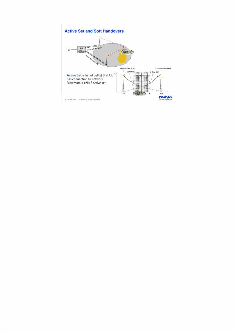
Active Set and Soft Handovers
CNRNC
f r a m e r e l i a b i l i t y i n f o
f ra m e r e l ia b i l
i t y i n f o
frameselection / duplication
BS1 BS2
Soft handover window
P2) Add BS2
1) Connection to BS1
3) Drop BS1
4) Connection to BS2
Active Set is list of cell(s) that UEhas connection to network.Maximum 3 cells / active set

7/30/2019 03_UMTS Radio Path and Transmission_emad
http://slidepdf.com/reader/full/03umts-radio-path-and-transmissionemad 54/85
54 © 2005 Nokia V1-Filename.ppt / yyyy-mm-dd/ Initials
Handover control
MeasurementReports
Handover
Algorithm:
Criteria fulfilled?
- Activate new BTS
- Update Active Set
Measurement Phase
Decision Phase
Execution Phase
- Signal Strength
- Quality
- Interference
YES
NO
Created & collectedby the UE and the BTS
Investigated by the RNC
Commanded by the RNC,
performed by the UE
Procedure: Functional Split:

7/30/2019 03_UMTS Radio Path and Transmission_emad
http://slidepdf.com/reader/full/03umts-radio-path-and-transmissionemad 55/85
55 © 2005 Nokia V1-Filename.ppt / yyyy-mm-dd/ Initials
Iur-Interface & Soft HandoverCN (Core Network)
circuit switched (cs)
domain
packetswitched (ps) domain
3GMSC/VLR
3GSGSN
UTRAN
RNC
Node B
Node B
RNC Radio Network ControllerUE User Equipment = Mobile Equipment (ME) + UMTS SIM (USIM)
RNC
Node B
Node B(RNS)
Radio Network Subsystem (RNS)
Iub
Iub
Iur
Iu-PS
Iu-CS
Uu
Uu
UE
I can beconnected toseveral cells
simultaneously
Duplication of DL traffic,selection of UL traffic

7/30/2019 03_UMTS Radio Path and Transmission_emad
http://slidepdf.com/reader/full/03umts-radio-path-and-transmissionemad 56/85
56 © 2005 Nokia V1-Filename.ppt / yyyy-mm-dd/ Initials
Micro Diversity Combining
BTS Receiver (RAKE)
Same signal propagating different ways in the Radio Path
Summed signal
Uplink Direction (Micro) Diversity Point
Sum up of received signals at BTS by RAKE receiver
BTS

7/30/2019 03_UMTS Radio Path and Transmission_emad
http://slidepdf.com/reader/full/03umts-radio-path-and-transmissionemad 57/85
57 © 2005 Nokia V1-Filename.ppt / yyyy-mm-dd/ Initials
Macro Diversity Combining (MDC)
BTS
BTS
BTS
RNC
RNC
Macro Diversity Point
CoreNetwork
Active
Set RNC evaluates the frames from all BTSsand choose the best one send to CN
RNC

7/30/2019 03_UMTS Radio Path and Transmission_emad
http://slidepdf.com/reader/full/03umts-radio-path-and-transmissionemad 58/85
58 © 2005 Nokia V1-Filename.ppt / yyyy-mm-dd/ Initials
GSM BCCH or SACHH
System information
GSM SACHH Measurement Report
Resource Reservation
Resource Reservation acknowledge and Handover command
GSM DCCH Inter-system Handover command
DCCH/DCH Handover to UTRAN complete
Node B
GSM900/1800 GSM900/1800
Intersystem handover from GSM
UE GSM BSS MSC UTRAN
Release resources

7/30/2019 03_UMTS Radio Path and Transmission_emad
http://slidepdf.com/reader/full/03umts-radio-path-and-transmissionemad 59/85
59 © 2005 Nokia V1-Filename.ppt / yyyy-mm-dd/ Initials
Node B
BCCH system information or
DCCH measurement control
DCCH/DCH measurement report
Resource Reservation
Resource Reservation acknowledge and Handover command
DCCH Inter-system Handover command
GSM DCCH Handover Access
GSM900/1800 GSM900/1800
Intersystem handover from UTRAN
UE GSM BSSMSCUTRAN
Release resources
RNC

7/30/2019 03_UMTS Radio Path and Transmission_emad
http://slidepdf.com/reader/full/03umts-radio-path-and-transmissionemad 60/85
60 © 2005 Nokia V1-Filename.ppt / yyyy-mm-dd/ Initials
Differences between WCDMA and GSM
WCDMA GSM
Carrier spacing 5 M Hz 200 kHz
Frequency reuse factor 1 1–18
Power controlfrequency
1500 Hz 2 Hz or lower
Quality control Radio resourcemanagement algorithms
Network planning(frequency planning)
F req uen cy d ive rsity 5 M Hz ba nd wid th giv esmultipath diversity with
Rake receiver
Frequency hopping
Packet data Load-based packetscheduling
Time slot basedscheduling with GPRS
Downlink transmitdiversity
Supported forimproving downlink
capacity
Not supported by thestandard, but can be
applied
High bit rates
Spectralefficiency
Different qualityrequirements
Efficientpacket data
Downlinkcapacity

7/30/2019 03_UMTS Radio Path and Transmission_emad
http://slidepdf.com/reader/full/03umts-radio-path-and-transmissionemad 61/85
61 © 2005 Nokia V1-Filename.ppt / yyyy-mm-dd/ Initials
UMTS & GSM network planning (Optional Topic)
GSM900/1800: 3G (WCDMA):

7/30/2019 03_UMTS Radio Path and Transmission_emad
http://slidepdf.com/reader/full/03umts-radio-path-and-transmissionemad 62/85
62 © 2005 Nokia V1-Filename.ppt / yyyy-mm-dd/ Initials
Characteristic of a cell
Dedicated Channels
Common Channels
Coverage and capacity are related.
The more capacity used, the cellshrinks. This is known as cellbreathing.
Cell Breathingis phenomenon of cellshrink when morecapacity is apply tothe cell

7/30/2019 03_UMTS Radio Path and Transmission_emad
http://slidepdf.com/reader/full/03umts-radio-path-and-transmissionemad 63/85
63 © 2005 Nokia V1-Filename.ppt / yyyy-mm-dd/ Initials
Coverage & Capacity
f1
128 kbps
64 kbps
8 kbps
f1
144 kbps
64 kbps
64 kbps
144 kbps
'Cell breathing'
The size of cell variesaccording the traffic load
High load 800 kbps→→→→ smaller coverage
Low load 200 kbps-> large coverage
144 kbps
64 kbps
64 kbps
• Load factor directly corresponds to the supported traffic per cell.• More traffic means more interference →→→→ cell breathing

7/30/2019 03_UMTS Radio Path and Transmission_emad
http://slidepdf.com/reader/full/03umts-radio-path-and-transmissionemad 64/85
64 © 2005 Nokia V1-Filename.ppt / yyyy-mm-dd/ Initials
Area type Dense
Urban
Urban Suburb Rural
Speech 92 93 95 95 %
144 kb/s NRT 85 85 85 85 %
GSM1800 speech 85 85 85 85 %Cell range 1 1.6 2.3 5.2 km
Factors affecting cell size include:
Frequency band - 2000MHz muchhigher than GSM networks.
Traffic types - WCDMA user datarates drop off as the user movesfurther away from the Node B
User levels - Demand for mobileservices will increase, leading to muchgreater user densities
Fast DataUsers
Voice andSlow Data
Users
average projected coverage
WCDMA Cell Coverage

7/30/2019 03_UMTS Radio Path and Transmission_emad
http://slidepdf.com/reader/full/03umts-radio-path-and-transmissionemad 65/85
65 © 2005 Nokia V1-Filename.ppt / yyyy-mm-dd/ Initials
Processing gain
Frequency (Hz)
Voice user (12,2 kbit/s)
Packet data user (384 kbit/s)
P o w e r d e n s i t y ( W / H z )
W
R
Frequency (Hz)
Unspread narrowband signal
Spread wideband signal
Processing GainG=W/R=25 dB
P o w e r d e n s i t y ( W / H z )
W
R
Unspread"narrowband"signal
Spread wideband signal
Processing GainG=W/R=10 dB
• Spreading sequences of different length
• Processing gain is dependenton the user data rate
(User data rate) x(spreading ratio)=
const.=W=3,84 Mcps

7/30/2019 03_UMTS Radio Path and Transmission_emad
http://slidepdf.com/reader/full/03umts-radio-path-and-transmissionemad 66/85
66 © 2005 Nokia V1-Filename.ppt / yyyy-mm-dd/ Initials
Different UMTS cells and BTS
F1
F2
F2
F3
F3
F3
Micro BTSMacro BTS
Pico BTSs
1 - 10 km
50 - 100 m200 - 500 m

7/30/2019 03_UMTS Radio Path and Transmission_emad
http://slidepdf.com/reader/full/03umts-radio-path-and-transmissionemad 67/85
67 © 2005 Nokia V1-Filename.ppt / yyyy-mm-dd/ Initials
Power control in network planning(Near-Far example)
SBS
MS1
MS2
If the power of MS1 is not properly controlledit will jam the weaker signal of MS2.

7/30/2019 03_UMTS Radio Path and Transmission_emad
http://slidepdf.com/reader/full/03umts-radio-path-and-transmissionemad 68/85
68 © 2005 Nokia V1-Filename.ppt / yyyy-mm-dd/ Initials
Physical layer bit rates (Downlink)
Spreading
factor
Channel
symbolrate
(ksps)
Channel
bit rate(kbps)
DPDCH
channel bitrate range
(kbps)
Maximum user
data rate with ½-rate coding(approx.)
512 7.5 15 3–6 1–3 kbps
256 15 30 12–24 6–12 kbps
128 30 60 42–51 20–24 kbps
64 60 120 90 45 kbps
32 120 240 210 105 kbps
16 240 480 432 215 kbps
8 480 960 912 456 kbps
4 960 1920 1872 936 kbps
4, with 3
parallelcodes
2880 5760 5616 2.3 Mbps
• The number of orthogonal channelisation codes = Spreading factor• The maximum throughput with 1 scrambling code ~2.5 Mbps or ~100 full rate speech users
Half rate speech
Full rate speech
128 kbps
384 kbps
2 Mbps
7/30/2019 03_UMTS Radio Path and Transmission_emad
http://slidepdf.com/reader/full/03umts-radio-path-and-transmissionemad 69/85
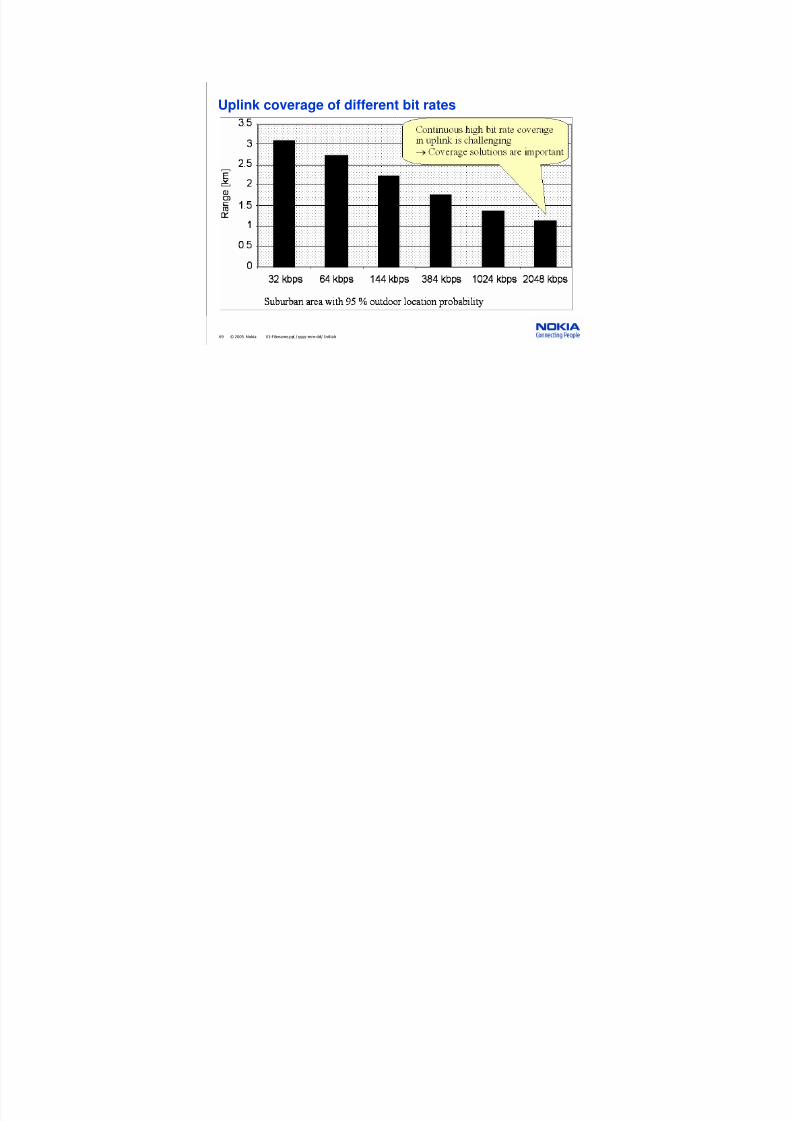
69 © 2005 Nokia V1-Filename.ppt / yyyy-mm-dd/ Initials
Uplink coverage of different bit rates
7/30/2019 03_UMTS Radio Path and Transmission_emad
http://slidepdf.com/reader/full/03umts-radio-path-and-transmissionemad 70/85
70 © 2005 Nokia V1-Filename.ppt / yyyy-mm-dd/ Initials
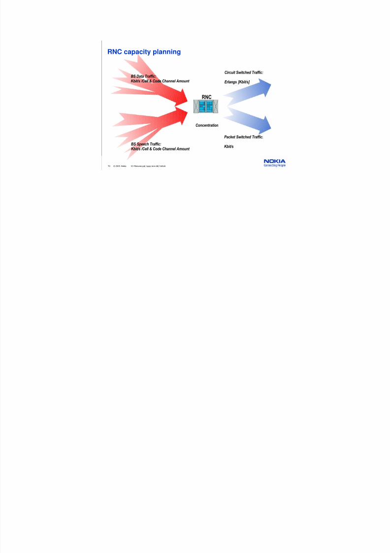
RNC capacity planning
BS Speech Traffic:
Kbit/s /Cell & Code Channel Amount
BS Data Traffic:Kbit/s /Cell & Code Channel Amount
Packet Switched Traffic:
Kbit/s
Circuit Switched Traffic:
Erlangs [Kbit/s]
Concentration
RNC

7/30/2019 03_UMTS Radio Path and Transmission_emad
http://slidepdf.com/reader/full/03umts-radio-path-and-transmissionemad 71/85
71 © 2005 Nokia V1-Filename.ppt / yyyy-mm-dd/ Initials
Smart Radio Concept (SRC)
• Beam steering: optimal baseband combining of 4
uplink signals forms the beam
• can utilise both space and polarisation diversity
• estimated uplink improvement is 6 dB comparedto single antenna operation
WCDMA
ReceiverCombinedreceived
signal

7/30/2019 03_UMTS Radio Path and Transmission_emad
http://slidepdf.com/reader/full/03umts-radio-path-and-transmissionemad 72/85
72 © 2005 Nokia V1-Filename.ppt / yyyy-mm-dd/ Initials
Increase uplink coverage by SRC
Coverage
Capacity
Uplink
Downlink Estimated average gain2.5-3.5 dB compared to2-way diversity
UPLINK relate to Coverage
Parameters :
Uplink:
• Bit rate 144 kbps
• Eb/N0 = 1.5 dB
• Base station noise figure = 4.0 dB
• i=0.65 (3-sector macro)
• Antenna gain 18.0 DBE
• No cable loss = MHA used
• Fast fading margin = 4.0 dB + Soft handover gain = 2.0 dB
• 30% loading -> Interference margin = 1.5 dB
• Max. path loss = 154.4 dB with SRC and 156.9 dB with SRC
Downlink
• Eb/N0 = 5.5 dB
• Mobile station noise figure = 8.0 dB
• i=0.65• Orthogonality = 0.60
• Base station antenna gain 18.0 DBE
• Mobile antenna gain 2.0 DBE
• Cable loss = 4.0 dB
• Max./average path loss = 6 dB
• Soft handover overhead = 40%, Soft handover gain = 2.5 dB

7/30/2019 03_UMTS Radio Path and Transmission_emad
http://slidepdf.com/reader/full/03umts-radio-path-and-transmissionemad 73/85
73 © 2005 Nokia V1-Filename.ppt / yyyy-mm-dd/ Initials
Using downlink diversity
Open loop Closed loop
Feedback used forphasing transmittedsignals→ beam steering
No feedback,time switchedtransmission
Parameters :
Uplink:
• Bit rate 144 kbps
• Eb/N0 = 1.5 dB
• Base station noise figure = 4.0 dB
• i=0.65 (3-sector macro)
• Antenna gain 18.0 DBE
• No cable loss = MHA used
• Fast fading margin = 4.0 dB + Soft handover gain = 2.0 dB
• 30% loading -> Interference margin = 1.5 dB
• Max. path loss = 154.4 dB with SRC and 156.9 dB with SRC
Downlink
• Eb/N0 = 5.5 dB
• Mobile station noise figure = 8.0 dB
• i=0.65• Orthogonality = 0.60
• Base station antenna gain 18.0 DBE
• Mobile antenna gain 2.0 DBE
• Cable loss = 4.0 dB
• Max./average path loss = 6 dB
• Soft handover overhead = 40%, Soft handover gain = 2.5 dB
7/30/2019 03_UMTS Radio Path and Transmission_emad
http://slidepdf.com/reader/full/03umts-radio-path-and-transmissionemad 74/85
74 © 2005 Nokia V1-Filename.ppt / yyyy-mm-dd/ Initials
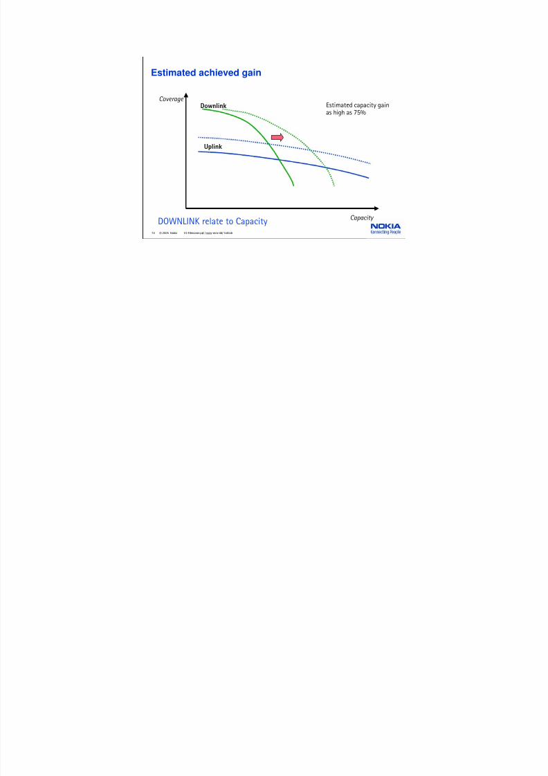
Estimated achieved gain
Coverage
Capacity
Uplink
Downlink Estimated capacity gainas high as 75%
DOWNLINK relate to Capacity

7/30/2019 03_UMTS Radio Path and Transmission_emad
http://slidepdf.com/reader/full/03umts-radio-path-and-transmissionemad 75/85
75 © 2005 Nokia V1-Filename.ppt / yyyy-mm-dd/ Initials
3G-UMTS Radio Path & Transmission Key Points 1
• UMTS FDD & TDD
• WCDMA Carrier 5 MHz (3,84 MHz)
• Direct Sequencing
• Codes: Channelisation Code:
—Spreading
—Separation of user connections
Scrambling Code:
—Separation of users (UL)
—Separation of cells (DL)
• SF= Spreading Factor
• If SF=low => Bit Rate=high + Power=high
• If SF=high => Bit Rate=low + Power=low
• 3 layers of channels: Logical, Transport & Physical

7/30/2019 03_UMTS Radio Path and Transmission_emad
http://slidepdf.com/reader/full/03umts-radio-path-and-transmissionemad 76/85
76 © 2005 Nokia V1-Filename.ppt / yyyy-mm-dd/ Initials
3G-UMTS Radio Path & Transmission Key Points 2
• Receiver in UE and BS: Antimultipath RAKE receiver
• Radio Resource Management in RNC:
• Packet Scheduler => For NRT traffic
• Admission Control => Load target
• Power Control => Open Loop, Closed Loop & Outer Loop
• Load Control => Load target, Interference level
• Resource Management =>Code Allocation
• Handover Control and Macro Diversity
=> Soft, Softer, Hard & Inter System
• Cell Breathing:
• Cell capacity and coverage are related.
7/30/2019 03_UMTS Radio Path and Transmission_emad
http://slidepdf.com/reader/full/03umts-radio-path-and-transmissionemad 77/85
77 © 2005 Nokia V1-Filename.ppt / yyyy-mm-dd/ Initials
3G/UMTS Radio Path &Transmission
Review Questions

7/30/2019 03_UMTS Radio Path and Transmission_emad
http://slidepdf.com/reader/full/03umts-radio-path-and-transmissionemad 78/85
78 © 2005 Nokia V1-Filename.ppt / yyyy-mm-dd/ Initials
1. In UMTS, there are two methods used for transport through the air interface.
The first is UMTS-FDD. What is the second one?
a. TDD, Time Doubled Division
b. CDD, Code Division Duplex
c. TDD, Time Division Duplex
d. CDD, Code Divided Data
2. Which of the following sentences best describes the phenomenon called cellbreathing?
a. When more capacity is used, the cell spreads in size.
b. When more capacity is used, the cell shrinks in size.
c. The cell will adjust its size in line with the furthest users. For example, if the user is
5 km away, the cell is 5 km. If the user is 2 km away, the cell is 2 km.
d. Cell breathing is the height of the cell: from 2 - 3 km towards the atmosphere.
Review (1/8)

7/30/2019 03_UMTS Radio Path and Transmission_emad
http://slidepdf.com/reader/full/03umts-radio-path-and-transmissionemad 79/85
79 © 2005 Nokia V1-Filename.ppt / yyyy-mm-dd/ Initials
3. There are two types of codes used in WCDMA. These are the channelisation
and scrambling codes. Why are the scrambling codes used?
a. To separate downlink physical channels in a cell.
b. To separate user data and signalling in the network.
c. As security to check if the User Equipment (UE) is not stolen.
d. To separate different cells in the downlink direction.
4. In UMTS, there are three layers of channels (logical, transport and physical).Which of the following is not a physical channel?
a. BCCH
b. CCPCH
c. DPCH
d. DPDCH
Review (2/8)
7/30/2019 03_UMTS Radio Path and Transmission_emad
http://slidepdf.com/reader/full/03umts-radio-path-and-transmissionemad 80/85
80 © 2005 Nokia V1-Filename.ppt / yyyy-mm-dd/ Initials
5. Which of the following statements about channelisation is true?
a. The lower the bit rate, the more data can be spread.
b. Before spreading, an error-protection code needs to be added to the
baseband data to ensure a safe path through the air interface.
c. The channelisation code is added as part of the spreading function.
d. The channelisation code depends on the spreading factor used.
e. All of the above.
6. What type of modulation is used in UMTS?
a. GMSK
b. QPSK
c. 8PSK
d. BPSK
Review (3/8)

7/30/2019 03_UMTS Radio Path and Transmission_emad
http://slidepdf.com/reader/full/03umts-radio-path-and-transmissionemad 81/85
81 © 2005 Nokia V1-Filename.ppt / yyyy-mm-dd/ Initials
7. For which of following tasks is the RAKE receiver not responsible?
a. Multipath Propagation Delay
b. Listening to surrounding BTSs
c. Channel coding
d. Speech coding
8. Which of the following is a true statement about Admission Control?
a. The UEs handle resource allocation.
b. The RNC makes the decision of resource allocation, based uponinterference.
c. The RNC will not limit the number of the users on a cell.
d. As more users are allocated a code, the load on a cell remains the same.
Review (4/8)

7/30/2019 03_UMTS Radio Path and Transmission_emad
http://slidepdf.com/reader/full/03umts-radio-path-and-transmissionemad 82/85
82 © 2005 Nokia V1-Filename.ppt / yyyy-mm-dd/ Initials
9. The RNC is responsible for the allocation of codes. Which of the following
sentences (only one) is true?
a. Each cell has a scrambling code that acts like a cell ID.
b. Channelisation codes are dependent upon the subscribers' identity.
c. Scrambling codes are generated randomly.
d. Scrambling codes are used in channelisation.
10. When a mobile is in idle mode, which of the following power controls
is used?
a. Closed loop power control
b. Outer loop power control
c. Internal loop power control
d. Open loop power control
Review (5/8)

7/30/2019 03_UMTS Radio Path and Transmission_emad
http://slidepdf.com/reader/full/03umts-radio-path-and-transmissionemad 83/85
83 © 2005 Nokia V1-Filename.ppt / yyyy-mm-dd/ Initials
Review (6/8)
11. Select the right handover type.
1. Soft 2. Softer 3. Hard
4. Inter-system 5. Not possible
a. Sector 1 to Sector 2 (same BTS)
b. BTS x to BTS y
c. RNC to RNC with Iur interface
d. RNC to RNC with no Iur interface
e. UMTS-FDD to UMTS-TDD
f. WCDMA to GSM
g. WCDMA to IS-95
2
1
1
3
4
4
5

7/30/2019 03_UMTS Radio Path and Transmission_emad
http://slidepdf.com/reader/full/03umts-radio-path-and-transmissionemad 84/85

7/30/2019 03_UMTS Radio Path and Transmission_emad
http://slidepdf.com/reader/full/03umts-radio-path-and-transmissionemad 85/85
85 © 2005 Nokia V1-Filename.ppt / yyyy-mm-dd/ Initials
14. Which of the following sentences is true about WCDMA radio network
planning?
a. Capacity is linked to the number of time slots.
b. Power should be as high as possible to ensure good quality.
c. Coverage and capacity are linked.
d. The size of a cell remains constant.
15. When planning the Iub Interface in UMTS, which of the following
sentences true?
a. Cellular transmission is based upon ATM.
b. GSM and UMTS sites cannot be co-located.
c. Radio links cannot be used to connect BTS together.
d. It is easy to plan the capacity requirements.
Review (8/8)


