Page 1
Datenkommunikation 384.081 - SS 2008
L04 - Network Principles
© 2008, D.I. Manfred Lindner
Page 04 - 1
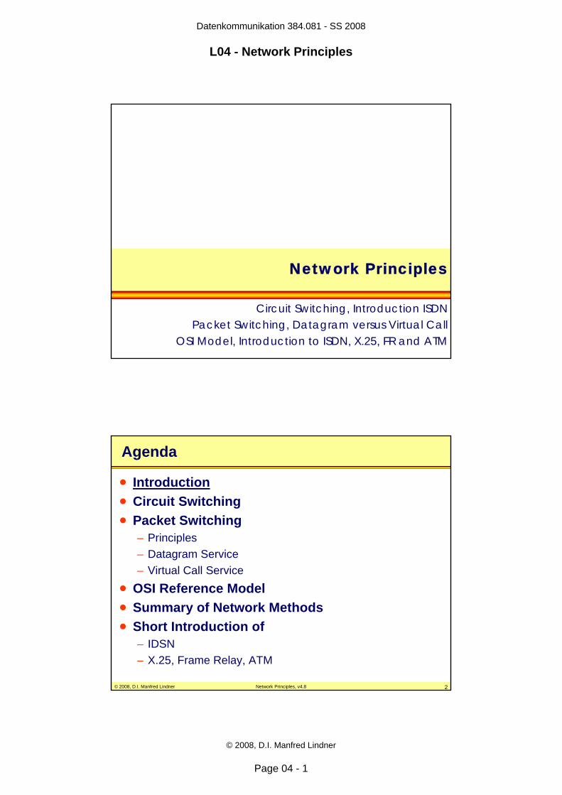
Network Principles
Circuit Switching, Introduction ISDNPacket Switching, Datagram versus Virtual Call
OSI Model, Introduction to ISDN, X.25, FR and ATM
© 2008, D.I. Manfred Lindner Network Principles, v4.8 2
Agenda
• Introduction• Circuit Switching• Packet Switching
– Principles– Datagram Service– Virtual Call Service
• OSI Reference Model• Summary of Network Methods• Short Introduction of
– IDSN– X.25, Frame Relay, ATM
Page 2
Datenkommunikation 384.081 - SS 2008
L04 - Network Principles
© 2008, D.I. Manfred Lindner
Page 04 - 2
© 2008, D.I. Manfred Lindner Network Principles, v4.8 3
Introduction
• chapters about line protocols and TDM techniques have explained – how communication between two devices can be
implemented over a point-to-point physical line using line protocol techniques
– how TDM can be used to provide several communication channels between devices located on two locations
• questions– how should devices to be connected and
how should communication between devices be organized, if there are many devices at different locations?
© 2008, D.I. Manfred Lindner Network Principles, v4.8 4
A
B
C
D
E
F
?
How To Connect All Locations?
Page 3
Datenkommunikation 384.081 - SS 2008
L04 - Network Principles
© 2008, D.I. Manfred Lindner
Page 04 - 3
© 2008, D.I. Manfred Lindner Network Principles, v4.8 5
Any to Any Network Topology
• easy solution– any to any topology (fully meshed)– establish multiple point-to-point lines between devices– use line protocol techniques
© 2008, D.I. Manfred Lindner Network Principles, v4.8 6
A
B
C
D
E
F
Any-to-Any Topology?
Page 4
Datenkommunikation 384.081 - SS 2008
L04 - Network Principles
© 2008, D.I. Manfred Lindner
Page 04 - 4
© 2008, D.I. Manfred Lindner Network Principles, v4.8 7
Networking Techniques
• any-to-any topology is very expensive– many lines are required and hence large number of
transmission equipment (like modems, DSUs, linerepeaters, etc.) necessary
– many physical communication ports are required in devices
– scalability problem: N * (N-1) / 2• to reduce costs
– synchronous or asynchronous time division multiplexing principles can be used in a network environment
– circuit switching based on synchronous TDM – packet switching based on asynchronous (statistical) TDM
© 2008, D.I. Manfred Lindner Network Principles, v4.8 8
Agenda
• Introduction• Circuit Switching• Packet Switching
– Principles– Datagram Service– Virtual Call Service
• OSI Reference Model• Summary of Network Methods• Short Introduction of
– IDSN– X.25, Frame Relay, ATM
Page 5
Datenkommunikation 384.081 - SS 2008
L04 - Network Principles
© 2008, D.I. Manfred Lindner
Page 04 - 5
© 2008, D.I. Manfred Lindner Network Principles, v4.8 9
Circuit Switching
• principle– physical communication ports of devices are connected
locally to synchronous TDM switches – trunk lines T between switches use synchronous time
division multiplexing• e.g. standardized E1 (31 timeslots with 64kbit/s each)
– each physical port is assigned a timeslot on an outgoing trunk for communication with remote device
– switches map timeslots on incoming trunks either to local ports or to timeslots on outgoing trunks (transit switch)
– mapping information• is stored in circuit switching tables
© 2008, D.I. Manfred Lindner Network Principles, v4.8 10
PA1 PA5
PB1
PB5
PC1 PC5
PD1
PD5
PE1
PE5
PF1 PF5
T1
T2
T2
T3T3
T4
T4
T1
A
B
C
D
E
F
1
34
2
P - access line, T - trunk line
Circuit Switching
TDM-Switch
Page 6
Datenkommunikation 384.081 - SS 2008
L04 - Network Principles
© 2008, D.I. Manfred Lindner
Page 04 - 6
© 2008, D.I. Manfred Lindner Network Principles, v4.8 11
PA1 -> T2 (1) : A1-B1PA2 -> T2 (2) : A2-C1PA3 -> T2 (3) : A3-D1PA4 -> T1 (1) : A4- F1PA5 -> T1 (2) : A5-E1
T1 (1) -> PF1T1 (2) -> PE1
T3 (1) -> PD1T2 (1) -> PB1 T2 (2) -> PC1T2 (3) -> T3 (1)
timeslot identifier
PA1 PA5
PB1
PB5
PC1 PC5
PD1
PD5
PE1
PE5
PF1 PF5
A
B
C
D
E
F
1
34
2
circuit switching table switch 1
Connections of Device A
T1
T2
T2
T3T3
T4
T4
T1
P - access line, T - trunk line
© 2008, D.I. Manfred Lindner Network Principles, v4.8 12
PA1 -> T2 (1) : A1-B1PA2 -> T2 (2) : A2-C1PA3 -> T2 (3) : A3-D1PA4 -> T1 (1) : A4- F1PA5 -> T1 (2) : A5-E1
T1 (1) -> PF1T1 (2) -> PE1
T3 (1) -> PD1T2 (1) -> PB1 T2 (2) -> PC1T2 (3) -> T3 (1)
timeslot identifier
PA1 PA5
PB1
PB5
PC1 PC5
PD1
PD5
PE1
PE5
PF1 PF5
A
B
C
D
E
F
1
34
2
circuit switching table switch 1
Connections of Device ACircuit Path PA3 (A) - PD1 (D)
T1
T2
T2
T3T3
T4
T4
T1
P - access line, T - trunk line
Page 7
Datenkommunikation 384.081 - SS 2008
L04 - Network Principles
© 2008, D.I. Manfred Lindner
Page 04 - 7
© 2008, D.I. Manfred Lindner Network Principles, v4.8 13
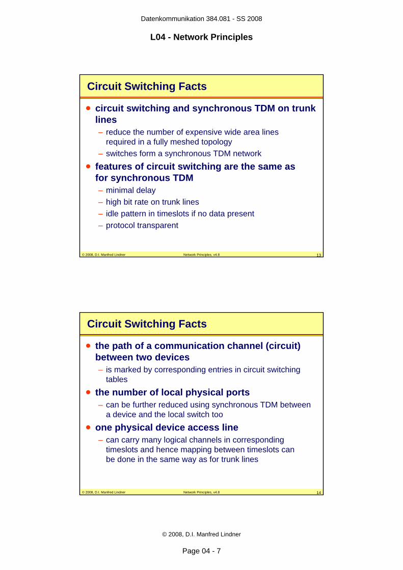
Circuit Switching Facts
• circuit switching and synchronous TDM on trunk lines – reduce the number of expensive wide area lines
required in a fully meshed topology– switches form a synchronous TDM network
• features of circuit switching are the same asfor synchronous TDM– minimal delay– high bit rate on trunk lines– idle pattern in timeslots if no data present– protocol transparent
© 2008, D.I. Manfred Lindner Network Principles, v4.8 14
Circuit Switching Facts
• the path of a communication channel (circuit) between two devices– is marked by corresponding entries in circuit switching
tables• the number of local physical ports
– can be further reduced using synchronous TDM betweena device and the local switch too
• one physical device access line – can carry many logical channels in corresponding
timeslots and hence mapping between timeslots can be done in the same way as for trunk lines
Page 8
Datenkommunikation 384.081 - SS 2008
L04 - Network Principles
© 2008, D.I. Manfred Lindner
Page 04 - 8
© 2008, D.I. Manfred Lindner Network Principles, v4.8 15
TA (1) -> T2 (1) : A1-B1TA (2) -> T2 (2) : A2-C1TA (3) -> T2 (3) : A3-D1TA (4) -> T1 (1) : A4-F1TA (5) -> T1 (2) : A5-E1
T1 (1) -> TF (1)T1 (2) -> TE (1)
T3 (1) -> TD (1)T2 (1) -> TB (1) T2 (2) -> TC (1)T2 (3) -> T3 (1)
timeslot identifier
TA
TB
TC
TD
TE
TF
A
B
C
D
E
F
1
34
2
TA, TB, ... TF use TDM technique
TDM lines to Devices
switching table switch 1
T1
T2
T2
T3T3
T4
T4
T1
© 2008, D.I. Manfred Lindner Network Principles, v4.8 16
Services based on Circuit Switching
• circuit switching table– could be static
• entries are configured by TDM network administrator • permanent circuit service
– or dynamic (fail-safe)• entries are changed automatically by TDM network management
protocol to switch over to a redundant path in case a trunk linebreaks
• soft permanent circuit service
– or dynamic (on demand)• end-systems use signaling protocol to local TDM switch in order to
transport setup or tear down requests• TDM switches establish path (corresponding entries in circuit
switching tables) using their own signaling protocols• switched circuit service
Page 9
Datenkommunikation 384.081 - SS 2008
L04 - Network Principles
© 2008, D.I. Manfred Lindner
Page 04 - 9
© 2008, D.I. Manfred Lindner Network Principles, v4.8 17
Circuit Switching Data Networks
• network providers offer permanent circuit services– based on redundant, synchronous TDM networks (PDH or SDH)
• with permanent entries in circuit switching tables• automatic switchover in case of trunk failure• digital leased line
• network provider offer switched circuit services– based on ISDN
• with dynamic entries in circuit switching tables generated on demand• outband signaling (D-channel) between endsystem and local TDM switch• ISDN-LE (Local Exchange) instead of TDM switch• communication between ISDN-LEs based on Signaling System 7 (SS7)
• base for both services– underlying (PDH), SDH infrastructure for transporting channels over
wide areas
© 2008, D.I. Manfred Lindner Network Principles, v4.8 18
ISDN
• Integrated Services Digital Network (ISDN)– offers transport of voice, video and data– all-digital interface at subscriber outlet
• standardized user-to-network interface (UNI)– BRI (Basic Rate Interface)– PRI (Primary Rate Interface)
Page 10
Datenkommunikation 384.081 - SS 2008
L04 - Network Principles
© 2008, D.I. Manfred Lindner
Page 04 - 10
© 2008, D.I. Manfred Lindner Network Principles, v4.8 19
ISDN User-to-Network Interface (UNI)
ISDN-TE
ISDNNetwork Service
physical access link
ISDN-LE
channelfor user data(B-channel)
channelfor signaling(D-channel)
…
logical channels multiplexed on physical channel
© 2008, D.I. Manfred Lindner Network Principles, v4.8 20
Basic Rate Interface (BRI)
– 2 B (bearer) channels with 64 kbit/s each• carrying digitized voice or data
– 1 D (data) channel with 16 kbit/s• for signaling purposes (e.g. Q.931 protocol)
– 2 B and D are synchronous TDM-multiplexed on physical access line
BRI
2 × B
D
TelcoNetwork
144 kbit/s (plus overhead)
ISDNend system ISDN LE
UNI (BRI)
Page 11
Datenkommunikation 384.081 - SS 2008
L04 - Network Principles
© 2008, D.I. Manfred Lindner
Page 04 - 11
© 2008, D.I. Manfred Lindner Network Principles, v4.8 21
Primary Rate Interface (PRI)
– 30 B (Bearer) channels with 64 kbit/s each– 1 D (Data) channel with 64 kbit/s
• for signalling purposes (e.g. Q.931 protocol)
– 30 B and D are synchronous TDM-multiplexed on one physical access line
30 × B
D
PRI 2.048 Mbit/s (E1 Frames)
ISDNend system ISDN LE
UNI (BRI)
© 2008, D.I. Manfred Lindner Network Principles, v4.8 22
Call Setup on D channel
Data or Voice Transfer on B channel
Call Release on D channel
Procedures
Page 12
Datenkommunikation 384.081 - SS 2008
L04 - Network Principles
© 2008, D.I. Manfred Lindner
Page 04 - 12
© 2008, D.I. Manfred Lindner Network Principles, v4.8 23
Agenda
• Introduction• Circuit Switching• Packet Switching
– Principles– Datagram Service– Virtual Call Service
• OSI Reference Model • Summary of Network Methods• Short Introduction of
– IDSN– X.25, Frame Relay, ATM
© 2008, D.I. Manfred Lindner Network Principles, v4.8 24
Packet Switching Principles 1
• implementation of asynchronous, statistical TDMin a network environment
• network topology consists of– packet switches– trunk lines to connect packet switches– access lines to connect devices
• devices connected to packet switches– end systems
• packet switches– intermediate systems
Page 13
Datenkommunikation 384.081 - SS 2008
L04 - Network Principles
© 2008, D.I. Manfred Lindner
Page 04 - 13
© 2008, D.I. Manfred Lindner Network Principles, v4.8 25
Packet Switching Principles 2
• statistical TDM on trunks and access lines– allows many end systems to communicate without
reserving capacity on a trunk or access line– needs therefore explicit addressing information
• source address• destination address
• statistical TDM on trunks and access lines– avoids large number of physical point-to-point lines
required in a pure any-to-any topology– limits the bit rate necessary on trunk lines
• bit rate will be calculated to carry the average trafficbetween end systems
© 2008, D.I. Manfred Lindner Network Principles, v4.8 26
PED3
A
D C
B1
2 3 4
56
PA
T1
T1
T1T2
T4
T2
PD
T3
T1T2
PC
T3
T4T2
T1
T2
PB
Packet Switching Topology
Unique Network Address of end system
Page 14
Datenkommunikation 384.081 - SS 2008
L04 - Network Principles
© 2008, D.I. Manfred Lindner
Page 04 - 14
© 2008, D.I. Manfred Lindner Network Principles, v4.8 27
Packet Switching Principles 3
• statistical TDM on access line– requires a protocol between end systems and packet
switches• addressing• optional flow control
– is not protocol-transparent– hence end system must speak language of the packet
switch• redundant trunk lines
– can provide redundant paths in case of failure – can be used for load sharing
© 2008, D.I. Manfred Lindner Network Principles, v4.8 28
Packet Switching Principles 4
• end systems – break information in small pieces called packets– deliver these packets to local packet switch
• packets contain addressing information • packet switches
– buffer incoming packets– use address information to decide where to forward them– put packets in outgoing queues after decision– transmit packets waiting in queues
• store and forward technology
Page 15
Datenkommunikation 384.081 - SS 2008
L04 - Network Principles
© 2008, D.I. Manfred Lindner
Page 04 - 15
© 2008, D.I. Manfred Lindner Network Principles, v4.8 29
A
D C
B1
2 3 4
56
Packet Forwarding Principle (Store and Forward)
A B
... Packet payload
A B A B
A Btime t0
time t2 time t4
time t6
time t1forwarding decision
of PS2time t3
forwarding decisionof PS3
time t5forwarding decision
of PS4
A B ... Source Address / Destination Address
© 2008, D.I. Manfred Lindner Network Principles, v4.8 30
Principle of Packet Switching 5
• forwarding of packets is based on tables– switching tables
• used for connection-oriented services• virtual call service
– routing tables• used for connection-less services• datagram service
• in these tables– information how to reach certain destinations is stored
• mapping between destination address or connection identifier andoutgoing trunk or access port
– “signposts”
Page 16
Datenkommunikation 384.081 - SS 2008
L04 - Network Principles
© 2008, D.I. Manfred Lindner
Page 04 - 16
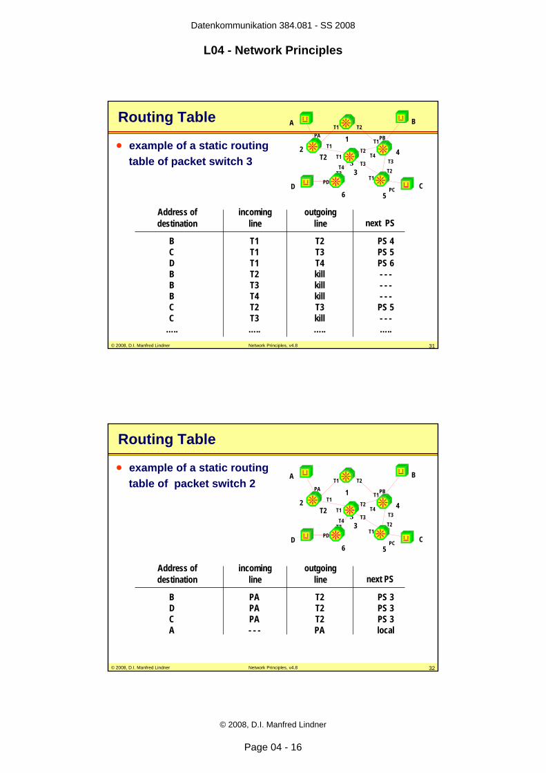
© 2008, D.I. Manfred Lindner Network Principles, v4.8 31
Address ofdestination
incomingline
outgoingline next PS
BCDBBBCC
…..
T1T1T1T2T3T4T2T3…..
T2T3T4killkillkillT3kill…..
PS 4PS 5PS 6- - -- - -- - -
PS 5- - -…..
Routing Table
• example of a static routing table of packet switch 3 PED
3
A
D C
B
12
3
4
56
PAT1
T1
T1T2T4
T2PD
T3
T1T2
PC
T3T4
T2T1
T2
PB
© 2008, D.I. Manfred Lindner Network Principles, v4.8 32
Address ofdestination
incomingline
outgoingline next PS
BDCA
PAPAPA- - -
T2T2T2PA
PS 3PS 3PS 3local
Routing Table
• example of a static routing table of packet switch 2
PED3
A
D C
B
12
3
4
56
PAT1
T1
T1T2T4
T2PD
T3
T1T2
PC
T3T4
T2T1
T2
PB
Page 17
Datenkommunikation 384.081 - SS 2008
L04 - Network Principles
© 2008, D.I. Manfred Lindner
Page 04 - 17
© 2008, D.I. Manfred Lindner Network Principles, v4.8 33
Routing - Addressing
• routing in packet switched networks– process of path selection in order to forward a packet to a
given destination– selection based on addresses
• addresses specify the location of end system– contain topology information– addresses must be unique within the network to enable
routing• a protocol using unique and structured
addresses– is called routed or routable protocol
© 2008, D.I. Manfred Lindner Network Principles, v4.8 34
Static Routing
• static routing– based on preconfigured routing tables
• done by network administrator
– routing table entries are static
• the basic problem of routing– consistency of routing tables (distributed database)– static routing: task of network administrator– dynamic routing: task of routing protocol
Page 18
Datenkommunikation 384.081 - SS 2008
L04 - Network Principles
© 2008, D.I. Manfred Lindner
Page 04 - 18
© 2008, D.I. Manfred Lindner Network Principles, v4.8 35
Dynamic Routing
• dynamic routing– based on distributed routing processes– communication between processes (packet switches)
• is done via routing protocol
– routing protocol is used• to find out the network topology• to calculate all possible paths to a given location and select one
path (best path) in case of redundancy
– best paths are stored in the routing table– routing table entries are variable (dynamic)
• caused by network topology changes
© 2008, D.I. Manfred Lindner Network Principles, v4.8 36
Routing Table Usage / Type of Service
• routing tables are differently used – depending on the type of service of the packet switching
network
• packet switched network based on– connection-oriented service (CO)
• routing tables are used to generate entries in switching tables• only needed for connection establishment• after connection establishment, switching tables are used
to control the forwarding of data packets
– connection-less service (CL)• routing tables are used to control the forwarding of each packet
Page 19
Datenkommunikation 384.081 - SS 2008
L04 - Network Principles
© 2008, D.I. Manfred Lindner
Page 04 - 19
© 2008, D.I. Manfred Lindner Network Principles, v4.8 37
Agenda
• Introduction• Circuit Switching• Packet Switching
– Principles– Datagram Service– Virtual Call Service
• OSI Reference Model • Summary of Network Methods• Short Introduction of
– IDSN– X.25, Frame Relay, ATM
© 2008, D.I. Manfred Lindner Network Principles, v4.8 38
Datagram Service Principles
• connection-less service– packets can be sent without establishing a logical
connection between end systems in advance– packets have no sequence numbers, are called
datagrams• every incoming packet
– is processed independently by packet switches• the forwarding decision for incoming packets
– depends on the current state of the routing table• each packet contains
– complete address information (source and destination)
Page 20
Datenkommunikation 384.081 - SS 2008
L04 - Network Principles
© 2008, D.I. Manfred Lindner
Page 04 - 20
© 2008, D.I. Manfred Lindner Network Principles, v4.8 39
A
D C
B1
2 3 4
56
Routing Tables
B PS3C PS3D PS3
to next hopB localC PS5D PS3
to next hop
B PS4C PS5D PS6
to next hop
sourceaddress
A B
destinationaddress
... payload
Routing Tableof PS 4A B A B
A B
© 2008, D.I. Manfred Lindner Network Principles, v4.8 40
A C A B
A C A B
D B A B
D B A B
D B
D B
A C
A C
A
D C
B1
2 3 4
56
Datagram Forwarding
Page 21
Datenkommunikation 384.081 - SS 2008
L04 - Network Principles
© 2008, D.I. Manfred Lindner
Page 04 - 21
© 2008, D.I. Manfred Lindner Network Principles, v4.8 41
Datagram Service Facts 1
• rerouting in case of topology changes or load balancing means– packets with the same address information can take
different paths to destination – packets may arrive out of sequence
• packets may be discarded by packet switches – in case of network congestion– in case of transmission errors
• the end systems are responsible– for error recovery (retransmission of dropped or
corrupted packets)– for sequencing and handling of duplicates
© 2008, D.I. Manfred Lindner Network Principles, v4.8 42
Datagram Service Facts 2
• connectionless behavior– no reservation of resources is possible in advance
• bandwidth on trunk line• buffer memory of packet switches
• best effort service– transport of packets depends on available resources
• inconsistent routing tables– could cause endless circulation of packets
• endless circulation means blocking of buffer memory• special methods used for avoidance• maximum time to live, maximum hop count, etc.
Page 22
Datenkommunikation 384.081 - SS 2008
L04 - Network Principles
© 2008, D.I. Manfred Lindner
Page 04 - 22
© 2008, D.I. Manfred Lindner Network Principles, v4.8 43
Datagram Service
• advantages– small protocol overhead (easy to implement in end
systems and packet switches) – fastest delivery of data between end systems because no
connection must be established in advance • disadvantage
– delivery of packets is not guaranteed by the network, must be handled by end systems using higher layer protocol
– proactive flow control is not possible
© 2008, D.I. Manfred Lindner Network Principles, v4.8 44
Network Technologies basedon Datagram Method• IP
– packet is called datagram– end system is called IP host– packet switch is called router
• IPX (Novell)• XNS• Appletalk• Decnet Phase IV• OSI CNLP
Page 23
Datenkommunikation 384.081 - SS 2008
L04 - Network Principles
© 2008, D.I. Manfred Lindner
Page 04 - 23
© 2008, D.I. Manfred Lindner Network Principles, v4.8 45
Agenda
• Introduction• Circuit Switching• Packet Switching
– Principles– Datagram Service– Virtual Call Service
• OSI Reference Model • Summary of Network Methods• Short Introduction of
– IDSN– X.25, Frame Relay, ATM
© 2008, D.I. Manfred Lindner Network Principles, v4.8 46
Agenda
• Introduction• Circuit Switching
– Principles– ISDN
• Packet Switching– Principles– Datagram Service– Virtual Call Service– X.25, Frame Relay, ATM
• Summary of Network Methods• OSI Reference Model
Page 24
Datenkommunikation 384.081 - SS 2008
L04 - Network Principles
© 2008, D.I. Manfred Lindner
Page 04 - 24
© 2008, D.I. Manfred Lindner Network Principles, v4.8 47
Virtual Call Principles
• connection oriented service– special control packets (call setup packets) establish a
virtual point-to-point connection (virtual circuit) between end systems first
– after connection is established, data packets can be transmitted across that virtual circuit
– typically connection will be closed after data transfer is finished
• different methods are possible– to establish a virtual call service
© 2008, D.I. Manfred Lindner Network Principles, v4.8 48
Virtual Call Principles
• one possible way– call setup packets are transported across the network like
datagrams– for path decisions routing tables are used– call setup packets contain
• unique address information of source and destination endsystems• connection identifier to represent the requested connection
– during proceeding of call setup packet • the connection identifier on an incoming line will be mapped to a
connection identifier on the outgoing line
– connection identifier has only local significance• meaning agreed between two directly connected devices
– e.g. endsystem and local packet switch or packet switch to next packet switch and so on
Page 25
Datenkommunikation 384.081 - SS 2008
L04 - Network Principles
© 2008, D.I. Manfred Lindner
Page 04 - 25
© 2008, D.I. Manfred Lindner Network Principles, v4.8 49
Virtual Call Principles
• one possible way (cont.)– during call setup the information about
• incoming connection identifier / Incoming port to outgoing connection identifier / outgoing port is stored in the switching table
– path of call setup packet • is marked by corresponding switching table entries
– if connection establishment is successful• each data or control packet using that connection will be
transmitted along that established path
– virtual point-to-point connection will be represented• by the local identifiers used between end systems and switches• by the sequence of local identifiers used on trunk lines
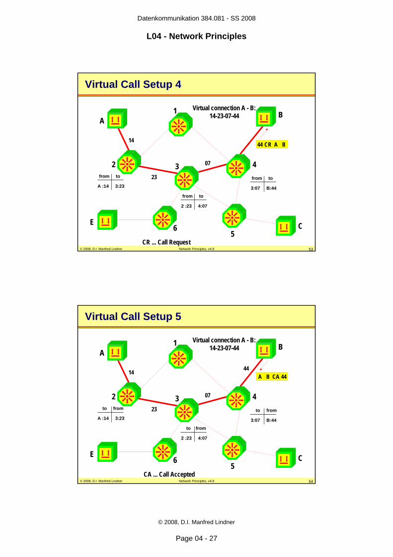
© 2008, D.I. Manfred Lindner Network Principles, v4.8 50
14 CR A B
A
E C
B1
2 3 4
56
CR ... Call Request
Virtual Call Setup 1
A :14
from to
from to
from toB PS3C PS3E PS3
to next hop
Switching Tableof PS 4
uniqueaddresses
localconnection
identifierpacket
type
Page 26
Datenkommunikation 384.081 - SS 2008
L04 - Network Principles
© 2008, D.I. Manfred Lindner
Page 04 - 26
© 2008, D.I. Manfred Lindner Network Principles, v4.8 51
23 CR A B
A
E C
B1
2 3 4
56
CR ... Call Request
14
Virtual Call Setup 2
A :14 3:23
from to
2 :23
from to from to
B PS4C PS5E PS6
to next hop
© 2008, D.I. Manfred Lindner Network Principles, v4.8 52
A
E C
B1
2 3 4
56
CR ... Call Request
14
07 CR A B
23
Virtual Call Setup 3
3:07
from to
A :14 3:23
from to
2 :23 4:07
from to
B localC PS5E PS3
to next hop
Page 27
Datenkommunikation 384.081 - SS 2008
L04 - Network Principles
© 2008, D.I. Manfred Lindner
Page 04 - 27
© 2008, D.I. Manfred Lindner Network Principles, v4.8 53
44 CR A B
A
E C
B1
2 3 4
56
CR ... Call Request
14
23
07
Virtual connection A - B:14-23-07-44
Virtual Call Setup 4
A :14 3:23
from to
3:07 B:44
from to
2 :23 4:07
from to
© 2008, D.I. Manfred Lindner Network Principles, v4.8 54CA ... Call Accepted
A B CA 44
A
E C
B1
2 3 4
56
14
23
07
Virtual connection A - B:14-23-07-44
44
Virtual Call Setup 5
A :14 3:23
to from
3:07 B:44
to from
2 :23 4:07
to from
Page 28
Datenkommunikation 384.081 - SS 2008
L04 - Network Principles
© 2008, D.I. Manfred Lindner
Page 04 - 28
© 2008, D.I. Manfred Lindner Network Principles, v4.8 55CA ... Call Accepted
A
E C
B1
2 3 4
56
14
23
07
Virtual connection A - B:14-23-07-44
44A B CA 14
Virtual Call Setup 6
A :14 3:23
to from
3:07 B:44
to from
2 :23 4:07
to from
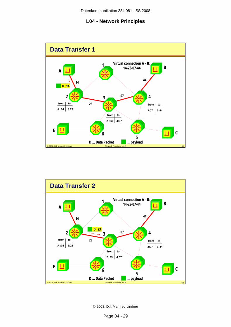
© 2008, D.I. Manfred Lindner Network Principles, v4.8 56
Forwarding Data
• all data packets and control packets use local identifiers as address information only– to indicate to which connection they belong – to which destination they should be delivered
• unique source and destination addresses – are not required during data transfer phase
• mapping of incoming identifiers to outgoing identifiers– is done by packet switches hop by hop by consulting the
switching table only• forwarding decision based on switching table
– routing table not necessary in that phase
Page 29
Datenkommunikation 384.081 - SS 2008
L04 - Network Principles
© 2008, D.I. Manfred Lindner
Page 04 - 29
© 2008, D.I. Manfred Lindner Network Principles, v4.8 57
A
E C
B1
2 3 4
56
14
23
07
Virtual connection A - B:14-23-07-44
44D 14
D ... Data Packet … payload
Data Transfer 1
A :14 3:23
from to
3:07 B:44
from to
2 :23 4:07
from to
© 2008, D.I. Manfred Lindner Network Principles, v4.8 58
A
E C
B1
2 3 4
56
14
23
07
Virtual connection A - B:14-23-07-44
44
D 23
D ... Data Packet … payload
Data Transfer 2
A :14 3:23
from to
3:07 B:44
from to
2 :23 4:07
from to
Page 30
Datenkommunikation 384.081 - SS 2008
L04 - Network Principles
© 2008, D.I. Manfred Lindner
Page 04 - 30
© 2008, D.I. Manfred Lindner Network Principles, v4.8 59
A
E C
B1
2 3 4
56
14
23
07
Virtual connection A - B:14-23-07-44
44
D 07
D ... Data Packet … payload
Data Transfer 3
A :14 3:23
from to
3:07 B:44
from to
2 :23 4:07
from to
© 2008, D.I. Manfred Lindner Network Principles, v4.8 60
A
E C
B1
2 3 4
56
14
23
07
Virtual connection A - B:14-23-07-44
44D 44
D ... Data Packet … payload
Data Transfer 4
A :14 3:23
from to
3:07 B:44
from to
2 :23 4:07
from to
Page 31
Datenkommunikation 384.081 - SS 2008
L04 - Network Principles
© 2008, D.I. Manfred Lindner
Page 04 - 31
© 2008, D.I. Manfred Lindner Network Principles, v4.8 61
Virtual Call Service Facts
• the sequence of data packets is guaranteed by the network– packets can use the established path only
• path selection is done during connection setup– afterwards, entries of routing table are not used
• in case of trunk line or packet switch failure– virtual circuits will be closed and must be reestablished
again by end systems using call setup packets– if there is at least one redundant path, packet switches
can establish a new virtual circuit taking the redundant path
© 2008, D.I. Manfred Lindner Network Principles, v4.8 62
Multiplexing - Logical Channels
• connection identifier are the base – for maintaining several virtual circuits or logical channels
on one physical link• therefore multiplexing
– several logical channels on the link between end system and local packet switch are possible
• connection identifiers– have in principle the same meaning as port identifiers
used for asynchronous TDM on a point-to-point line– some examples
• X.25 -> LCN (logical channel number)• Frame Relay -> DLCI (data link connection identifier)• ATM -> VPI/VCI (virtual path/channel identifier)
Page 32
Datenkommunikation 384.081 - SS 2008
L04 - Network Principles
© 2008, D.I. Manfred Lindner
Page 04 - 32
© 2008, D.I. Manfred Lindner Network Principles, v4.8 63
A
E C
B14
14
07
virtual circuit A-B (14-23-07-44)
44
27
23
07
44
virtual circuit A-C (27-14-07-44)
Example Virtual Circuits
© 2008, D.I. Manfred Lindner Network Principles, v4.8 64
Services based on Virtual Call Method
• SVC service– Switched Virtual Circuit– virtual circuits require establishing and clearing
• PVC service– Permanent Virtual Circuit– virtual circuits do not require establishing and clearing
done by call setup and call release– circuits are permanently available for data transfer
Page 33
Datenkommunikation 384.081 - SS 2008
L04 - Network Principles
© 2008, D.I. Manfred Lindner
Page 04 - 33
© 2008, D.I. Manfred Lindner Network Principles, v4.8 65
Flow Control, QoS
• connection-oriented packet switching– allows flow control procedures between end system and
packet switch because of connection-oriented approach• in connectionless packet switching networks flow control is not or
only poorly implemented
– flow control procedures can avoid buffer overflow and hence network congestion
– allows reservation of resources• capacity, buffers, cpu time, etc.
– can offer Quality of Service (QoS)– call setup can be denied by network if QoS can not be
guaranteed
© 2008, D.I. Manfred Lindner Network Principles, v4.8 66
Virtual Call Service
• advantages– required resources of packet switches can be reserved
during call setup and hence QoS could be provided– end system view of the network
• reliable point-to-point transport pipe based on network internal error recovery, flow control and sequencing procedures (X.25)
• higher protocol layers can rely on network services (X.25)
– readiness for receipt is tested in advance• call setup of SVC service
• disadvantages– call setup takes time – more complex protocols for end systems and packet
switches than datagram service
Page 34
Datenkommunikation 384.081 - SS 2008
L04 - Network Principles
© 2008, D.I. Manfred Lindner
Page 04 - 34
© 2008, D.I. Manfred Lindner Network Principles, v4.8 67
Network Technologies basedon Virtual Call Method• X.25
– reliable transport pipe because of protocol inherent error recovery and flow control
– local identifier = LCN; in-band signaling• Frame Relay
– virtual circuit technique but no error recovery– congestion indication instead of flow control– local identifier = DLCI; out-band signaling
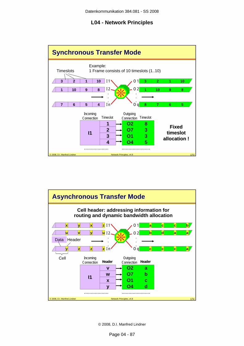
• ATM– same as Frame Relay but packets with fixed length – hence called cell switching– local identifier = VPI/VCI; out-band signaling
© 2008, D.I. Manfred Lindner Network Principles, v4.8 68
Agenda
• Introduction• Circuit Switching• Packet Switching
– Principles– Datagram Service– Virtual Call Service
• OSI Reference Model • Summary of Network Methods• Short Introduction of
– IDSN– X.25, Frame Relay, ATM
Page 35
Datenkommunikation 384.081 - SS 2008
L04 - Network Principles
© 2008, D.I. Manfred Lindner
Page 04 - 35
© 2008, D.I. Manfred Lindner Network Principles, v4.8 69
Standards
• We need networking standards– Ensure interoperability – Large market, lower cost
(mass production)• Vendors need standards
– Good for marketing• Vendors create standards
– Bad for competitors, hard to catch up• But:
– Slow standardization processes freeze technology...
© 2008, D.I. Manfred Lindner Network Principles, v4.8 70
Who Defines Standards?
– ISO – Anything• International Standards Organization (ISO)• International agency for the development of standards in many
areas, founded 1946, currently 89 member countries
– IETF – Internet – ITU-T (former CCITT) – Telco Technologies– CEPT - PTT Technologies– ETSI - European Standards– ANSI - North American Standards– ATM-Forum, Frame Relay Forum, MPLS Forum– IEEE – LAN Protocols– DIN, ÖNORM, …. National Standards
Page 36
Datenkommunikation 384.081 - SS 2008
L04 - Network Principles
© 2008, D.I. Manfred Lindner
Page 04 - 36
© 2008, D.I. Manfred Lindner Network Principles, v4.8 71
Standards Types
• De facto standards– anyone can create them– e.g. Internet RFCs
• De jure standards– created by a standardization organization– e.g. ISO/OSI, ITU-T
© 2008, D.I. Manfred Lindner Network Principles, v4.8 72
Idea of Layering and Services
• because communication between systems can be a very complex task– divide task of communication in multiple sub-tasks
• so called layers– hence every layer implements only a part of the overall
communication systems• hierarchically organized
– each layer receives services from the layer below– each layer serves for the layer above
• good for interoperability– capsulated entities and interfaces
• but increases complexity
Page 37
Datenkommunikation 384.081 - SS 2008
L04 - Network Principles
© 2008, D.I. Manfred Lindner
Page 04 - 37
© 2008, D.I. Manfred Lindner Network Principles, v4.8 73
ISO/OSI Reference Model
• where to define layers?– group functions (services) together– when changes in technology occur
• why to define layers– to allow changes in protocol and HW– to utilize existing protocols and HW
• layering of the ISO/OSI Reference Model– Open Systems Interconnection – defines tasks and interactions of seven layers– framework for development of communication standards– system-internal implementation is out of the scope – only external behavior of a system is defined by standards
© 2008, D.I. Manfred Lindner Network Principles, v4.8 74
Basic Idea of the OSI Model
• each layer depends on services of the layer below in order to provide its own services to the upper layer– service specification standards
• representation of a layer within a system– is called entity (e.g. a particular task or subroutine)
• in order to fulfill the task of a layer – entities use their own system internal resources as well as
peer-to-peer communication based on layer specific protocol
– protocol specification standards
Page 38
Datenkommunikation 384.081 - SS 2008
L04 - Network Principles
© 2008, D.I. Manfred Lindner
Page 04 - 38
© 2008, D.I. Manfred Lindner Network Principles, v4.8 75
Application Layer
Presentation Layer
Session Layer
Transport Layer
Network Layer
Link Layer
Physical Layer
Physical Line
real transportpeer to peer communication on a logical connectionusing the layer-specific protocol
OSI 7 Layer Model
Application Layer
Presentation Layer
Session Layer
Transport Layer
Network Layer
Link Layer
Physical Layer
© 2008, D.I. Manfred Lindner Network Principles, v4.8 76
Application XApplication Presentation
SessionTransportNetworkData LinkPhysical
Physical Transmission Media
Application XApplication Presentation
SessionTransportNetworkData LinkPhysicalEncoded Bitstream
N-PDULH LTT-PDUNH
THSH
PHAH
S-PDUP-PDU
A-PDUDataData
Encapsulation Decapsulation
Frame Encapsulation and Decapsulation
Page 39
Datenkommunikation 384.081 - SS 2008
L04 - Network Principles
© 2008, D.I. Manfred Lindner
Page 04 - 39
© 2008, D.I. Manfred Lindner Network Principles, v4.8 77
OSI Speak (1)
– Entities• anything capable of sending or receiving information
– System• physically distinct object which contains one or more entities
– Protocol• set of rules governing the exchange of data between two entities
– Layer• a set of entities
– Interface• boundary between two layers
– Service Access Point (SAP)• virtual port where services are passed through
– Service Primitive• way to request a service from a lower layer or indicate the
presence of an event to the upper layer
© 2008, D.I. Manfred Lindner Network Principles, v4.8 78
OSI Speak (2)
(N) Layer
(N+1) Layer
(N-1) Layer
Interface
Interface
(N) Layer Entity
(N+1) Layer Entity
(N+1) Layer Entity
(N-1) Layer Entity
(N-1) Layer Entity
"Protocol"
Service AccessPoint (SAP)
Service Primitives
Service Primitives
(N) Layer Entity
Page 40
Datenkommunikation 384.081 - SS 2008
L04 - Network Principles
© 2008, D.I. Manfred Lindner
Page 04 - 40
© 2008, D.I. Manfred Lindner Network Principles, v4.8 79
OSI Speak (3)
– Interface Data Unit (IDU)• data unit for vertical communication (between adjacent layers of
same system)
– Protocol Data Unit (PDU)• data unit for horizontal communication (between same layers of
peering systems)
– Interface Control Information (ICI)• part of IDU,• destined for entity in target-layer
– Service Data Unit (SDU)• Part of IDU,• destined for further communication• contains actual data
© 2008, D.I. Manfred Lindner Network Principles, v4.8 80
OSI Speak (4)
(N) Layer
(N+1) Layer
Interface
(N) Layer Entity
(N+1) Layer Entity
(N) Layer Entity
ICI SDUIDU
ICI SDU
SDU NHN-PDU
SAPVertical
Communication
HorizontalCommunication
Page 41
Datenkommunikation 384.081 - SS 2008
L04 - Network Principles
© 2008, D.I. Manfred Lindner
Page 04 - 41
© 2008, D.I. Manfred Lindner Network Principles, v4.8 81
OSI Model Intermediate Systems
• in end systems (ES)– all seven layers must be implemented for communication
between network applications of different computers • if two end systems are not directly connected via
one physical link– relay systems / intermediate systems are necessary
• intermediate systems (IS) – store and forward devices– packet switches– require routing / switching functionality– only lower layers (1-3) are necessary
© 2008, D.I. Manfred Lindner Network Principles, v4.8 82
Application Layer Protocol
Presentation Layer Protocol
Session Layer Protocol
Transport Layer Protocol
765432
32
32
32
32
765432
1 1 1 1 1 1
LAN A Intermediate Network LAN B
ES A ES BIS 1 IS 2
OSI Model with Intermediate Systems
Page 42
Datenkommunikation 384.081 - SS 2008
L04 - Network Principles
© 2008, D.I. Manfred Lindner
Page 04 - 42
© 2008, D.I. Manfred Lindner Network Principles, v4.8 83
ES A ES B
LAN 1POTS … Plain Old Telephony System
WAN´s
7654321
Appl.7654321
Appl.X.25ISDN
IS 23
2 21 1
IS 13
2 21 1
LAN 2
M M
IS 33
2 21 1
Example Topology with ES and IS
POTS
LAN 3
© 2008, D.I. Manfred Lindner Network Principles, v4.8 84
Tasks of the Physical Layer 1
• access to physical medium• transmission of bit streams• electrical and mechanical interface
specifications• signal encoding, clock synchronization• activation and deactivation of links between end
systems (link management)
Page 43
Datenkommunikation 384.081 - SS 2008
L04 - Network Principles
© 2008, D.I. Manfred Lindner
Page 04 - 43
© 2008, D.I. Manfred Lindner Network Principles, v4.8 85
7654321
Appl.7654321
Appl.
X.25ISDN
32 21 1
32 21 1 M M
32 21 1
Physical Layer 1
POTS
Layer 1 Protocol Layer 1 Protocol
© 2008, D.I. Manfred Lindner Network Principles, v4.8 86
Physical Layer Standards
• LANs– 802.3 (Ethernet: 10Base5, 10Base2, 10BaseT, etc.)– Ethernet V2 (Physical Layer Part)– 802.5 (Token Ring: Physical Layer Part)
• WANs– V.24/V.28, RS 232C, V.10, V11– V.35, V.36, RS 449– X.21 - Public Switched Data Network– I.400 UNI ISDN
• I.430 Basic Rate Access• I.431 Primary Rate Access
Page 44
Datenkommunikation 384.081 - SS 2008
L04 - Network Principles
© 2008, D.I. Manfred Lindner
Page 04 - 44
© 2008, D.I. Manfred Lindner Network Principles, v4.8 87
Tasks of the Data Link Layer 2
• transport of frames across a physical link of the network– frame synchronization (framing of packets)– frame checking
• recognition of transmission errors on a physical link
– addressing• MAC addresses (LAN)• HDLC addresses (Multipoint)• so called “physical address”
– Media Access Control (LAN)• error recovery and flow control may be realized
in connection-oriented mode
© 2008, D.I. Manfred Lindner Network Principles, v4.8 88
7654321
Appl.7654321
Appl.
X.25ISDN
32 21 1
32 21 1 M M
32 21 1
Data Link Layer 2
POTS
Data Link 1
Layer 2 Protocol
Data Link 3Data Link 2
Page 45
Datenkommunikation 384.081 - SS 2008
L04 - Network Principles
© 2008, D.I. Manfred Lindner
Page 04 - 45
© 2008, D.I. Manfred Lindner Network Principles, v4.8 89
Data Link Layer Standards
• LANs– IEEE 802.2/ISO 8802.2 LLC Type 1
• connection-less
– IEEE 802.2/ISO 8802.2 LLC Type 2• connection-oriented
– Ethernet V2 (connection-less, common standard)– IEEE 802.x/ISO 8802.x (MAC part for LANs)
• WANs– PPP (connection-less, common standard)– ISO 4335/7776/7809 HDLC, LAPB (X.25)
• connection-oriented
– Q.921/I.441 LAPD (ISDN - D channel)
© 2008, D.I. Manfred Lindner Network Principles, v4.8 90
Tasks of the Network Layer 3
• transport of packets across a network based on intermediate systems
• unique addressing to identify the location of anend system– NSAP (Network Service Access Point) addresses– these are the structured L3 addresses
• path determination (routing) and forwarding (relaying/switching), if systems are not directly connected via physical links
• fragmentation/ reassembling • multiplexing
Page 46
Datenkommunikation 384.081 - SS 2008
L04 - Network Principles
© 2008, D.I. Manfred Lindner
Page 04 - 46
© 2008, D.I. Manfred Lindner Network Principles, v4.8 91
7654321
Appl.7654321
Appl.
X.25ISDN
32 21 1
32 21 1 M M
32 21 1
Network Layer 3
POTS
Layer 3 Protocol
end-to-end connectivity
© 2008, D.I. Manfred Lindner Network Principles, v4.8 92
Network Layer Standards
• LANs/Internetworking– ISO 8473 CNLP
• Connectionless Network Layer Protocol
– ISO 8348 Network Services Definition– ISO 8880
• Spec. of Protocols to Provide & Support OSI Network Service
– IP (connection-less, common standard)• WANs
– CCITT X.25/ISO 8208 (connection-oriented)– Q.931/I.451 (ISDN signaling)– X.21(signaling)
Page 47
Datenkommunikation 384.081 - SS 2008
L04 - Network Principles
© 2008, D.I. Manfred Lindner
Page 04 - 47
© 2008, D.I. Manfred Lindner Network Principles, v4.8 93
Tasks of the Transport Layer 4
• separates network aspects from application aspects
• addressing of processes inside the end system– TSAP (Transport Service Access Point) addresses
• implementing QoS requested by higher layers• reliable transmission between end systems
– requires connection oriented mode– error recovery, sequencing
• flow control between end systems – requires connection oriented mode
© 2008, D.I. Manfred Lindner Network Principles, v4.8 94
7654321
Appl.7654321
Appl.
X.25ISDN
32 21 1
32 21 1 M M
32 21 1
Transport Layer 4
POTS
Layer 4 Protocol
Page 48
Datenkommunikation 384.081 - SS 2008
L04 - Network Principles
© 2008, D.I. Manfred Lindner
Page 04 - 48
© 2008, D.I. Manfred Lindner Network Principles, v4.8 95
Transport Layer Standards
• ISO 8072 Transport Service Definition• ISO 8073 Transport Protocol
– 4 classes for different types of networks– connection-oriented
• TCP– connection-oriented, common standard
• UDP– connection-less, common standard
© 2008, D.I. Manfred Lindner Network Principles, v4.8 96
4
ES A
4
ES B
Transport Pipe
How Layer 5 sees the Network
Page 49
Datenkommunikation 384.081 - SS 2008
L04 - Network Principles
© 2008, D.I. Manfred Lindner
Page 04 - 49
© 2008, D.I. Manfred Lindner Network Principles, v4.8 97
Functions of Higher Layers
• layer 5 (session layer)– coordinates and controls dialogue between
different end systems• layer 6 (presentation layer)
– responsible for common language between end systems (conversion, adaptation of data)
• layer 7 (application layer)– supports user with common network applications
(e.g. file transfer, virtual terminal) or basic network procedures in order to implement distributedapplications (e.g. transaction systems)
© 2008, D.I. Manfred Lindner Network Principles, v4.8 98
Standards for Layer 5 and 6
• Session Layer (5)– ISO 8326 Session Service Definition– ISO 8327 Session Protocol– RPC (Remote Procedure Call, Sun-Standard)
• Presentation Layer (6)– ISO 8822/8823 Service Definition/Presentation Protocol
ISO: ASN.1 and BER– XDR (External Data Representation, Sun-Standard)– MIME (part of L7) and UUENCODING (part of L7)
Page 50
Datenkommunikation 384.081 - SS 2008
L04 - Network Principles
© 2008, D.I. Manfred Lindner
Page 04 - 50
© 2008, D.I. Manfred Lindner Network Principles, v4.8 99
Standards for Layer 7
• Application Layer (7)– ISO 8571 FTAM File Transfer Access + Management– ISO 9040 VTAM Virtual Terminal – CCITT X.400 Message Handling System– NFS (Network File System, Sun-Standard)– CMIP (OSI Network Management)– SMTP, FTP, SNMP, HTTP, Telnet, DNS (Internet)
© 2008, D.I. Manfred Lindner Network Principles, v4.8 100
OSI Encapsulation Principle
L7
L4
L3
L2
L1
L5
L6
DATA
DATA
A-PDU
P-PDU
S-PDU
T-PDU
N-PDU
7
4
3
2
1
5
6
DATA
101000111010010110100101001010000100101010001010101010101010010110001001010101010100101111100000101010
L-PDU or "Frame"
N-PDU or "Packet"
T-PDU
S-PDU
P-PDU
A-PDU
Page 51
Datenkommunikation 384.081 - SS 2008
L04 - Network Principles
© 2008, D.I. Manfred Lindner
Page 04 - 51
© 2008, D.I. Manfred Lindner Network Principles, v4.8 101
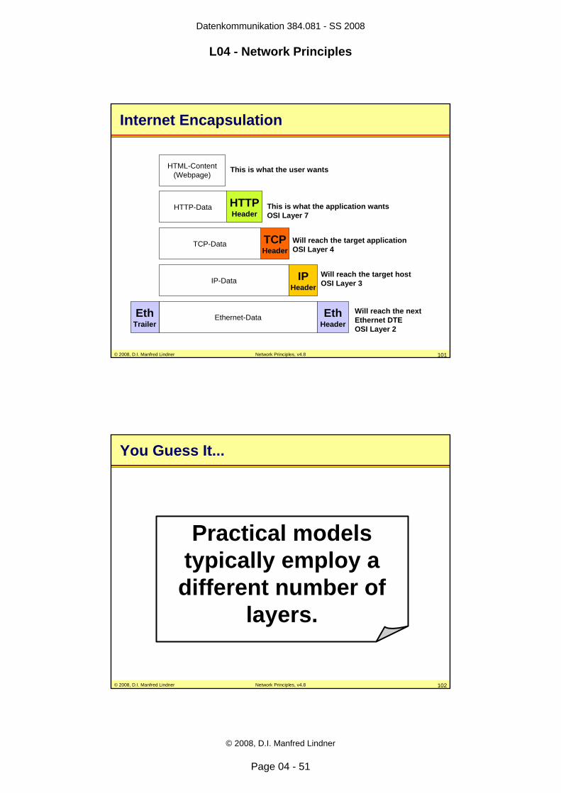
Internet Encapsulation
HTTPHeader
HTTP-Data
HTML-Content(Webpage)
TCPHeader
TCP-Data
IPHeader
IP-Data
Will reach the next Ethernet DTE OSI Layer 2
EthHeader
Ethernet-DataEthTrailer
Will reach the target hostOSI Layer 3
Will reach the target applicationOSI Layer 4
This is what the application wantsOSI Layer 7
This is what the user wants
© 2008, D.I. Manfred Lindner Network Principles, v4.8 102
You Guess It...
Practical models typically employ a different number of
layers.
Page 52
Datenkommunikation 384.081 - SS 2008
L04 - Network Principles
© 2008, D.I. Manfred Lindner
Page 04 - 52
© 2008, D.I. Manfred Lindner Network Principles, v4.8 103
DoD 4-Layer Model (Internet)
Transport Layer
Network Layer
Data Link Layer
Process Layer
Transport Layer
Network Layer
Data Link Layer
Process Layer
"Frame"
„Datagram = CL Packet"
„TCP/UDP Segment"
© 2008, D.I. Manfred Lindner Network Principles, v4.8 104
Practical Encapsulation
Ethernet Frame
IP Packet
TCPSegment
HTTPMessage
HTMLWebpage
Page 53
Datenkommunikation 384.081 - SS 2008
L04 - Network Principles
© 2008, D.I. Manfred Lindner
Page 04 - 53
© 2008, D.I. Manfred Lindner Network Principles, v4.8 105
Agenda
• Introduction• Circuit Switching• Packet Switching
– Principles– Datagram Service– Virtual Call Service
• OSI Reference Model • Summary of Network Methods• Short Introduction of
– IDSN– X.25, Frame Relay, ATM
© 2008, D.I. Manfred Lindner Network Principles, v4.8 106
Taxonomy of Network Technologies
Circuit Switching Packet Switching
DynamicSignalling
StaticConfiguration Datagram Virtual Call
• Deterministic Multiplexing• Low latency (delay)• Designed for isochronous
traffic
• Statistical Multiplexing• Store and forward (variable
delay)• Addressing necessary• Designed for data traffic
ISDN PDHSONET/SDH
IPIPXAppleTalk
X.25Frame RelayATM
Connectionless Connection-orientedQ.931, SS7, ... Manual configuration
Page 54
Datenkommunikation 384.081 - SS 2008
L04 - Network Principles
© 2008, D.I. Manfred Lindner
Page 04 - 54
© 2008, D.I. Manfred Lindner Network Principles, v4.8 107
IP Datagram Service
User A.2
User B.5
R1 R2
R4
R3
R5
Destination Next HopA localB R2C R2
..... .....
A2 B5
A2 B5
A2 B5
Destination Next HopA R1B R4C R3
..... .....
A2
B5
Destination Next HopA R2B R5C R2
..... .....
A2 B5
Destination Next HopA R4B localC R4
..... .....IP address(structured addressNet-ID:Host-ID)
IP HostIP Router
IP RoutingTable of R1
Destination Based Routing
© 2008, D.I. Manfred Lindner Network Principles, v4.8 108
P1
Virtual Call – Call Request (CR)
P1
P2
P3
P0 P0
P1
P2 P0P0 P2
User A.2
User B.5
PS1 PS2 PS3
PS4 PS5
44CRB5A2
Destination Next HopA localB PS2C PS2
..... .....
In OutP0:44 P2:10
P2 P0
10CRB5A2
Destination Next HopA PS1B PS4C PS3
..... .....
In OutP0:10 P3:02
Destination Next HopA PS2B PS5C PS2
..... .....
02C
RB
5A
2
In OutP1:02 P2:69
Destination Next HopA PS4B localC PS4
..... .....
69CRB5A2
In OutP0:69 P2:19
19CRB5A2
RoutingTable of PS1
SwitchingTable of PS1
Page 55
Datenkommunikation 384.081 - SS 2008
L04 - Network Principles
© 2008, D.I. Manfred Lindner
Page 04 - 55
© 2008, D.I. Manfred Lindner Network Principles, v4.8 109
P1
Virtual Call – Call Accepted (CA)
P1
P2
P3
P0 P0
P1
P2 P0P0 P2
User A.2
User B.5
PS1 PS2 PS3
PS4 PS5
P2 P0In OutP0:10 P3:02
02C
AB
5A
2
19 CA B5A2
In OutP0:69 P2:19
In OutP1:02 P2:69
69 CA B5A2
In OutP0:44 P2:10
10 CA B5A244 CA B5A2
© 2008, D.I. Manfred Lindner Network Principles, v4.8 110
Virtual Call – Data Transfer
P1P1
P2
P3
P0 P0
P1
P2 P0P0 P2
User A.2
User B.5
PS1 PS2 PS3
PS4 PS5
P2 P0In OutP0:10 P3:02
In OutP0:69 P2:19
In OutP1:02 P2:69
In OutP0:44 P2:10
44 10
02
69 19
Forwarding performed by switching tables
Page 56
Datenkommunikation 384.081 - SS 2008
L04 - Network Principles
© 2008, D.I. Manfred Lindner
Page 04 - 56
© 2008, D.I. Manfred Lindner Network Principles, v4.8 111
Layer 1 Devices
• Adapts to different physical interfaces• Amplifies and/or refreshes the physical signal• Repeater, Hub (Multiport Repeater),
ISDN NT1, PDH/SDH Muxes
Application
TransportNetworkData LinkPhysical
SessionPresentation
Application
TransportNetworkData LinkPhysical
SessionPresentation
Repeater
© 2008, D.I. Manfred Lindner Network Principles, v4.8 112
Layer 2 Devices
• Filter/Forwards frames according Data Link Layer Address– based on packet switching principle
• Incorporates Layer 1-2• LAN-Bridge (“Ethernet Switch“, L2-Switch)
Application
TransportNetworkData LinkPhysical
SessionPresentation
Application
TransportNetworkData LinkPhysical
SessionPresentation
Bridge
Page 57
Datenkommunikation 384.081 - SS 2008
L04 - Network Principles
© 2008, D.I. Manfred Lindner
Page 04 - 57
© 2008, D.I. Manfred Lindner Network Principles, v4.8 113
Layer 3 Devices
• "Packet Switch" or "Intermediate System"• Forwards packets to other networks according
structured address• Terminates Data Links• Router, WAN-Switch
Application
TransportNetworkData LinkPhysical
SessionPresentation
Application
TransportNetworkData LinkPhysical
SessionPresentation
Router
© 2008, D.I. Manfred Lindner Network Principles, v4.8 114
A Practical Example
Physical(Twisted Pair)
Physical(Serial Line)
Physical(Fiber Ring)
Link(Ethernet)
Link(HDLC)
Link(FDDI)
Network(IP)
Transport(TCP)
NetscapeBrowser
ApacheWebserver
MACAddress
MACAddress
Simple or dummy Address
IP A
ddre
ssIP AddressPo
rt Nu
mbe
rPort Num
ber
What is my destination application?
Where is mydestination network?
Just move this frameto the next NIC
Page 58
Datenkommunikation 384.081 - SS 2008
L04 - Network Principles
© 2008, D.I. Manfred Lindner
Page 04 - 58
© 2008, D.I. Manfred Lindner Network Principles, v4.8 115
Agenda
• Introduction• Circuit Switching• Packet Switching
– Principles– Datagram Service– Virtual Call Service
• OSI Reference Model• Summary of Network Methods• Short Introduction of
– IDSN– X.25, Frame Relay, ATM
© 2008, D.I. Manfred Lindner Network Principles, v4.8 116
ISDN
• Integrated Services Digital Network (ISDN)– offers transport of voice, video and data– all-digital interface at subscriber outlet
• standardized user-to-network interface (UNI)– BRI (Basic Rate Interface)– PRI (Primary Rate Interface)
• implementation of a circuit switching– synchronous TDM– constant delay and constant capacity– channels created on demand (switched)
Page 59
Datenkommunikation 384.081 - SS 2008
L04 - Network Principles
© 2008, D.I. Manfred Lindner
Page 04 - 59
© 2008, D.I. Manfred Lindner Network Principles, v4.8 117
ISDN User-to-Network Interface (UNI)
ISDN-TE
ISDNNetwork Service
physical access link(I.430, I.431)
ISDN-LE
channelfor user data(B-channel)
channelfor signaling(D-channel)
(Q.921, Q.931)
…
logical channels multiplexed on physical channel
© 2008, D.I. Manfred Lindner Network Principles, v4.8 118
Basic Rate Interface (BRI)
– 2 B (bearer) channels with 64 kbit/s each• carrying digitized voice or data
– 1 D (data) channel with 16 kbit/s• for signalling purposes (e.g. Q.931 protocol)
– 2 B and D are synchronous TDM-multiplexed on physical access line
BRI
2 × B
D
TelcoNetwork
144 kbit/s (plus overhead)
ISDNend system ISDN LE
UNI (BRI)
Page 60
Datenkommunikation 384.081 - SS 2008
L04 - Network Principles
© 2008, D.I. Manfred Lindner
Page 04 - 60
© 2008, D.I. Manfred Lindner Network Principles, v4.8 119
Primary Rate Interface (PRI)
– 30 B (Bearer) channels with 64 kbit/s each– 1 D (Data) channel with 64 kbit/s
• for signalling purposes (e.g. Q.931 protocol)
– 30 B and D are synchronous TDM-multiplexed on one physical access line
30 × B
D
PRI 2.048 Mbit/s (E1 Frames)
ISDNend system ISDN LE
UNI (BRI)
© 2008, D.I. Manfred Lindner Network Principles, v4.8 120
Call Setup on D channel via Q.931
Data or Voice Transfer on B channel
Call Release on D channel via Q.931
Procedures
Page 61
Datenkommunikation 384.081 - SS 2008
L04 - Network Principles
© 2008, D.I. Manfred Lindner
Page 04 - 61
© 2008, D.I. Manfred Lindner Network Principles, v4.8 121
I.430I.431
Q.921(LAPD)
Q.931User
Specified
I.430I.431
Q.921(LAPD)
Q.931
Control-Plane(D channel)
User-Plane(B channel)
User-Plane(B channel)
Control-Plane(D channel)
User Network
S/T
1
2
3User
Specified
ITU-T ISDN Layers (“Protocol Stack”)
User-Network-Interface(UNI)
© 2008, D.I. Manfred Lindner Network Principles, v4.8 122
BRI (I.430)
• basic rate interface (S0/T interface)– four wires with terminating resistor (100 ohm)– RJ45 connector with 8 leads
• 2 transmit + 2 receive with power source 1 via phantom circuit• 4 optional power feeds for power source 2 and 3
– modified AMI code (zero causes alternate pulses)• positive or negative pulse of 750mV + -10%• bitstuffing prevent long sequences of ones on D-channel
– frame synchronization based on code violations– frame of 48 bit is transmitted in a period of 250 usec– 192 kbps total speed
• 2 B channels at 64 kbps, 1 D channel at 16 kbps• 48 kbps for framing, DC balancing and D-channel mirroring
Page 62
Datenkommunikation 384.081 - SS 2008
L04 - Network Principles
© 2008, D.I. Manfred Lindner
Page 04 - 62
© 2008, D.I. Manfred Lindner Network Principles, v4.8 123
BRI (I.430)
• basic rate interface (cont.)– allows either a point-to-point or multipoint configuration– point-to-point
• maximum distance between TE and NT is 1000 meters
– for multipoint, physical connection is a passive bus• up to eight TE´s can share a bus• maximum distance between TE and NT is 200 meters (short bus)
or 500 meters (extended bus)
– multipoint operation• B channels are dynamically assigned to TE´s for
exclusive usage only• D channel must be shared by all TE´s in order to
request usage of a B channel• contention mode on D channel
© 2008, D.I. Manfred Lindner Network Principles, v4.8 124
Simplified Frame Structure I.430
F B1
LE to TELE to TE
E D B2 E D B1 E D B2 E D F
F B1 D B2 D B1 D B2 D FTE to LETE to LE
F F …… Starting Delimiter SD for frame Starting Delimiter SD for frame synchronizationsynchronizationD D …… DD--channel bitchannel bitE E …… EchoEcho--channel bitchannel bit
B1 B1 …… 8 B18 B1--channel bitschannel bitsB2 B2 …… 8 B28 B2--channel bitschannel bits
48 bits in 250 microseconds -> 192 kbps
Page 63
Datenkommunikation 384.081 - SS 2008
L04 - Network Principles
© 2008, D.I. Manfred Lindner
Page 04 - 63
© 2008, D.I. Manfred Lindner Network Principles, v4.8 125
D - Channel Access Control
• D - channel – must be shared by different TEs in a multipoint
configuration– control of access to D channel is necessary
• control is done via E - bits– TEs use D - bits for transmission to NT– E contains echo (sent by NT) of D bit received by NT– note:
• encoding gives transmitted zeros higher priority than ones (zeros produce signal changes (pulses) but ones do not)
• if TEs send at the same time on D channel, only TE with the most zeros transmitted will see its message on E again
© 2008, D.I. Manfred Lindner Network Principles, v4.8 126
D - Channel Access Control
• before TE can use D channel– at least eight ones (no signal activity) in sequence must be
received (carrier sense, monitor state)
• when TE starts transmitting on D channel– E bits are used for comparison transmitted information
with received information– if unequal (collision detect) TE will stop transmission
(collision resolution) and will listen for next eight ones in sequence
Page 64
Datenkommunikation 384.081 - SS 2008
L04 - Network Principles
© 2008, D.I. Manfred Lindner
Page 04 - 64
© 2008, D.I. Manfred Lindner Network Principles, v4.8 127
D - Channel Access Control
• once the D channel was successfully occupied– bitstuffing will prevent sequence of eight ones for the rest
of the message and TE can finish its transmission without disturbance
• to give other TEs fair chance to access the D channel– TE must release D channel after message was sent– TE waits then for a sequence of nine ones before access
is tried again– this allows other waiting TEs access to the D channel
• round-robin among all TEs in worst case
© 2008, D.I. Manfred Lindner Network Principles, v4.8 128
PRI (I.431)
• primary rate interface– allows point-to-point configuration only– based on E1 or T1 specifications– E1 (HDB3 encoding)
• 2.048 Mbps total speed• timeslot 0 used for synchronization• timeslot 16 used for D channel information• timeslots 1-15 and 17-31 for 30 B-channels
Page 65
Datenkommunikation 384.081 - SS 2008
L04 - Network Principles
© 2008, D.I. Manfred Lindner
Page 04 - 65
© 2008, D.I. Manfred Lindner Network Principles, v4.8 129
ISDN Data Link Layer Q.921 for Signaling
• only used on the D channel• uses LAPD
– Link Access Procedure D-Channel– based on HDLC– 2 byte address field– may use extended sequence numbering (0-127)
• ISDN level 3 signaling– travels in the information field of the LAPD I-frame
• LAPD may also be used to support user traffic– D channel is not fully utilized by signaling messages– e.g. X.25 over D-channel
© 2008, D.I. Manfred Lindner Network Principles, v4.8 130
Flag8 7 6 5 4 3 2 1
SAPI C/R EA
TEI EA
Control
Information
FCSFlag
byte 1
byte 2
byte 3
byte 4-5
address
EA Address Field Extension BitC/R Command/Response BitSAPI Service Access Point IdentifierTEI Terminal Endpoint Identifier
Data Link Connection Identifier (DLCI)
EA = 0 −> address octet followsEA = 1 −> last address octet
C/R = 1 Command ( Network −> User )C/R = 0 Response ( Network −> User )User -> Network ... vice versa
LAPD Frame Format
Page 66
Datenkommunikation 384.081 - SS 2008
L04 - Network Principles
© 2008, D.I. Manfred Lindner
Page 04 - 66
© 2008, D.I. Manfred Lindner Network Principles, v4.8 131
SAPI and TEI
• SAPI - Service Access Point Identifier– identifies the entity where data link layer services are
provided to the layer above– protocol type field– examples
• 0 signaling information (s-type)• 16 packet data (p-type)• 63 management information
• TEI - Terminal Endpoint Identifier– identifies an endpoint within a service access point– “address field” of HDLC– possible values
• 0 - 127
© 2008, D.I. Manfred Lindner Network Principles, v4.8 132
ISDN Network Layer Q.931 for Signaling
• not used on B channels• Q.931 is used on D channels for call control
– used between TE and local ISDN switch– not used end-to-end
• Signaling System 7 (SS#7) is used inside the network between ISDN-LEs
• several flavors exist on the market– be careful to select the correct version of the protocol
Page 67
Datenkommunikation 384.081 - SS 2008
L04 - Network Principles
© 2008, D.I. Manfred Lindner
Page 04 - 67
© 2008, D.I. Manfred Lindner Network Principles, v4.8 133
InformationElements
Protocol Discriminator
F Call ReferenceMessage Type
8 7 6 5 4 3 2 1
Call Ref. Length0 0 0 0
0
08 7 6 5 4 3 2 1
Information Element IdentifierInformation Element Length
Contents of Information Element
Q.931 FormatQ.931 Format Information ElementInformation Element
Protocol discriminator(0x08 except 1TR6: 0x41)Call reference (random number)Call reference flag F(bit 8 ... 0 origin, 1 response)
Q.931 Protocol Format
© 2008, D.I. Manfred Lindner Network Principles, v4.8 134
Layer 3 Messages
• Call Establishment– ALERTing– CALL PROCeeding– CONNect
• CONNect ACKnowledge– SETUP
• SETUP ACKnowledge
• Call Information Phase– RESume
• RESume ACKnowlegde• RESume REJect
– SUSPend• SUSPend ACKnowledge• SUSPend REJect
– USER INFOrmation
• Call Clearing– DETatch
• DETach ACKnowledge– DISConnect– RELease
• RELease COMplete– REStart
• REStart ACKnowledge
• Miscellaneous– CANCel, - Ack, - Reject– CONgestion CONtrol– FACility, - Ack, - Reject– INFOrmation– REGister. - Ack, - Reject– STATUS
Page 68
Datenkommunikation 384.081 - SS 2008
L04 - Network Principles
© 2008, D.I. Manfred Lindner
Page 04 - 68
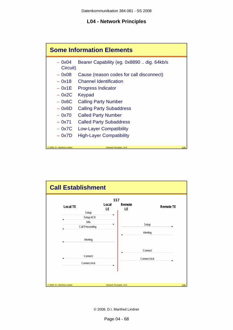
© 2008, D.I. Manfred Lindner Network Principles, v4.8 135
Some Information Elements
– 0x04 Bearer Capability (eg. 0x8890 .. dig. 64kb/s Circuit)
– 0x08 Cause (reason codes for call disconnect)– 0x18 Channel Identification– 0x1E Progress Indicator– 0x2C Keypad– 0x6C Calling Party Number– 0x6D Calling Party Subaddress– 0x70 Called Party Number– 0x71 Called Party Subaddress– 0x7C Low-Layer Compatibility– 0x7D High-Layer Compatibility
© 2008, D.I. Manfred Lindner Network Principles, v4.8 136
Local TESetup
Local LE Remote TE
Call ProceedingSetup
Alerting
Alerting
Connect
Connect
Connect AckConnect Ack
Call Establishment
Setup ACKInfo
Remote LE
SS7
Page 69
Datenkommunikation 384.081 - SS 2008
L04 - Network Principles
© 2008, D.I. Manfred Lindner
Page 04 - 69
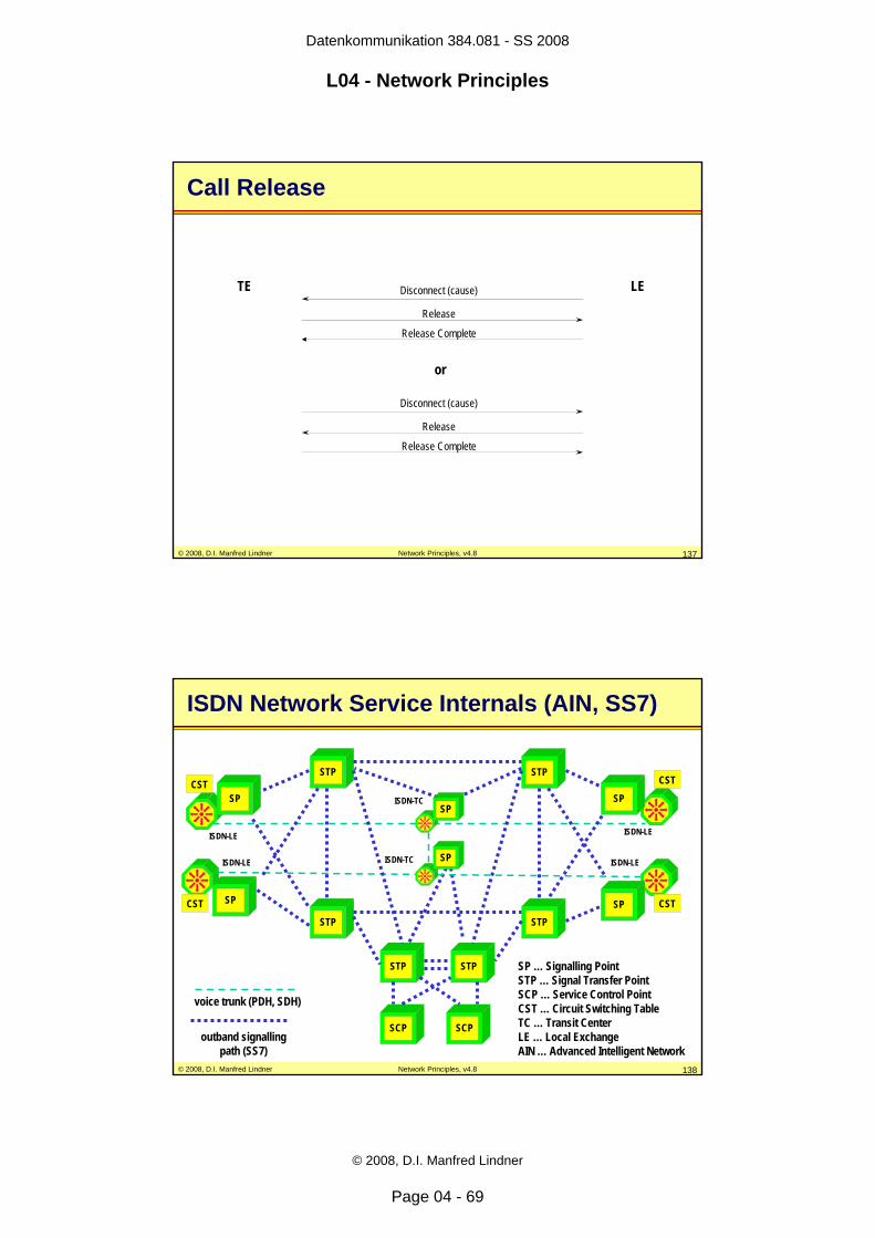
© 2008, D.I. Manfred Lindner Network Principles, v4.8 137
TE LEDisconnect (cause)
Release
Release Complete
Disconnect (cause)
Release
Release Complete
or
Call Release
© 2008, D.I. Manfred Lindner Network Principles, v4.8 138
ISDN Network Service Internals (AIN, SS7)
STP
STP STP
STP
STP STP
SCP SCP
SP
SP
SP
SP
voice trunk (PDH, SDH)
outband signallingpath (SS7)
SP … Signalling Point STP … Signal Transfer PointSCP … Service Control PointCST … Circuit Switching TableTC … Transit CenterLE … Local ExchangeAIN … Advanced Intelligent Network
CST
CST CST
CST
ISDN-LE
ISDN-LE ISDN-LE
ISDN-LE
ISDN-TC
ISDN-TCSP
SP
Page 70
Datenkommunikation 384.081 - SS 2008
L04 - Network Principles
© 2008, D.I. Manfred Lindner
Page 04 - 70
© 2008, D.I. Manfred Lindner Network Principles, v4.8 139
ISDN Detail Information
• For a detailed description of ISDN see the corresponding appendix chapter
© 2008, D.I. Manfred Lindner Network Principles, v4.8 140
Agenda
• Introduction• Circuit Switching• Packet Switching
– Principles– Datagram Service– Virtual Call Service
• OSI Reference Model • Summary of Network Methods• Short Introduction of
– IDSN– X.25, Frame Relay, ATM
Page 71
Datenkommunikation 384.081 - SS 2008
L04 - Network Principles
© 2008, D.I. Manfred Lindner
Page 04 - 71
© 2008, D.I. Manfred Lindner Network Principles, v4.8 141
What is X.25?
• packet switching technology– based on store-and-forward of packets– connection oriented
• interface definition between user and network equipment– X.25 - DTE (e.g. router) <−> X.25 - DCE (packet switch)
• wide area network service – based on virtual circuit technique
• operation within X.25 network cloud– switch to switch communication not standardized– vendor specific implementation
© 2008, D.I. Manfred Lindner Network Principles, v4.8 142
X.25 - DTE
X.25 - DTE
SNACC
SNAFEP X.25 - DTE
X.25 - DCE
X.25 network
User to Network Interface
physical access link
X.25 - DCE
X.25 - DCE
X.25 - DTE
X.25 - DTEX.25 - DCE
X.25 Topology
Page 72
Datenkommunikation 384.081 - SS 2008
L04 - Network Principles
© 2008, D.I. Manfred Lindner
Page 04 - 72
© 2008, D.I. Manfred Lindner Network Principles, v4.8 143
X.25 Virtual Circuits/LCN
• virtual circuit technique – for statistically multiplexing many logical data
conversations over a single physical transmission link – end systems (X.25-DTE) use virtual circuits for delivering
data to the X.25 network and vice versa– virtual circuits appear to end systems as transparent
transport pipes (logical point-to-point connections)
• virtual circuits (VCs) are identified using LCN numbers– logical channel number (LCN)– LCN are of local significance only
© 2008, D.I. Manfred Lindner Network Principles, v4.8 144
SNACC
SNAFEP
LCN=100
LCN=200
LCN=300
LCN=400
LCN=500
LCN=100
LCN=300
LCN=200
local significanceof LCNs !!!
Logical Channel Number (LCN)
Page 73
Datenkommunikation 384.081 - SS 2008
L04 - Network Principles
© 2008, D.I. Manfred Lindner
Page 04 - 73
© 2008, D.I. Manfred Lindner Network Principles, v4.8 145
PVC
PVC PVC
Permanent Virtual Circuit (PVC)
• static connection between two end devices
• functionally equivalent to dedicated leased lines
• but remember– store and forward technology– variable delays
© 2008, D.I. Manfred Lindner Network Principles, v4.8 146
No Connection
Data
Connection Established
SVC
Data
Connection Closed
Data
t0 t1 t2
Switched Virtual Circuit (SVC)
• dynamic connection setup and tear down between two end devices
• similar to dial up circuits in that they provide bandwidth on demand
Page 74
Datenkommunikation 384.081 - SS 2008
L04 - Network Principles
© 2008, D.I. Manfred Lindner
Page 04 - 74
© 2008, D.I. Manfred Lindner Network Principles, v4.8 147
Roots of X.25
• originally defined by CCITT – as an interface between user equipment and public
switched data network– three layers covered
• X.21 (physical layer)• LAPB (data link layer); a member of the HDLC layer• X.25 (network layer)
– different versions:• four years cycle• 1980 (yellow books), 1984 (red books), 1988 (blue book), ...
• X.25 definitions were expanded by ISO– for provisioning the Connection Mode Network Service
(layer 3) in OSI based networks
© 2008, D.I. Manfred Lindner Network Principles, v4.8 148
Physical(X.21, X.21 bis)
Data Link(LAPB)
Network(X.25 PLP)
Upper Layers
F A C I FCS F
P U
UUser Data
Packet
LAPB Frame
X.25 Layers (CCITT)
Page 75
Datenkommunikation 384.081 - SS 2008
L04 - Network Principles
© 2008, D.I. Manfred Lindner
Page 04 - 75
© 2008, D.I. Manfred Lindner Network Principles, v4.8 149
7 - 4 3 2 1 DCE
X.25 - DTE X.25 - DCE
X.25 - DTE
X.25 - DCEphysical layer X.21
data link layer LAPB
network layer X.25 PLP
upper layers (end-to-end)
X.25 modem X.25 switch
X.25 Interface (CCITT)
© 2008, D.I. Manfred Lindner Network Principles, v4.8 150
X.25 Facts
• remember:– X.25 standards defines communication between
DTE and DCE only– operation (e.g. routing) within network not defined– only sequencing must be guaranteed– X.25 uses statistical multiplexing
• X.25 technology was developed for low quality,low speed lines– use error recovery and flow control on layer 2
to control transmission of frames over physical line– use flow control and optionally error recovery on layer 3
to control transmission of packets over a virtual circuit
Page 76
Datenkommunikation 384.081 - SS 2008
L04 - Network Principles
© 2008, D.I. Manfred Lindner
Page 04 - 76
© 2008, D.I. Manfred Lindner Network Principles, v4.8 151
X.25 Detail Information
• For a detailed description of X.25 see the corresponding appendix chapter
© 2008, D.I. Manfred Lindner Network Principles, v4.8 152
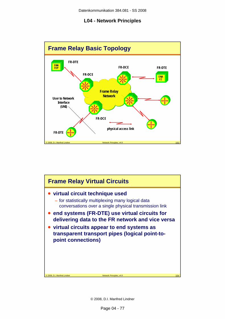
What is Frame Relay?
• packet switching technology– based on store-and-forward of packets– connection oriented
• interface definition between user and network equipment– FR-DTE (e.g. router) <−> FR-DCE (frame relay switch)– UNI (User to Network Interface)
• wide area network service – based on virtual circuit technique
• operation within FR network cloud– switch to switch communication not standardized– vendor specific implementation
Page 77
Datenkommunikation 384.081 - SS 2008
L04 - Network Principles
© 2008, D.I. Manfred Lindner
Page 04 - 77
© 2008, D.I. Manfred Lindner Network Principles, v4.8 153
FR-DTE
FR-DTE
SNACC
SNAFEP FR-DTE
FR-DCE
Frame RelayNetworkUser to Network
Interface(UNI)
physical access link
FR-DCE
FR-DCE
Frame Relay Basic Topology
© 2008, D.I. Manfred Lindner Network Principles, v4.8 154
Frame Relay Virtual Circuits
• virtual circuit technique used – for statistically multiplexing many logical data
conversations over a single physical transmission link • end systems (FR-DTE) use virtual circuits for
delivering data to the FR network and vice versa• virtual circuits appear to end systems as
transparent transport pipes (logical point-to-point connections)
Page 78
Datenkommunikation 384.081 - SS 2008
L04 - Network Principles
© 2008, D.I. Manfred Lindner
Page 04 - 78
© 2008, D.I. Manfred Lindner Network Principles, v4.8 155
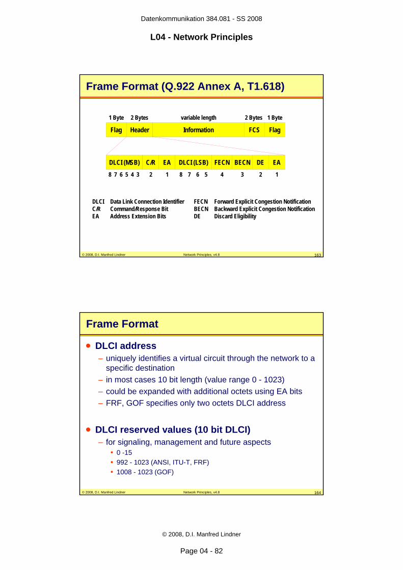
Frame Relay DLCI
• virtual circuits (VCs) are identified using DLCI numbers– data link connection identifier (DLCI), locally significant
• some implementations support global addressing– still locally significant– but number of user ports limited
• two kinds of virtual circuits– permanent virtual circuits (PVC) established in advance by
service provider– switched virtual circuits (SVC) established on demand by
user through signaling procedure
© 2008, D.I. Manfred Lindner Network Principles, v4.8 156
SNACC
SNAFEP
DLCI=100
DLCI=200
DLCI=300
DLCI=200
DLCI=500
DLCI=100
DLCI=300
DLCI=200
local significanceof DLCI´s!!!
Data Link Connection Identifier (DLCI)
Page 79
Datenkommunikation 384.081 - SS 2008
L04 - Network Principles
© 2008, D.I. Manfred Lindner
Page 04 - 79
© 2008, D.I. Manfred Lindner Network Principles, v4.8 157
Frame Relay versus X.25
• protocols like X.25 have been developed for low quality, low speed lines– use error recovery and flow control on layer 2 and 3
• those protocols are an overkill for high speed lines providing very low error rates
• frame relay has been designed to overcome these problems– use only part of layer 2 – error recovery moved to the end system– congestion control instead of flow control– therefore simpler link operation and hence higher speed
and throughput then X.25 is possible
© 2008, D.I. Manfred Lindner Network Principles, v4.8 158
Roots of Frame Relay
• originally defined by ITU-T as a network service within ISDN– I.122 specifies the framework for additional packet mode
bearer services, one of these services is frame relay– initial requirement was for ISDN primary rate access
• frame relay is based upon ISDN data link layer procedures for the D channel – D channel is used for ISDN signaling and ISDN data
transfer in packet switching mode – I.440/I.441 ISDN user-network interface data link layer– Q.920/Q.921 link access procedures on the D channel
(LAPD)
Page 80
Datenkommunikation 384.081 - SS 2008
L04 - Network Principles
© 2008, D.I. Manfred Lindner
Page 04 - 80
© 2008, D.I. Manfred Lindner Network Principles, v4.8 159
Control Plane <-> User Plane
FR-DTE
Frame RelayNetwork
physical access link
FR-DCE
virtual circuitfor user data
virtual circuitfor signalling / LMI
protocols describedby user plane
protocols describedby control plane
(out-band signalling)
logical channels multiplexed on physical channel
© 2008, D.I. Manfred Lindner Network Principles, v4.8 160
I.430I.431
Q.922DL-core(LAPF)
Q.933Annex A
Q.922 DL-core(LAPF)
UserSpecified
I.430I.431
Q.922DL-core(LAPF)
Q.933Annex A
Q.922 DL-core(LAPF)
C-Plane(PVC-LMI)
U-Plane(PVC)
User Network
S/T
1
2
3 UserSpecified
ITU-T Frame Relay Protocol Architecture
U-Plane(User Plane)
C-Plane(ControlPlane)
Page 81
Datenkommunikation 384.081 - SS 2008
L04 - Network Principles
© 2008, D.I. Manfred Lindner
Page 04 - 81
© 2008, D.I. Manfred Lindner Network Principles, v4.8 161
I.430I.431
Q.922DL-control
Q.933
Q.922 DL-core(LAPF)
UserSpecified
I.430I.431
Q.922DL-control
Q.933
Q.922 DL-core(LAPF)
C-Plane(SVC-Setup)
U-Plane(SVC)
U-Plane(User Plane)
C-Plane(ControlPlane)
User Network
S/T
1
2
3 UserSpecified
ITU-T Frame Relay Protocol Architecture
© 2008, D.I. Manfred Lindner Network Principles, v4.8 162
Frame Relay Layer 2 for Data Transfer
• data link layer (2) defined in Q.922 Annex A (LAPF) or T1.618 specifies– frame alignment and delimiting (HDLC Flag)– zero bit insertion and extraction (bit stuffing)– error detection but no correction– verification that frame fulfill minimum size, maximum
agreed size, integral number of octets– frame multiplexing/demultiplexing using an address field
(DLCI number)– congestion control
• all remaining upper layers are transparent to the frame relay user plane
Page 82
Datenkommunikation 384.081 - SS 2008
L04 - Network Principles
© 2008, D.I. Manfred Lindner
Page 04 - 82
© 2008, D.I. Manfred Lindner Network Principles, v4.8 163
Flag Header Information FCS Flag
DLCI (MSB) C/R EA DLCI (LSB) FECN BECN DE EA
1 Byte 2 Bytes variable length 2 Bytes 1 Byte
1234128 7 6 5 4 3 8 7 6 5
DLCI Data Link Connection Identifier FECN Forward Explicit Congestion NotificationC/R Command/Response Bit BECN Backward Explicit Congestion NotificationEA Address Extension Bits DE Discard Eligibility
Frame Format (Q.922 Annex A, T1.618)
© 2008, D.I. Manfred Lindner Network Principles, v4.8 164
Frame Format
• DLCI address– uniquely identifies a virtual circuit through the network to a
specific destination– in most cases 10 bit length (value range 0 - 1023)– could be expanded with additional octets using EA bits– FRF, GOF specifies only two octets DLCI address
• DLCI reserved values (10 bit DLCI)– for signaling, management and future aspects
• 0 -15• 992 - 1023 (ANSI, ITU-T, FRF)• 1008 - 1023 (GOF)
Page 83
Datenkommunikation 384.081 - SS 2008
L04 - Network Principles
© 2008, D.I. Manfred Lindner
Page 04 - 83
© 2008, D.I. Manfred Lindner Network Principles, v4.8 165
Frame Format
• Forward Explicit Congestion Notification (FECN)– may be set by a frame relay network to notify the user that
congestion was experienced for traffic in the direction of the frame carrying FECN indication
• Backward Explicit Congestion Notification (BECN)– may be set by a frame relay network to notify the user that
congestion was experienced by traffic in the opposite direction of the frame carrying BECN indication
• DE Discard Eligibility– may be set by the user or the network to indicate that this
frame should be discarded in preference to other frames (without the DE bit set) in case of congestion
© 2008, D.I. Manfred Lindner Network Principles, v4.8 166
Congestionon outgoing link
FR-DTE FR-DTE
virtual circuit
..... INFO, FECN = 1BECN = 1, INFO .....
FECN/BECN
Page 84
Datenkommunikation 384.081 - SS 2008
L04 - Network Principles
© 2008, D.I. Manfred Lindner
Page 04 - 84
© 2008, D.I. Manfred Lindner Network Principles, v4.8 167
FR Data Link Layer Service
• LAPF/T1.618 does not provide any error recovery or flow control procedures
• although frame relay is connection oriented – only a best effort service is offered to end systems
• only delivering frames in sequence is offered to end systems– basic transport service
• principle rule:– a frame relay network tries to guarantee delivering frames
which are inside the traffic contract with high probability
© 2008, D.I. Manfred Lindner Network Principles, v4.8 168
FR Data Link Layer Service
• if a frame error is detected by a frame relay switch– the corresponding frame will be discarded
• if a congestion situation is experienced by a frame relay switch (buffer overflow)– frames will be discarded
• error recovery must be done by end systems– end systems must detect missing frames using their own
higher layer sequence numbers– discarded frames must be retransmitted by end systems
Page 85
Datenkommunikation 384.081 - SS 2008
L04 - Network Principles
© 2008, D.I. Manfred Lindner
Page 04 - 85
© 2008, D.I. Manfred Lindner Network Principles, v4.8 169
Frame Relay Detail Information
• For a detailed description of Frame Relay see the corresponding appendix chapter
© 2008, D.I. Manfred Lindner Network Principles, v4.8 170
What is ATM?
• ATM– Asynchronous Transfer Mode– Based on asynchronous TDM
• hence buffering and address information is necessary
• Cell switching technology– based on store-and-forward of cells– connection oriented type of service
• ATM cell– small packet with constant length– 53 bytes long
• 5 bytes header + 48 bytes data
Page 86
Datenkommunikation 384.081 - SS 2008
L04 - Network Principles
© 2008, D.I. Manfred Lindner
Page 04 - 86
© 2008, D.I. Manfred Lindner Network Principles, v4.8 171
What is Asynchronous Transfer Mode?
Synchronous TDMSynchronous TDM(+) Constant delay
(good for voice)
(+) Protocol transparent
(–) Fixed channel assignment (might be uneconomic)
(–) Trunk bandwidth = sum of channel speeds (expensive)
Asynchronous TDMAsynchronous TDM(–) Variable delay
(variable frame sizes)
(+/~) Fairly protocol transparent
(+) Flexible channel assignment (using addresses)
(+) Trunk bandwidth = average of channel speeds
Asynchronous Transfer Mode (ATM)Asynchronous Transfer Mode (ATM)(+) Bounded delay through fixed cell sizes (53 bytes)
(+) Protocol transparent through higher layers (CPCS and SAR)
(+) Flexible channel assignment using addresses (VPI/VCI)
(+) Trunk bandwidth according average channel speeds(different traffic classes)
© 2008, D.I. Manfred Lindner Network Principles, v4.8 172
Design Ideas
Asynchronous TDM
Best trunk utilization
Synchronous TDMFast Switching and short delays
through constant timeslots
Flexible channel assignmentthrough addresses
Protocol Transparent
ATM
copy
copy
emulate
emulate
Solved through constant packet sizes and intelligent traffic
management based on traffic classes
Solved through adaptation layers
Page 87
Datenkommunikation 384.081 - SS 2008
L04 - Network Principles
© 2008, D.I. Manfred Lindner
Page 04 - 87
© 2008, D.I. Manfred Lindner Network Principles, v4.8 173
Synchronous Transfer Mode
I 1
I 2...
I n
O 1
O 2...
O q
2 1 10 3 2 1
I1
1
3
10 9 81
6 5 47
10
1 10 9 8
8 7 6 5
O2 82 O7 33 O1 34 O4 5
Incoming Connection Timeslot
Outgoing Connection Timeslot
.................. .....................
Fixed Fixed timeslot timeslot
allocation !allocation !
TimeslotsExample: 1 Frame consists of 10 timeslots (1..10)
© 2008, D.I. Manfred Lindner Network Principles, v4.8 174
Asynchronous Transfer Mode
I 1
I 2...
I n
O 1
O 2...
O q
I1
v O2 aw O7 bx O1 cy O4 d
Incoming Connection Header
Outgoing Connection Header
.................. .....................
Cell header: addressing information for routing and dynamic bandwidth allocation
Cell
x y x z
u v y u
y z z z
a c c b
b d a a
c c c a
Data Header
Page 88
Datenkommunikation 384.081 - SS 2008
L04 - Network Principles
© 2008, D.I. Manfred Lindner
Page 04 - 88
© 2008, D.I. Manfred Lindner Network Principles, v4.8 175
Why Cells?
• Cell switching technology allows– Forwarding of cells in hardware
• Hence very fast
– Predictable and bounded delay for a given cell• Still variable !
– Quality of Service (QoS) guarantees• With specific strategies like admission control, QOS routing, traffic
shaping, traffic policing, cell scheduling
– Integration of voice, video and data• Real-time traffic and non real-time traffic on the same network
infrastructure
© 2008, D.I. Manfred Lindner Network Principles, v4.8 176
Cell Switching and Jitter
Voice and FTP over Tradtional Packet Switching
Constant/Bounded delay possible with ATM
Delay variations (!)
variable packet lengths
constant packet lengths
Page 89
Datenkommunikation 384.081 - SS 2008
L04 - Network Principles
© 2008, D.I. Manfred Lindner
Page 04 - 89
© 2008, D.I. Manfred Lindner Network Principles, v4.8 177
ATM Technology
• WAN service and campus area network service– Based on virtual circuit technique – Connection oriented, enables charging for carriers and
providers– Sequencing of cell stream is guaranteed
but no error recovery is done for damaged cells– One single technology to cover both WAN and LAN (MAN)
aspects• Standardized interface definitions
– User Network Interface (UNI) • between ATM-DTE and ATM-DCE
– Network Node Interface (NNI)• between ATM-DCE and ATM-DCE
© 2008, D.I. Manfred Lindner Network Principles, v4.8 178
ATM-DTE
SNACC
SNAFEP
User NetworkInterface
(UNI)
physical access link
ATM-DCE
ATM Basic Topology
ATM-DTE
ATM-DTE
ATM-DCE
ATM-DCE
ATM trunk link
Network Node Interface(NNI)
ATM-DTE
ATM-DTE
ATM-DCE
ATM-DCE
Page 90
Datenkommunikation 384.081 - SS 2008
L04 - Network Principles
© 2008, D.I. Manfred Lindner
Page 04 - 90
© 2008, D.I. Manfred Lindner Network Principles, v4.8 179
ATM VPI / VCI
• Virtual circuits (VCs) are identified using VPI / VCI numbers– Virtual Path Identifier / Virtual Channel Identifier– Only locally significant
• Two kinds of virtual circuits– Permanent virtual circuits (ATM-PVC) established in
advance by service provider– Switched virtual circuits (ATM-SVC) established on
demand by user through signaling procedure
© 2008, D.I. Manfred Lindner Network Principles, v4.8 180
SNACC
SNAFEP
VPI/VCI = 0/50 (A->B)
local significanceof VPI/VCIs !!!!
VPI / VCI
VPI/VCI = 0/200
VPI/VCI = 0/44
VPI/VCI = 0/200
VPI/VCI = 0/200
VPI/VCI = 0/99VPI/VCI = 0/100
VPI/VCI = 0/88 (D->C)
12
43
A
B
CD
Page 91
Datenkommunikation 384.081 - SS 2008
L04 - Network Principles
© 2008, D.I. Manfred Lindner
Page 04 - 91
© 2008, D.I. Manfred Lindner Network Principles, v4.8 181
1 2
43
I1
ATM Switching Tables
I1: 0/88 O2: 0/77
from to
I4: 0/99 O2: 0/44
from to
I1: 0/77 O2: 0/99I4: 0/77 O3: 4/88
from to
SNACC
SNAFEPA
O3I1 O2 I4
O2
I4O3
I1 O3
I1: 0/50 O3: 0/77
from to
B
CDI1: 4/88 O3: 2/99
from to
I1O2
Switching Tableof ATM Switch 2
© 2008, D.I. Manfred Lindner Network Principles, v4.8 182
Cell Forwarding / Label Swapping 1
I1
I1: 0/88 O2: 0/77
from to
I4: 0/99 O2: 0/44
from to
I1: 0/77 O2: 0/99I4: 0/77 O3: 4/88
from to
SNACC
SNAFEPA
O3I1 O2 I4
O2
I4O3
I1 O3
I1: 0/50 O3: 0/77
from to
B
CDI1: 4/88 O3: 2/99
from to
I1O2
...Cell Header (5 Byte) … Payload (48 byte)
0 50
VPI / VCI
0 88
Page 92
Datenkommunikation 384.081 - SS 2008
L04 - Network Principles
© 2008, D.I. Manfred Lindner
Page 04 - 92
© 2008, D.I. Manfred Lindner Network Principles, v4.8 183
Cell Forwarding / Label Swapping 2
1 2
43
I1
I1: 0/88 O2: 0/77
from to
I4: 0/99 O2: 0/44
from to
I1: 0/77 O2: 0/99I4: 0/77 O3: 4/88
from to
SNACC
SNAFEPA
O3I1 O2 I4
O2
I4O3
I1 O3
I1: 0/50 O3: 0/77
from to
B
CDI1: 4/88 O3: 2/99
from to
I1O2
0 77
0 77
© 2008, D.I. Manfred Lindner Network Principles, v4.8 184
Cell Forwarding / Label Swapping 3
1 2
43
I1
I1: 0/88 O2: 0/77
from to
I4: 0/99 O2: 0/44
from to
I1: 0/77 O2: 0/99I4: 0/77 O3: 4/88
from to
SNACC
SNAFEPA
O3I1 O2 I4
O2
I4O3
I1 O3
I1: 0/50 O3: 0/77
from to
B
CDI1: 4/88 O3: 2/99
from to
I1O2
0 99
4 88
Page 93
Datenkommunikation 384.081 - SS 2008
L04 - Network Principles
© 2008, D.I. Manfred Lindner
Page 04 - 93
© 2008, D.I. Manfred Lindner Network Principles, v4.8 185
Cell Forwarding / Label Swapping 4
1 2
43
I1
I1: 0/88 O2: 0/77
from to
I4: 0/99 O2: 0/44
from to
I1: 0/77 O2: 0/99I4: 0/77 O3: 4/88
from to
SNACC
SNAFEPA
O3I1 O2 I4
O2
I4O3
I1 O3
I1: 0/50 O3: 0/77
from to
B
CDI1: 4/88 O3: 2/99
from to
I1O2
0 44
2 99
© 2008, D.I. Manfred Lindner Network Principles, v4.8 186
Segmentation Principle
• Cells are much smaller than data packets– Segmentation and Reassembly is necessary in ATM DTEs (!!!)– ATM DCEs are not involved in that
H TSDU
Datagram
BOM COM COM COM COM EOM PAD
Bitstream
44 Octet48
H Payload H Payload H Payload5
H T
44 44 44 44 44 44
44 OctetH T
Page 94
Datenkommunikation 384.081 - SS 2008
L04 - Network Principles
© 2008, D.I. Manfred Lindner
Page 04 - 94
© 2008, D.I. Manfred Lindner Network Principles, v4.8 187
ATM Usage
• Public and private networks– LAN, MAN, WAN
• Backbone high-speed networks– Public (Telco's) or private
• Original goal: World-wide ATM network – But Internet technology and state-of-the art Ethernet are
more attractive today• New importance as backbone technology for
mobile applications– Cellular networks for GSM, GPRS, UMTS, ...
© 2008, D.I. Manfred Lindner Network Principles, v4.8 188
ATM as WAN Technology based on SDH
RSDH R R SDH
ISDNLE
POTSLE
PABX
ISDNLE
POTSLE
PABXPRI / E12Mb/s
PRI / E1
E334Mb/s
E3 E3STM--4
622Mb/s
STM-1155Mb/s
STM-1155Mb/s
up to hundreds of km´s
E334Mb/s
…….
Page 95
Datenkommunikation 384.081 - SS 2008
L04 - Network Principles
© 2008, D.I. Manfred Lindner
Page 04 - 95
© 2008, D.I. Manfred Lindner Network Principles, v4.8 189
SDH Circuits (Timeslots of S-TDM)
RSDH R R SDH
ISDNLE
POTSLE
PABX
ISDNLE
POTSLE
PABXPRI / E12Mb/s
PRI / E1
E334Mb/s E3 E3
STM--4622Mb/s
STM-1155Mb/s
STM-1155Mb/s
E334Mb/s
SDH-Circuit 1 for 34Mb/s
SDH-Circuit 2 for 34Mb/s
…….
SDH-Circuit 3 for 155Mb/s
© 2008, D.I. Manfred Lindner Network Principles, v4.8 190
ATM-VC´s inside SDH-Circuit
RSDH R R SDH
ISDNLE
POTSLE
PABX
ISDNLE
POTSLE
PABXPRI / E12Mb/s
PRI / E1
E334Mb/s E3 E3
STM--4622Mb/s
STM-1155Mb/s
STM-1155Mb/s
E334Mb/s
SDH-Circuit 1 for 34Mb/s
SDH-Circuit 2 for 34Mb/s
…….
SDH-Circuit 3 for 155Mb/s
ATM as Intelligent BandwidthManagement System
ATM-VC1
ATM-VC2
ATM-VC3
Page 96
Datenkommunikation 384.081 - SS 2008
L04 - Network Principles
© 2008, D.I. Manfred Lindner
Page 04 - 96
© 2008, D.I. Manfred Lindner Network Principles, v4.8 191
ATM as LAN/ MAN Technology based on Dark Fiber
up to some km´sup to some 100m´s up to some 100m´s
Dark Fiber
© 2008, D.I. Manfred Lindner Network Principles, v4.8 192
ATM Reference Model
• User Plane– Provides for transfer of information
• Control Plane– Call control, connection control, PVC management,
interim local management interface (e.g. ILMI)• Management Plane
– Layer management• e.g. meta-signaling, layer specific Operation and Maintenance
(OAM) information flow
– Plane management• Management functions related to the whole system• Coordination between all planes
Page 97
Datenkommunikation 384.081 - SS 2008
L04 - Network Principles
© 2008, D.I. Manfred Lindner
Page 04 - 97
© 2008, D.I. Manfred Lindner Network Principles, v4.8 193
Control Plane <-> User Plane
ATM-DTE
Physical access link
ATM-DCE
Virtual circuitfor user data
Virtual circuitfor signaling / ILMI / routing
User plane describes protocols used between ATM DTEs on transport pipe
Control plane describes protocolsused between ATM DTE and ATM DCE
or between ATM DCE and ATM DCE
VPI/VCI = 0/5(e.g. Q.2931 signalling)
ATM-DCE
VPI/VCI = 0/18(e.g. PNNI Routing)
ATM-DTE
VPI/VCI = 0/5(e.g. PNNI Signalling)
© 2008, D.I. Manfred Lindner Network Principles, v4.8 194
Signalingand
Control
Class AConstantBit RateCircuit
Emulation
Class BVariableBit RateAudio/Video
Class CConn.
OrientedServicesfor Data
Class DConn.Less
Servicesfor Data
AdaptationLayer
(ServiceDependent)
AAL 1 AAL 2 AAL 3/4 or AAL 5Convergence Sublayer (CS)
Segmentation and Reassembly Sublayer (SAR)
ATM Layer (Service Independent, Cell Formatting)
Transmission Convergence Sublayer (TC)Physical Medium Sublayer (PMD)
PhysicalLayer
ControlPlane
UserPlane
UserLayer
ATMStandard
Management Plane
ATM Reference Model
Page 98
Datenkommunikation 384.081 - SS 2008
L04 - Network Principles
© 2008, D.I. Manfred Lindner
Page 04 - 98
© 2008, D.I. Manfred Lindner Network Principles, v4.8 195
8 7 6 5 4 3 2 11
2
3
4
5
UNI Header
8 7 6 5 4 3 2 11
2
3
4
5
NNI Header
GFC VPIVPI VCI
VCIVCI PT CLP
HEC
VPI VPIVPI VCI
VCIVCI PT CLP
HEC
Cell Format
• Two slightly different formats– UNI … 8 bits for VPI– NNI … 12 bits for VPI
© 2008, D.I. Manfred Lindner Network Principles, v4.8 196
• Cell Size– 53 byte– 5 byte header and 48 byte payload
• VPI and VCI– VPI - Virtual Path Identifier– VCI - Virtual Channel Identifier– VPI/VCI identifies the virtual connection
• Similar function as the X.25 logical channel identifier or the Frame Relay DLCI
– Reserved values used for• Signaling• Operation and maintenance• Resource management
Cell Format
Page 99
Datenkommunikation 384.081 - SS 2008
L04 - Network Principles
© 2008, D.I. Manfred Lindner
Page 04 - 99
© 2008, D.I. Manfred Lindner Network Principles, v4.8 197
Reserved VPI/VCI Values
VPI000000000
VCI0- 15
16 - 310345161718
FunctionITU-T
ATM ForumIdle Cell
Segment OAM Cell (F4)End-to-End OAM Cell (F4)
SignalingILMI
LANEPNNI
© 2008, D.I. Manfred Lindner Network Principles, v4.8 198
0/1 0/1 0/1User data/OAM0 - user data
Congestion Bit 1 if congested(EFCI Explicit Forward Congestion Indication)
User Signaling Bit(AAL5 EOM)
Value OAM Type100 OAM link associated cell101 OAM end-to-end cell110 Resource management cell111 Reserved
Cell Format
• Payload Type (3 bits)– Used by AAL5 to flag end of block– Used to signal congestion
RM cell (Flow control in ABR)
(OAM = Operation, Admin, Management)
Page 100
Datenkommunikation 384.081 - SS 2008
L04 - Network Principles
© 2008, D.I. Manfred Lindner
Page 04 - 100
© 2008, D.I. Manfred Lindner Network Principles, v4.8 199
Cell Format
• Cell Loss Priority (CLP)– Similar to the DE-bit in Frame Relay– Normal transmission: CLP = 0– Low priority, might be discarded: CLP = 1
• Header Error Check (HEC)– Allows the correction of single-bit errors
in the cell header or– Allows the detection of most multi-bit errors– Also used for determining cell boundaries on
some types of physical link connection
© 2008, D.I. Manfred Lindner Network Principles, v4.8 200
Yes/No
Connect to B
NNIUNI
NNI
Yes/No
Connect to B
UNI
AATM EndSystem
BATM EndSystem
ATM Switches
Give me this Bandwidthand QoS to B
OK
ATM Goal: Bandwidth on Demand with QoS Guarantees
Page 101
Datenkommunikation 384.081 - SS 2008
L04 - Network Principles
© 2008, D.I. Manfred Lindner
Page 04 - 101
© 2008, D.I. Manfred Lindner Network Principles, v4.8 201
ATM Traffic Management Basics
• The ATM network establishes– a separate traffic contract with the user for each VC
• The elements for a traffic contract are– ATM service class
• framework that defines which of the following parameters are relevant for a certain traffic class
– ATM traffic parameters• specify characteristics of the traffic (cell flow) which is generated
by an ATM end system
– ATM QoS parameter• performance parameters expected by an ATM end system from
the ATM network when generated traffic is within the contracted parameters; some of these parameters are negotiated (ptp CDV, maxCDT, CLR)
© 2008, D.I. Manfred Lindner Network Principles, v4.8 202
Traffic and QoS Parameters
• ATM traffic parameters– Peak Cell Rate (PCR)– Cell Delay Variation Tolerance (CDTV)– Sustainable Cell Rate (SCR)– Maximum Burst Size (MBS)– Minimum Cell Rate (MCR)
• ATM QoS parameters– Cell Transfer Delay (CTD)– Cell Delay Variation (CDV)– Cell Loss Ratio (CLR)– Cell Error Rate (CER)
Page 102
Datenkommunikation 384.081 - SS 2008
L04 - Network Principles
© 2008, D.I. Manfred Lindner
Page 04 - 102
© 2008, D.I. Manfred Lindner Network Principles, v4.8 203
Service Classes
GuaranteedService
“Bandwidthon Demand”
“Best Effort”Service
CBR Constant Bit RateCircuit Emulation, Voice
VBRVariable Bit RateFull Traffic CharacterizationReal-Time VBR and Non Real-Time VBR
UBR Unspecified Bit RateNo Guarantees, “Send and Pray”
ABRAvailable Bit RateNo Quantitative Guarantees, butCongestion Control Feedback assures low cell loss
© 2008, D.I. Manfred Lindner Network Principles, v4.8 204
Service Classes
• CBR Service– Used for very strict bandwidth traffic– Minimal delay, minimal delay variation, minimal loss– Traffic parameter is peak cell rate (PCR)– For example digital leased line emulation
• VBR Service– Variable bandwidth traffic– Useful for video and compressed voice applications– Traffic parameters are sustainable (average) cell rate
(SCR), PCR, and maximum burst size (MBS)– Guaranteed service if source conforms to parameters
Page 103
Datenkommunikation 384.081 - SS 2008
L04 - Network Principles
© 2008, D.I. Manfred Lindner
Page 04 - 103
© 2008, D.I. Manfred Lindner Network Principles, v4.8 205
Service Classes
• ABR Service– Useful for computer applications– Variable bandwidth traffic– Traffic parameter is minimum cell rate (MCR)– Includes feedback control
• UBR Service– “Best effort” service
• No real guarantees
– Useful for computer applications– Variable bandwidth traffic– No traffic parameters
© 2008, D.I. Manfred Lindner Network Principles, v4.8 206
Traffic Contract
Traffic Class QoS ParametersTraffic Parameters
Constant Bit Rate (CBR)
Variable Bit RateReal Time (VBR RT)
Variable Bit RateNon Real Time(VBR NRT)
Available Bit Rate (ABR)
Unspecified Bit Rate (UBR)
Peak Cell Rate (PCR) +Cell Delay VariationTolerance (CDVT)
Sustainable Cell Rate(SCR) + Maximum BurstSize (MBS)
Minimum Cell Rate (MCR)
max. Cell TransferDelay (CTD)
Peak-to-Peak CellDelay Variation (ptp CDV)
Cell Loss Ratio (CLR)
Traffic Contract
Page 104
Datenkommunikation 384.081 - SS 2008
L04 - Network Principles
© 2008, D.I. Manfred Lindner
Page 04 - 104
© 2008, D.I. Manfred Lindner Network Principles, v4.8 207
Traffic Contract per Service Class
• Specified for each service class
CLRCTDCDVMBS
====
Cell Loss RatioCell Transfer DelayCell Delay VariationMaximum Burst Size
PCRCDVTSCRMCR
====
Peak Cell RateCDV ToleranceSustainable CRMinimum CR
CLR Specified Optional Unspecified
max CTD & ptp CDV Specified Unspecified Unspecified
ATTRIBUTE CBR rt-VBR nrt-VBR ABR UBR
PCR & CDVT Specified Specified
SCR, MBS, CDVT Specifiedn/a n/a
MCR n/a Specified n/a
© 2008, D.I. Manfred Lindner Network Principles, v4.8 208
ATM as an Intelligent Bandwidth Management System
UBR burst
AvailableTrunk BW
(e.g. 622Mb/s)
Σ PCR (CBR)
Σ SCR (VBR)
Σ PCR (VBR)
ABR burst
Σ MCR (ABR)
VBR average
VBR burst
CBR constant
+
+
+
ABR average
Page 105
Datenkommunikation 384.081 - SS 2008
L04 - Network Principles
© 2008, D.I. Manfred Lindner
Page 04 - 105
© 2008, D.I. Manfred Lindner Network Principles, v4.8 209
ATM Detail Information
• For a detailed description of ATM see the corresponding appendix chapters– Note: If you are a newcomer start with ATM PNNI Routing
after you got familiar with IP OSPF routing covered later in this course