12
AIR CONTROL INSTALLATION, OPERATION AND MAINTENANCE MANUAL MODEL 0400 FIRE DAMPER

0400
_IO
M_1
.3_A
ug21
_1
1
AIR CONTROL
INSTALLATION, OPERATION AND MAINTENANCE MANUAL
MODEL 0400FIRE DAMPER

0400
_IO
M_1
.3_A
ug21
_2
2
PageIntroduction and Health & Safety 3
Circular fire damper – Model 0400MANTwo hour flexible wall 4Two hour rigid wall 5
Circular fire damper – Model 0400FMETwo hour flexible wall 6Two hour rigid wall 7
Operation and MaintenanceModel 0400MAN 8Model 0400FME 9
Wiring informationModel 0400FME 10
Spacing around damper installations 11
DW145 Fire Damper Certificate 12
Index

0400
_IO
M_1
.3_A
ug21
_3
3
IntroductionAdvanced Air (UK) Ltd have been manufacturing a comprehensive range of fire dampers and fire smoke dampers since 1975. We have always taken pride in our products and tested to the highest standards, originally to BS476 and now more stringent testing to CE labelling under the Construction Product Regulation which was introduced 1st July 2013.All our fire, fire smoke and smoke control dampers have been tested to BS EN 1366-2 and BS EN 1366-10. This is to cover a variety of installations used on sites today. Under CE labelling all dampers must follow the Product Standards BS EN 15650 and BS EN 12101-8 which ensures the product is consistent and supplied to the same specification and standard as tested. Any deviation or changes from the installations in this manual would require the dampers to be subject to a new test or approval sought from Local Building Control.In line with product standards we are pleased to offer this installation manual covering installation, operation and maintenance instructions together with Health and Safety information. We have also included within this manual an example of the Fire Damper Certificate DW145 Inspection and Handover Check Sheet which is to be completed by the installer. A separate certificate is required per damper.The installation contained in this manual cover most installation on site. However, there are still installation which Advanced Air (UK) Ltd have not yet tested. We are continually reviewing requirements and continuously developing the products. As additional installation tests are carried out and classified, installations will be added to this manual, and the Declaration of Performance (DoP) updated accordingly.
Health and SafetyAny instruction contained within this manual must be undertaken by competent trained personnel. When completing the installation standard PPE should be used, steel toe cap boots, hard hat, gloves, protective eyewear along with any other specific site or material instructions.The size and weight of dampers vary, and it may require two or more persons to safely handle and move them. Do not lift the dampers by the blades or the actuator.For the installation of dampers at high level, the correct lifting equipment shall be used in accordance with the Work at Height Regulations 2005 and specific site rules.All waste materials should be collected and disposed of defined by the suppliers.

0400
_IO
M_1
.3_A
ug21
_4
4
PRODUCT 0400MAN APPLICATION FLEXIBLE SUPPORTING CONSTRUCTION
CLASSIFICATION REPORT NO. P105424-1003 CLASSIFICATION E120 (VE I O)TESTED INSTALLATION METHOD SHOWN. DIFFERING INSTALLATION METHODS TO THIS MUST BE APPROVED BY THE BUILDING CONTROL AUTHORITY (BCA) BEFORE PROCEEDING.
FIRE – 0400MAN CIRCULAR FIRE DAMPER IN FLEXIBLE SUPPORTING CONSTRUCTION
OPEN CLOSE
Access door
Fire batt
Two hour rated flexible supportingconstruction to BS EN 1363-1:2020
15mm thick gypsum boards
Steel stud depth – 71 to 100mm
Installation sequence3 The drywall will consist of two layers of 15mm plasterboard on each side of steel studwork with an
optional 50mm mineral wool insulation. The opening will be a letterbox construction with overlapping layers of plasterboard.
4 The damper should be mounted in the opening with the fixing flange (access side) flush with the wall.5 Confirm that the blade is horizontal, and the handle is on the RH or LH. The flange can then be secured
to the wall using M3.5 x 38mm drywall screws which are to pierce the steel channel. Ensure that all the pre-drilled holes are populated.
6 The gap between the damper and the wall opening will need filling with two layers of 50mm thick 140kg/m3 fire batt cut to interference fit and pushed into place. All cut edges must be sealed with a fire batt sealant to BS EN 13501-2. A fire rated intumescent mastic to BS EN 13501-2 shall be applied to each joint.
7 The galvanised mild steel ductwork connecting to the damper spigots should overlap by 30mm, leaving a 10mm clearance for any duct expansion in a fire situation.
8 The galvanised mild steel ductwork connections must be sealed with an approved galvanised mild steel ductwork sealer and fixed with low resistance fixings such as aluminium rivets that will melt at high temperature allowing the duct to break away without affecting the integrity of the installation.
9 The connecting galvanised mild steel ductwork must be independently supported within one metre of the connections and have been installed in accordance with DW144.
10 An access door should be fitted on the access side of the damper for inspection and maintenance.11 When the damper installation is complete the operation of the damper should be checked.12 Complete DW145 Fire Damper Certificate.
Preparation1 Ensure the that damper is kept in a clean dry
environment and that there is no damage to the damper.
2 Work out the opening size to be cut by adding 55mm to the duct diameter and cut a square hole to that size, see adjacent table.
Nom. duct diameter Opening size100mm 155 x 155mm125mm 180 x 180mm150mm 205 x 205mm160mm 215 x 215mm200mm 255 x 255mm250mm 305 x 305mm300mm 355 x 355mm315mm 370 x 370mm

0400
_IO
M_1
.3_A
ug21
_5
5
PRODUCT 0400MAN APPLICATION RIGID SUPPORTING CONSTRUCTION
CLASSIFICATION REPORT NO. P105424-1003 CLASSIFICATION E120 (VE I O)TESTED INSTALLATION METHOD SHOWN. DIFFERING INSTALLATION METHODS TO THIS MUST BE APPROVED BY THE BUILDING CONTROL AUTHORITY (BCA) BEFORE PROCEEDING.
FIRE – 0400MAN CIRCULAR FIRE DAMPER IN RIGID SUPPORTING CONSTRUCTION
OPEN CLOSE
Fire batt
Access door
135mm minimum thicknesstwo hour rated rigid supporting
construction to BS EN 1363-1:2020
Installation sequence3 The damper should be mounted in the opening with the fixing flange (access side) flush with the wall.4 Confirm that the blade is horizontal, and the handle is on the RH or LH. The flange can then be secured
to the wall using fire resistant steel fixings. Ensure that all the pre-drilled holes are populated.5 The gap between the damper and the wall opening will need filling with two layers of 50mm thick
140kg/m3 fire batt cut to interference fit and pushed into place. All cut edges must be sealed with a fire batt sealant to BS EN 13501-2. A fire rated intumescent mastic to BS EN 13501-2 shall be applied to each joint.
6 The galvanised mild steel ductwork connecting to the damper spigots should overlap by 30mm, leaving a 10mm clearance for any duct expansion in a fire situation.
7 The galvanised mild steel ductwork connections must be sealed with an approved galvanised mild steel ductwork sealer and fixed with low resistance fixings such as aluminium rivets that will melt at high temperature allowing the duct to break away without affecting the integrity of the installation.
8 The connecting galvanised mild steel ductwork must be independently supported within one metre of the connections and have been installed in accordance with DW144.
9 An access door should be fitted on the access side of the damper for inspection and maintenance.10 When the damper installation is complete the operation of the damper should be checked.11 Complete DW145 Fire Damper Certificate.
Preparation1 Ensure the that damper is kept in a clean dry
environment and that there is no damage to the damper.
2 Work out the opening size to be cut by adding 55mm to the duct diameter and cut a square hole to that size, see adjacent table.
Nom. duct diameter Opening size100mm 155 x 155mm125mm 180 x 180mm150mm 205 x 205mm160mm 215 x 215mm200mm 255 x 255mm250mm 305 x 305mm300mm 355 x 355mm315mm 370 x 370mm

0400
_IO
M_1
.3_A
ug21
_6
6
PRODUCT 0400FME APPLICATION FLEXIBLE SUPPORTING CONSTRUCTION
CLASSIFICATION REPORT NO. TBA CLASSIFICATION E120 (VE I O) STESTED INSTALLATION METHOD SHOWN. DIFFERING INSTALLATION METHODS TO THIS MUST BE APPROVED BY THE BUILDING CONTROL AUTHORITY (BCA) BEFORE PROCEEDING.
FIRE & SMOKE – 0400FME CIRCULAR DAMPER IN FLEXIBLE SUPPORTING CONSTRUCTION
Thermal probe
Access door
Fire batt
Two hour rated flexible supportingconstruction to BS EN 1363-1:2020
15mm thick gypsum boards
Steel stud depth – 71 to 100mm
Installation sequence3 The drywall will consist of two layers of 15mm plasterboard each side of steel studwork with an optional
50mm mineral wool insulation. The opening will be a letterbox construction with overlapping layers of plasterboard.
4 The damper should be mounted in the opening with the fixing flange (access side) flush with the wall.5 Confirm that the blade is horizontal, and the actuator is on the RH or LH. The flange can then be
secured to the wall using M3.5 x 38mm drywall screws which are to pierce the steel channel. Ensure that all the pre-drilled holes are populated.
6 The gap between the damper and the wall opening will need filling with two layers of 50mm thick 140kg/m3 fire batt cut to interference fit and pushed into place. All cut edges must be sealed with a fire batt sealant to BS EN 13501-2. A fire rated intumescent mastic to BS EN 13501-2 shall be applied to each joint.
7 The galvanised mild steel ductwork connecting to the damper spigots should overlap by 30mm, leaving a 10mm clearance for any duct expansion in a fire situation.
8 The galvanised mild steel ductwork connections must be sealed with an approved galvanised mild steel ductwork sealer and fixed with low resistance fixings such as aluminium rivets that will melt at high temperature allowing the duct to break away without affecting the integrity of the installation.
9 The thermal probe should be fitted in the connecting galvanised mild steel ductwork, up to 400mm away from the wall. Drill a 11mm hole, insert the thermal probe and secure with two pro points. Template and screws supplied.
10 The connecting galvanised mild steel ductwork must be independently supported within one metre of the connections and have been installed in accordance with DW144.
11 An access door should be fitted on the access side of the damper for inspection and maintenance.12 When the damper installation is complete the operation of the damper should be checked.13 Complete DW145 Fire Damper Certificate.
Preparation1 Ensure that the damper is kept in a clean dry
environment and that there is no damage to the damper.
2 Work out the opening size to be cut by adding 55mm to the duct diameter and cut a square hole to that size, see adjacent table.
Nom. duct diameter Opening size100mm 155 x 155mm125mm 180 x 180mm150mm 205 x 205mm160mm 215 x 215mm200mm 255 x 255mm250mm 305 x 305mm300mm 355 x 355mm315mm 370 x 370mm

0400
_IO
M_1
.3_A
ug21
_7
7
PRODUCT 0400FME APPLICATION RIGID SUPPORTING CONSTRUCTION
CLASSIFICATION REPORT NO. TBA CLASSIFICATION E120 (VE I O) STESTED INSTALLATION METHOD SHOWN. DIFFERING INSTALLATION METHODS TO THIS MUST BE APPROVED BY THE BUILDING CONTROL AUTHORITY (BCA) BEFORE PROCEEDING.
FIRE & SMOKE – 0400FME CIRCULAR DAMPER IN RIGID SUPPORTING CONSTRUCTION
Access door
Thermal probeFire batt
135mm minimum thicknesstwo hour rated rigid supporting
construction to BS EN 1363-1:2020
Installation sequence3 The damper should be mounted in the opening with the fixing flange (access side) flush with the wall.4 Confirm that the blade is horizontal, and the actuator is on the RH or LH. The flange can then be
secured to the wall using fire resistant steel fixings. Ensure that all the pre-drilled holes are populated.5 The gap between the damper and the wall opening will need filling with two layers of 50mm thick
140kg/m3 fire batt cut to interference fit and pushed into place. All cut edges must be sealed with a fire batt sealant to BS EN 13501-2. A fire rated intumescent mastic to BS EN 13501-2 shall be applied to each joint.
6 The galvanised mild steel ductwork connecting to the damper spigots should overlap by 30mm, leaving a 10mm clearance for any duct expansion in a fire situation.
7 The galvanised mild steel ductwork connections must be sealed with an approved galvanised mild steel ductwork sealer and fixed with low resistance fixings such as aluminium rivets that will melt at high temperature allowing the duct to break away without affecting the integrity of the installation.
8 The thermal probe should be fitted in the connecting galvanised mild steel ductwork, up to 400mm away from the wall. Drill a 11mm hole, insert the thermal probe and secure with two pro points. Template and screws supplied.
9 The connecting galvanised mild steel ductwork must be independently supported within one metre of the connections and have been installed in accordance with DW144.
10 An access door should be fitted on the access side of the damper for inspection and maintenance.11 When the damper installation is complete the operation of the damper should be checked.12 Complete DW145 Fire Damper Certificate.
Preparation1 Ensure that the damper is kept in a clean dry
environment and that there is no damage to the damper.
2 Work out the opening size to be cut by adding 55mm to the duct diameter and cut a square hole to that size, see adjacent table.
Nom. duct diameter Opening size100mm 155 x 155mm125mm 180 x 180mm150mm 205 x 205mm160mm 215 x 215mm200mm 255 x 255mm250mm 305 x 305mm300mm 355 x 355mm315mm 370 x 370mm

0400
_IO
M_1
.3_A
ug21
_8
8
Initial operating checkThe 0400MAN damper should only be commissioned once the installation has been completed. The damper should be inspected thoroughly to ensure that it is clean and free of any internal debris before the damper actuation is tested as per the following instructions;• Remove the access door.• To operate the damper the thermal fuse must be unscrewed, then turn the handle anticlockwise until
it is in the open position, as shown on the label.• The damper blade is under tension from a spring so the handle must be held in position whilst the
thermal fuse is re-tightened, the blade will hold in the open position.• To ensure the damper is operating correctly the damper should be tested by first checking that there
are no obstructions to the handle and that it is free to move. Then unscrew the thermal fuse quickly, this will release the blade to its closed position.
• Check that the blade is in the closed position by checking that the handle is in line with the close position on the label.
• If everything is satisfactory then reset the damper to its correct position, either fully open or if it is to balance air then this can be done so long as the damper remains at least 50% open.
• Re-fit the access door.• If the damper has not closed, the blade may have been incorrectly positioned, or the damper may be
faulty. Please contact Advanced Air for advice.
Maintenance0400MAN dampers are installed as a life safety product and it is essential that they are always maintained in good, clean working condition. In accordance with BS9999 Annex W.1 maintenance and inspection should be undertaken annually.Maintain the dampers as follows;• Mark the handle position on the label so that it can be reset to the same position after testing.• Remove the access door.• Visually inspect all damper components for signs of corrosion, obstructions and build-up of dirt/dust.• Remove any obstructions, wipe away all dirt/dust from the damper blades and duct surfaces.• After internal inspections are complete a functional check of the damper should be made.• Test the damper by unscrewing the thermal fuse quickly, check that the reaches its closed position.• Reset the damper to its original position and re-tighten the fusible link.• If there is a requirement to change the thermal fuse this can be done simply by unscrewing it fully from
the case and replacing with a new one. The thermal fuse should be replaced if it has been activated, damaged or part of a regular service plan.
• Refit the access door and complete inspection reports as appropriate.
0400MAN – OPERATION AND MAINTENANCE
The damper is fully closed when the handle is rotated
to the ‘Close’ position.
Thermal fuse The damper is fully open when the handle is rotated
to the ‘Open’ position.
0400
_IO
M_1
.3_A
ug21
_9
9
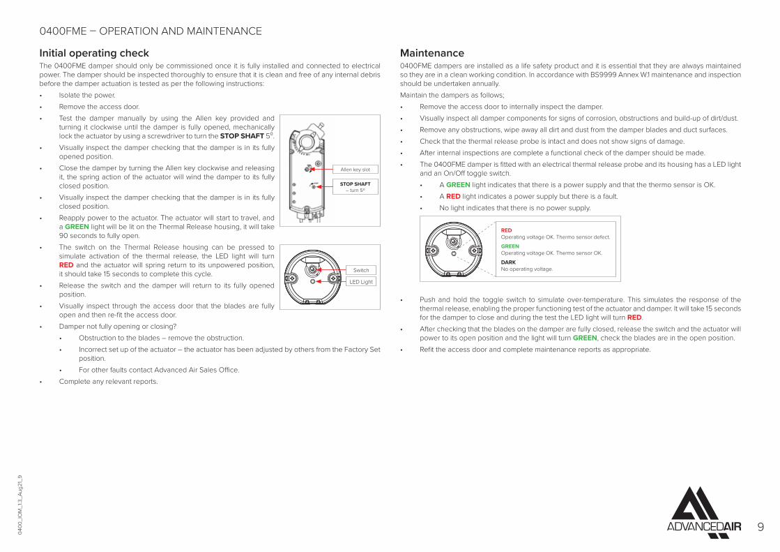
Initial operating checkThe 0400FME damper should only be commissioned once it is fully installed and connected to electrical power. The damper should be inspected thoroughly to ensure that it is clean and free of any internal debris before the damper actuation is tested as per the following instructions:• Isolate the power.• Remove the access door.• Test the damper manually by using the Allen key provided and
turning it clockwise until the damper is fully opened, mechanically lock the actuator by using a screwdriver to turn the STOP SHAFT 5⁰.
• Visually inspect the damper checking that the damper is in its fully opened position.
• Close the damper by turning the Allen key clockwise and releasing it, the spring action of the actuator will wind the damper to its fully closed position.
• Visually inspect the damper checking that the damper is in its fully closed position.
• Reapply power to the actuator. The actuator will start to travel, and a GREEN light will be lit on the Thermal Release housing, it will take 90 seconds to fully open.
• The switch on the Thermal Release housing can be pressed to simulate activation of the thermal release, the LED light will turn RED and the actuator will spring return to its unpowered position, it should take 15 seconds to complete this cycle.
• Release the switch and the damper will return to its fully opened position.
• Visually inspect through the access door that the blades are fully open and then re-fit the access door.
• Damper not fully opening or closing? • Obstruction to the blades – remove the obstruction. • Incorrect set up of the actuator – the actuator has been adjusted by others from the Factory Set
position. • For other faults contact Advanced Air Sales Office.• Complete any relevant reports.
Maintenance0400FME dampers are installed as a life safety product and it is essential that they are always maintained so they are in a clean working condition. In accordance with BS9999 Annex W.1 maintenance and inspection should be undertaken annually.Maintain the dampers as follows;• Remove the access door to internally inspect the damper.• Visually inspect all damper components for signs of corrosion, obstructions and build-up of dirt/dust.• Remove any obstructions, wipe away all dirt and dust from the damper blades and duct surfaces.• Check that the thermal release probe is intact and does not show signs of damage.• After internal inspections are complete a functional check of the damper should be made.• The 0400FME damper is fitted with an electrical thermal release probe and its housing has a LED light
and an On/Off toggle switch. • A GREEN light indicates that there is a power supply and that the thermo sensor is OK. • A RED light indicates a power supply but there is a fault. • No light indicates that there is no power supply.
• Push and hold the toggle switch to simulate over-temperature. This simulates the response of the thermal release, enabling the proper functioning test of the actuator and damper. It will take 15 seconds for the damper to close and during the test the LED light will turn RED.
• After checking that the blades on the damper are fully closed, release the switch and the actuator will power to its open position and the light will turn GREEN, check the blades are in the open position.
• Refit the access door and complete maintenance reports as appropriate.
0400FME – OPERATION AND MAINTENANCE
LED Light
RED Operating voltage OK. Thermo sensor defect.
GREEN Operating voltage OK. Thermo sensor OK.
DARK No operating voltage.
STOP SHAFT – turn 5º
Allen key slot
Switch

0400
_IO
M_1
.3_A
ug21
_10
10
WIRING INSTRUCTIONS – 0400FME1 2 3 4 5 6 7 8
G:\PRODUCTS\DMP - 0400 Series\02 Drawings\D0400 - ES - Electrical Schematics\D0400 ES001 Wiring diagram fire smoke damper actuator\D0400 ES001 rev C Wiring diagram 0400 FME.dwg
Wiring detail for dampers fitted with spring return actuators AA230TS4 or AA24TS4.
0400
_IO
M_1
.3_A
ug21
_11
11
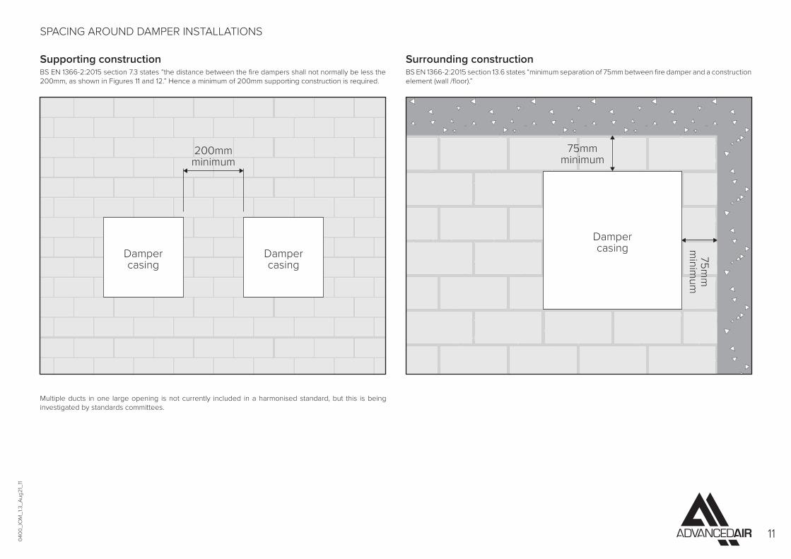
SPACING AROUND DAMPER INSTALLATIONS
Supporting constructionBS EN 1366-2:2015 section 7.3 states “the distance between the fire dampers shall not normally be less the 200mm, as shown in Figures 11 and 12.” Hence a minimum of 200mm supporting construction is required.
Multiple ducts in one large opening is not currently included in a harmonised standard, but this is being investigated by standards committees.
Surrounding constructionBS EN 1366-2:2015 section 13.6 states “minimum separation of 75mm between fire damper and a construction element (wall /floor).”
Dampercasing
200mmminimum
Dampercasing
75mmminimum
75mm
minim
um
Dampercasing

0400
_IO
M_1
.3_A
ug21
_12
12
Fi
re D
ampe
r Cer
tifica
te
CE-
020
CE
Cer
tific
atio
n Re
v 01
Ju
ne 2
019
S M
ann
ing
DW 1
45 In
spec
tion
& H
ando
ver C
heck
She
et to
be
com
plet
ed b
y th
e in
stal
ler w
ith a
sepa
rate
ce
rtifi
cate
for e
ach
dam
per.
No.
Que
stio
n Gu
idel
ines
Ti
ck
1 Ar
e th
e da
mpe
rs th
e co
rrec
t typ
e?
Fire
Dam
per M
odel
016
0, 0
400M
AN
Fire
Dam
per M
odel
255
0, 2
530,
26S
CD
and
0400
FME
2 Ar
e th
e da
mpe
rs co
rrec
tly id
entif
ied?
Id
entif
icatio
n la
bel c
lear
ly sh
ows t
he
dam
per i
ndiv
idua
l ref
eren
ce n
umbe
r
3 Ar
e th
e da
mpe
rs lo
cate
d co
rrec
tly?
The
dam
per p
ositi
on m
atch
es th
e po
sitio
n as
det
aile
d on
the
man
ufac
ture
s ins
talla
tion
inst
ruct
ions
4 Ha
ve su
ppor
ts fo
r bot
h th
e da
mpe
r and
th
e ad
jace
nt d
uctw
ork
been
inst
alle
d in
ac
cord
ance
with
the
appr
oved
met
hod?
5 Ar
e th
e da
mpe
rs fi
tted
in th
e co
rrec
t or
ient
atio
ns?
The
dam
pers
are
inst
alle
d th
e co
rrec
t w
ay u
p re
lativ
e to
airf
low
and
acc
ess
6 Is
acce
ss, t
hrou
gh th
e du
ctw
ork
to th
e da
mpe
r uno
bstr
ucte
d?
Ther
e is
unob
stru
cted
spac
e to
allo
w
safe
acc
ess t
o da
mpe
r, al
so th
roug
h ce
iling
voi
d an
d ad
jace
nt se
rvice
s
7 Co
nfirm
the
spac
e ar
ound
the
dam
per h
as
not b
een
used
for t
he p
assa
ge o
f oth
er
serv
ices
The
pres
ence
of o
ther
serv
ices w
ill
inva
lidat
e th
e in
stal
latio
n m
etho
d
8 Us
ing
the
acce
ss o
peni
ng p
rovi
ded,
co
nfirm
that
the
dam
per h
as b
een
left
in
the
open
pos
ition
9 Re
leas
e th
e da
mpe
r cat
ch to
sim
ulat
e th
e th
erm
al re
leas
e m
echa
nism
(dam
per d
rop
test
)
Ensu
re th
e bl
ade
oper
atio
n is
free
from
in
terfe
renc
e
10
Chec
k da
mpe
r bla
des f
or d
amag
e W
ith th
e da
mpe
r in
the
close
d po
sitio
n in
spec
t for
dam
age
11
Re-s
et d
ampe
r and
repl
ace
acce
ss p
anel
Af
ter r
eset
ting
chec
k th
at if
supp
lied
the
visu
al p
ositi
on in
dica
tor i
s cor
rect
12
Is th
e fir
e ba
rrie
r and
pen
etra
tion
seal
co
mpl
ete?
Conf
irm a
t han
dove
r if i
nsta
llatio
n is
com
plet
e an
d if
no th
en o
ther
trad
es
will
be
requ
ired
to fi
nish
13
Hand
over
dam
per i
nsta
llatio
n fo
r co
mm
issio
ning
Obta
in re
leva
nt a
ccep
tanc
e of
the
dam
per i
nsta
llatio
n fro
m th
e no
min
ated
per
son
resp
onsib
le
Proj
ect
In
stal
ler N
ame
Dam
per I
D No
:
Com
pany
Loca
tion
Da
te
Type
I her
eby
conf
irm th
e da
mpe
r det
aile
d ha
s bee
n in
stal
led
and
test
ed a
ccor
ding
to th
e m
anuf
actu
res r
ecom
men
datio
ns
Mod
el N
o:
Si
gnat
ure


