16

Enter 04810 on infolink at energy-tech.com or see the AD INDEX page 11
Turbine Inlet Cooling Sucess Stories, By Technology
Absorption Cooling ............................................................................ 5
Mechanical Compression Refrigeration............................................ 5
Thermal Energy Storage & Hybrid Chiller Plant.............................. 6
Thermal Energy Storage.................................................................... 6
Turbine Inlet Chilling for Combined-Cycle Plant.............................. 8
Turbine Inlet Chilling for Simple-Cycle Peaker Plant ...................... 8
Evaporative Cooling ........................................................................ 10
Turbine Inlet Cooling for Cogeneration Plant ................................ 14
Advertisers Index . . . . . . . . . . . . . . . . . . . . . . . . . . . . . .11
Buyers Guide: Turbine Inlet Cooling Supply, Installation & Service CompaniesAn alphabetical listing of Turbine Inlet Cooling Supply, Installation & Service providers, suppliers, and related services . . . . . . . . . . . . . . . . . . . . . . . . . . . . . . .12
On the Cover: Exira station, located in the Midwest. Photos courtesy of TAS, Ltd.
In This Issue
14
Devoted to Operations and Maintenance SolutionsDevoted to Operations and Maintenance Solutions
A Publication OfMagellan PublishingA Division of WoodwardCommunications, Inc.
P.O. Box 388 • Dubuque, IA 52004-0388800.977.0474 • Fax: 563.588.3848Email: [email protected]
OFFICE OF THE PUBLISHER
General Manager and PublisherRobin Nichols - [email protected]
OFFICE OF THE EDITOR
EditorJuli Ikonomopoulos - [email protected]
Contributing Editor - [email protected] Punwani
ADVERTISING SALES
Sales ManagerKaren Ruden - [email protected]
Sales ExecutiveJeff Brimeyer - [email protected]
OPERATIONS
Creative Team LeaderCharlotte Thumser - [email protected]
ADDRESS CORRECTIONPostmaster: Send address correction to: Energy-Tech,P.O. Box 388, Dubuque, IA 52004-0388.
SUBSCRIPTION INFORMATIONEnergy-Tech is mailed free to all qualified requesters:Magellan Publishing, Circulation Department, P.O.Box 388, Dubuque, IA 52004-0388 or go towww.energy-tech.com.
MEDIA INFORMATIONFor media kits contact Magellan Publishing at 800.977.0474 or [email protected].
EDITORIALSend press releases to: Editorial Dept., MagellanPublishing, P.O. Box 388, Dubuque, IA 52004-0388Ph 800.977.0474 • Fax 563.588.3848 email: [email protected]
Energy-Tech (ISSN 1062-4147) is published 6 timesyearly by Magellan Publishing, a division ofWoodward Communications, Inc. MagellanPublishing assumes no responsibility for inaccuracies, errors or advertising content. Entirecontents © 2004 Magellan Publishing. All rightsreserved; reproduction in whole or in part withoutpermission is prohibited.
ARTWORKSend Artwork to: Magellan Publishing801 Bluff Street, Dubuque, Iowa 52001
Printed in the U.S.A.
OCTOBER 2004 SUPPLEMENT 3
86
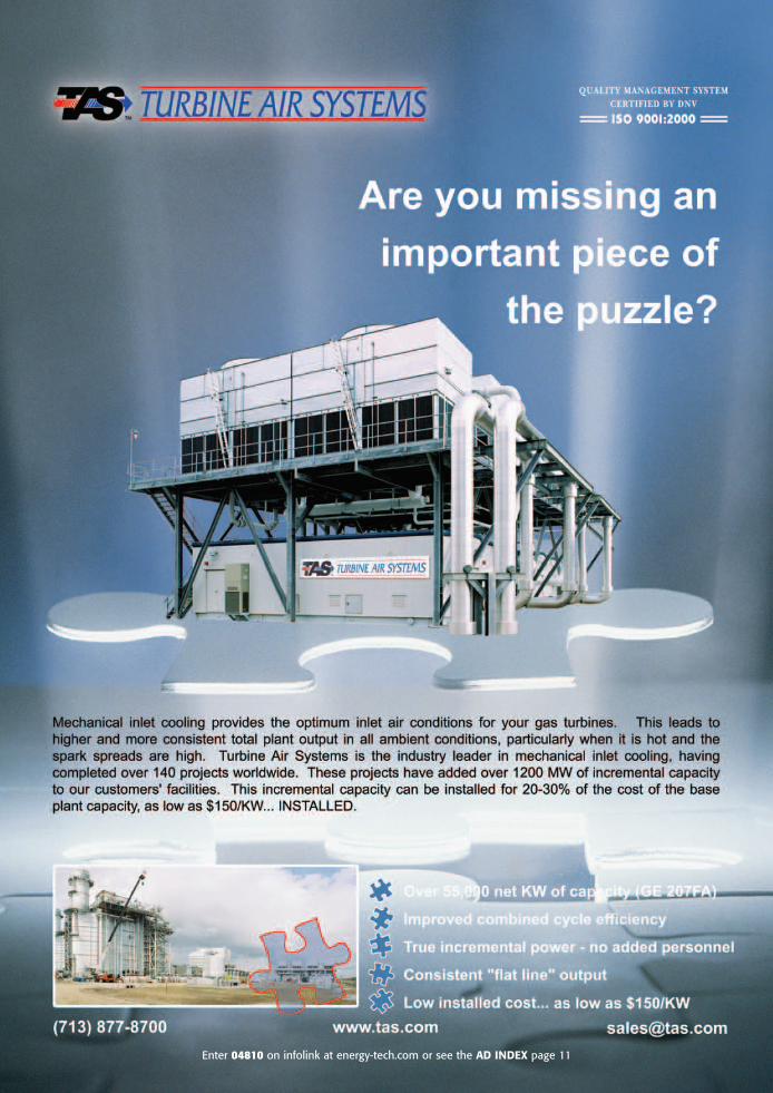
TIC is cooling of the air before it enters the compressor thatsupplies high-pressure air to the combustion chamber fromwhich hot air at high pressure enters the combustion turbine.The primary reason TIC is used is to enhance the power outputof combustion turbines (CTs) when ambient air temperature isabove 59°F.
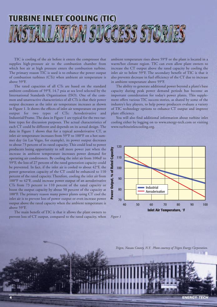
The rated capacities of all CTs are based on the standardambient conditions of 59°F, 14.7 psia at sea level selected by theInternational Standards Organization (ISO). One of the com-mon and unattractive characteristics of all CTs is that their poweroutput decreases as the inlet air temperature increases as shownin Figure 1. It shows the effects of inlet air temperature on poweroutput for two types of CTs: Aeroderivative andIndustrial/Frame. The data in Figure 1 are typical for the two tur-bine types for discussion purposes. The actual characteristics ofeach CT could be different and depends on its actual design. Thedata in Figure 1 shows that for a typical aeroderivative CT, asinlet air temperature increases from 59°F to 100°F on a hot sum-mer day (in Las Vegas, for example), its power output decreasesto about 73 percent of its rated capacity. This could lead to powerproducers losing opportunity to sell more power just when theincrease in ambient temperature increases power demand foroperating air conditioners. By cooling the inlet air from 100oF to59°F, the loss of 27 percent of the rated generation capacity couldbe prevented. In fact, if the inlet air is cooled to about 42°F, thepower generation capacity of the CT could be enhanced to 110percent of the rated capacity. Therefore, cooling the inlet air from100°F to 42°F, could increase power output of an aeroderivativeCTs from 73 percent to 110 percent of the rated capacity orboost the output capacity by about 50 percent of the capacity at100°F. The primary reason many power plants using CT cool theinlet air is to prevent loss of power output or even increase poweroutput above the rated capacity when the ambient temperature isabove 59°F.
The main benefit of TIC is that it allows the plant owners toprevent loss of CT output, compared to the rated capacity, when
ambient temperature rises above 59°F or the plant is located in awarm/hot climate region. TIC can even allow plant owners toincrease the CT output above the rated capacity by cooling theinlet air to below 59°F. The secondary benefit of TIC is that italso prevents decrease in fuel efficiency of the CT due to increasein ambient temperature above 59°F.
The ability to generate additional power beyond a plant’s basecapacity during peak power demand periods has become animportant consideration for today’s power plants. This supple-ment offers various TIC success stories, as shared by some of theindustry’s key players, to help power producers evaluate a varietyof TIC technology options to enhance CT output and improveplant efficiency.
You will also find additional information about turbine inletcooling either by logging on to www.energy-tech.com or visitingwww.turbineinletcooling.org.
4 ENERGY-TECH
IndustrialAeroderivative
Inlet Air Temperature, °F
40
120
110
100
90
80
7050 60 70 80 90 100
Pow
er O
utpu
t, %
of R
ated
Cap
acity
Trigen, Nassau County, N.Y. Photo courtesy of Trigen Energy Corporation.
Figure 1
IntroductionNumerous success stories portray the benefits of TIC installa-
tions. The examples described here serve to illustrate the very broadscope of applications. Specifically, they cover:
▼ Power plant capacities from 1 MW to 750 MW▼ Simple-cycle and combined-cycle applications▼ New construction and retrofit situations▼ Electric utility and independent power/District
Energy/Distributed Generation owners▼ Electric motor-driven, absorption, steam turbine-driven, and
hybrid chiller plants▼ Real-time (or “on-line”) chilling and Thermal Energy Storage
(TES) systems▼ Locales including FL, IL, NY, OK, and the Middle
East/Persian Gulf region▼ Systems operating for more than 10 years and others just
coming on-line
Absorption Cooling
Trigen Energy Corporation
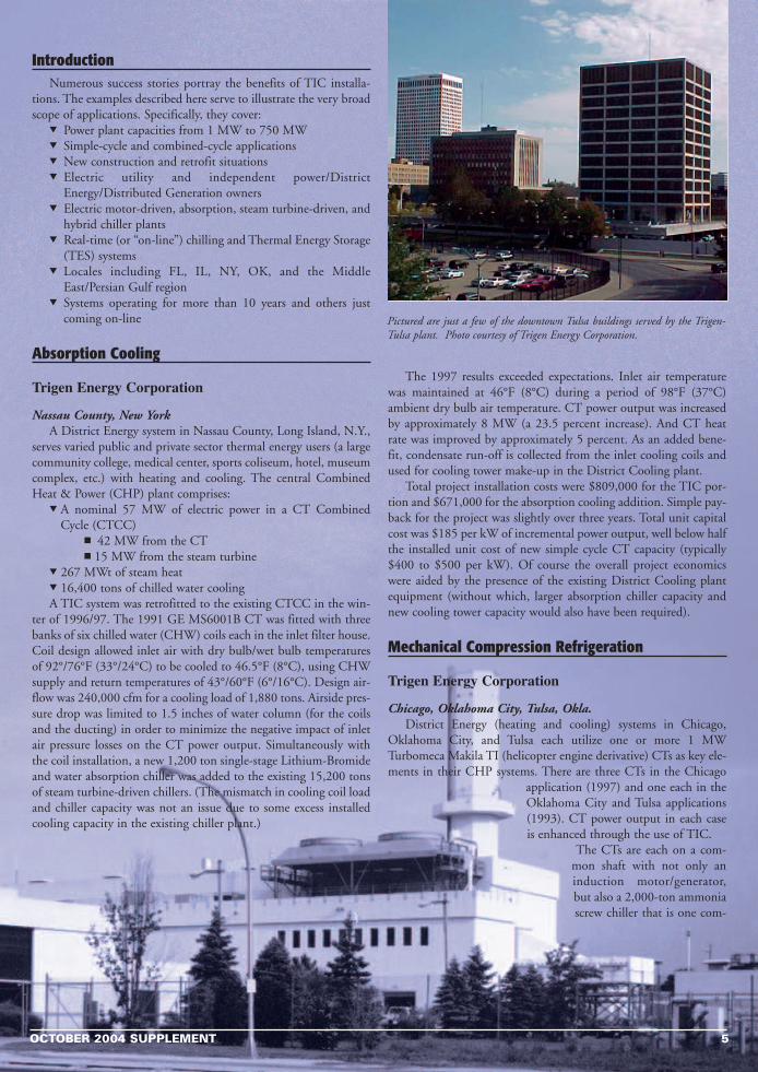
Nassau County, New YorkA District Energy system in Nassau County, Long Island, N.Y.,
serves varied public and private sector thermal energy users (a largecommunity college, medical center, sports coliseum, hotel, museumcomplex, etc.) with heating and cooling. The central CombinedHeat & Power (CHP) plant comprises:
▼ A nominal 57 MW of electric power in a CT CombinedCycle (CTCC)
■ 42 MW from the CT■ 15 MW from the steam turbine
▼ 267 MWt of steam heat▼ 16,400 tons of chilled water coolingA TIC system was retrofitted to the existing CTCC in the win-
ter of 1996/97. The 1991 GE MS6001B CT was fitted with threebanks of six chilled water (CHW) coils each in the inlet filter house.Coil design allowed inlet air with dry bulb/wet bulb temperaturesof 92°/76°F (33°/24°C) to be cooled to 46.5°F (8°C), using CHWsupply and return temperatures of 43°/60°F (6°/16°C). Design air-flow was 240,000 cfm for a cooling load of 1,880 tons. Airside pres-sure drop was limited to 1.5 inches of water column (for the coilsand the ducting) in order to minimize the negative impact of inletair pressure losses on the CT power output. Simultaneously withthe coil installation, a new 1,200 ton single-stage Lithium-Bromideand water absorption chiller was added to the existing 15,200 tonsof steam turbine-driven chillers. (The mismatch in cooling coil loadand chiller capacity was not an issue due to some excess installedcooling capacity in the existing chiller plant.)
The 1997 results exceeded expectations. Inlet air temperaturewas maintained at 46°F (8°C) during a period of 98°F (37°C)ambient dry bulb air temperature. CT power output was increasedby approximately 8 MW (a 23.5 percent increase). And CT heatrate was improved by approximately 5 percent. As an added bene-fit, condensate run-off is collected from the inlet cooling coils andused for cooling tower make-up in the District Cooling plant.
Total project installation costs were $809,000 for the TIC por-tion and $671,000 for the absorption cooling addition. Simple pay-back for the project was slightly over three years. Total unit capitalcost was $185 per kW of incremental power output, well below halfthe installed unit cost of new simple cycle CT capacity (typically$400 to $500 per kW). Of course the overall project economicswere aided by the presence of the existing District Cooling plantequipment (without which, larger absorption chiller capacity andnew cooling tower capacity would also have been required).
Mechanical Compression Refrigeration
Trigen Energy Corporation
Chicago, Oklahoma City, Tulsa, Okla.District Energy (heating and cooling) systems in Chicago,
Oklahoma City, and Tulsa each utilize one or more 1 MWTurbomeca Makila TI (helicopter engine derivative) CTs as key ele-ments in their CHP systems. There are three CTs in the Chicago
application (1997) and one each in theOklahoma City and Tulsa applications(1993). CT power output in each caseis enhanced through the use of TIC.
The CTs are each on a com-mon shaft with not only aninduction motor/generator,but also a 2,000-ton ammoniascrew chiller that is one com-
OCTOBER 2004 SUPPLEMENT 5
Pictured are just a few of the downtown Tulsa buildings served by the Trigen-Tulsa plant. Photo courtesy of Trigen Energy Corporation.
ponent of the larger District Cooling plant. A side stream of ammo-nia refrigerant is evaporated in a coil located in the inlet air streamto the CT, thus providing the desired inlet air cooling and CTpower enhancement.
Using TIC to cool the inlet air to 50°F (10°C) enhances poweroutput by 33 percent or more on the peak design day. In each ofthese three installations, the cooling duty for the TIC system is onlya fraction of one percent of the total District Cooling system capac-ity. Accordingly, it was a simple and economical matter to add theinlet air coil and interconnecting refrigerant lines, with virtually noimpact on the overall cooling system design, thus capturing the CTpower output increase at very low capital cost.
Thermal Energy Storage (TES)& Hybrid Chiller Plant
Walt Disney World/Reedy Creek ImprovementDistrict
Lake Buena Vista, Fla.A District Energy system outside Orlando, Fla., serves the
world-renowned Walt Disney World entertainment complex withheating, cooling, and electric power (Clark, 1998). The centralCHP plant comprises:
▼ A nominal 40 MW of electric power in a CTCC■ 32 MW from the CT■ 8.5 MW from the steam turbine
▼ 90,000 pounds/hour of steam from a HRSG (for HWDistrict Heating and absorption chillers)
▼ 14,425 tons of chilled water cooling (absorption and, prima-rily, electric centrifugal chillers)
A TIC system was retrofitted to the existing CTCC in 1997/98.The existing GE LM5000 CT was fitted with four banks of CHWcoils in the inlet filter house. Coil design allowed inlet air with drybulb/wet bulb temperatures of 95°/79°F (35°/26°C) to be cooled to50°F (10°C), using CHW supply and return temperatures of
40°/70°F (4°/21°C). Design airflow was 219,200 cfm. Air-sidepressure drop was limited to 1.2 inches of water column (across thecoils only) in order to minimize the negative impact of inlet airpressure losses on the CT power output. Simultaneously with thecoil installation, a new 57,000 ton-hour stratified CHW TES tankwas added to the existing 17,750 tons of electric and absorptionchillers. (The addition of the TES capacity was sufficient, not onlyto meet the new load associated with the TIC system, but also toeliminate the need for two new chillers of 3,325 tons capacity thatwould otherwise have been required to replace aging, inefficient,CFC refrigerant chillers that were retired when the TES system wasadded. Even without those two new chillers, excess nighttimechiller plant capacity is adequate to meet nighttime cooling loadsand to charge the TES tank for use the next day in meeting peakloads in both the District Cooling system and in the TIC system.)
CT power output is increased by up to 8 MW (more than a 30percent increase) in extreme weather conditions, from 26 MW at95°F (35°C) to 34 MW at 50°F (10°C). And CT heat rate is alsoimproved by approximately 6 percent.
The 5 million gallon (19 million liter) stratified CHW TESreservoir is an insulated, above ground, welded-steel storage tank,116 feet (35.4 m) in diameter and 67 feet (20.4 m) high. The57,000 ton-hour capacity provides 2,000 tons for TIC and 3,500tons for the District Cooling system, for up to 10 hours per day.Design CHW supply temperature is 40°F (4°C) for both systems,with CHW return temperatures of 70°F (21°C) for the TIC systemand 55°F (13°C) for the District Cooling system.
Although actual project economics are not available for publica-tion, the TIC-TES project achieved the following results:
• Up to an 8 MW (over 30 percent) increase in on-peak CTpower output
• A 12 MW reduction in on-peak power purchases• Elimination of the need for 3,325 tons of new chiller plant
capacity• Operating energy savings providing an attractive rate or return
on the invested capital• A Net Present Value (NPV) for the project totaling several
millions of dollars.
Thermal EnergyStorage (TES)
Utility Power Plant
Middle East/Persian GulfRegion
An existing electric utilitypower plant in the MiddleEast/Persian Gulf region isbeing retrofitted with TIC.The applicable portion of theplant comprises 10 CTs, each anominal 75 MW, in simplecycle configuration. The TICsystem installation is nearlycomplete, with TIC operationsscheduled to commence in2005.
The existing GE Frame7EA CTs are being fitted withcooling coils. Coil design will
6 ENERGY-TECH
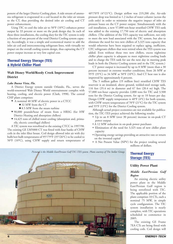
Pictured is the Middle East/Persian Gulf TIC-TES system. Photo courtesy of The Stellar Group.
allow inlet air with a dry bulb temperature of 122°F (50°C) to becooled to 54.5°F (12.5°C). Design cooling load is approximately3,000 tons at each of the 10 CTs. Air-side pressure drop is limitedacross the coils and ducting in order to minimize the negativeimpact of inlet air pressure losses on the CT power output.
A combination chiller plant and TES system have been installedto provide the cooling. The chiller plant employs the packagedplant approach and uses electric motor-driven chillers and, due tothe high value of water resources in the region, air-cooled con-densers for the R-134a refrigerant. The stratified CHW TES reser-voir is an above ground, welded-steel tank, which is charged during18 non-peak hours per day and discharged during the six hours ofpeak power demand per day. The 193,000 ton-hour TES capacityprovides 30,000 tons of cooling for TIC, for six hours per day, min-imizing parasitic power consumption, and maximizing net powerplant output, during the period of peak power value.
Net power plant output is guaranteed to be increased by 30 per-cent in the design day weather conditions. CT heat rate is also sig-nificantly improved.
A very low installed capital cost was achieved, in large partthrough the use of the packaged chiller plant approach, but mostsignificantly by using the TES system to reduce the required capac-ity of the new chiller plant from 30,000 tons to only 11,000 tons.And by using a relatively high supply-to-return temperature differ-ential in the chilled water system, the size and capital cost of theTES tank (and of the CHW pumps and piping) were minimized.The total project capital cost is well below half the installed cost of
equivalent new simple cycle CT capacity (which would haverequired the addition of three more CTs).
References1. Andrepont, J.S., “Combustion Turbine Inlet Air Cooling
(CTIAC): Benefits, Technology Options, and Applicationsfor District Energy,” Proceedings of the IDEA (InternationalDistrict Energy Association) 91st Annual Conference,Montreal, Quebec, June 2000.
2. Clark, K.M. et al., “The Application of Thermal EnergyStorage for District Cooling and Combustion Turbine InletAir Cooling,” Proceedings of the IDEA 89th AnnualConference, San Antonio, Texas, June 1998.
The stories on pages 5-7 were submitted by John S. Andrepont,founder and president of The Cool Solutions Company, Lisle, Ill.John has 30 years of experience in energy technologies, includingvarious turbine inlet cooling projects and over 100 thermal energystorage installations. Cool Solutions provides consulting servicesrelated to TIC, TES, and District Cooling systems. He is the currentchairman and director of the Turbine Inlet Cooling Association(TICA), www.turbineinletcooling.org. You may contact John [email protected]
OCTOBER 2004 SUPPLEMENT 7
For more information enter 04150 on infolink at energy-tech.com or see the AD INDEX page 11
P O W E R G E N E R A T I O N D E S I G N • P O W E R P L A N T D E V E L O P M E N T S U P P O R T • C O N S T R U C T I O N M A N A G E M E N T
Office Locations: Amarillo, TX; Atlanta, GA; Denver, CO; Groton, CT, Minneapolis, MN; Omaha, NE
www.ue-corp.com
Operators of coal-fired power plants look to Utility Engineering
to develop new or expand current facilities. Why? Because
we’ve been in the forefront of clean,
cost-effective design and continue to
lead in developing a new generation of
plants. Customers rely on UE to provide world-class solutions
which maximize customers’ assets, enhance their competitive
position, and contribute to long-term success. It’s important to
team with a partner who can manage all aspects – development,
detailed design, construction supervision, start-up, and training.
To power your future, contact Utility Engineering at
1-800-403-5189 or visit us on the web at www.ue-corp.com.
Your Power Solutions Partner
Coal Powered
TURBINE INLET CHILLINGfor Combined-Cycle Plant
Brazos ValleyTexas
IntroductionTurbine Air Systems (TAS) recently designed and installed two
of their F-50C chiller packages for a 610MW power plant locatednear Richmond, Texas, about 30 miles south of Houston. The com-bined-cycle plant, originally built for NRG by Black & Veatch,E&C contractors, and now operated by Brazos Valley Energy LP,includes two GE Frame 7FA gas turbine-generating sets, HeatRecovery Steam Generation (HRSG), and steam turbine-genera-tors, for a combined output of 631MW. The project was commis-sioned in April 2003 and has completed two summers of successfuloperations.
Project DescriptionThe Brazos Valley Project has two F-50C chiller packages tied
together by an optional “forward” pipe rack. Each F-50C packageis anchored by two Trane CDHF 2500 “Duplex” Chillers andincludes 3 x 50% redundant chilled water and condenser pumps;four cooling tower cells; forward pipe rack manifolds; an electricaldistribution skid allowing a single medium voltage (4160V) feedfrom the customer; two sets of air inlet cooling coils; two sets of coilmanifold piping; and two sets of supply and return riser piping. Theuse of Trane Duplex chillers in series provides for the most efficientchiller system in its class. Each basic chiller plant was delivered inthree self-contained pieces and installed in one week by a crew of six.
Design conditions for the plant specified 93.4ºF dry bulb and76.9ºF wet bulb, and inlet air at 56ºF (13.3ºC) with an alternatedesign point of 52ºF (11.2ºC), which was selected by the cus-tomer. The calculated load for the chilled water system was 9,590tons, and 11,900 tons for the chosen alternate. TAS provided aturnkey installation of the chiller packages and the inlet air coilsfor this project. The installation was completed in less than eightweeks.
Customer Added ValueThe TIC application added over 55 net MW to the facility com-
bined cycle output, while maintaining combined cycle heat rate. Amajor benefit of inlet air chilling for this project is that the opera-tor knows the absolute power output AND the heat rate of theplant every single day, regardless of ambient temperature or powerdemand fluctuations. This provides for accurate bidding of powerinto the merchant market AND reliable forecasting of natural gasusage.
In addition, at Brazos Valley, the operator is using the TIC sys-tem to control total system output, allowing the gas turbines tooperate at base load while handling the variations in output bymodifying the gas turbine inlet air temperature.
SummaryThis is an example of TAS’ flagship model, the F Series system.
Although this package was originally conceived as a “clean-sheet”design to support the F-class fleet of gas turbines, the F-Serieschiller model has become the reference standard for all large-ton-nage applications, proceeding to support aero-derivative projects aswell as District Cooling Applications.
TAS’ scope also included the design, provision, and installationof the cooling coils at the filter house, including a sophisticated self-balancing reverse-return manifold and all local supply piping, withtemperature control valves.
FOR COMPANY INFORMATION,ENTER 04810 ON INFOLINK AT ENERGY-TECH.COM
TURBINE INLET CHILLINGfor Simple-Cycle Peaker Plant
Exira StationMidwest
IntroductionTurbine Air Systems (TAS) recently designed and installed a sin-
gle F-50C packaged chiller system for a 90 MW power plant locat-ed between Des Moines, Iowa and Lincoln, Nebraska. The simple-
cycle peaker plant, built by HarrisGroup, and RW Beck (owner’s engi-neer) for a municipal utility, includestwo GE LM6000PC Sprint gas tur-bine-generating sets. The project wascommissioned in April 2004 and hasbeen successfully operating throughoutthe summer.
Project DescriptionDesign conditions for the plant
specified 95.5ºF dry bulb at a 58.6 per-cent relative humidity. The inlet chill-ing system cools the inlet air to 48ºFfor maximum gas turbine output andefficiency. The capacity of the chilledwater system is 5,100 tons, at designconditions. The TAS’ F-50C package is
8 ENERGY-TECH
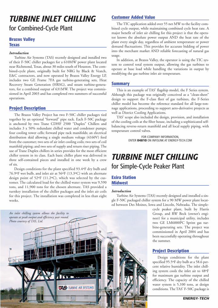
An inlet chilling system allows the facility tooperate at peak output and efficiency year round.Photo courtesy of TAS, Ltd.

anchored by two Trane CDHF 2500 “Duplex”chillers and includes 3 x 50% redundant chilledwater and condenser pumps; four cooling towerscells; dual electrical feeds from the customer; andDelta V controls. To improve off-design efficiency,the system is supplied with variable frequency driveson the chilled water pump and cooling tower fanmotors. Each basic chiller plant was delivered inthree self-contained pieces (chillers, pumps, and elec-trical controls), allowing for shorter constructiontime. TAS provided all materials to the site andincluded technical installation supervision. Theinstallation was completed in approximately fiveweeks.
Customer Added ValueThe TIC application added over 15 net MW to the facility’s
output, while improving the facility heat rate by over two percent.A major benefit, in addition to the 20 percent increase in output,of inlet air chilling for this project is that the utility knows monthsin advance the exact power output and heat rate for the plant,regardless of any day’s temperature or special weather conditions(humid, dry, etc.). This provides for accurate planning of powerproduction as well as better forecasting the municipal utility’s needto purchase power from the market. The ability to know these exactconditions also allows the owner to make better long-term pur-chases of natural gas.
SummaryThis is an example of TAS’ flagship model, the F Series system.
Although this package was originally conceived as a “clean-sheet”design to support the F-class fleet of gas turbines, the F-Serieschiller model has become the reference standard for all large-ton-nage applications, proceeding to support aero-derivative projects aswell as District Cooling Applications.
FOR COMPANY INFORMATION,ENTER 04810 ON INFOLINK AT ENERGY-TECH.COM
OCTOBER 2004 SUPPLEMENT 9
For more information enter 03874 on infolink at energy-tech.com or see the AD INDEX page 11
Exira Station. Photo courtesy of TAS, Ltd.
Evaporative Coolingfor Cogeneration Plant
Hunts Bay Power StationKingston, Jaimaica
Introduction
The Hunts Bay Power Station is a 668-megawatt (MW) com-bined-cycle cogeneration power plant located in Kingston, Jamaica.The plant is owned by Jamaica Public Service Company Ltd.
The Hunts Bay facility includes three combustion turbines: twoGT Browns and one GE Frame 7. They needed to improve plantoperations and increase output and efficiency in order to recoverpower and generate greater revenue. In addition, nitrous oxides andcarbon monoxide emissions must be continuously monitored andcontrolled at the facility with minimal environmental impact.Installation of an evaporative cooling system increased power out-put by 2.4 MW.
Project DescriptionThe average annual growth in demand for electricity in Jamaica
over the past 10 years was approximately 5 percent and the forecastfor the next five years is 6 percent/annum.
“It was expected that by the years 2003 and 2004 the demandwill have surpassed our generating capacity,” said Dave Stamp,Facility Engineer for Hunts Bay Power Station.
A gradual reduction in capacity is expected with increased ambi-ent temperature, hence in Kingston, with high ambient tempera-tures of 90º-92ºF in the summer months, only approximately 85percent of ISO MCR can be realized.
It was with this in mind that Jamaica Public Service CompanyLtd. investigated ways to increase the capacity of its generatingunits. One such method utilizes evaporative cooling technology tocool the inlet air to the gas turbine.
The SolutionIn order to prove the suitability of the inlet air cooling technol-
ogy to the Jamaican climatic conditions, a pilot project was con-ceived. Gas Turbine no. 4, a John Brown Engineering MS5001(Frame 5) unit with an ISO rating of 25.5 MW [59ºF and 14.7pounds per square inch absolute (psia) inlet air] and a site rating of21.750 MW (88°F and 14.7 psia), was selected.
There were several reasons Hunts Bay chose to use an evapora-tive cooling system at the plant versus other cooling methods: easeof retrofit installation, low operating cost, and low inlet pressuredrop.
The pilot test was conducted for six months, from Januarythrough June 2000. The results of the test proved that Hunts BayPower Station benefited from the installation of the evaporativecooling system.
SummaryThe Hunts Bay Power Station regained as much as 10 percent
of the power capacity with the addition of the evaporative coolingunit.
Benefits:
Increased Power Output: The maximum load achieved during thetest was 24.6 MW at 88ºF. This represents an increase of 2.4 MW.
Reduced Pressure Drop: The old inlet filters were removed andreplaced with the evaporative cooler, which resulted in a muchlower pressure drop.
Reduction in Heat: An average reduction in heat rate of 1.6 per-cent with annual savings of $40,857.00.
Low Maintenance: The evaporative cooling system is low inmaintenance.
This success story was submitted by Munters Corporation.
Evaporative Coolingfor Combined-Cycle PlantKalaeloa Cogeneration PlantKalaeloa, Hawaii
Introduction
Kalaeloa Cogeneration Plant is a combined-cycle combustionturbine facility located in Kapolei, Hawaii. As a partnershipbetween ABB Energy Ventures and Kalaeloa Investment Partners,the cogeneration plant provides a portion of the steam needs forTesoro Hawaii Corporation, one of the two oil refineries in the stateof Hawaii, as well as 180 MW of firm capacity net electrical powerto Hawaiian Electric Company.
The combined-cycle plant design includes two ABB 74.6 MWtype 11N gas turbines, one ABB 51.5 MW extraction/condensingsteam turbine, and two Deltak heat recovery steam generators(HRSG), plus a balance of equipment that completes the combinedcycle.
Project DescriptionKalaeloa Partners L.P. decided to examine the plant’s system
design to determine what capital upgrades could be implemented toincrease plant output and efficiency. They found that an evapora-tive cooling system was one such upgrade that could do just that.
The cleaner and cooler the air taken into the turbine, the moreefficiently the turbines operate, resulting in a higher power output.Conversely, as the air inlet temperature rises, power output falls andefficiency decreases.
Kalaeloa Partners knew they could recover lost power by coolingintake air before it enters the gas turbine. That is when Kalaeloacontacted a few evaporative cooling manufacturers, includingMunters Corporation, Systems Division.
After careful analysis, Kalaeloa Partners L.P. decided to retrofitboth of the ABB 11N gas turbines with a stand-alone evaporativecooling system designed and developed to increase output levelsand improve thermal efficiency. This system was chosen over theother types of cooling systems such as fogging and air chillersbecause of simplicity, reliability, and cost. The fogging systems didnot appear to have the track record of producing the reliable cool-ing effect we were looking for, and the air chillers are very costly toinstall and operate.
10 ENERGY-TECH

Kalaeloa projected an approximate 2.1 MW increase oneach combustion turbine, for a total plant output increase of4.2 MW.
SummaryActual power increase has been higher than anticipated –
closer to a 5 MW total increase. In addition, they have experi-enced almost a full MW increase on the steam turbine as wellbecause the heat energy in the exhaust gas increased, thusallowing the HRSG to produce more steam for the combinedcycle to take advantage of.
In evaporative cooling, intake air is passed through one ormore wet pads to simultaneously absorb moisture and cool theair. The cool, humid air is directed to the area where it is need-ed. The installed evaporative cooling system cools the inlet air,creating denser air and giving gas turbines a higher mass flowrate and pressure ratio, thus resulting in an increase in poweroutput and efficiency.
This success story was submitted by Munters Corporation.
OCTOBER 2004 SUPPLEMENT 11
Recapture lost hot-weatherpower output . . .
. . . for a fraction the $/MWof conventional plants!
The Turbine Inlet Cooling Association (TICA) brings togetherparties interested in the benefits of turbine inlet cooling (TIC).The TICA mission is to promote the development andexchange of knowledge related to TIC, for enhancing powergeneration worldwide, and to be the premier one-stop sourceof information on TIC.
TICA membership provides benefits to: power plantowners/operators, plant EPCs, turbine OEMs, TIC system &component suppliers, contractors, consultants, and interestedindividual professionals & associations.
See how TICA can benefit you. Join with some of our current members:
Avalon Consulting ◆ Axford Turbine Consultants ◆ BaltimoreAircoil Company ◆ Chicago Bridge & Iron ◆ Cool SolutionsFES Systems ◆ Kohlenberger Associates ◆ Marley Cooling
Technologies ◆ Munters ◆ South-Port SystemsThe Stellar Group ◆ Strategic Energy Services ◆ Trane ◆ Turbine
Air Systems ◆ Weir Techna ◆ York International
Visit www.turbineinletcooling.orgOR CALL 630-357-3960
(FAX 630-357-1004)
No Cooling Wetted Media Fogging Chillers
Capa
city
Enha
ncem
ent,
MW
No Cooling Chillers Fogging Wetted Media
Incr
emen
tal C
apita
l Cos
t, $/
kW
WANT MORE INFORMATION... About our Products and Advertisers?
Complete this form and FAX it to us at 563.588.3848,MAIL it to us at P.O. Box 388, Dubuque, Iowa 52001,
OR Visit us online at www.energy-tech.comclick infolink and enter the 5 digit number under the
product or customer you want more information about.
I Want More Information About These Customers:❏ Parker Hannifan Gas (04523) . . . . . . . . . . . . . . . . . . . 15❏ The Stellar Group (04858) . . . . . . . . . . . . . . . . . . . . . . 16❏ Testo (03874) . . . . . . . . . . . . . . . . . . . . . . . . . . . . . . . . . . 9❏ Turbine Air Systems (04810) . . . . . . . . . . . . . . . . . . . . . 2❏ Utility Engineering (04150) . . . . . . . . . . . . . . . . . . . . . . 7
Please Send Information To:
Name: ____________________________________________
Company: __________________________________________
Address: __________________________________________
City/State/Zip: ______________________________________
Phone: ____________________________________________
Fax: ______________________________________________
Email: ____________________________________________
AD INDEX

AAF International, Louisville, ILTom Day, Marketing ManagerP | 888.223.3596E | [email protected] cooling systems ductwork, acoustic enclosures,exhaust silencers, anti-icing inlet filtration supportstructures, bleed systems.
Anderson – Snow Corp., Schiller Park, ILMark Beck, SalesP | 847.678.3823E | [email protected] a complete line of heavy duty heatingand cooling coils for new applications or replace-ment.
Atomizing Systems Inc., Ho-Ho-Kus, NJMichael Elkas, PresidentP | 201.447.1222E | [email protected] fog nozzles, lifetime guarantee, andhigh pressure fog pump systems equipped with VFDcontrols.
BETE Fog Nozzle, Inc., Greenfield, MAVictor Urquiola, Chief Sales ExecutiveP | 413.772.2166E | [email protected] is a leading designer and manufacturer ofnozzles for industry, pollution control, and fire pro-tection.
Brentwood Industries, Reading, PADon Zelek, Service ManagerP | 610.236.1100E | [email protected] of turbine inlet drift eliminators andcooling tower film fills produced from non-corrosivePVC.
Caldwell Energy Company, Louisville, KYJohn Kraft, PresidentP | 502.964.6450E | [email protected]
Camfil Farr, Houston, TXGreg Jandjez, Sales ManagerP | 281.861.8488E | [email protected] Farr designs and manufactures complete gasturbine air inlet systems, filtration, cooling, andnoise control.
CAT PUMPS, MINNEAPOLIS, MNDarla Jean ThompsonP | 763.780.5440E | [email protected] low-maintenance high-pressure reciprocating pumps for mist cool-ing, wash down, reverse osmosis, injection,metering.
Colmac Coil Manufacturing, Inc., Colville, WARandy Carstens, P.E., Heat Transfer Products Mgr.P | 800.845.6778E | [email protected] Coil manufactures custom cooling systemsand coils for the combustion turbine inlet coolingmarket.
DONALDSON COMPANY, INC.,MINNEAPOLIS, MNPatty GulsrigP | 800.431.0555E | [email protected] filters, hydraulic filters, filtration systemspare parts, evap coolers, chiller coil systems.
12 TURBINE INLET COOLING BUYERS GUIDE | ENERGY-TECH
Buyers Guide:
TURBINE INLET COOLING SUPPLY, INSTALLATION & SERVICE PROVIDERSThis is an alphabetical listing of Turbine Inlet Cooling Supply, Installation & Service providers, and related services, who responded to Energy-Tech’s request for company and product information.
ECT Inc., Bridgeport, PABruce Tassone, DirectorP | 610.239.5120E | [email protected] manufactures R-MC, Powerbaek gas tur-bine cleaners and fogging, mass augmentationand customized cleaning hardware systems.
ETS Power Group, Stuart, FLMark Dender, Vice PresidentP | 772.781.3883E | [email protected] turbine reverse engineering company producinghot gas path components for all makes of turbines.
FES Systems, York, PATeresa SaubleP | 717.767.6411E | [email protected]
HRT POWER19901 SW FreewaySugarland, TX 77479P | 281.207.1258F | 281.937.0806E | [email protected] | www.hrtpower.comThe PCM™ series of CT PerformanceEnhancement systems are available inenclosed, road transportable, single-lift skidpackages, capable of supplying 200-6,000tons of chilling capacity. All system compo-nents, refrigeration, pumping, controls, andswitchgear are pre-piped, wired, and requireonly power and condenser/chilled water con-nections once on the site.
Mee Industries, Monrovia, CAJohn MeeP | 800.732.5364E | [email protected]
Munters Corporation, Ft. Myers, FLP | 239-936-1555E | [email protected]
Rolls-Royce, Mount Vernon, OHTony Brough Vice President, MarketingP | 740.393.8888E | [email protected] aeroderivative gas turbine-based powergeneration solutions from 4 MW to 58 MW.
THE STELLAR GROUP2900 Hartley RoadJacksonville, FL 32257P | 800.488.2900F | 904.899.9295E | [email protected] | www.thestellargroup.com Stellar is an international firm that providesdesign, engineering, construction, andmechanical services on design/build, generalcontracting, and construction managementprojects. Stellar is recognized as a leaderdeveloping projects for Industrial, Process &Distribution, Institutional, Healthcare,Power & Utility, and Commercial applications.
See Our Ad In This Issue
TURBINE AIR SYSTEMS4300 Dixie DriveHouston, TX 77021P | 713.877.8700F | 713.877.8701E | [email protected] | www.tas.comTAS has a broad range of packaged and sys-tems integration experience in three keymarket areas: commercial & industrial cool-ing (CIC); turbine inlet cooling (TIC); andcooling, heating & power (CHP).
See Our Ad In This Issue
Turbine Inlet Cooling Association, Naperville, ILP | 630.357.3960E | [email protected] mission of the Turbine Inlet CoolingAssociation (TICA) is to promote the developmentand exchange of knowledge related to gas turbineinlet cooling (TIC) for enhancing power generationworldwide.
SEPTEMBER 2004 SUPPLEMENT | TURBINE INLET COOLING BUYERS GUIDE 13
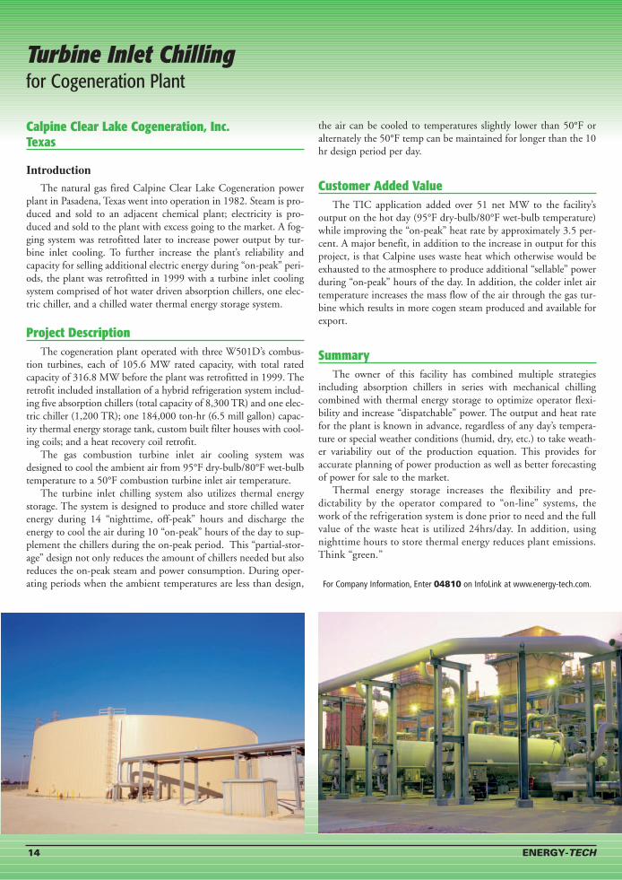
Calpine Clear Lake Cogeneration, Inc. Texas
Introduction
The natural gas fired Calpine Clear Lake Cogeneration powerplant in Pasadena, Texas went into operation in 1982. Steam is pro-duced and sold to an adjacent chemical plant; electricity is pro-duced and sold to the plant with excess going to the market. A fog-ging system was retrofitted later to increase power output by tur-bine inlet cooling. To further increase the plant’s reliability andcapacity for selling additional electric energy during “on-peak” peri-ods, the plant was retrofitted in 1999 with a turbine inlet coolingsystem comprised of hot water driven absorption chillers, one elec-tric chiller, and a chilled water thermal energy storage system.
Project DescriptionThe cogeneration plant operated with three W501D’s combus-
tion turbines, each of 105.6 MW rated capacity, with total ratedcapacity of 316.8 MW before the plant was retrofitted in 1999. Theretrofit included installation of a hybrid refrigeration system includ-ing five absorption chillers (total capacity of 8,300 TR) and one elec-tric chiller (1,200 TR); one 184,000 ton-hr (6.5 mill gallon) capac-ity thermal energy storage tank, custom built filter houses with cool-ing coils; and a heat recovery coil retrofit.
The gas combustion turbine inlet air cooling system wasdesigned to cool the ambient air from 95°F dry-bulb/80°F wet-bulbtemperature to a 50°F combustion turbine inlet air temperature.
The turbine inlet chilling system also utilizes thermal energystorage. The system is designed to produce and store chilled waterenergy during 14 “nighttime, off-peak” hours and discharge theenergy to cool the air during 10 “on-peak” hours of the day to sup-plement the chillers during the on-peak period. This “partial-stor-age” design not only reduces the amount of chillers needed but alsoreduces the on-peak steam and power consumption. During oper-ating periods when the ambient temperatures are less than design,
the air can be cooled to temperatures slightly lower than 50°F oralternately the 50°F temp can be maintained for longer than the 10hr design period per day.
Customer Added ValueThe TIC application added over 51 net MW to the facility’s
output on the hot day (95°F dry-bulb/80°F wet-bulb temperature)while improving the “on-peak” heat rate by approximately 3.5 per-cent. A major benefit, in addition to the increase in output for thisproject, is that Calpine uses waste heat which otherwise would beexhausted to the atmosphere to produce additional “sellable” powerduring “on-peak” hours of the day. In addition, the colder inlet airtemperature increases the mass flow of the air through the gas tur-bine which results in more cogen steam produced and available forexport.
SummaryThe owner of this facility has combined multiple strategies
including absorption chillers in series with mechanical chillingcombined with thermal energy storage to optimize operator flexi-bility and increase “dispatchable” power. The output and heat ratefor the plant is known in advance, regardless of any day’s tempera-ture or special weather conditions (humid, dry, etc.) to take weath-er variability out of the production equation. This provides foraccurate planning of power production as well as better forecastingof power for sale to the market.
Thermal energy storage increases the flexibility and pre-dictability by the operator compared to “on-line” systems, thework of the refrigeration system is done prior to need and the fullvalue of the waste heat is utilized 24hrs/day. In addition, usingnighttime hours to store thermal energy reduces plant emissions.Think “green.”
For Company Information, Enter 04810 on InfoLink at www.energy-tech.com.
14 ENERGY-TECH
Turbine Inlet Chilling for Cogeneration Plant
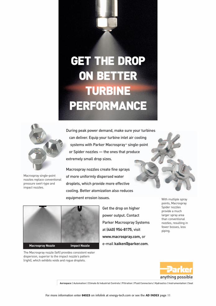
GET THE DROP ON BETTER
TURBINE PERFORMANCE
During peak power demand, make sure your turbines
can deliver. Equip your turbine inlet air cooling
systems with Parker Macrospray™ single-point
or Spider nozzles — the ones that produce
extremely small drop sizes.
Macrospray nozzles create fine sprays
of more uniformly dispersed water
droplets, which provide more effective
cooling. Better atomization also reduces
equipment erosion issues.
Get the drop on higher
power output. Contact
Parker Macrospray Systems
at (440) 954-8175, visit
www.macrospray.com, or
e-mail [email protected].
Macrospray single-pointnozzles replace conventionalpressure swirl-type andimpact nozzles.
With multiple spraypoints, MacrospraySpider nozzles provide a muchlarger spray areathan conventional nozzles, resulting infewer bosses, lesspiping.
Aerospace | Automation | Climate & Industrial Controls | Filtration | Fluid Connectors | Hydraulics | Instrumentation | Seal
The Macrospray nozzle (left) provides consistent waterdispersion, superior to the impact nozzle’s pattern(right), which exhibits voids and rogue droplets.
Macrospray Nozzle Impact Nozzle
For more information enter 04523 on infolink at energy-tech.com or see the AD INDEX page 11

Turbine Inlet Air ChillingA S T E L L A R S O L U T I O N
EXPERT
ANALYSIS
INNOVATIVE
ENGINEERING
MODULAR
FABRICATION
PROFESSIONAL
CONSTRUCTION
QUALITY
INSTALLATION
GUARANTEED
PERFORMANCE
TURNKEY
DELIVERY
OPERATION
& MAINTENANCE
Innovative Power & Utility Project Solutions
2900 Hartley Road • Jacksonville, Florida 32257 • 800-488-2900/904-260-2900 • Fax 904-899-9295Americas • Europe • Middle East • Asia
www.stellarpower.com
For more information enter 04858 on infolink at energy-tech.com or see the AD INDEX page 11


