Building and Asset Services Specification for the construction of «ProjectDescription» at «Address1» «Address2» For Department of Housing and Public Works Site Number: <insert number> Project Number: <insert number> Month, 2013 For all project enquiries during the Tender Period contact: Project Manager: <insert name> Telephone: <insert number> Email: <insert name>@hpw.qld.gov.au For all tender enquiries contact: [email protected]or phone (07) 3224 4398. For all enquiries after the acceptance of tender contact the Superintendent’s Representative. Authorised for Issue: [Name and signature of Principal Consultant] Date: Insert date [dd.mm.yyyy]
Transcript
Building and Asset Services
Specification for the construction of
«ProjectDescription» at
«Address1»
«Address2»
For Department of Housing and Public Works Site Number: <insert number>
Project Number: <insert number> Month, 2013
For all project enquiries during the Tender Period contact:
Project Manager: <insert name>
Telephone: <insert number>
Email: <insert name>@hpw.qld.gov.au
For all tender enquiries contact: [email protected] or phone (07) 3224 4398.
For all enquiries after the acceptance of tender contact the Superintendent’s Representative.
Authorised for Issue: [Name and signature of Principal Consultant]
Date: Insert date [dd.mm.yyyy]
Substantial parts of material in this specification are drawn from NATSPEC BASIC which is a reference specification published by Construction Information Systems Australia Pty Ltd as NATSPEC - the national building specification. This material is developed by Building and Asset Services which is a licensed user of NATSPEC.
BUILDING AND ASSET SERVICES SPECIFICATION FOR APARTMENTS, CLUSTER HOUSING AND ATTACHED HOUSIN G
TABLE OF CONTENTS
Project Number: «ProjectNo »
Address:«Address1» «Address2»
FHP0410 Issue 1/11 v1.0 – Dec 2013 Page 3 of 301
TABLE OF CONTENTS
PART A OF THE SPECIFICATION .......17
010 PRELIMINARIES ...........................19
1 DESCRIPTION OF THE WORKS .................... 19
2 CONTRACTOR’S QUALITY ASSURANCE .... 19
3 QUEENSLAND BUILDING & CONSTRUCTION COMMISSION ACT 1991 ..................... 19
4 WORKS CERTIFIED BY CONTRACTOR’S CERTIFYING CONSULTANTS ............ 19
4.1 WORKS CERTIFIED BY THE CONTRACTOR ....................................... 19
5 APPRENTICE TRAINING ................................ 19
18.1 PROGRESS CLAIM AND PAYMENT BREAKDOWN FOR MULTI UNIT HOUSING (ONE BEDROOM UNITS, APARTMENTS, ATTACHED HOUSES AND CLUSTER HOUSES) AND CONTENT DEFINITION 27
18.2 PROGRESS CLAIM AND PAYMENT BREAKDOWN HOUSES AND DUPLEXES AND CONTENT DEFINITION ................. 28
020 GENERAL REQUIREMENTS ....... 31
1 GENERAL ............................................. ........... 31
35.22 PLAYGROUND UNDER SURFACE TREATMENT ........................................ 291
35.23 SCHEDULE OF PROOF OF ORDERING, APPROVALS, INSPECTIONS, SAMPLES, SOIL DELIVERY, ESTABLISHMENT AND LOG BOOK ........................................... 293
BUILDING AND ASSET SERVICES SPECIFICATION FOR APARTMENTS, CLUSTER HOUSING AND ATTACHED HOUSIN G
PART A OF THE SPECIFICATION
Project Number: «ProjectNo »
Address:«Address1» «Address2»
FHP0410 Issue 1/11 v1.0 – Dec 2013 Page 17 of 301
PART A OF THE SPECIFICATION
BUILDING AND ASSET SERVICES SPECIFICATION FOR APARTMENTS, CLUSTER HOUSING AND ATTACHED HOUSIN G
PART A OF THE SPECIFICATION
Project Number: «ProjectNo »
Address:«Address1» «Address2»
FHP0410 Issue 1/11 v1.0 – Dec 2013 Page 18 of 301
THIS PAGE NOT USED
BUILDING AND ASSET SERVICES SPECIFICATION FOR APARTMENTS, CLUSTER HOUSING AND ATTACHED HOUSIN G
010 PRELIMINARIES
Project Number: «ProjectNo »
Address:«Address1» «Address2»
FHP0410 Issue 1/11 v1.0 – Dec 2013 Page 19 of 301
010 PRELIMINARIES
1 DESCRIPTION OF THE WORKS
Refer to Part B of the Specification Schedule 010 Preliminaries, Particulars of Works and Schedules of Requirements for:
- Scope;
- Location;
- Contract Particulars.
2 CONTRACTOR’S QUALITY ASSURANCE
Refer to Schedule 010 Preliminaries – Contractor’s Quality Assurance.
3 QUEENSLAND BUILDING & CONSTRUCTION COMMISSION ACT 1991
Pay to the Queensland Building & Construction Commission an insurance premium (“the insurance premium”) for the residential construction work, as required under the Queensland Building & Construction Commission Act 1991, unless the work is excluded from being relevant building work under Part 2 of the Queensland Building & Construction Commission Regulation 2003.
Submit to the Superintendent evidence that the insurance premium has been paid.
Furnish evidence of compliance with the requirements of the Queensland Building & Construction Board Rectification of Building Work Policy for residential construction. Arrange for the necessary inspections and certifications required under the policy.
Contractor is responsible to engage a Professional Engineer/s to conduct inspections and provide certification to establish footing construction, including all other structural construction, are built in accordance with Contract Documentation. All costs associated with these requirements (including inspections and certification) will be at the Contractor’s expense.
4 WORKS CERTIFIED BY CONTRACTOR’S CERTIFYING CONSULTANTS
4.1 WORKS CERTIFIED BY THE CONTRACTOR
The Contract is to arrange for independent certifications and where required in the various worksections including Earthworks, Concrete and Structural Steel, etc.
5 APPRENTICE TRAINING
The General Condition of Contract referring to Apprentice Training Requirements shall not apply; where:
- The Contract Sum is $250,000 or less.
- Separate conditions and an apprentice training allowance are agreed or specified elsewhere.
6 CONTRACT DOCUMENTS
6.1 ITEMS The Contract documents comprise all documents described in the Letter of Acceptance of Tender, and include:
- Australian Standard General Conditions of Contract AS 2124-1992. / AS 4305-1996,
- the Special Conditions of Contract including completed Annexure Part A, as issued by the Department of Housing and Public Works and attached to these Tender Documents,
- this Specification, Parts A and B,
- the accepted Tender Form and accompanying Conditions of Tendering,
- the Drawings listed in the Schedule of Drawings,
- any other drawings or documents issued in accordance with the Contract during the course of the Contract.
7 STATUTORY REQUIREMENTS
7.1 PORTABLE LONG SERVICE LEAVE The Principal has undertaken to notify the Building and Construction Industry (Portable Long Service Leave) Authority (“QLeave”) of the building and construction work described in the Contract documents, and to pay all fees required under the provisions of the Building and Construction Industry (Portable Long Service Leave) Act.
7.2 NOTICES TO BE GIVEN AND FEES TO BE PAID
Give notice and pay fees in respect of all statutory requirements, and comply with all relevant statutory requirements in accordance with the Contract Conditions.
Take responsibility as the Principal Contractor under the Work Health and Safety Act.
The Principal will submit to the relevant Local Government copies of plans and specifications and pay appropriate fee.
Apply for water connection and pay all fees (including those for water meters) to the Local Government.
Reimbursement of the fee for the town mains water connection without addition of overheads and profit, will be made to the Contractor on submission of evidence of payment to the Superintendent. The reimbursement of the fee is not applicable to duplex and dual occupancy type projects.
Contractor is responsible for all other costs, including inspection and approval fees, levied by the relevant Local Authority for works necessary to connect to the water supply and to the stormwater and sewerage systems.
BUILDING AND ASSET SERVICES SPECIFICATION FOR APARTMENTS, CLUSTER HOUSING AND ATTACHED HOUSIN G
010 PRELIMINARIES
Project Number: «ProjectNo »
Address:«Address1» «Address2»
FHP0410 Issue 1/11 v1.0 – Dec 2013 Page 20 of 301
Notify the Superintendent when town mains water supply is specified but it is not available at the time of payment for connection fee.
Particular requirements Refer to the Schedules for requirements.
7.3 BUILDING ACT COMPLIANCE DOCUMENTS
In addition to requirements of Clause 8.3 of the General Conditions of Contract, the Principal shall furnish to the Contractor, one set of Building Act compliance documents. Keep these documents on site as required by the Standard Building Regulation. Comply with and complete the detailed requirements of the Building Act compliance documents as a condition precedent to certification of Practical Completion of the Works.
7.4 BUILDING INSPECTIONS Inspections are required in accordance with the requirements of Part 6 of the Building Regulation 2006. The contractor shall be responsible for engaging an independent and suitably competent person to undertake inspections and to issue a compliance certificate. All costs associated with these requirements (including inspection and certification) will be at the contractor's expense. The Contractor will notify the Superintendent of upcoming inspections 2 weeks prior to the inspection or activity occurring. It will be the Contractor's responsibility to liaise with the nominated inspector regarding:
- the type and nature of inspections required,
- the staging and timing of such inspections, and
- notification periods required prior to required inspections.
Fire services Where the building contains "special fire services" (as defined in Schedule 2 of the Building Act), give 48 hours minimum notice to the Superintendent and the Commissioner of Fire Services, so that they can be inspected as required by Section 74 of the Building Act and, if necessary, tested at the following stages:
- after installation and before concealment by subsequent construction work, and
- after installation and before interior finishes are applied.
Mandatory inspections to be provided by Contractor Refer to the General Requirements, Clause 1.10.
7.5 FIRE SERVICES DOCUMENTATION Prior to requesting Practical Completion, prepare and submit the following documents to the officer nominated to perform Building Act Inspections, which are required subject to the provisions of the Building Regulation 2006:
- a list of all “fire safety installations” as defined in Schedule 2 of the Building Act; and
- 3 copies of “as constructed” drawings showing the location of such fire safety installations.
Furnish to the Superintendent 2 copies of the “as constructed” drawings.
Furnish separately to the Superintendent (marked for the attention of the relevant Building Act compliance Officer):
- the list of all “fire safety installations”; and
- 1 copy of the “as constructed” drawings.
Supply all documents collated, bound and parcelled.
8 PRICING
8.1 SCHEDULE OF RATES Reasonably price every item in any Schedule of Rates including:
- labour;
- materials;
- waste of materials;
- custom duties, royalties;
- on site overheads;
- head office costs.
8.2 MEASUREMENT IN BILLS OF QUANTITIES
The Bills of Quantities has been measured in accordance with the Australian Standard Method of Measurement of Building Works (Fifth Edition - January, 1990) (ASMM) published by the Australian Institute of Quantity Surveyors and the Master Builders’ - Construction and Housing Association Australia, Inc., except where stipulated otherwise.
Departure from the Method of Measurement shall not form the basis of any claims for additional payment caused by any such departure.
The quantities have been measured in accordance with the Specification and from the Drawings listed in the Specification.
The Bills of Quantities shall not be used for ordering materials or for manufacture of units.
The item quantities are measured net, fixed in position unless otherwise stated and prices are to include provision for all labour, material, plant, overheads, profit, tools, laps and all waste, cutting, setting out, supervision, nails, screws, spikes, plugs, glue, putty, solder, hauling, hoisting, framing, fitting, and fixing complete.
Every item in the Bills of Quantities shall be reasonably priced and not grouped together as total prices for any trade or section. Unpriced items will be deemed to have their cost included elsewhere or be of nil value.
When extended by the Contractor the prices shall, on addition, equal the Contract Sum.
BUILDING AND ASSET SERVICES SPECIFICATION FOR APARTMENTS, CLUSTER HOUSING AND ATTACHED HOUSIN G
010 PRELIMINARIES
Project Number: «ProjectNo »
Address:«Address1» «Address2»
FHP0410 Issue 1/11 v1.0 – Dec 2013 Page 21 of 301
The Contractor shall include in the price rates and prices generally in the Bills of Quantities for the work described therein complete in place as specified and/or shown on the Drawings.
Dimensions stated in descriptions are, unless stated to the contrary, given in the order length, width and height (or depth).
Division of the Bills of Quantities or SPECIFICATION into trades shall not obligate the Principal to establish the limit of any sub-contract, between the Contractor and the Subcontractor, nor shall the Principal be held responsible for any omission caused by the Contractor in sub-contracting work.
Requirement Refer to the SCHEDULES to the Preliminaries.
9 PROVISIONAL ITEMS
9.1 GENERAL Requirements Refer to the Schedule of Provisional Allowances in the Schedules to ‘Preliminaries’.
9.2 PROVISIONAL SUMS Definition The term "provisional sums" includes prime cost sums and other monetary provisions.
Any PRIME Cost (PC) Sums listed in the SCHEDULE OF PROVISIONAL ALLOWANCES or the Bills of Quantities are deemed to be included in the Contract Sum together with the Contractor’s allowance for margin, coordination and attendance (including any special attendance).
Provisional quantities Where Provisional Quantities of work are given in the Contract Documents, the work shall be re-measured as executed to the satisfaction of the Superintendent and paid for at the unit rates contained in the priced Schedule of Rates or Bills of Quantities, as applicable. The Contractor shall be deemed to have allowed in its offer for all costs incurred in remeasuring, pricing and negotiating the value of work executed.
Items marked PROVISIONAL are subject to re-measurement or complete omission in accordance with instructions given by the Principal.
10 HEALTH AND SAFETY
10.1 OCCUPATIONAL HEALTH AND SAFETY (OHS) AUDITOR
Functions Further to Special Conditions of Contract Clause 15.2.3, the functions which the OHS Auditor shall perform include:
- (a) Part 3.2 of the document, “Managing Occupational Health and Safety on Government Building Projects: Contractor PQC”, available from the PQC Registrar, Department of Housing and Public Works;
- (b) Parts 3.4, 4.0 and 5.0 of the document, “Managing Occupational Health and Safety on Government Building Projects: Guidelines for PQC Auditors” (reference V1-12/2003), produced by Work Health and Safety Queensland, Department of Industrial Relations;
- (c) When submitting to the Superintendent the summary report prepared after completing a Site Inspection pursuant to (a) above, the OHS Auditor shall recommend whether or not:
. work should be suspended for safety reasons;
. urgent action is needed to protect the work under the Contract, other property, or people.
- (d) Pursuant to Part 5.0 of the document mentioned in (b) above, verify that Corrective Action Notices are finalised, and notify the Superintendent when they have all been finalised. If, in the OHS Auditor’s opinion, any are taking too long to finalise then notify the Superintendent of this opinion, and make recommendations as required by (c) above.
Number of Site Inspections required: Project duration 16-25 weeks: One; Project duration 26-38 weeks: Two; Project duration 39 weeks and above: Two, plus one for each additional 13 weeks.
The Contractor shall ensure that all of the above requirements are included in their contract agreement with the OHS Auditor.
Payment Further to Special Conditions of Contract Clause 15.2.4, the Principal shall reimburse the Contractor for the OHS Auditor’s fees incurred in performing the functions specified above, provided always that fees shall not be reimbursed for “failed inspections”. A “failed inspection” shall be as defined in the document, “Managing Occupational Health and Safety on Government Building Projects: Contractor PQC”.
The Contractor shall not be allowed any additional amount for profit, overheads, or attendance in respect of the OHS Auditor’s fees.
The reimbursement procedures shall be as follows:
- After paying the OHS Auditor, the Contractor shall submit a monthly invoice seeking reimbursement to the Superintendent, together with evidence of the amount paid to the OHS Auditor, and a statement of the functions performed in respect of that invoice;
- Invoices for reimbursement of OHS Auditor’s fees shall not be included in payment claims made in accordance with Special Conditions of Contract Clause 42, but may be submitted at any time in the month;
- The invoice shall be addressed to Building and Asset Services, shall include reference to the
BUILDING AND ASSET SERVICES SPECIFICATION FOR APARTMENTS, CLUSTER HOUSING AND ATTACHED HOUSIN G
010 PRELIMINARIES
Project Number: «ProjectNo »
Address:«Address1» «Address2»
FHP0410 Issue 1/11 v1.0 – Dec 2013 Page 22 of 301
Building and Asset Services Project Number, and shall include an allowance for GST;
- The invoice will be considered separately from, and shall be paid separately from, payment claims made in accordance with Special Conditions of Contract Clause 42.
10.2 ACCIDENT REPORTS Promptly notify the occurrence, and furnish a written report, of the following:
- accidents involving death or personal injury;
- accidents involving loss of time;
- incidents with accident potential such as equipment failure, slides, cave-ins, and the like.
10.3 OCCUPIED PREMISES Liaise with tenant in occupied premises to minimise inconvenience.
Refer to the Occupied Premises Schedule:
- permit occupants to continue in secure possession and occupancy of the premises;
- provide safe access for occupants;
- arrange work in occupied or partially occupied premises to minimize nuisance to the occupants and ensure their safety; and
- protect occupancy against weather, dust, dirt, water or other nuisance, by such means as temporary screens, dust barriers etc.
Submit details of proposed methods to meet these requirements.
10.4 NO SMOKING POLICY Smoking in dwelling units is prohibited whether occupied or otherwise. Do not leave butts or other debris on the site at any time.
10.5 CARE OF THE WORKS AND REINSTATEMENT OF DAMAGE AND DAMAGE TO PERSONS AND PROPERTY OTHER THAN THE WORKS
Damage to Services and Property: Do not interfere with or damage services and property which is to remain on or adjacent to the site, including trees and adjoining property encroaching onto the site. Do not obstruct or damage roadways and footpaths on or adjacent to the site. Rectify immediately any interference or damage to such property and provide temporary services whilst repairs are carried out.
Existing services Attend to existing services as follows:
- If the service is to be continued: repair, divert or relocate as required. If such a service crosses the line of a required trench, or will lose support when the trench is excavated, provide permanent support for the existing service.
- If the service is to be abandoned, cut and seal or disconnect, and make safe.
Notification Notify the Superintendent immediately upon the discovery of services or constructions not shown on the Drawings.
Proposals Submit proposals for action to be taken with respect to existing services before starting this work. Minimise the number and duration of interruptions.
Occupied premises Liaise with tenant to minimize inconvenience from disruption.
Cost The Contract shall be deemed to include the cost of dealing as above with existing services:
- the existence of which was ascertainable at the time of tender from the appropriate authority, or from visual inspection on or adjacent to the site; or
- which are shown on the Drawings or described in the Specification; or
- which the Contract states to be the responsibility of the Contractor, regardless of the circumstances of their discovery.
Adjoining property Where adjacent property will be affected by the works, and as agreed with the superintendent, arrange a joint inspection with the superintendent and owners and occupants of the properties, prior to and on completion of the works.
Make detailed records of conditions existing within the properties.
Arrange for 2 copies the records, including drawings, written descriptions, and photographs, to be endorsed by the owners and occupants.
Submit one endorsed copy of the record. Keep the other endorsed copy on site.
Reinstatement Clean and repair damage caused by installation or use of temporary work and restore existing facilities used during construction to original condition unless instructed otherwise.
11 ADMINISTRATION
11.1 SITE MEETINGS Requirement During Construction, arrange meetings fortnightly or as agreed with the Superintendent.
Keep minutes and give a copy to the Superintendent within three working days after each meeting.
Contacts Submit to the Superintendent the names and telephone numbers of all responsible persons who may be contacted after hours
BUILDING AND ASSET SERVICES SPECIFICATION FOR APARTMENTS, CLUSTER HOUSING AND ATTACHED HOUSIN G
010 PRELIMINARIES
Project Number: «ProjectNo »
Address:«Address1» «Address2»
FHP0410 Issue 1/11 v1.0 – Dec 2013 Page 23 of 301
Agenda The Superintendent shall provide the agenda for the first site meeting.
11.2 PROGRAM OF WORK Construction program: Supply a construction program in accordance with the following.
Linked bar chart Within 14 calendar days after notification of acceptance of the tender, submit a detailed linked bar chart having dependency lines showing the intended progress and relationship of one activity upon each subsequent activity set against time scale. The beginning and end of each activity shall be linked with a dependency line and critical path identified. Provision shall be made for entering actual progress. If the Superintendent considers that this bar chart is not sufficient for his purposes or otherwise not satisfactory, he may require the Contractor to provide an amended bar chart within 7 days of being requested to do so.
Revisions: If at any time during the carrying out of the work the progress for any item of work shown on the bar chart is less than that forecast by the bar chart or the Superintendent considers that the bar chart does not show a satisfactory program of work, he may request the Contractor to provide within a stated period, a bar chart showing a revised work plan.
Payment: The Superintendent may refuse payment upon any certificate until such bar charts have been provided.
11.3 PROGRESS SCHEDULE Prepare and submit to the Superintendent, a monthly progress schedule which sets out:
- the true position reached on the Works;
- any deviations from the approved Construction Program;
- circumstances adversely affecting performance of the Works;
- a report on the weather for the past month.
11.4 PROGRESS PHOTOGRAPHS Keep an annotated and dated photographic record to show the prior conditions of the site and progress of the work and submit to the Superintendent on request.
11.5 VARIATIONS Determination of prices for Variations The Contractor is deemed to have allowed in its Tender for all costs incurred in measuring and/or pricing and negotiating the value of variations, and in administering the processing and implementation of variations.
In determining the value of a variation, allowance for profit, off-site overheads and preliminary items shall be included in the agreed rates.
The price for a variation shall not include an allowance for on site overheads unless additional costs associated with such on site overheads are specifically incurred on a particular variation.
12 SITE MANAGEMENT
12.1 SETTING OUT Certification Provide certification from a licensed surveyor that the Works are within the site boundary and the relevant set backs. This shall include a drawing certifying the set-out.
Hand the certificate over to the Superintendent within ten (10) days of the completion of setting out.
Ensure that the whole of the Works will be contained within the setbacks of the boundaries of the site as defined in the Drawings. Be liable for and indemnify the Principal against any liability, loss, claims or proceedings in respect of any encroachments by the Works on adjoining properties.
12.2 CONTRACTOR'S SITE AREAS Restrictions: The Contractor's access to and use of the site shall be restricted to those areas shown on the Drawings or approved by the Superintendent, and subject to such conditions as are stated in the Contract or may be imposed by the Principal.
12.3 GUTTER CROSSING Provide crossing Arrange with the local authority for the provision of a gutter and footpath crossing of the size shown on the Drawings, and pay all fees in connection with this work.
Remove crossing Arrange with the local authority for the removal of the existing gutter and footpath crossing where shown on the Drawings and its replacement with a kerb, gutter and footpath to match similar adjacent existing work, and pay all fees in connection with this work.
12.4 TEMPORARY FOOTPATH CLOSURE Approval: Seek approval from Local Government for the temporary partial or total closing of footpaths.
13 ENVIRONMENTAL CONTROL
13.1 PUBLIC PROPERTY Do NOT place sheds, materials, vehicles, spoil or debris on roads, footpaths, or any other public land without the relevant Authority’s consent.
13.2 TRUCKING Convey soils, earth, sand, loose debris, and the like loose materials to or from the site in a manner that will prevent dropping of materials on streets. Ensure that the wheels, tracks and body surfaces of all vehicles and plant leaving the site are free of mud and that mud is not carried on to adjacent paved streets or other areas.
BUILDING AND ASSET SERVICES SPECIFICATION FOR APARTMENTS, CLUSTER HOUSING AND ATTACHED HOUSIN G
010 PRELIMINARIES
Project Number: «ProjectNo »
Address:«Address1» «Address2»
FHP0410 Issue 1/11 v1.0 – Dec 2013 Page 24 of 301
14 INSTALLED EQUIPMENT
14.1 PROTECTION Protect installed equipment against damage by dust, dirt, shock or other cause.
15 TEMPORARY FACILITIES PLANT AND EQUIPMENT
15.1 TEMPORARY SERVICES Extent Provide and maintain the temporary services necessary for the performance of the contract, and on completion disconnect and clear away all traces.
15.2 SITE OFFICE Provide accommodation for the purposes of the on site administration of this contract including use by the Superintendent and his representatives, holding of site meetings etc.
Remove from site on completion. The office remains the property of the Contractor.
Requirement A site office is not a requirement of this contract.
15.3 PROTECTIVE CLOTHING Requirement Arrange for safety helmets, protective clothing and boots to be available for temporary use of visitors.
15.4 SIGNBOARDS Provide signboard to comply with Queensland Building Services Act. Sign board area of 0.5 square metre painted white professionally lettered in black letters 50 mm high, containing the Builder's Licence Number, Supervisor's Name and Number and other information required by the Act, prominently displayed.
No other signs are permitted without the approval of the Superintendent’s Representative.
15.5 TEMPORARY FENCING Where the works include the taking down, re-erection, or maintenance of existing fencing, the Contractor shall at all times first erect temporary fencing to secure the site.
16 COMPLETION
16.1 CONTRACTOR'S OWN DEFECTS INSPECTION
Prior to Practical Completion, undertake a "defects" inspection, and complete making good of such defects prior to offering the Works as practically complete.
Submit evidence that such an inspection of the Works has been carried out and a defects list prepared, the defects remedied, reinspected and are satisfactory.
Ensure all work is complete in accordance with the handover checklist provided by the SR and submit 3
signed copies of the completed checklist at practical completion.
Failure to comply may result in refusal by the Superintendent’s Representative to conduct a Practical Completion inspection until such submission is made.
16.2 RECTIFICATION OF DEFECTS PRIOR TO PRACTICAL COMPLETION
Access to the premises will be greatly restricted after handover at Practical Completion. All listed and otherwise recognised defects are required to be completed before handover is accepted.
16.3 PRACTICAL COMPLETION DOCUMENTS AND PROCEDURES
Before application is made for Practical Completion, thoroughly check out all installations, equipment, and services to ensure that performance is correct and in order.
Obtain from all Authorities written and signed approval for all installations under their control stating their testing and approval of same.
When the Contractor’s Temporary Services Supply (Electrical/Telephone/Gas/Water Supply) is terminated, the Contractor is to hand to the Superintendent copies of the Contractor’s name and Application for Termination of Temporary Services Supply.
Submit to the Superintendent, not later than one week prior to Handover, with the Contractor’s application for a certificate of Practical Completion, the following documents and certificates:
- Certificates of approval for all water supply and drainage works.
- Certificates of approval for the electrical services installation.
- Copies of the Certificates required under the Building Services Board policy on Subsidence.
- Certificates for Critical Radiant Flux index for resilient floor and/or carpet coverings.
- Copies of the Contractor’s Application for Termination of Temporary Services Supply.
- Any other certificate or document so required by the contract but not yet given.
Submit to the Superintendent at Handover, the following documents and certificates:
- Maintenance Manuals.
- Instruction Manuals.
- Warranties.
- Guarantees.
- Any other certificate or document so required by the contract but not yet given.
BUILDING AND ASSET SERVICES SPECIFICATION FOR APARTMENTS, CLUSTER HOUSING AND ATTACHED HOUSIN G
010 PRELIMINARIES
Project Number: «ProjectNo »
Address:«Address1» «Address2»
FHP0410 Issue 1/11 v1.0 – Dec 2013 Page 25 of 301
16.4 AS CONSTRUCTED DRAWINGS Submit at Practical Completion, as-constructed drawings to a size and standard commensurate to that of the contract drawings.
Record accurately to scale and on the same drawing.
- the sewerage, drainage, water supply, irrigation, electrical, gas and telephone services, showing depth of services and dimensions from boundaries, buildings and other obstructions.
Include on the drawings:
- a legend;
- the Project No;
- the Job No;
- the real property description; and
- the address of the Works.
17 MATERIALS AND WORKMANSHIP
17.1 MATERIAL AND WORKMANSHIP Unless otherwise specified, materials shall conform to the Standards and Codes issued by the Standards Association of Australia.
17.2 AUSTRALIAN AND OTHER STANDARDS Current editions An Australian or other standard applicable to the Works should be the current Edition but may be the edition last published not later than one month prior to the closing date for tenders.
Site copies Where reference to a standard is required to resolve differences in respect of compliance with the Contract requirements, provide a copy of the relevant Standard.
17.3 SAMPLES Approved samples Where samples are called for, items supplied are to be in accordance with the approved samples, or an approved alternative within a range defined by approved samples. Keep approved samples in good condition on site until Practical Completion. Where not so specified herein, provide samples upon reasonable request from the Superintendent at no additional cost to the contract.
Delay The Contractor shall be solely responsible for the consequences of delay resulting from failure to allow adequate time for the assessment and approval of samples, or from the rejection of samples which do not comply with the Specification.
17.4 WARRANTIES Name the Principal Warranties or guarantees specified shall name the Principal as warrantee.
Written warranties are required:
- where called for by the Contract Documents;
- on all Appliances and Equipment; and
- where offered by the manufacturers.
All warranty periods shall commence from the Date of Practical Completion and remain in force for the periods specified or if not specified, for a period of twelve (12) months.
17.5 ALTERNATIVE MATERIALS OR WORK The Contractor shall be deemed to have allowed for the materials and methods of work described in the Contract whether they are proprietary items or otherwise.
Where materials specified are not available or the method of work specified is not possible or for any other reason, the Contractor wishes to substitute an alternative material or method of work, then in each instance:
- the Contractor shall request the substitution, from the Superintendent, in writing in time to allow a response to be given within 10 days of receipt of the notice so as not to cause delay to the progress of the Works;
- the Superintendent may allow the substitution at no additional cost to the Principal or the Superintendent may issue a Variation to effect a reduction or increase in the value of the Works; and
- the Contractor shall be responsible for the suitability and performance and the fitness for purpose of the substituted material/item or method of work. The Contractor is required to supply a sample of the proposed item, and evidence that the performance is equal to or greater than that specified.
Claims The Contractor shall not be entitled to compensation for any rejection of a submitted alternative, nor, unless otherwise agreed, shall adoption of an alternative be ground for any claim for additional cost damages or extension of time.
17.6 ITEMS SUPPLIED BY PRINCIPAL Supply Where materials and other items are specified to be supplied free of charge by the Principal to the Contractor for use in the execution of the Works, take delivery of the materials under the specified conditions and fix in accordance with the contract. Refer also ‘RATES AND PRICES’ herein.
17.7 JOINING UP Generally Carry out the joining of new work to existing work, and any consequent cutting away, in a manner appropriate to the materials, and make good to existing work as directed by the Superintendent.
BUILDING AND ASSET SERVICES SPECIFICATION FOR APARTMENTS, CLUSTER HOUSING AND ATTACHED HOUSIN G
010 PRELIMINARIES
Project Number: «ProjectNo »
Address:«Address1» «Address2»
FHP0410 Issue 1/11 v1.0 – Dec 2013 Page 26 of 301
17.8 FIRE ANT RISK MANAGEMENT PLAN Comply with the Plant Protection Regulation 1990 as amended, any relevant Quarantine Notice issued under the Plant Protection Act, and the requirements of this Clause.
Inspect the Site of the Works with appropriately skilled officers of the Department of Primary Industries as soon as possible after being given possession of any part of the Site, noting indications of Fire Ant infestation. Clearly identify, and protect until otherwise directed, the location of any possible Fire Ant infestation.
Prepare a Fire Ant Risk Management Plan, in consultation with appropriate officers of the Department of Primary Industries, which includes as a minimum, the practices listed below. The Fire Ant Risk Management Plan shall be submitted to the Department of Primary Industries for their approval, immediately after preparing the Plan.
Provide a copy of the Fire Ant Risk Management Plan, and a copy of the Approval given by the Department of Primary Industries, to the Superintendent within 14 days of the date of the Letter of Acceptance.
Implement, and maintain the approved Fire Ant Risk Management Plan for the duration of the Contract (including the Defects Liability Period, and the Planting Establishment Period).
The Fire Ant Risk Management Plan shall include, but is not limited to, the following practices:
- training of site supervisors and construction staff in issues related to awareness, detection, reporting and management of Fire Ant infestation;
- regular inspection for indications of Fire Ant infestation of the Site, all excavated, stored, and waste materials, all items placed in contact with the ground, vehicles, machinery, equipment and apparatus of any kind;
- obtaining “high-risk materials” to be incorporated into the Works from suppliers with an appropriate quality assurance system which provides for the management of Fire Ant infestation. “High-risk materials” include sands, gravels, aggregates, soils, imported fill, soil mixes, mulches, plants, hay, straw, grass, seeds, turf, logs, sleepers, pavers, and other materials capable of harbouring Fire Ants;
- maintaining records of the sources of “high-risk materials”;
- obtaining written warranties from suppliers stating that all “high-risk materials” are free from Fire Ant infestation at the time of supply;
- transporting, storing and handling materials to be incorporated into the Works, and waste materials, by methods that minimize the risk of Fire Ant infestation;
- inspection and cleaning of items placed in contact with the ground, vehicles, machinery, equipment and apparatus of any kind, prior to bringing to the Site, and before leaving the Site;
- disposing of surplus “high-risk materials” by placing them elsewhere on the property, or (subject to obtaining all necessary approvals) disposing of “high-risk materials” at a facility approved by the Department of Primary Industries; and
- maintaining records of staff training, inspections, treatments and all other actions undertaken to control the risk of Fire Ant infestation.
Report immediately to the Superintendent any infestation of Fire Ants found on the Site.
Incorporate warranties received from suppliers of “high-risk materials” into the Manuals specified in GENERAL REQUIREMENTS - OPERATION AND MAINTENANCE MANUALS.
For Projects Outside the South-east Queensland Restricted Zones:
Comply with the requirements of the Plant Protection Act, and the Plant Protection Regulation 1990 as amended, and any relevant Quarantine Notice issued under the Plant Protection Act.
Notify the Superintendent seven (7) days prior to their arrival, of the intention to bring onto the site “high-risk” materials or appliances (including vehicles, machinery, equipment or apparatus of any kind), originating in or passing through any Restricted Area declared under the Plant Protection Regulation 1990 as amended.
High-risk materials include imported fill, sands, gravels, aggregates, soils, soil mixes, mulches, plants, hay, straw, grass, seeds, turf, logs, sleepers and other materials capable of harbouring Fire Ants.
Provide a copy of the written approval of an appropriate Inspector from the Department of Primary Industries, or a copy of the Approved Risk Management Plan, which allows movement of the “high-risk” materials or appliances originating in a declared Restricted Area, prior to any such “high-risk” materials or appliances arriving on site.
Provide a written warranty that “high-risk” materials or appliances that have passed through a declared Restricted Area are free from Fire Ant infestation at the time they arrive on site.
Incorporate warranties and approvals into the Manuals specified in GENERAL REQUIREMENTS – Operation and Maintenance Manuals.
BUILDING AND ASSET SERVICES SPECIFICATION FOR APARTMENTS, CLUSTER HOUSING AND ATTACHED HOUSIN G
010 PRELIMINARIES
Project Number: «ProjectNo »
Address:«Address1» «Address2»
FHP0410 Issue 1/11 v1.0 – Dec 2013 Page 27 of 301
18 PROGRESS PAYMENTS
Refer “Conditions of Contract” Clause No 42.1 – Payment Claims (as amended).
18.1 PROGRESS CLAIM AND PAYMENT BREAKDOWN FOR MULTI UNIT HOUSING (O NE BEDROOM UNITS, APARTMENTS, ATTACHED HOUSES AND CLUSTER HOUSES) AND CONTENT DEFINITION
Submit itemised progress claims to through the Superintendent’s Representative for approval.
Generally the following breakdown provides an alternative format for the basis of progress claims.
Where a progress claim is not received by the Superintendent, the following may be used by the Superintendent as the basis for payment to the Contractor.
Note : The schedule "Multi Unit Housing" states the percentages of the Contract Sum for the several items of operations, which together comprise the Works, tabulated for assessing the value of progress payment claims.
The percentages shown against items are average for the groups of accommodation units in the contract and do not necessarily represent the value of any items or of any particular accommodation unit.
1. SITE ESTABLISHMENT: Costs incurred in preparing the site to commence building construction.
2. FILLING AND EXCAVATION: Costs of site clearing, trimming, cut and filling, excavation, imported filling, planking and strutting and termite treatment are included.
Costs of trench excavation for drainage, water, electrical, retaining walls etc. are included with the relevant trade.
BUILDING AND ASSET SERVICES SPECIFICATION FOR APARTMENTS, CLUSTER HOUSING AND ATTACHED HOUSIN G
010 PRELIMINARIES
Project Number: «ProjectNo »
Address:«Address1» «Address2»
FHP0410 Issue 1/11 v1.0 – Dec 2013 Page 28 of 301
3. FOOTINGS AND PIERS: Costs of footings, piers, piles, columns and foundation walls.
4. GROUND FLOOR: All construction work involved in ground floor including bearers and joists for timber floors and membranes, sand, formwork and steel for concrete slabs.
5. FIRST FLOOR: All work involved in the construction of the floor (timber or concrete) and stairs including bearers, joists, flooring, sanding, formwork, supports, concrete and reinforcement.
6. SECOND FLOOR: All work involved in the construction of the floor including stairs.
7. BRICKWORK AND BLOCKWORK: Brickwork and blockwork in the building construction, including the costs of formwork and scaffolding. Brick fencing and retaining walls not attached to the building are included in siteworks.
8. EXTERNAL WALL FRAMING: Timber wall framing and bracing sheets.
9. EXTERNAL WALL SHEETING AND SOFFIT SHEETING: Cladding to external walls and soffits including sarking.
10. ROOF FRAME, CEILING AND SOFFIT FRAMING: Trusses or framework for the roof, ceiling and soffits including roof battens, manholes and sarking.
11. ROOF COVERING AND ROOF PLUMBING: Metal roof sheeting or concrete tiles, barges, fascias, gutters, downpipes and flashing.
12. INTERNAL WALL FRAMING: Timber wall framing and bracing sheets.
13. INTERNAL WALL AND CEILING SHEETING: Sheeting to all internal walls and ceilings including cornice.
14. JOINERY AND HARDWARE: Kitchen bench cupboards, doors and frames, built in robes, architraves, skirtings, timber balustrading, locks, hinges and door furniture.
15. METALWORK: Metal balustrading, aluminium windows and doors, security screens, steel columns, beams, lintels and clothes lines.
16. ELECTRICAL FITOUT: All conduit and cabling for power, stove, hot water, TV, telephone, NBN, meter boxes, switchboard and distribution boards.
17. ELECTRICAL FITTINGS: Installation of light fittings, external lights, switches, TV antenna and stoves.
18. PLUMBING FITOUT: All piping work (including insulation) for cold and hot water supply, gas, waste, vents and shower trays.
19. PLUMBING FIXTURES AND FITTINGS: Cocks and valves, baths, WCs, tubs, washbasins, sinks and water heaters.
20. PAINTING, PLASTERER AND TILER: Painting internally and externally, plastering including textured finishes, floor and wall tiling.
21. SEWERAGE DRAINAGE: Drains and fittings, chambers, connections, grates and excavations.
22. STORMWATER DRAINAGE: Drains and fittings, chambers, connections, grates and excavations.
23. SITEWORKS AND HARD LANDSCAPE WORKS: External works including retaining walls, roadways, paving, kerbing, crossovers, fencing, screens, letterboxes, pergolas and barbecues.
25. GENERAL COMPLETION: Site clean up, removal of Contractor's equipment, temporary facilities and rubbish.
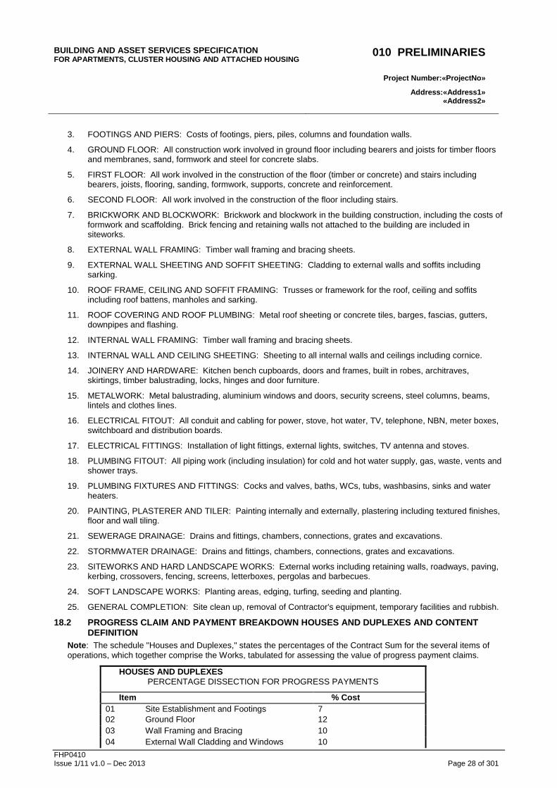
18.2 PROGRESS CLAIM AND PAYMENT BREAKDOWN HOUSES AND DUPLEXES AND CONTE NT DEFINITION
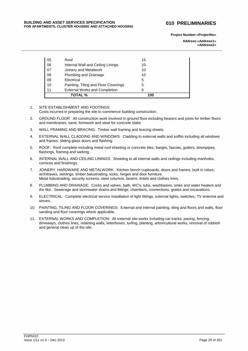
Note : The schedule "Houses and Duplexes," states the percentages of the Contract Sum for the several items of operations, which together comprise the Works, tabulated for assessing the value of progress payment claims.
HOUSES AND DUPLEXES PERCENTAGE DISSECTION FOR PROGRESS PAYMENTS
Item % Cost 01 Site Establishment and Footings 7 02 Ground Floor 12 03 Wall Framing and Bracing 10 04 External Wall Cladding and Windows 10
BUILDING AND ASSET SERVICES SPECIFICATION FOR APARTMENTS, CLUSTER HOUSING AND ATTACHED HOUSIN G
010 PRELIMINARIES
Project Number: «ProjectNo »
Address:«Address1» «Address2»
FHP0410 Issue 1/11 v1.0 – Dec 2013 Page 29 of 301
05 Roof 15 06 Internal Wall and Ceiling Linings 10 07 Joinery and Metalwork 10 08 Plumbing and Drainage 10 09 Electrical 5 10 Painting, Tiling and Floor Coverings 5 11 External Works and Completion 6 TOTAL % 100
1. SITE ESTABLISHMENT AND FOOTINGS: Costs incurred in preparing the site to commence building construction.
2. GROUND FLOOR: All construction work involved in ground floor including bearers and joists for timber floors and membranes, sand, formwork and steel for concrete slabs.
3. WALL FRAMING AND BRACING: Timber wall framing and bracing sheets.
4. EXTERNAL WALL CLADDING AND WINDOWS: Cladding to external walls and soffits including all windows and frames, sliding glass doors and flashing.
5. ROOF: Roof complete including metal roof sheeting or concrete tiles, barges, fascias, gutters, downpipes, flashings, framing and sarking.
6. INTERNAL WALL AND CEILING LININGS: Sheeting to all internal walls and ceilings including manholes, cornices and finishings.
7. JOINERY, HARDWARE AND METALWORK: Kitchen bench cupboards, doors and frames, built in robes, architraves, skirtings, timber balustrading, locks, hinges and door furniture. Metal balustrading, security screens, steel columns, beams, lintels and clothes lines.
8. PLUMBING AND DRAINAGE: Cocks and valves, bath, WC's, tubs, washbasins, sinks and water heaters and the like. Sewerage and stormwater drains and fittings, chambers, connections, grates and excavations.
9. ELECTRICAL: Complete electrical service installation of light fittings, external lights, switches, TV antenna and stoves.
10. PAINTING, TILING AND FLOOR COVERINGS: External and internal painting, tiling and floors and walls, floor sanding and floor coverings where applicable.
11. EXTERNAL WORKS AND COMPLETION: All external site works including car tracks, paving, fencing, driveways, clothes lines, retaining walls, letterboxes, turfing, planting, arboricultural works, removal of rubbish and general clean up of the site.
BUILDING AND ASSET SERVICES SPECIFICATION FOR APARTMENTS, CLUSTER HOUSING AND ATTACHED HOUSIN G
020 GENERAL REQUIREMENTS
Project Number: «ProjectNo »
Address:«Address1» «Address2»
FHP0410 Issue 1/11 v1.0 – Dec 2013 Page 31 of 301
020 GENERAL REQUIREMENTS
1 GENERAL
1.1 PRECEDENCE Precedence General: Schedules of Requirements of subsequent worksections of the specification override conflicting requirements in Part A of the specification.
1.2 CROSS REFERENCES Common requirements Associated worksections: Conform to the following:
- Adhesives, Sealants and Fasteners;
- Fire-Stopping;
- Metals and Prefinishes;
- Termite Management;
- Timber Finishes and Treatment; and
- applicable services worksections.
Associated schedules: Coordinate common requirements with the following:
- Contract Finalization Schedule in the Appendices (if applicable).
Cross referencing Within the text:
- Worksection titles are indicated by Italicised text.
- Clause titles are indicated by Bold text.
1.3 REFERENCED DOCUMENTS Contractual relationships General: Responsibilities and duties of the Principal, Contractor and Superintendent are not altered by requirements in the documents referenced in this specification.
Current editions General: Use referenced documents which are the editions, with amendments, current 3 months before the closing date for tenders, except where other editions or amendments are required by statutory authorities.
Site copies Special Conditions of Contract: Where reference to a Standard is required to resolve differences in respect of compliance with the Contract requirements, the Contractor shall provide a copy of the relevant Standard.
Environmental best practice references Where applicable, the Contractor shall meet the requirements of the following standards and documents:
- The Australian Environmental Labelling Association Standard No: AELA 23-2005
"Australian Voluntary Environmental Labelling Standard Architectural and Protective Coatings".
- South Coast Air Quality Management Rule 1168.
- AS/NZS 2269 Structural plywood.
- AS/NZS 2098 Methods of test for veneer and plywood.
- EN 13986:2001 Wood based panels for use in construction - Characteristics, evaluation of conformity and marking.
- EN717-1 Test reference standard for formaldehyde emission testing.
- AS 4708 Australian Forestry Certification Scheme.
- Forest Stewardship Council certification program.
1.4 INTERPRETATION Abbreviations General: For the purposes of this Contract the abbreviations given below apply.
- ABGR: Australian Building Greenhouse Rating.
- AFCS: Australian Forestry Certification Scheme.
- AFS: Australian Forestry Standard (AS 4808).
- AS: Australian Standard.
- ASHRAE: American Society of Heating, Refrigeration and Air-Conditioning Engineers.
- BCA: Building Code of Australia.
- BIM: Building information model.
- CFC: Compressed fibre cement.
- CIBSE: Chartered Institute of Building Services Engineers (UK).
- CSIRO CMSE: ActivFire Register of Fire Protection Equipment.
- DPC: Damp proof course.
- ESD: Environmentally Sustainable Design.
- FSC: Forest Stewardship Council.
- GBCA: Green Building Council of Australia.
- MS: Mild steel.
- MSDS: Material safety data sheets.
- NABERS: National Australian Built Environment Rating System.
- NATA: National Association of Testing Authorities.
- NZS: New Zealand Standard.
- PCA: Plumbing Code of Australia.
- PVC: Poly vinyl chloride.
- SS: Stainless steel.
- VOC: Volatile organic compound.
BUILDING AND ASSET SERVICES SPECIFICATION FOR APARTMENTS, CLUSTER HOUSING AND ATTACHED HOUSIN G
020 GENERAL REQUIREMENTS
Project Number: «ProjectNo »
Address:«Address1» «Address2»
FHP0410 Issue 1/11 v1.0 – Dec 2013 Page 32 of 301
Definitions General: For the purposes of this Contract the definitions given below apply.
- Approved: ‘Approved’, ‘reviewed’, ‘directed’, ‘rejected’, ‘endorsed’ and similar expressions mean ‘approved (reviewed, directed, rejected, endorsed) in writing by the Superintendent’.
- Attendance: ‘Attendance’, ‘provide attendance’ and similar expressions mean ‘give assistance for examination and testing’.
- Default: Specified value, product or installation method which is to be provided unless otherwise documented.
- Design life: The period of time for which it is assumed, in the design, that an asset will be able to perform its intended purpose with only anticipated maintenance but no major repair or replacement being necessary.
- Documented: ‘Documented’, ‘as documented’ and similar terms mean contained in the Contract documents.
- Economic life: The period of time from the acquisition of an asset to when the asset, while still physically capable of fulfilling its function and with only anticipated maintenance, ceases to be the lowest cost alternative for satisfying that function.
- Geotechnical site investigation: The process of evaluating the geotechnical characteristics of the site in the context of existing or proposed construction.
- Give notice: ‘Give notice’, ‘submit’, ‘advise’, ‘inform’ and similar expressions mean ‘give notice (submit, advise, inform) in writing to the Superintendent’.
- Hold point: The activity cannot proceed without the approval of the Superintendent.
- IP: ‘IP’, ‘IP code’, ‘IP rating’ and similar expression have the same meaning as ‘IP Code’ in AS 60529.
- Maintenance period: Synonymous with ‘Defects liability period’.
- Obtain: ‘Obtain’, ‘seek’ and similar expressions mean ‘obtain (seek) in writing from the Superintendent’.
- Metallic-coated: Steel coated with zinc or aluminium-zinc alloy as follows:
. Metallic-coated steel sheet: To AS 1397. Metal thicknesses specified are base metal thicknesses.
. Ferrous open sections zinc coated by an in-line process: To AS/NZS 4791.
. Ferrous hollow sections zinc coated by a continuous or specialised process: To AS/NZS 4792.
- Professional engineer: A person who is listed on the National Professional Engineers Register (NPER) in the relevant discipline at the relevant time.
- Proprietary: ‘Proprietary’ means identifiable by naming manufacturer, supplier, installer, trade name, brand name, catalogue or reference number.
- Provide: ‘Provide’ and similar expressions mean ‘supply and install’ and include development of the design beyond that documented.
- Registered testing authority:
. An organisation registered by the National Association of Testing Authorities (NATA) to test in the relevant field; or
. An organisation outside Australia registered by an authority recognised by NATA through a mutual recognition agreement; or
. An organisation recognised as being a Registered Testing Authority under legislation at the time the test was undertaken.
- Required: Means required by the documents, the local council or statutory authorities.
- If required: A conditional specification term for work which may be shown in the documents or be a legislative requirement.
- Samples: Includes samples, prototypes and sample panels.
- Supply: ‘Supply’, ‘furnish’ and similar expressions mean ‘supply only’.
- Tests:
. Pre-completion tests: Tests carried out before completion tests.
. Type tests: Tests carried out on an item identical with a production item, before delivery to the site.
. Production tests: Tests carried out on a purchased item, before delivery to the site.
. Site tests: Tests carried out on site.
. Completion tests: Tests carried out on completed installations or systems and fully resolved before the date for practical completion, to demonstrate that the installation or system, including components, controls and equipment, operates correctly, safely and efficiently, and meets performance and other requirements. The superintendent may direct that completion tests be carried out after the date for practical completion.
BUILDING AND ASSET SERVICES SPECIFICATION FOR APARTMENTS, CLUSTER HOUSING AND ATTACHED HOUSIN G
020 GENERAL REQUIREMENTS
Project Number: «ProjectNo »
Address:«Address1» «Address2»
FHP0410 Issue 1/11 v1.0 – Dec 2013 Page 33 of 301
- Tolerance: The permitted difference between the upper limit and the lower limit of dimension, value or quantity.
- Tolerance is an absolute value without a positive or a negative sign. It is commonly expressed by ‘± permitted deviation’ so that the value of the tolerance is implicit.
- Verification: Provision of evidence or proof that a performance requirement has been met or a default exists.
- Witness points: Provides an opportunity to attend an activity but does not involve an obligation. The activity can proceed without approval from the Superintendent.
1.5 CONTRACT DOCUMENTS Specification Part A and Part B The clauses contained in Part A of the specification apply to the project, where applicable, to meet the design intent, the Department’s required construction standards and mandatory authority requirements.
Specific project requirements, modification to the Part A clauses and selection of materials and systems are specified in the Schedules in Part B of the specification and/or on the drawings.
Any ambiguity between the Part A clauses, the Part B schedules and the drawings or any conflict with statutory requirements, must be referred to the Superintendent’s Representative immediately for clarification.
Levels Spot levels take precedence over contour lines and ground profile lines.
Permanent footpath levels at street alignment are to be to Local Government requirements. Reduced levels shown relate to a datum (key point) indicated on drawings.
1.6 SUBCONTRACT DOCUMENT Ensure that Subcontract and Supply Agreement tenderers are given or have a copy of all contract documents including:
- Specification including General Requirements and Schedules.
- Drawings and details.
- General and Special Conditions of Contract.
1.7 NOTICE Note The inspections listed in the following clauses do not include inspections for BSA Insurance purposes. These remain the responsibility of the Contractor. Department of Housing and Public Works officers are not authorised to perform inspections for insurance purposes.
Inspection Concealment: If notice of inspection is required in respect of parts of the works that are to be concealed, advise when the inspection can be made before concealment.
Minimum notice for inspections to be made: Allow reasonable notice for all inspections.
- 2 clear working days, for projects within 50 kms of the local Inspector’s office.
- 3 clear working days elsewhere, up to 200 kms.
- 5 clear working days for greater than 200 kms.
Light level requirements: to AS 1680.2.4.
Tests General: Give notice of the time and place of nominated tests.
Minimum notice for witnessing of tests to be made: Allow reasonable notice for all test inspections (minimum four hours for on-site inspectors, otherwise two working days or greater, depending on location and access arrangements).
Attendance General: Provide attendance for inspection and tests.
1.8 SUBMISSIONS Approval Do not commence work affected by samples until the samples have been approved. Submit further samples as necessary.
Retention Keep endorsed samples in good condition on site, until practical completion.
Match approved samples throughout the works.
Timing Submit documents and samples in a timely manner, to suit the construction program. Advise if any of the documents are to be returned.
Delays: Coordinate submissions of related items. Do not cause delays by making late or inadequate submissions.
Quantity Bound documents: 2 copies.
Loose documents up to and including A3: Two copies.
Loose documents larger than A3: Two copies the same size as the standard contract drawings.
Electronic Submission: Electronic submission of documentation is acceptable.
Design If part or all of an installation is to be designed by the contractor, submit documents showing the layout and details of the installation and certification if products must comply with product certification schemes or engineers certification.
BUILDING AND ASSET SERVICES SPECIFICATION FOR APARTMENTS, CLUSTER HOUSING AND ATTACHED HOUSIN G
020 GENERAL REQUIREMENTS
Project Number: «ProjectNo »
Address:«Address1» «Address2»
FHP0410 Issue 1/11 v1.0 – Dec 2013 Page 34 of 301
Variation documents: If it is proposed to change the installation from that shown on the contract documents, or if changes are required by statutory authorities, submit variation documents showing the proposed changes.
Samples: Submit a sample of each item where called for and 2 copies of supporting documentation. Include ancillary items such as fasteners, flashings and seals.
Errors General: If a submission contains errors, make a new or amended submission as appropriate, indicating changes made since the previous submission.
Identification Identify the project, Contractor, Subcontractor or supplier, manufacturer, applicable product, model number and options, as appropriate and include pertinent contract document references. Include service connection requirements and product certification. Identify proposals for non-compliance with project requirements, and characteristics which may be detrimental to successful performance of the completed work.
Endorsement Witness points: Give notice before commencing work affected by Contractor’s submissions, unless the submissions have been endorsed as satisfactory.
Hold points: Do not commence work affected by Contractor’s submissions until, if appropriate, the submissions have been endorsed as satisfactory.
Authorities Authorities’ approvals: Submit documents showing approval by the authorities whose requirements apply to the work.
Correspondence: Submit copies of correspondence and notes of meetings with authorities whose requirements apply to the work.
Incorporation of samples If it is intended to incorporate samples into the works, submit proposals.
Materials and components Unspecified products: If and when requested, for proprietary items, submit the manufacturer’s product data including:
- Technical specifications and drawings;
- Type test reports;
- Performance and rating tables; and
- Recommendations for installation and maintenance.
- Evidence of compliance, where products must comply with product certification schemes.
Substitution Identified proprietary items: Identification of a proprietary item does not necessarily imply exclusive
preference for the item so identified, but indicates the necessary properties of the item.
Alternatives: If alternatives to the documented products, methods or systems are proposed, submit sufficient information to permit evaluation of the proposed alternatives, including the following:
- Evidence that the performance is equal to or greater than that specified.
- Evidence of conformity to a cited standard.
- Samples.
- Essential technical information, in English.
- Reasons for the proposed substitutions.
- Statement of the extent of revisions to the contract documents.
- Statement of the extent of revisions to the construction program.
- Statement of cost implications including costs outside the Contract.
- Statement of environmental sustainability credentials of the proposed alternative product, method or system, including listing all implications for statutory and other government policy initiatives in regard to environmental sustainability.
- Statement of consequent alterations to other parts of the works.
Availability: If the documented products or systems are unavailable within the time constraints of the construction program, submit evidence.
Criteria: If the substitution is for any reason other than unavailability, submit evidence that the substitution:
- Is of net enhanced value to the Principal.
- Is consistent with the Contract documents and is as effectual as the identified item, detail or method.
Instruction Allow minimum 5 working days from submission of proposed alternatives for instruction from the Superintendent. If additional information is required, the Contractor shall provide this within 5 working days and shall allow a further 5 working days for instruction. If inadequate information is provided, or information is not provided in the required format, the alternative shall not be approved.
Incentives for substitution The Contractor is encouraged to source alternative materials which do not contain PVC or which contain a substantially-lower PVC content than those items specified.
Execution Embedded services: Submit proposals for embedding services in concrete walls or floors, or chasing into concrete or masonry walls.
BUILDING AND ASSET SERVICES SPECIFICATION FOR APARTMENTS, CLUSTER HOUSING AND ATTACHED HOUSIN G
020 GENERAL REQUIREMENTS
Project Number: «ProjectNo »
Address:«Address1» «Address2»
FHP0410 Issue 1/11 v1.0 – Dec 2013 Page 35 of 301
Acceptance of substrate: Submit installers’ statements verifying that the substrate is satisfactory for receiving the installation.
1.9 DESIGN General Design by Contractor: If the Contractor provides design, use only appropriately qualified persons and comply with all statutory requirements.
Conflict with the documents: If it is believed that a conflict exists between statutory requirements and the documents, notify the Superintendent immediately and provide a recommendation to resolve the conflict.
1.10 MANDATORY INSPECTIONS TO BE PROVIDED BY CONTRACTOR
The following inspection stages are mandatory. The contractor shall be responsible for engaging an independent and suitably competent person to undertake inspections and to issue a compliance certificate at the stages listed below. All costs associated with these requirements (including inspection and certification) will be at the contractor’s expense. The Contractor will notify the Superintendent of upcoming inspections 2 weeks prior to the inspection or activity occurring.
A “suitably competent person” is defined as either:
- A Registered Professional Engineer of Queensland acting within their field of competence and as registered.
- A nationally accredited building surveyor, accredited at level 1, 2 or 3 as appropriate to building being inspected.
- In respect of matters relevant to Fire Safety Installations, including passive fire barriers and active fire systems, a person holding the appropriate QBCC Fire Occupational Licence to “certify” the relevant Fire Safety Installation.
- In respect of any “aspect” of building work or building component installation (other than a fire safety installation) – the person responsible for the undertaking of that work, or installation of that component, who holds the appropriate QBCC Licence to undertake that work. Or where there is no QBCC licence, the relevant license from authority that regulates that class of work (eg electrical).
- Any other person as previously approved by the building surveyor responsible for the building assessment. Note – agreement as to the suitability and acceptability of the proposed person must be in place prior to the inspection being undertaken.
- As otherwise noted for specific inspection requirements nominated below.
A “compliance certificate” is defined as:
- a fully and correctly completed Form 16, or equivalent industry standard document;
- be signed by:
. the person holding the license; or
. in the case of a company;
. the “nominee” named on the license; or
. a person authorised in writing by the “nominee”;
- be issued in hard-copy in the “original” form or as an electronic document with a traceable electronic signature – not as a copy, scan or fax; and
- provided within 5 days of the relevant activity or inspection being completed.
Site inspection prior to commencing work Set-out of site:
- Prior to the commencement of excavations for footings.
- Inspection and Certificate to be by a Licensed Surveyor.
Footings and Compacted Ground:
- All necessary excavation organisation and placement of reinforcement prior to placement of permanent materials.
- Inspection and Certificate to be by a Registered Professional Engineer of Queensland.
Slab:
- Reinforcement in place; and
- Services positioned prior to placement of concrete.
- Inspection and Certificate to be by a Registered Professional Engineer of Queensland.
Suspended slab:
- All necessary formwork, block-outs, expansion joints, steel reinforcement, services and fire collars (and similar devices) installed prior to placement of concrete.
- Inspection to be undertaken by both:
. Inspection and Certificate to be by a Registered Professional Engineer of Queensland.
. And where applicable, a person holding a fire occupational licence relevant to each device required for the protection of slab penetrations.
Pre-Sheet:
- Frame complete.
- Roof complete with covering.
- All plumbing and electrical rough-in complete.
- External brick-veneer complete prior to internal lining.
BUILDING AND ASSET SERVICES SPECIFICATION FOR APARTMENTS, CLUSTER HOUSING AND ATTACHED HOUSIN G
020 GENERAL REQUIREMENTS
Project Number: «ProjectNo »
Address:«Address1» «Address2»
FHP0410 Issue 1/11 v1.0 – Dec 2013 Page 36 of 301
Fire Walls:
- For concrete walls (pre-cast, cast in-situ, tilt-up etc):
. With all formwork, block-outs, expansion joints, steel reinforcement, services and fire collars (and similar devices) installed prior to placement of concrete; and
. After stripping of formwork, or erection into location on site.
- For dry wall systems:
. Frame with all service rough-ins complete; and
. During sheeting operations.
- For concrete block wall systems:
. with all services rough-in complete, and block-outs, expansion joints, steel reinforcement, services and fire collars (and similar devices) installed prior to core-filling operations; and
. while core-filling is occurring.
Prior to Practical Completion: This inspection to be accompanied by issue to the Superintendent of:
- Queensland Fire and Emergency Services inspection completed (where relevant).
- Drainage Clearance Certificate from the relevant Local Government.
- all certificates from inspections as nominated above.
- installation compliance statements and test records for all services relevant to fire safety systems.
1.11 TESTS Provide and pay the costs of all labour, material and incidentals involved in specified tests.
Give the Superintendent sufficient notice so that designated tests may be witnessed.
Minimum notice:
- 2 working days for site tests; and
- 5 working days for local pre-delivery tests.
Testing authorities General: Except for site tests, have tests carried out by a registered testing authority and submit test reports.
Reports: Submit copies of test reports, including certificates for type tests, showing the observations and results of tests and conformance or non-conformance with requirements.
Site tests: Use instruments calibrated by authorities accredited by a registered testing authority.
Endorsement If tests are to be carried out on parts of the works, do not conceal those parts and do not commence further
work on those parts until the tests have been satisfactorily completed and compliance verified.
2 PRODUCTS
2.1 GENERAL Manufacturers’ or suppliers’ recommendations Provide, including select (if no selection is given), transport, deliver, store, handle, protect, finish, adjust and prepare for use, manufactured items in accordance with the current written recommendations and instructions of the manufacturer or supplier.
Proprietary items / systems / assemblies: Assemble, install or fix to substrate in accordance with the current written recommendations and instructions of the manufacturer or supplier.
Project modifications: Advise of activities that supplement, or are contrary to, manufacturers’ or suppliers’ written recommendations and instructions.
Sealed containers General: If materials or products are supplied by the manufacturer in closed or sealed containers or packages, bring the materials or products to point of use in the original containers or packages.
Sources policy General: Unless otherwise specified, use products manufactured in Australia or New Zealand, and comprising materials and components manufactured in Australia or New Zealand, unless no such products satisfy project requirements.
Advertising In addition to any other advertising for subcontract work and supplies, ensure advertisement in local and regional press.
2.2 PROPRIETARY ITEMS Definition: A proprietary item is any item identified by graphic representation on the Drawings, or by naming in the Specification and identified by one or more of the following:
- manufacturer; supplier; installer; applicator; trade name; product brand name; catalogue or reference number; and the like.
Use proprietary items in accordance with current manufacturer’s recommendations.
2.3 WORKMANSHIP Demolished and re-constructed any work considered inferior by the Superintendent.
2.4 ALTERNATIVE MATERIAL OR WORK Place orders for materials as soon as practicable and take all necessary measures to ensure delivery on time.
Where materials specified herein are unavailable or cannot reasonably be provided in time to meet the program, notify the Superintendent in writing immediately.
BUILDING AND ASSET SERVICES SPECIFICATION FOR APARTMENTS, CLUSTER HOUSING AND ATTACHED HOUSIN G
020 GENERAL REQUIREMENTS
Project Number: «ProjectNo »
Address:«Address1» «Address2»
FHP0410 Issue 1/11 v1.0 – Dec 2013 Page 37 of 301
If alternative products to those specified are proposed, the Contractor is to take responsibility for providing an equal alternative.
2.5 SELECTION AND HANDLING OF PRODUCTS
Where colours and finishes are involved, request approval of selection from the Superintendent.
Handle manufactured items with care and in accordance with the current written recommendations and instructions of the manufacturer or supplier.
Submit the manufacturer’s recommendations and instructions if requested by the Superintendent’s Representative, and advise of conflicts with other requirements.
Product certification: If products must comply with product certification schemes, use them in accordance with the certification requirements.
2.6 MATERIALS AND COMPONENTS Consistency General: For each material or product use the same manufacturer or source and provide consistent type, size, quality and appearance.
Protective coverings Protect the Works from the weather, dust and any cause during the progress of the Works. Remove all protective coverings on completion.
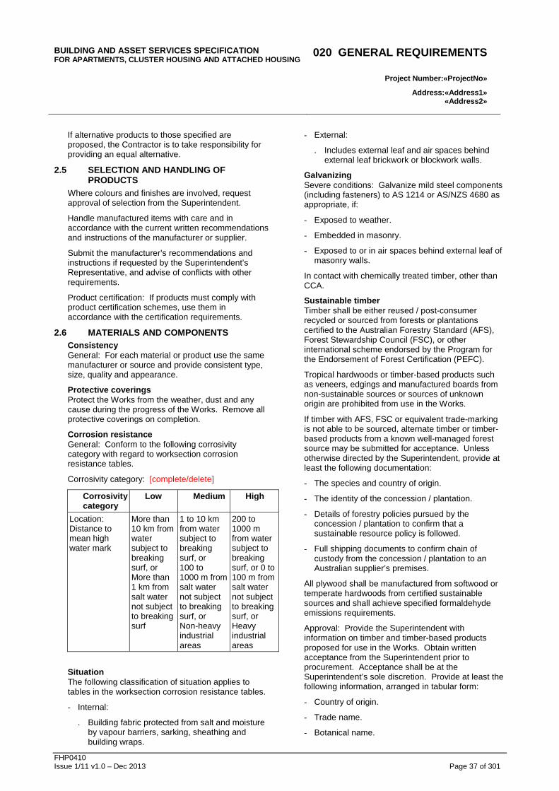
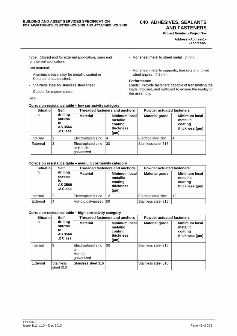
Corrosion resistance General: Conform to the following corrosivity category with regard to worksection corrosion resistance tables.
Corrosivity category: [complete/delete]
Corrosivity category
Low Medium High
Location: Distance to mean high water mark
More than 10 km from water subject to breaking surf, or More than 1 km from salt water not subject to breaking surf
1 to 10 km from water subject to breaking surf, or 100 to 1000 m from salt water not subject to breaking surf, or Non-heavy industrial areas
200 to 1000 m from water subject to breaking surf, or 0 to 100 m from salt water not subject to breaking surf, or Heavy industrial areas
Situation The following classification of situation applies to tables in the worksection corrosion resistance tables.
- Internal:
. Building fabric protected from salt and moisture by vapour barriers, sarking, sheathing and building wraps.
- External:
. Includes external leaf and air spaces behind external leaf brickwork or blockwork walls.
Galvanizing Severe conditions: Galvanize mild steel components (including fasteners) to AS 1214 or AS/NZS 4680 as appropriate, if:
- Exposed to weather.
- Embedded in masonry.
- Exposed to or in air spaces behind external leaf of masonry walls.
In contact with chemically treated timber, other than CCA.
Sustainable timber Timber shall be either reused / post-consumer recycled or sourced from forests or plantations certified to the Australian Forestry Standard (AFS), Forest Stewardship Council (FSC), or other international scheme endorsed by the Program for the Endorsement of Forest Certification (PEFC).
Tropical hardwoods or timber-based products such as veneers, edgings and manufactured boards from non-sustainable sources or sources of unknown origin are prohibited from use in the Works.
If timber with AFS, FSC or equivalent trade-marking is not able to be sourced, alternate timber or timber-based products from a known well-managed forest source may be submitted for acceptance. Unless otherwise directed by the Superintendent, provide at least the following documentation:
- The species and country of origin.
- The identity of the concession / plantation.
- Details of forestry policies pursued by the concession / plantation to confirm that a sustainable resource policy is followed.
- Full shipping documents to confirm chain of custody from the concession / plantation to an Australian supplier’s premises.
All plywood shall be manufactured from softwood or temperate hardwoods from certified sustainable sources and shall achieve specified formaldehyde emissions requirements.
Approval: Provide the Superintendent with information on timber and timber-based products proposed for use in the Works. Obtain written acceptance from the Superintendent prior to procurement. Acceptance shall be at the Superintendent’s sole discretion. Provide at least the following information, arranged in tabular form:
- Country of origin.
- Trade name.
- Botanical name.
BUILDING AND ASSET SERVICES SPECIFICATION FOR APARTMENTS, CLUSTER HOUSING AND ATTACHED HOUSIN G
020 GENERAL REQUIREMENTS
Project Number: «ProjectNo »
Address:«Address1» «Address2»
FHP0410 Issue 1/11 v1.0 – Dec 2013 Page 38 of 301
- Wood product volume category A (m³).
- Wood product volume category B (m³).
- Wood product volume category R (m³).
- Total volume (m³) where timber is:
. Category A: From an AFS, FSC or other certified forest or plantation endorsed by the PEFC.
. Category B: From a known certifiable forest.
Category R: Recycled material.
Formaldehyde minimization Unless otherwise approved by the Superintendent, use only engineered wood products, veneers and plywood products certified to contain minimal formaldehyde levels as nominated.
Compliance of engineered wood products: Type test to AS 4266.16 (2004) “Method 16: Formaldehyde emission-Dessicator method” to demonstrate formaldehyde levels equal to or less than:
- E1 – 1.0 mg/L.
Veneer and plywood products shall be tested to AS/NZS 2098.11 (2005) “Method 11: Methods of test for veneer and plywood – Determination of formaldehyde emissions for plywood” and shall also demonstrate a level equal to or lesser than the levels specified.
Hazardous materials The following materials shall not be used and, where found in a hazardous materials survey, shall be removed in accordance with current legislation.
- Asbestos or asbestos-containing products as defined in the:
. National Occupational Health & Safety Commission publication “Asbestos: Code of Practice and Guidance Notes” or any statutory modification or re-enactment thereof.
. Occupation Health & Safety (Asbestos) regulations 2003 or any later statutory modification or re-enactment thereof.
. Work Safe Australia Synthetic Mineral Fibre National Standard and National Code of Practice.
- Lead based paints and primers as defined in the:
. AS 4361 ‘Guide to Lead Paint Management.
. Australian Federal Government Department of Environment and Heritage Fact Sheet on Lead.
- Polychlorinated Biphenyls (PCB’s) as defined in the ANZECC Polychlorinated Biphenyls Management Plan.
3 EXECUTION
3.1 GENERAL Before commencing work on the contract, ascertain what restrictions, if any, apply to the various parts of the Works.
3.2 APPROVAL OF INSTALLER If the installation is required by a manufacturer’s approved installer, submit the manufacturer’s written approval of the installing firm to protect the product warranty.
3.3 DRILLING, CUTTING AND FASTENING The breaking or cutting of completed work must be avoided wherever possible.
No drilling, cutting or application of heat to structural or reinforcing steel is permitted except as expressly stated in these documents or for which later approval is given by the Superintendent.
Cutting or drilling of reinforced concrete must be only in positions and to the extent approved by the Superintendent.
Explosives powered fastenings shall not be of greater diameter or have greater penetration than permitted by the Superintendent.
3.4 INSTALLATION OF SERVICES Arrange services so that services running together are parallel with each other and with adjacent building elements.
Coordinate the various service trades in the location of service routes, openings, holes, chases and grooves and the positions of all floor outlets, traps, conduits, pipes, cables and the like in connection with the installation of work.
Exposed wall mounted services to be neatly grouped and covered with a pressed metal cover plate.
Under suspended ground floors, keep services at least 150 mm clear above ground surface, additional to insulation, and ensure access is not impeded.
3.5 SERVICES CONNECTIONS Statutory authorities’ requirements If the authorities elect to perform or supply part of the works, make the necessary arrangements.
Install equipment supplied, but not installed, by the authorities.
Connections Connect to statutory authorities’ services or service points. Excavate to locate and expose connection points. On completion reinstate the surfaces and facilities which have been disturbed.
3.6 BUILDING PENETRATIONS Piping sleeves General: Provide metal or UPVC sleeves formed from pipe sections, for piping penetrations through building elements.
BUILDING AND ASSET SERVICES SPECIFICATION FOR APARTMENTS, CLUSTER HOUSING AND ATTACHED HOUSIN G
020 GENERAL REQUIREMENTS
Project Number: «ProjectNo »
Address:«Address1» «Address2»
FHP0410 Issue 1/11 v1.0 – Dec 2013 Page 39 of 301
Finish: Prime paint ferrous surfaces.
Fire rated building elements Seal penetrations using a system to AS 4072.1.
Non-fire rated building elements Seal penetrations around conduits and sleeves. Seal around cables within sleeves.
If the building element is acoustic rated, maintain the rating.
Provide the approved termite barrier to penetrations through ground slabs.
Limitations General: Do not penetrate or fix to the following without approval:
- Structural building elements including external walls, fire walls, floor slabs and beams.
- Membrane elements including damp-proof courses, waterproofing membranes and roof coverings.
Termite barriers Membranes: If approval is given to penetrate membranes, provide a waterproof seal between the membrane and the penetrating component.
3.7 PIPING Cleaning Protection: Before installation, remove loose scale, burrs, fins and obstructions.
Installation General: Install piping in straight lines at uniform grades with no sags. Arrange to prevent air locks. Provide sufficient unions, flanges and isolating valves to allow removal of piping and fittings for maintenance or replacement of plant.
Arrangement: Arrange and support piping so that it remains free from vibrations whilst permitting necessary movements. Minimise the number of joints.
Spacing: Provide at least 25 mm clear between pipes and between pipes and building elements, additional to insulation.
Dissimilar metals: Join dissimilar metals using fittings of electrolytically compatible material.
3.8 VIBRATION SUPPRESSION General Minimise the transmission of vibration and noise from rotating, reciprocating and/or impacting equipment to other building elements. The operations are not to affect neighbouring properties.
3.9 FINISHES Piping General: Finish exposed piping, including fittings and supports, as follows:
- In internal locations such as toilet and kitchen areas: Chrome plate copper piping to AS 1192 service condition 2, bright.
- Externally, and steel piping and iron fittings internally: Paint.
- In concealed but accessible spaces (including cupboards and non-habitable enclosed spaces): Leave copper and plastic unpainted except for identification marking. Prime steel piping and iron fittings.
Valves: Finish valves to match connected piping.
3.10 MARKING Labels Type: Select from the following:
- For indoor applications only, engraved two-colour laminated plastic.
- Engraved and black filled lettering on stainless steel or brass, minimum thickness 1 mm.
- Cast metal.
Electrical Mark operable control devices, indicators, isolating switches and outlets to provide a ready means of identification.
4 COMPLETION
4.1 GENERAL Samples Remove unincorporated samples on completion.
Contractor’s submissions Within 2 weeks after practical completion, submit 3 copies of designated documents.
4.2 WARRANTEES General: Name the principal as warrantee. Register with manufacturers as necessary. Retain copies delivered with components and equipment.
Commencement: Commence warranty periods at practical completion or at acceptance of installation, if acceptance is not concurrent with practical completion.
Written warranties are required:
- where called for by the Contract Documents;
- on all items included the Schedules of Appliances and;
- where offered by the manufacturers.
Refer: Warranty Schedule at the end of this worksection.
4.3 FINAL CLEAN UP At the stage of Practical Completion and prior to handing over to the Superintendent::
- Remove temporary equipment, accommodation, hoardings and protective coverings. Disconnect
BUILDING AND ASSET SERVICES SPECIFICATION FOR APARTMENTS, CLUSTER HOUSING AND ATTACHED HOUSIN G
020 GENERAL REQUIREMENTS
Project Number: «ProjectNo »
Address:«Address1» «Address2»
FHP0410 Issue 1/11 v1.0 – Dec 2013 Page 40 of 301
and seal any temporary services unless otherwise required.
- Make good damage to adjoining properties, pathways, pavements, roadways, gutters and fencing caused by the execution of the Works.
- Clean and test all services and installations including drains and gutters, checking and oiling of all locks, hinges and moving parts of hardware, easing all doors and windows and rectify all defects.
- Employ professional cleaners to carry out the following cleaning work. Undertake by individual dwelling unit and after each unit is completed, lock up.
- Clean all windows, both inside and out.
- Remove all render or other spots on metal sashes, box sections and other surfaces.
- Dust all walls, ledges and projections, clean out all cupboards.
- Wash if necessary to clean all painted surfaces.
- Wash out and clean and dry wet area floors, fittings, mirrors, walls, sanitary fixtures, floor wastes and the like.
- Wash down all stairs.
- Clean and polish hardware, and laminated surfaces.
- Clean external surfaces and areas.
- Remove metal filings and the like from roofs.
- Remove all paints spots from floors and walls.
- Wash and dry all concrete floors and concrete slab areas.
- Clean and polish all hardware, ironmongery and other fittings.
- Clean out all ducts, cupboards, etc.
- Hand over to the Superintendent all keys properly tabulated to identify the same by room number or other appropriate title and having individually engraved labels.
Vermin Employ an approved firm of pest exterminators and provide a certificate from the firm stating that the complete building is free of vermin.
4.4 RECORD DRAWINGS Services Submit record hydraulics plan and other services drawings separately. Show dimensions, types and location of equipment, cables, piping and ductwork in relation to permanent site features and other underground services. Include relationship to building structure and other services, and changes made during commissioning and the maintenance period.
Format Submit electronic copies in AutoCAD or compatible format. Use the same borders and title block as the contract drawings. Template may be supplied by the Project Manager on application.
4.5 OPERATION AND MAINTENANCE MANUALS
General Submit 3 copies of final volumes of operation and maintenance manuals for installations with other required documentation at Practical Completion in accordance with the Handover Checklist.
Contents – general Include the following:
- Drawings and technical data: As necessary for the efficient operation and maintenance of the installation.
- Equipment descriptions:
. Name, address and telephone and facsimile numbers of the manufacturer and supplier of items of equipment installed, together with catalogue list numbers.
. Schedules (system by system) of equipment, stating locations, duties, performance figures and dates of manufacture. Provide a unique code number cross-referenced to the record and diagrammatic drawings and schedules, including spare parts schedule, for each item of equipment installed.
- Maintenance procedures:
. Manufacturer’s technical literature as appropriate. Register with manufacturer as necessary. Retain and hand over in the manual, copies delivered with appliances and equipment.
. Safe trouble-shooting, disassembly, repair and reassembly, cleaning, alignment and adjustment, balancing and checking procedures. Provide logical step-by-step sequence of instructions for each procedure.
- Drawings:
. Record drawings, full size.
4.6 TRAINING Operation Immediately after practical completion, explain and demonstrate to the principal’s staff the purpose, function and operation of the installations.
Maintenance Immediately after practical completion, explain and demonstrate to the principal’s staff the purpose, function and maintenance of the installations.
4.7 COMPLETION TESTS General Carry out acceptance tests and final tests.
BUILDING AND ASSET SERVICES SPECIFICATION FOR APARTMENTS, CLUSTER HOUSING AND ATTACHED HOUSIN G
020 GENERAL REQUIREMENTS
Project Number: «ProjectNo »
Address:«Address1» «Address2»
FHP0410 Issue 1/11 v1.0 – Dec 2013 Page 41 of 301
Hydraulic site tests Preparation for pressure testing: Securely anchor pipes and fittings in position to prevent movement during tests. Leave pipe joints exposed to enable observation during tests. Disconnect equipment which is not designed to carry the test pressure.
4.8 MAINTENANCE General General: During the maintenance period, carry out periodic inspections and maintenance work as recommended by manufacturers of supplied equipment, and promptly rectify faults.
Emergencies: Attend emergency calls promptly.
Maintenance records Referenced documents: If referenced documents or technical sections require that log books or records be submitted, include this material in the maintenance records.
Certification: On satisfactory completion of the installation, submit certificates stating that each installation is operating correctly.
BUILDING AND ASSET SERVICES SPECIFICATION FOR APARTMENTS, CLUSTER HOUSING AND ATTACHED HOUSIN G
030 ENVIRONMENTAL REQUIREMENTS
Project Number: «ProjectNo »
Address:«Address1» «Address2»
FHP0410 Issue 1/11 v1.0 – Dec 2013 Page 43 of 301
030 ENVIRONMENTAL REQUIREMENTS
1 GENERAL
1.1 OUTLINE DESCRIPTION Application This worksection applies to all activities associated with work under the Contract which are required to be undertaken in compliance with the Environmental Protection Act 1994 and subordinate legislation, and with due regard to health and safety requirements associated with such work.
1.2 CROSS REFERENCES General Refer to the General Requirements worksection.
2 EXECUTION
2.1 STATUTORY REQUIREMENTS General Comply with the following as applicable:
- Environmental Protection Regulation (Nuisance Provisions) 2000 as amended.
- Cultural Record (Landscapes Queensland and Queensland Estate) Act 1987.
- Queensland Heritage Act 1992.
Reference guidelines Soil and Sediment Control - Engineering Guidelines for Queensland Construction Sites The Institution of Engineers, Australia (Queensland Division).
2.2 CONSTRUCTION MANAGEMENT PLAN (ENVIRONMENTAL)
Submission Prepare a Construction Management Plan for the site:
- detailing the planned sequence, methodology and program proposed for undertaking and environmental management of all work under the Contract; and
- conforming to the requirements of the Contract.
Submit the Construction Management Plan to the Superintendent within 7 days of the date of the Letter of Acceptance, or at such later time as might be
agreed, and prior to proceeding with any work under the Contract.
Liability of Principal limited Receipt of the Construction Management Plan shall in no way relieve the Contractor of responsibility under the Contract to ensure compliance with environmental legislation and any approvals issued by the Environmental Protection Agency or other statutory authority as may be required in respect to work under the Contract.
Details Address, as a minimum requirement, the following topics in the Construction Management Plan:
- order of work under the Contract;
- Soil Erosion and Sediment Control Plan;
- earthworks controls;
- Stock Piling Area Plan;
- dust control;
- noise control;
- weed control;
- temporary fencing, barricading and/or other access controls;
- temporary sanitary and waste services;
- storage of plant and materials, including any chemicals, fuels or other hazardous substances;
- engagement of a competent Environmental Officer;
- environmental training of employees and subcontractors where appropriate;
- any other items necessary to protect the surrounding environment.
Audits The Superintendent may undertake, or direct, audits of the work under the Contract against the accepted Construction Management Plan (Environmental), the Specification, and legislation, at any time. The Contractor shall bring the work under the Contract into compliance with all Contractual requirements, if necessary, within the time notified after the audit.
2.3 ENVIRONMENTAL HARM OR BREACHES Responsibility If an incident or non-compliance occurs, which may constitute an environmental harm or breach under the provisions of the Environmental Protection Act, immediately attend to the incident or non-compliance. Contain or prevent the likelihood of an environmental harm or breach, and protect public health and safety.
Notify the Superintendent immediately that such an incident or non-compliance occurs. Register each such incident with the Environmental Protection Agency and any other relevant statutory authority as necessary.
BUILDING AND ASSET SERVICES SPECIFICATION FOR APARTMENTS, CLUSTER HOUSING AND ATTACHED HOUSIN G
030 ENVIRONMENTAL REQUIREMENTS
Project Number: «ProjectNo »
Address:«Address1» «Address2»
FHP0410 Issue 1/11 v1.0 – Dec 2013 Page 44 of 301
Restoration If an incident or non-compliance occurs, comply with directions given by all relevant statutory authorities and the Superintendent, whether or not an environmental harm or breach is deemed to have occurred.
All costs and delays, including those related to restoration, that result from the incident or non-compliance shall be wholly borne by the Contractor, if the Principal determines that the incident or non-compliance resulted from an act or omission of the Contractor.
2.4 GENERAL ENVIRONMENTAL CONTROLS Dust control Restrict dust caused by the Works to a minimum.
Noise control Take all practical precautions to minimise noise resulting from work under the Contract. Fit all construction equipment with noise suppressors and manage use of construction equipment so noise is minimised.
Runoff Control runoff to minimise sediment loss from the site and pollution of natural waterways and municipal drainage systems. Additionally, comply with specific Local Authority requirements in addition to governing statutory requirements.
Fire protection Burning of refuse or other materials or lighting of any fires is not permitted.
Storage on site Store materials and equipment on site to prevent damage to the site and minimise hazards to persons, materials and equipment. Keep storage areas neat and tidy.
Site activities Do not form new tracks, alter existing tracks, erect camps, remove trees or shrubs, cut fences, water, sewerage, power or telecommunication lines, or perform other activities not specified or indicated on the drawings or otherwise required under the Contract without prior approval by the Superintendent.
Disposal of wastes Dispose of all construction wastes, site refuse and any solid or liquid contaminants resulting from work under the Contract in accordance with statutory and local authority requirements.
2.5 EXISTING FLORA Protection Protect from damage all trees and other plants which:
- are shown or specified to be retained; or
- need not be removed or damaged for construction operations.
2.6 VEGETATION CLEARING Extent Contain the extent of vegetation clearing to the limits specified or indicated on the drawings or otherwise approved by the Superintendent.
Disposal Unless otherwise approved, no off-site disposal or burning of cleared vegetation is permitted. Put all cleared vegetation through a chipper and stockpile for re-use as mulch where directed. Materials may be reused in conjunction with environmental control measures if suitable. Dispose of excess or unwanted material in accordance with Local Authority requirements and guidelines.
2.7 SOIL EROSION AND SEDIMENT CONTROL
General Undertake all work under the Contract to prevent erosion, contamination and sedimentation of the site, surrounding areas and drainage systems. Do not commence work on site prior to submitting a Soil Erosion and Sediment Control Plan to the Superintendent.
Control measures Adopt such control measures as may be necessary, including the following where applicable:
- staging of operations and sequence of work under the Contract (eg clearing, stripping, rehabilitation);
- restoration of disturbed areas in progress with the work under the Contract;
- use of mulch materials to protect disturbed or exposed areas where suitable;
- provision of temporary drains and catch drains;
- application of diversion, dispersal and/or retention measures to concentrated flows to control and dissipate stormwater through the site without damage;
- spreader banks or other structures to disperse concentrated runoff;
- silt traps to prevent discharge sediment material to downstream areas;
- temporary grassing or other treatments (eg contour ploughing/bunding) to disturbed areas and long term stockpiles; and
- silt fencing.
Maintenance Continually inspect and maintain control measures throughout the course of the work under the Contract and during the Defects Liability Period, and following each incidence of rain. Rearrange and reposition control measures as required to maintain their efficacy. Handle and dispose of sediment collected by control measures in an approved manner.
BUILDING AND ASSET SERVICES SPECIFICATION FOR APARTMENTS, CLUSTER HOUSING AND ATTACHED HOUSIN G
030 ENVIRONMENTAL REQUIREMENTS
Project Number: «ProjectNo »
Address:«Address1» «Address2»
FHP0410 Issue 1/11 v1.0 – Dec 2013 Page 45 of 301
Removal Remove all temporary control measures following rehabilitation or when otherwise no longer required.
2.8 IMPORTED SOIL MATERIALS Testing Imported soil materials shall be sampled and tested or otherwise obtained from a certified source as being free from contaminants. Testing from non-certified sources shall be at a minimum rate of 1 sample per 50 m3 or as otherwise approved by the Environmental Protection Agency or Superintendent. Supply all test results and/or certificates to the Superintendent for verification prior to any site delivery of materials.
2.9 HEALTH PROTECTION Precautions Take the precautions necessary to protect the health of persons on or within the vicinity of the site from conditions which are or may be dangerous to health, including the noxious effects of dust, fumes, liquids, infection, fire explosion or other hazards.
Hazardous materials Notify the Superintendent immediately if any of the following are found:
- asbestos and asbestos-containing materials;
- flammable or explosive liquids or gases;
- toxic, infective or contaminated materials;
- noxious or explosive chemicals; and
- tanks or other containers which have been used for storage of explosives, toxic, infective or contaminated substances.
BUILDING AND ASSET SERVICES SPECIFICATION FOR APARTMENTS, CLUSTER HOUSING AND ATTACHED HOUSIN G
040 ADHESIVES, SEALANTS AND FASTENERS
Project Numbe r:«ProjectNo »
Address:«Address1» «Address2»
FHP0410 Issue 1/11 v1.0 – Dec 2013 Page 47 of 301
040 ADHESIVES, SEALANTS AND FASTENERS
1 GENERAL
1.1 CROSS REFERENCES General Refer to the General Requirements worksection.
Related worksections Conform to the relevant related worksections.
1.2 SUBMISSIONS Installed sealant tests Sampling: For each sealant test take 3 samples of installed and cured sealant, each at least 50 mm long, from completed joints.
Testing: Submit the results of tests to the Installed sealant tests schedule .
Reinstatement: Make good the joints from which the samples were taken.
Installed sealant tests schedule Item to be tested
Property to be tested
Applicable standard
Sealants Samples: Submit colour samples of visible joint sealants.
Documents: Submit technical data sheets.
1.3 INSPECTION Notice Inspection: Give notice so that inspection may be made of joints and penetrations prepared for the application of sealants to the Installed sealant tests schedule .
1.4 PERFORMANCE Adhesives and sealants General: Provide adhesives and sealants capable of transmitting imposed loads, sufficient to ensure the rigidity of the assembly, or integrity of the joint and which will not cause discolouration of finished surfaces.
Compatibility: Do not use sealants or adhesives that are incompatible with the products to which they are applied.
Movement: Where an adhered or sealed joint may be subject to movement, select a system accredited to accommodate the projected movement under the conditions of service.
Refurbishment: Use sealants that can be safely removed and prepared for refurbishment.
Fasteners Provide fasteners accredited for the particular use, capable of transmitting imposed loads and maintaining the rigidity of the assembly.
2 PRODUCTS
2.1 ADHESIVES Standards Mastic adhesive: To AS 2329.
Polymer emulsion adhesive for timber: To AS 2754.2, not inferior to Type 3.
High strength adhesive tape General description: A foam of cross linked polyethylene or closed cell acrylic coated both sides with a high performance acrylic adhesive system, encased in release liners of paper or polyester.
Product classification: Ensure product suitability for the following substrates:
- Firm high strength foam tapes for high energy surfaces including most bare metals such as stainless steel and aluminium.
- Conformable high strength foam for medium energy surfaces including many plastics and paints, and bare metals.
- Conformable high strength foam for lower energy surfaces including many plastics, most paints and powder coatings, and bare metals.
Thickness: Select the tape to ensure a mismatch between surfaces does not exceed half the tape thickness under the applied lamination pressure.
2.2 SEALANTS Standards General: To ISO 11600.
External masonry joints General: Provide sealant and bond breaking backing materials compatible with each other and the substrate and which are non-staining to masonry. Do not use bituminous materials with absorbent masonry units.
Bond breaking backing:
- Bond breaking materials: Non-adhesive to sealant, or faced with a non-adhering material.
- Foamed materials: Closed-cell or impregnated, not water-absorbing.
Fire rated control joints General: Provide sealant materials that maintain the nominated fire resistant rating.
Fire stopping: To AS 4072.1.
BUILDING AND ASSET SERVICES SPECIFICATION FOR APARTMENTS, CLUSTER HOUSING AND ATTACHED HOUSIN G
040 ADHESIVES, SEALANTS AND FASTENERS
Project Numbe r:«ProjectNo »
Address:«Address1» «Address2»
FHP0410 Issue 1/11 v1.0 – Dec 2013 Page 48 of 301
Pointing and bedding General: Provide sealants for fast moving joints in light weight building elements that are compatible with the contact materials.
Bond breaking backing:
- Bond breaking materials: Non-adhesive to sealant, or faced with a non-adhering material.
- Foamed materials: Closed-cell or impregnated, not water-absorbing.
Floor movement joints General: Provide trafficable sealants for that are compatible with the contact materials.
Bond breaking backing:
- Bond breaking materials: Non-adhesive to sealant, or faced with a non-adhering material.
- Foamed materials: Closed-cell or impregnated, not water-absorbing.
2.3 FASTENERS General Masonry anchors: Proprietary expansion or chemical type.
Plain washers: To AS 1237.1.
- Provide washers to the heads and nuts of bolts, and the nuts of coach bolts.
Plugs: Proprietary purpose-made plastic.
Powder-actuated fasteners: To AS/NZS 1873.4.
Stainless steel fasteners: To ASTM A240/240M.
Steel nails: To AS 2334.
- Length: At least 2.5 x the thickness of the member being secured, and at least 4 x the thickness if the member is plywood or building board < 10 mm thick.
Unified hexagon bolts, screws and nuts: To AS/NZS 2465.
Fasteners in CCA treated timber: Epoxy coated or stainless steel.
Bolts Coach bolts: To AS/NZS 1390.
Hexagon bolts Grades A and B: To AS 1110.1.
Hexagon bolts Grade C: To AS 1111.1.
Corrosion resistance Corrosivity category: To the General Requirements worksection.
Steel products: Conform to the Corrosion resistance table or provide proprietary products with metallic and/or organic coatings of equivalent corrosion resistance.
Fixing of aluminium balustrades Stainless 316.
Finishes Electroplating:
- Metric thread: To AS 1897.
- Imperial thread: To AS 4397.
Galvanizing:
- Threaded fasteners: To AS 1214.
- Other fasteners: To AS/NZS 4680.
Mild steel fasteners: Galvanize if:
- Embedded in masonry.
- In external timbers.
- In contact with chemically treated timber, other than CCA treated timber.
Epoxy coated:
- CCA Treated timber.
Nuts Hexagon chamfered thin nuts Grades A and B: To AS 1112.4.
Hexagon nuts Grade C: To AS 1112.3.
Hexagon nuts Style 1 Grades A and B: To AS 1112.1.
Hexagon nuts Style 2 Grades A and B: To AS 1112.2.
Screws Coach screws: To AS/NZS 1393.
Hexagon screws Grades A and B: To AS 1110.2.
Hexagon screws: Grade C To AS 1111.2.
Hexagon socket screws: To AS/NZS 1421.
Machine screws: To AS/NZS 1427.
Self-drilling screws: To AS 3566.1 and AS 3566.2.
Self-tapping screws:
- Crossed recessed countersunk (flat – common head style): To AS/NZS 4407.
- Crossed recessed pan: To AS/NZS 4406.
- Crossed recessed raised countersunk (oval): To AS/NZS 4408.
- Hexagon: To AS/NZS 4402.
- Hexagon flange: To AS/NZS 4410.
- Hexagon washer: To AS/NZS 4409.
- Slotted countersunk (flat – common head style): To AS/NZS 4404.
- Slotted pan: To AS/NZS 4403.
- Slotted raised countersunk (oval – common head style): To AS/NZS 4405.
Blind rivets Description: Expanding end type with snap mandril.
BUILDING AND ASSET SERVICES SPECIFICATION FOR APARTMENTS, CLUSTER HOUSING AND ATTACHED HOUSIN G
040 ADHESIVES, SEALANTS AND FASTENERS
Project Numbe r:«ProjectNo »
Address:«Address1» «Address2»
FHP0410 Issue 1/11 v1.0 – Dec 2013 Page 49 of 301
Type: Closed end for external application, open end for internal application.
End material:
- Aluminium base alloy for metallic coated or Colorbond coated steel.
- Stainless steel for stainless steel sheet.
- Copper for copper sheet.
Size:
- For sheet metal to sheet metal: 3 mm.
- For sheet metal to supports, brackets and rolled steel angles: 4.8 mm.
Performance Loads: Provide fasteners capable of transmitting the loads imposed, and sufficient to ensure the rigidity of the assembly.
Corrosion resistance table – low corrosivity catego ry Situation
Self drilling screws to AS 3566.2 Class
Threaded fasteners and anchors Powder actuated fasteners
Material Minimum local metallic coating thickness (µm)
Material grade Minimum local metallic coating thickness ( µm)
Corrosion resistance table – high corrosivity categ ory Situation
Self drilling screws to AS 3566.2 Class
Threaded fasteners and anchors Powder actuated fasteners
Material Minimum local metallic coating thickness (µm)
Material grade Minimum local metallic coating thickness ( µm)
Internal 3 Electroplated zinc or Hot-dip galvanized
30 Stainless steel 316
External Stainless steel 316
Stainless steel 316 Stainless steel 316
BUILDING AND ASSET SERVICES SPECIFICATION FOR APARTMENTS, CLUSTER HOUSING AND ATTACHED HOUSIN G
050 METALS AND PREFINISHES
Project Number: «ProjectNo »
Address:«Address1» «Address2»
FHP0410 Issue 1/11 v1.0 – Dec 2013 Page 51 of 301
050 METALS AND PREFINISHES
1 GENERAL
1.1 CROSS REFERENCES General Refer to the General Requirements worksection.
Related worksections Refer to the following worksections:
- Structural Steel;
- Metal Fixtures;
- Doors and Hatches;
- Windows;
- Landscaping;
- Brick and Blockwork;
- Light Timber Framing;
- Light Steel Framing;
Etc.
2 MATERIALS AND COMPONENTS
2.1 METALS Steel Structural bars and sections: To AS/NZS 3679.1.
Sheet: To AS/NZS 1595.
Steel for prefinishes Electric Resistance Welded (ERW) pipe: To AS 1450 “bright”.
Cold rolled bar: To AS 1443 “bright”.
Cold rolled sheet: To AS 1595.
- Designation: CA2S-E.
Coated steel Galvanized structural hollow sections: To AS 1163.
(Note: Manufactured hollow section components to be fully galvanised inside and out after fabrication.
Site Welding: Not permitted. Joining of galvanized components on site to be by mechanical means only.
See relevant worksections).
Zinc-coated sheet: To AS 1397.
- Coating class for sheet: Comply with the recommendations of AS 1397 Appendix D.
- Perforated metal sheet to be zinc coated after perforating or cutting and prior to powder coating or other pre-finishing.
Thickness: Metal thicknesses specified are base metal thicknesses.
Stainless steel Plate, sheet and strip: To ASTM A A240/A 240M.
Bars: To ASTM A 276.
Welded pipe (round): To AS 1769.
Welded pipe (square): To ASTM A 554.
Type: >
Aluminium and aluminium alloys Drawn rod, bar and strip: To AS/NZS 1865.
Extrusions: To AS/NZS 1866.
Drawn pipe: To AS/NZS 1867.
Plate and sheets: To AS/NZS 1734.
3 METAL FINISHING
3.1 WORKMANSHIP Preparation General: Before applying decorative or protective prefinishes to metal components, complete welding, cutting, drilling and other fabrication, and prepare the surface using a suitable method.
Standard: To AS 1627.
Priming steel surfaces: Where site painting is specified to otherwise uncoated mild steel or similar surfaces:
- prime after fabrication and before delivery to the works; and
- after installation, repair damaged priming and complete the coverage to unprimed surfaces.
Welding Steel: To AS/NZS 1554.1.
Aluminium: To AS 1665.
Stainless steel: To AS/NZS 1554.6.
Brazing General: Ensure brazed joints have sufficient lap to provide a mechanically sound joint. For butt joints do not rely on the filler metal fillet only.
Filler metal: To AS 1167.1.
Finishing Site welding is not permitted.
Visible joints: Finish visible joints made by welding, brazing or soldering using methods appropriate to the class of work (including grinding or buffing) before further treatment such as painting, galvanizing or electroplating. Ensure self-finished metals are without surface colour variations after jointing.
3.2 ELECTROPLATING Electroplated coatings Zinc on iron or steel: To AS 1789.
Chromium on metals: To AS 1192.
Nickel on metals: To AS 1192.
Service condition number: At least 2.
GALVANIZING
BUILDING AND ASSET SERVICES SPECIFICATION FOR APARTMENTS, CLUSTER HOUSING AND ATTACHED HOUSIN G
050 METALS AND PREFINISHES
Project Number: «ProjectNo »
Address:«Address1» «Address2»
FHP0410 Issue 1/11 v1.0 – Dec 2013 Page 52 of 301
Galvanizing Fabricated ferrous articles: To AS/NZS 4680.
Ferrous hollow sections by a continuous or specialised process: To AS/NZS 4792.
- Minimum coating class: HDG300.
Ferrous open sections by an in-line process: To AS/NZS 4791.
- Minimum coating class: ILG200.
Steel wire: To AS/NZS 4534.
- Minimum coating class: W10Z.
Components in contact with concrete Passivate galvanized surfaces to be cast into or in contact with concrete by dipping in 0.2% sodium dichromate solution.
3.3 ANODISING Anodising Standard: To AS 1231.
Class:
- Indoor applications: At least AA10.
- Outdoor applications: At least AA25.
3.4 POWDER COATING Thermoset powder coating Standards: To AS 3715 or AS/NZS 4506, as appropriate.
Internal use: APAS-P-155/1 or 4.
External use: APAS-P-155/2 or 5.
Finish: Full gloss.
Preparation General: Use chemical pretreatments. If recommended, provide conversion coatings.
Unprotected steel: Remove rust to AS 1627.4 Class 2½, clean by immersing in trichloroethylene or an alkaline solution, and apply a coat of iron phosphate.
Galvanized steel: Clean by immersing in a suitable alkaline or acidic solution, apply a zinc phosphate chemical conversion coating, rinse and degrease.
Aluminium: Pretreat as recommended in AS 3715 Appendix B, including the application of a conversion coating.
3.5 PREPAINTING Prepainted metal products Standard: To AS/NZS 2728.
Product type: Not lower than the type appropriate to the field of application.
Product finish: Refer to trade worksections and Schedule of Materials and Finishes in Multi Trade Schedules.
BUILDING AND ASSET SERVICES SPECIFICATION FOR APARTMENTS, CLUSTER HOUSING AND ATTACHED HOUSIN G
060 TERMITE CONTROL
Project Nu mber: «ProjectNo »
Address:«Address1» «Address2»
FHP0410 Issue 1/11 v1.0 – Dec 2013 Page 53 of 301
060 TERMITE CONTROL
1 GENERAL
1.1 CROSS REFERENCES General Refer to the General Requirements worksection.
Related worksections Refer to the following worksections:
- Concrete;
- Brick and Block Construction.
1.2 STANDARD General Termite barriers: To AS 3660.1.
2 QUALITY
2.1 INSPECTION Witness points Give sufficient notice so that inspection may be made of the completed termite barriers by the supplier.
3 MATERIALS AND COMPONENTS
3.1 PHYSICAL BARRIERS Concrete slab barrier Standard: To AS 3660.1 Section 4.
Cap and strip shields Projection: Install so that no edge is less than 55 mm from the vertical face of the wall or pier.
Material: Galvanized steel.
3.2 PROPRIETARY SLAB ON GROUND SYSTEMS
Woven stainless steel mesh barriers Standard: To AS 3660.1 Section 6.
Graded stone particles barriers Standard: To AS 3660.1 Section 7.
Capping for graded particle systems Reinforced Concrete Strip 450mm x 100mm deep, Broom finish with tooled edge.
Slab services penetrations Barrier type: Same as perimeter treatment or a tested and approved total system component.
Product appraisal Mandatory requirement: Termite Control Systems used are to hold a current Code Mark or Certificate of Conformity including the expected life of the installation of at least 50 years required under the Queensland variation to the BCA.
Physical barriers with a chemical impregnation (composite products) Mandatory requirement: Contractor to provide a Material Safety Data Sheet declaring the product is not classified as hazardous according to the criteria
of National Occupational Health and Safety Commission Australia and not a dangerous good according to the Australian Dangerous Goods code.
4 INSTALLATION
4.1 PHYSICAL BARRIERS Provide the physical barrier to the manufacturer’s recommendations to protect:
- Service Penetrations.
- Cavity brick walls including internal leaf gaps.
- 200 concrete blockworks/retaining walls.
- Brick veneer walls.
- Joins in the concrete slab.
- Junctions with external paving where paving is less than 75mm below floor slab or weep holes.
- Any location required to complete the installation.
Extent Use a proprietary system installed as a Physical Barrier for a “Partial Installation” - Perimeter and penetrations to the requirements of AS 3660.
Approved Subcontractors The work must be performed by an approved specialist subcontractor, approved and licensed by the manufacturer.
Certification Furnish a Certificate and a warranty satisfactory to the Principal from the subcontractor to the Principal.
4.2 APPLIED CHEMICAL SOIL BARRIERS Not to be used in new construction.
5 COMPLETION
5.1 COMPLETION Termite barrier notice Provide 2 No. durable notices. One to be permanently fixed in a prominent location in accordance with BCA Volume 1 Part B14 (i) (ii). The other to be included in the project Maintenance Manual along with the warranty.
Warranty Terms: Provide a warranty in accordance with AS 3660.1 valid for a period of 10 years and covering:
- Reinstallation necessitated by termite attack.
- Replacement of timber attacked by termites.
- Removal and reinstatement of building contents, whether built-in or not, as necessary to replace affected timber.
Completion inspection At the end of the defects liability period, inspect the termite control systems and submit a report on their efficacy and status.
BUILDING AND ASSET SERVICES SPECIFICATION FOR APARTMENTS, CLUSTER HOUSING AND ATTACHED HOUSIN G
070 TIMBER FINISHES AND TREATMENT
Project Number: «ProjectNo »
Address:«Address1» «Address2»
FHP0410 Issue 1/11 v1.0 – Dec 2013 Page 55 of 301
070 TIMBER FINISHES AND TREATMENT
1 GENERAL
1.1 CROSS REFERENCES General Refer to the General Requirements worksection.
Related worksections Refer to the following worksections:
- Light Timber Framing;
- Timber Fixtures;
- Fencing;
- Landscape;
- Schedule of Materials and Finishes.
1.2 INTERPRETATION Definitions Plywood: To AS/NZS 4491.
“Standard trade common names”: To AS 1148 and AS 2543.
Groups of timbers: Terms employed for that purpose in relevant Australian standards.
Pressure preservative treatment: For timber required to be pressure treated, submit a certificate or other satisfactory evidence showing that the timber has been treated.
3 MATERIALS
3.1 TIMBER Durability General: Provide preservative-treated timber as documented. If preservative-treated timber is not documented, provide timbers having natural durability appropriate to the conditions of use, or preservative-treated timber of equivalent durability.
Natural durability classification: To AS 5604.
Timber quality: Free of core wood (material within 50 mm of the tree’s centre) and free of splits, checks, loose knots and cavities. Free of sapwood (lighter coloured wood found on the outer layer of the tree.
Lyctus susceptible timbers Do not provide timbers containing Lyctus susceptible sapwood.
Preservative treatment Standard: To AS 1604.
Hazard classification: H3 or as otherwise documented.
CCA preservative: Type I.
Water-repellent treatment Repellent: To APAS-M-96.
Moisture content Tolerance: Make milled and dressed products from timbers seasoned:
- to within 3% of the equilibrium moisture content appropriate to the timber and its intended conditions of use;
- to 10 - 15% moisture content; and
- with no more than 3% difference between any 2 pieces in any one group.
Test: To AS/NZS 1080.1.
Protection: Protect timber and timber products stored on site from moisture and weather. For milled, prefinished, prefabricated and similar elements which are protected in the final structure, provide temporary weather protection until the permanent covering is in place.
Finished sizes General: Provide milled timbers with actual dimensions which are at least the stated dimensions, except for dimensions qualified by a term such as “nominal” or “out of” to which industry standards for finished sizes apply.
Unseasoned timber If unseasoned timber is used, or if variations in moisture are likely, allow for shrinkage, swelling and differential movement.
Surface finish (hardwood and softwood) Standard: To AS 2796.1 Table B1.
3.2 VENEERS Timber veneer Veneer quality: To AS/NZS 2270.
Grades (minimum requirement):
- Select grade, veneer quality A, for visible surfaces to have clear finish or to have no coated finish.
- General purpose grade, veneer quality B, for other visible surfaces.
Vinyl veneer Type: Proprietary unbacked vinyl fabric factory-bonded to the designated surface.
Veneered item: Proprietary Sliding Wardrobe doors where specified to be vinyl finish.
Type and pattern: Refer to the following worksections.
- Timber Fixtures;
- Doors and Hatches;
- Schedule of Materials and Finishes.
BUILDING AND ASSET SERVICES SPECIFICATION FOR APARTMENTS, CLUSTER HOUSING AND ATTACHED HOUSIN G
070 TIMBER FINISHES AND TREATMENT
Project Number: «ProjectNo »
Address:«Address1» «Address2»
FHP0410 Issue 1/11 v1.0 – Dec 2013 Page 56 of 301
4 EXECUTION
4.1 WORKMANSHIP Ploughing Back plough boards liable to warp (e.g. if exposed externally on one face). Make the width, depth and distribution of ploughs appropriate to the dimensions of the board and degree of exposure.
Chamfer arrises Chamfer arrises to rough sawn posts, rails, battens, etc to decorative, shade or privacy screens or structures and the like to avoid splintering.
Painting Edges: Chamfer edges of work to receive paint or similar coatings.
Priming: For woodwork exposed to the weather or to be painted, prime hidden surfaces before assembly.
BUILDING AND ASSET SERVICES SPECIFICATION FOR APARTMENTS, CLUSTER HOUSING AND ATTACHED HOUSIN G
080 DEMOLITION
Proje ct Number: «ProjectNo »
Address:«Address1» «Address2»
FHP0410 Issue 1/11 v1.0 – Dec 2013 Page 57 of 301
080 DEMOLITION
1 GENERAL
1.1 CROSS REFERENCES General Refer to the General Requirements and Environmental Requirements worksections.
1.2 STANDARD General Demolition: To AS 2601 - The demolition of structures.
1.3 INTERPRETATION Demolished materials classes Salvaged for re-use: Demolished materials scheduled for re-use in the works.
Salvaged for disposal: Demolished materials scheduled for re-use elsewhere.
Demolished for re-use: Non-scheduled demolished materials proposed by contractor for re-use in the works.
Demolished for removal: Other demolished materials.
2 QUALITY
2.1 INSPECTION Witness points Give sufficient notice so that inspection may be made of the following:
- Structure after stripping and removal of roof coverings and other external cladding.
- Underground structures after demolition above them.
- Excavations remaining after removal of underground work.
Hold points Give sufficient notice to Superintendent's Representative, so that any of the following may be inspected:
- adjoining structures before commencement of demolition;
- existing services before disconnection or diversion;
- trees specified to be retained before commencement of demolition;
- site after removal of demolished materials;
- services after re-connection or diversion;
- adjoining structures after completion of demolition.
2.2 EXPLOSIVES Restrictions Do not use explosives unless:
- prior approval has been given; and
- any conditions of approval are observed; and
- the use complies with AS 2187.2.
Records Submit copies of blasting records.
3 MATERIALS AND COMPONENTS
3.1 DEMOLISHED MATERIALS Reuse of Demolished Materials is not permitted.
Demolished materials Ownership: Ownership of demolished materials is described in the Demolished materials classes table .
Re-use: If it is proposed to re-use demolished materials in the works, submit proposals.
Salvage: Recover without damage materials to be salvaged.
Removal: Remove from the site demolished materials which are the property of the contractor. Do not burn or bury on site.
Transit: Prevent spillage of demolishing materials in transit.
4 EXECUTION
4.1 SUPPORT Temporary support Existing buildings: Until permanent support is provided, provide temporary support for sections of existing buildings which are to be altered and which normally rely for support on work to be demolished.
Ground support: Support excavations for demolition of underground structures.
Adjacent structures: Provide supports to adjacent structures where necessary, sufficient to prevent damage resulting from the works.
- Lateral supports: Provide lateral support at least that given by the structure to be demolished, using shoring.
- Vertical supports: Provide vertical support where necessary using piling or, underpinning or both.
4.2 ADJOINING PROPERTY Notice Give notice of intention to commence demolition to owners and/or occupants of adjoining property, give them an outline description of the type and extent of the work, and make necessary arrangements with them.
Known encroachments Do not demolish or damage adjoining property shown on the Drawings as encroachments on to the site.
Revealed encroachments Should demolition reveal encroachments of adjoining property on to the site or encroachments of existing
BUILDING AND ASSET SERVICES SPECIFICATION FOR APARTMENTS, CLUSTER HOUSING AND ATTACHED HOUSIN G
080 DEMOLITION
Proje ct Number: «ProjectNo »
Address:«Address1» «Address2»
FHP0410 Issue 1/11 v1.0 – Dec 2013 Page 58 of 301
site structures on to adjoining property, and should such encroachments be not referred to in the Contract, obtain instructions immediately such encroachments are revealed.
4.3 PROTECTION Temporary protection Temporary Screens: Fill the whole of temporary openings or other spaces where shown on the Drawings or directed with temporary screens.
Weather protection If walls or roofs are opened for alterations and additions or the surfaces of adjoining buildings are exposed, provide temporary covers to prevent water penetration. Provide covers to protect existing plant and equipment and materials intended for re-use.
Health and Safety protection Take the precautions necessary to protect the health and safety of persons on or within the vicinity of the site from conditions which are or may be dangerous, including the noxious effects of dust, fumes, liquids, infection, fire, explosion, or other hazards and protection of excavations and temporary storing of demolished materials.
Dust protection Provide dust-proof screens, bulkheads and covers to protect existing finishes and the immediate environment from dust and debris.
Security If a wall or roof is opened for alterations and additions, provide security against unauthorised entry to the building.
4.4 DEMOLITION Extent Refer to Schedules of Requirements below.
4.5 HAZARDOUS MATERIALS Give notice immediately hazardous materials or conditions are found, including the following:
- Asbestos or material containing asbestos.
- Flammable or explosive liquids or gases.
- Toxic, infective or contaminated materials.
- Radiation or radio-active materials.
- Noxious or explosive chemicals.
- Tanks or other containers which have been used for storage of explosive, toxic, infective or contaminated substances.
5 COMPLETION
5.1 COMPLETION Support Temporary support: Clear away at completion of demolition.
Leave site clean and ready for building, free of debris due to demolition and other refuse.
BUILDING AND ASSET SERVICES SPECIFICATION FOR APARTMENTS, CLUSTER HOUSING AND ATTACHED HOUSIN G
085 CONSTRUCTION WASTE MANAGEMENT
Project Number: «ProjectNo »
Address:«Address1» «Address2»
FHP0410 Issue 1/11 v1.0 – Dec 2013 Page 59 of 301
085 CONSTRUCTION WASTE MANAGEMENT
1 GENERAL
1.1 AIMS Responsibilities Undertake the reduction, reuse, recycling and disposal of waste building and civil infrastructure materials in accordance with this worksection and to demonstrate best practice for ecologically-sustainable development.
1.2 CROSS REFERENCES General Conform to the Preliminaries, General Requirements and Environmental Requirements worksections.
Associated worksections Conform also to the Demolition and Asbestos Removal worksections (as applicable).
1.3 COMPLIANCE WITH STATUTORY AND OTHER REQUIREMENTS
Statutory requirements Comply with the following legislation as applicable:
Reference guidelines Recycling Policy for Buildings and Civil Infrastructure (Queensland Department of Housing and Public Works).
Code of Best Practice for Waste Processing in the Construction and Demolition Industries, Waste Management Association of Australia.
1.4 SUBMISSIONS Recycling Management Plan Prepare a Recycling Management Plan to achieve the nominated reuse / recycling targets as well as to maintain sufficient waste tracking records for the Works. Incorporate this Plan into the Construction Management Plan (Environmental) as a discrete sub-element for record-keeping and audit purposes. Submit within 7 days of acceptance, or at such later time as may be agreed with the Superintendent, but prior to commencement of any work under the Contract.
Details Incorporate at least the following information in the Recycling Management Plan:
- Commitment to the nominated reuse / recycling target and overall strategy for how this will be achieved.
- Nomination of an appropriately-experienced individual to act as Waste Management Officer (WMO), who may or may not be the Environmental Management Officer (EMO), and oversee all waste management practices and processes, including training, supervision, reporting and auditing during the Contract period.
- Nomination of Waste Subcontractor(s) for recycling and timing of waste collection services.
- Identification of waste streams and confirmation that materials identified for recycling can be recycled in a cost-efficient manner and that local recyclers are available and prepared to take such materials.
- Strategies and methodology for minimising resource use and waste generation and maximising reuse / recycling of building and civil infrastructure waste (see indicative trade-based template at the end of this worksection).
- Strategies and practices for segregation, containment, storage, collection and disposal mechanisms for each category of waste.
- Strategies and practices for segregation, containment, storage, safe handling and disposal mechanisms for hazardous and liquid wastes (which do not form part of target amounts).
- Measurement techniques for the weight (or volume where appropriate) of each material to be reused / recycled or disposed of.
- Recording and reporting procedures for waste management. Records must be kept by the Contractor to demonstrate the actual percentage of waste recycled by weight and these must be reported to the Superintendent monthly and at Practical Completion (see indicative templates with required reporting information at the end of this worksection).
- Training and induction of employees and Subcontractors in waste management as appropriate.
- Waste management monitoring and auditing procedures for all persons engaged in the Works, including Subcontractors.
- Site plan indicating location of waste storage / separation area(s).
- Any other items considered warranted to adhere to the waste management hierarchy.
2 EXECUTION
2.1 WASTE REUSE / RECYCLING Requirement Maximise the reuse or recycling of demolition and construction waste by all persons engaged in the
BUILDING AND ASSET SERVICES SPECIFICATION FOR APARTMENTS, CLUSTER HOUSING AND ATTACHED HOUSIN G
085 CONSTRUCTION WASTE MANAGEMENT
Project Number: «ProjectNo »
Address:«Address1» «Address2»
FHP0410 Issue 1/11 v1.0 – Dec 2013 Page 60 of 301
Works, including Subcontractors and materials suppliers. The target for this project is to reuse or recycle minimum 40% by weight of each waste material stream and of the total demolition and construction waste materials that would otherwise be disposed of to landfill. Develop and implement a Recycling Management Plan to ensure this reuse / recycling target is achieved and that sufficient waste tracking records are maintained for the Works. Submit the Recycling Management Plan to the Superintendent and gain the Superintendent’s acceptance of proposed waste management implementation and reporting strategies before proceeding with the Works.
Where practical, sort waste materials prior to their removal from site. Follow the waste management hierarchy as outlined in the Environmental Protection (Waste Management) Policy 2000. Liaise with local authorities, commercial recycling organisations and community groups where the potential for recycling is evident.
Ensure that suppliers of building materials, components and systems also participate in recycling programs and otherwise assist in minimising generation of waste associated with the Works.
Maintain sufficient records in approved format to demonstrate total percentages of waste reused or recycled by weight. Make these results available to the Superintendent each month in accordance with the accepted reporting process.
Disposal of wastes Dispose of demolition and construction wastes that cannot be reused or recycled, as well as site refuse and any solid or liquid contaminants resulting from work under the Contract, in accordance with statutory and local authority requirements.
Maintain records of all waste transport and disposal. Provide these records to the Superintendent progressively so that the Superintendent holds the full project waste disposal history on or before Practical Completion.
Materials separation Where practical, establish areas for sorting and segregating demolition and construction wastes on site, using colour-coded and clearly-marked containers for identified waste stream materials. Record these areas and the sorting / segregation process in the Recycling Management Plan.
Where on-site sorting is impractical or the management of demolition and construction waste recycling is otherwise outsourced, include equivalent details of off-site recycling procedures within the Recycling Management Plan.
Identified waste stream materials may include some or all of:
- Cardboard.
- Timber.
- Ferrous metals.
- Non-ferrous metals.
- Soft plastic.
- Polystyrene.
- Insulation.
- Concrete.
- Glass.
- Bricks.
- Ceiling tiles.
- Carpet.
- Plaster.
- Fabric.
- Other waste materials applicable to individual projects.
Training Conduct sufficient training for all persons engaged in the Works, including Subcontractors and materials suppliers as appropriate, to ensure satisfactory understanding of waste management protocols outlined in the Recycling Management Plan and required to be implemented under the Contract.
Record keeping and reporting Maintain records to demonstrate the actual percentage (by weight) of each material reused / recycled / disposed of and corresponding evidence of where these materials were used / sold / disposed of. Make these results available to the Superintendent each month in the form of a Waste Management Performance Report (see sample template at the end of this worksection). Compile this information into an overall Waste Management Performance Summary on or before Practical Completion (see sample template at the end of this worksection).
Records for each separable portion of the Works which are to be made available to the Superintendent include:
- the weight (or volume where applicable) of all outgoing loads for each waste / resource stream generated;
- the actual percentage (by weight) of each waste / resource stream reused, recycled or dumped;
- the destination of each waste stream (i.e. reuse application, licensed resource recovery / recycling facility, or landfill) and the name of the relevant recycler / Waste Subcontractor;
- supporting evidence, including receipts from resource recovery / recycling facilities and landfill sites;
- monthly Waste Management Performance Reports, to include:
BUILDING AND ASSET SERVICES SPECIFICATION FOR APARTMENTS, CLUSTER HOUSING AND ATTACHED HOUSIN G
085 CONSTRUCTION WASTE MANAGEMENT
Project Number: «ProjectNo »
Address:«Address1» «Address2»
FHP0410 Issue 1/11 v1.0 – Dec 2013 Page 61 of 301
. updates on the waste management performance (percentage of waste reused / recycled) to date in comparison with nominated targets;
. evidence of total waste generated and total waste disposed to landfill to date;
. measures to improve performance if requirements are not being achieved (with corresponding amendments to the Recycling Management Plan as required);
- an overall Waste Management Performance Summary upon completion, clearly indicating the percentage of project waste materials (by weight) which were reused or recycled; and
- certification (signed and dated) of all results and reports by the nominated Waste Management Officer confirming that nominated waste management requirements have been met.
Project waste auditing Environmental audits of the Works may be organized by the Superintendent to confirm compliance with the accepted Recycling Management Plan, statutory requirements and other Contract requirements.
BUILDING AND ASSET SERVICES SPECIFICATION FOR APARTMENTS, CLUSTER HOUSING AND ATTACHED HOUSIN G
090 SITE PREPARATION
Project Number: «ProjectNo »
Address:«Address1» «Address2»
FHP0410 Issue 1/11 v1.0 – Dec 2013 Page 63 of 301
090 SITE PREPARATION
1 GENERAL
1.1 CROSS REFERENCES General Refer to the General Requirements and to the Environmental Requirements worksections.
Related worksection Refer to the following worksection:
- External Works.
Standard AS 3798 - Guidelines on earthworks for commercial and residential developments.
2 QUALITY
2.1 INSPECTION Witness points Give sufficient notice so that inspection may be made of the following:
- Enclosures to trees to be retained.
- Trees to be removed.
3 SITE MANAGEMENT
3.1 TREES TO BE RETAINED Marking General: Mark trees and shrubs to be retained using suitable non-injurious, easily visible and removable means of identification.
Tags: 100 x 50mm zincanneal tags painted yellow and lettered to conform to the tree number on the drawings. Secure tags to trees using loose galvanized steel wire bands.
Trees to be retained: Refer to drawings.
Protection and repair Protection: Protect from damage the trees and shrubs to be retained, including those beyond the site area, both above and below ground.
Repair: Repair trees damaged during the work.
Damage: Prevent damage to tree bark. Do not attach stays, guys and the like to trees.
Tree enclosures General: Provide temporary protective enclosures or guards at the drip line.
Wire enclosures: Four strands of fencing wire, or plastic mesh barrier, supported on star pickets spaced at not more than 4 m.
Mesh enclosures: F62 reinforcing mesh 1800 mm high wired to 2400 mm long star pickets, driven 600 mm into the ground, spaced 1800 mm apart at a minimum distance of 1 m from the tree trunk.
Sheeting to excavations: Where excavations are to be made near trees, add continuous 900 mm high corrugated galvanized steel sheeting, bedded 150 mm into the ground, wired to the enclosure.
Harmful materials Do not store or otherwise place bulk materials and harmful materials under or within 1.0 metres of the dripline of each of the trees. Do not place spoil from excavations against trees or within the dripline of each of the trees. Prevent wind-blown materials such as cement from harming trees.
Work on trees If it is proposed to perform work on trees, give notice and obtain instructions. The work is to be performed by an approved arboriculturist in the presence of the Principal’s Representative if required by the Superintendent.
Removal If a tree is damaged and repair work is considered impractical, or is attempted and fails, give notice and obtain instructions.
Removal and replacement due to negligence If repair work is impracticable, or is attempted and is rejected, remove the tree and root system as directed, make good the ground plane, replace the tree and its establishment at no extra cost to the Principal with a replacement tree of the species and size nominated by the Principal’s Project Landscape Architect.
Compacted ground Avoid compaction of the ground under trees. If compaction nevertheless occurs, for example from the operation of constructional plant, loosen the soil to a depth of 75 mm by hand methods.
Existing trees in grassed areas Where roots of existing trees project above finished topsoil level in areas to be grassed, increase topsoil to a depth of 100mm over roots to provide an even, mowable grade over the whole area. Obtain prior advice from the Superintendent’s Representative if drainage would be adversely affected by raising the finished ground level.
3.2 WORK NEAR TREES Work under trees General: Do not remove topsoil from, or add topsoil to, the area within the drip line of the trees.
Excavation: If excavation is required near trees to be retained, give notice and obtain instructions. Open up excavations under tree canopies for as short a period as possible.
Hand methods: Use hand methods to locate, expose and cleanly remove the roots on the line of excavation. If it is necessary to excavate within the drip line, use hand methods such that root systems are preserved intact and undamaged.
Roots: Do not cut tree roots exceeding 50mm diameter unless otherwise directed. Where it is
BUILDING AND ASSET SERVICES SPECIFICATION FOR APARTMENTS, CLUSTER HOUSING AND ATTACHED HOUSIN G
090 SITE PREPARATION
Project Number: «ProjectNo »
Address:«Address1» «Address2»
FHP0410 Issue 1/11 v1.0 – Dec 2013 Page 64 of 301
necessary to cut tree roots, use means such that, the cutting does not unduly disturb the remaining root system. Immediately after cutting, apply an approved bituminous fungicidal sealant to the cut surface to prevent the incursion of rot or disease.
Backfilling: Backfill to excavations around tree roots with topsoil mixture as specified In Landscaping worksection ‘Topsoil’.
3.3 EXISTING SERVICES Marking Before commencing earthworks, locate and mark existing underground services in the areas which will be affected by the groundworks operations including clearing, excavating and trenching.
Excavation Do not excavate by machine within 1 m of existing underground services.
3.4 ENVIRONMENTAL PROTECTION Refer to Environmental Requirements worksection.
Erosion control General: Plan and carry out the work so as to avoid erosion, contamination, and sedimentation of the site, surrounding areas, and drainage systems.
Dewatering General: Keep groundworks free of water. Provide and maintain slopes, crowns and drains on excavations and embankments to ensure free drainage. Place construction, including fill, masonry, concrete and services, on ground from which free water has been removed. Prevent water flow over freshly laid work.
4 SITE CLEARING
4.1 SITE CLEARING Extent General: Clear only the following site areas:
- Areas to be occupied by works such as buildings, paving, excavation, regrading and landscaping, including growth and trees on or near the site boundary whose root systems can be damaged by retaining walls etc. Negotiate with neighbours where trees on their site may be damaged by the works.
- Other areas designated to be cleared.
Contractor’s site areas: If not included within the areas specified above, clear generally only to the extent necessary for the performance of the works.
Clearing operations Removal: Remove everything on or above the site surface, including rubbish, scrap, grass, vegetable matter and organic debris, scrub, trees, timber, stumps, boulders and rubble.
Grubbing: Grub out stumps and roots over 75 mm diameter to a minimum depth of 500 mm below subgrade under buildings, embankments or paving, or 300 mm below finished surface in unpaved areas.
Old works: Remove old works, including slabs, foundations, pavings, drains and manholes found on the surface.
Existing grass: Remove grass to a depth just sufficient to include the root zone.
4.2 SPOIL Off site disposal General: Remove surplus excavated material and surplus site clearance material from the site.
5 COMPLETION
5.1 COMPLETION Temporary works Tree enclosures: Remove temporary tree enclosures at completion.
Tree marking: Remove temporary marks and tags at completion.
BUILDING AND ASSET SERVICES SPECIFICATION FOR APARTMENTS, CLUSTER HOUSING AND ATTACHED HOUSIN G
100 EARTHWORKS
Project Number: «ProjectNo »
Address:«Address1» «Address2»
FHP0410 Issue 1/11 v1.0 – Dec 2013 Page 65 of 301
100 EARTHWORKS
1 GENERAL
1.1 CROSS REFERENCES General Refer to the General Requirements worksection.
Refer to the Geotechnical Report.
Related worksections Refer to the following worksections:
- Environmental Requirements;
- Demolition ‘Explosives’: Site Preparations;
- Paving;
- Plumbing and Drainage for trenching;
- Landscaping.
1.2 INTERPRETATION General To AS 1348.1. Road design and construction.
AS 3798-Guidelines on earthworks for commercial and residential developments.
Definitions Description and classification of soils: To AS 1726- Geotechnical site investigations.
Bad ground
Ground unsuitable for the purposes of the works, including fill liable to subsidence, ground containing cavities, faults or fissures, ground contaminated by harmful substances and ground which is or becomes soft, wet or unstable.
Discrepancy A difference between contract information about the site and conditions encountered on the site, including but not limited to discrepancies concerning:
- the nature or quantity of the material to be excavated or placed;
- existing site levels; and
- services or other obstructions beneath the site surface.
Line of influence A line extending downward and outward from the bottom edge of a footing, slab or pavement and defining the extent of foundation material having influence on the stability or support of the footings, slab or pavement.
Rock Monolithic material with volume greater than 0.5 m3 which cannot be removed until broken up by the mechanical means listed below:
Type of Excavation
Rock Class
Mechanical Means Required to Break Up:
Bulk A1 A single ripper mounted on a crawler tractor with a flywheel output of not less than 164 kW, ripping in two directions.
Bulk A2 A single ripper mounted on a crawler tractor, with a flywheel output of not less than 425 kW, ripping in two directions.
Trench B A tractor mounted hydraulic excavator similar to a Caterpillar 225, with a maximum break-outforce (manufacturer's rating) of not less than 110 kN applied to a 610 mm nominal outside width bucket.
Bulk Excavation: Any open excavation accessible to the means specified.
Detailed Excavation: Trenches and pits for foundations, services and the like, but excluding tunnelling, bored holes, and excavation for underpinning.
Other than rock Any material encountered other than the material defined as rock.
Bad ground Ground unsuitable for the purposes of the Works.
Services Pipes, cables, ducts, associated structures or similar objects, including electrical, communication and control cables, drains, sewers, water pipes, gas pipes, and the like.
Subgrade The trimmed or prepared portion of the formation on which the pavement or slab is constructed.
1.3 SITE INVESTIGATION Notice The Principal does not warrant, guarantee or make any representation with respect to, and the Contractor warrants that it has not placed any reliance upon the accuracy or adequacy of, any information or data made available or provided to the Contractor as to the Site or sub-surface conditions. Without limitation, the Contractor may not make a claim against the Principal in respect of any fact, matter or thing arising out of or in any way connected with the information or data provided to the Contractor whether under the Contract or, in so far as is permitted by law, pursuant to any other principle of
BUILDING AND ASSET SERVICES SPECIFICATION FOR APARTMENTS, CLUSTER HOUSING AND ATTACHED HOUSIN G
100 EARTHWORKS
Project Number: «ProjectNo »
Address:«Address1» «Address2»
FHP0410 Issue 1/11 v1.0 – Dec 2013 Page 66 of 301
law. No information in respect of the Site or sub-surface conditions which is provided to the Contractor by the Principal, the Superintendent or their respective employees, consultants or agents will form part of the Contract.
If the following are encountered, give notice immediately to the SR and obtain instructions before carrying out any further work in the affected area:
- Bad ground.
- Discrepancies.
- Rock.
- Springs, seepages.
- Topsoil > 100 mm deep.
RECORDS OF MEASUREMENT
Excavation and backfilling
Agreed quantities: If a schedule of rates applies, provisional quantities are specified, or there are variations to the contract levels or dimensions of excavations, do not commence backfilling or place permanent works in the excavation until the following have been agreed and recorded:
- Depths of excavations related to the datum.
- Final plan dimensions of excavations.
- Quantities of excavations in rock.
- Quantities of fill and topsoil, imports being recorded separately.
1.4 ROCK EXCAVATION Costing Unless otherwise stated, all excavation is deemed to be in 'other than rock'.
Rates The rates for rock classes in the Schedule of Provisional Allowances, Schedule of Rates or Bill of Quantities if any are ‘extra over' the cost of excavation in 'other than rock'. If rock, as defined, is encountered, the appropriate rate shall be applied to the actual quantity of rock necessarily and reasonably excavated, or the quantity measured in accordance with the . Australian Standard Method of Measurement, whichever is the less, and the resulting amount added to the contract sum.
The amount shall be calculated at a rate per m³, over and above the respective unit cost of common bulk or detailed excavation.
Where footings or piers are required to be founded in rock, the Contractor is to scabble rock to a horizontal surface and drill for anchors or dowels as directed.
Rock Level and class: If rock is to be measured for payment purposes, whether as extra over excavation of material other than rock or for adjustment of provisional measurements, do not remove the rock
until the commencing levels and the classes of rock have been determined.
Certified records Provide a copy of the agreed records of measurement certified by the Contractor and the Superintendent.
2 QUALITY
2.1 INSPECTION Witness points Give sufficient notice so that inspection may be made of the following:
- Items to be measured;
- Excavation completed to contract levels or founding material;
- Excavation completed to contract levels;
- Filling completed to contract levels;
- Services laid in trenches and ready for backfilling;
- Stockpiled topsoil prior to placing.
2.2 TESTS Geotechnical testing authority General: Use an independent testing laboratory certified for this work by an organisation accredited by JAS-ANZ.
Level of responsibility to AS 3798 Appendix B: >
Testing Compaction (density): Test for compliance.
Refer: Minimum Relative Compaction Table herein.
Retesting: Rework and retest areas which do not achieve the required density until that density is achieved.
Field density test locations Fill: Test the areas of fill which are to support non-spanning concrete ground slabs, roads and paved areas.
Other test locations: >
Field density test frequency Site area > 1500 m2: At least:
- 1 test per layer or 200 mm thickness per material type per 2500 m2; or
- 1 test per 500 m3 distributed evenly throughout full depth and area; or
- 3 tests per visit;
whichever requires the most tests.
Site area 500 – 1500 m2: At least:
- 1 test per layer or 200 mm thickness per 1000 m2; or
- 1 test per 200 m3 distributed evenly throughout full depth and area; or
BUILDING AND ASSET SERVICES SPECIFICATION FOR APARTMENTS, CLUSTER HOUSING AND ATTACHED HOUSIN G
100 EARTHWORKS
Project Number: «ProjectNo »
Address:«Address1» «Address2»
FHP0410 Issue 1/11 v1.0 – Dec 2013 Page 67 of 301
- 1 test per allotment per layer;
whichever requires the most tests.
Site area < 500 m2: At least:
- 1 test per layer or 200 mm thickness per 500 m2; or
- 1 test per 100 m3 distributed evenly throughout full depth and area; or
- 3 tests per visit;
whichever requires the most tests.
Confined operations: 1 test per 2 layers per 50 m2.
Verbal notification of compaction test results: >
2.3 SUBMISSIONS Tests Imported fill: Submit certification or test results which establish the compliance of imported fill with the contract.
3 MATERIALS AND COMPONENTS
3.1 FILL Fill material General: Provide inorganic, non-perishable material in accordance with Section 4 of AS 3798 "Guidelines on earthworks for commercial and residential developments" and as specified below.
Sulphur content: Do not provide filling with sulphur content exceeding 0.5% within 500 mm of cement bound elements (for example concrete structures or masonry) unless such elements are protected by impermeable membranes or equivalent means.
Structural fill Excluded materials:
- Organic soils.
- Materials contaminated through past site usage.
- Materials which contain substances which can be dissolved or leached out, or which undergo volume change or loss of strength when disturbed and exposed to moisture.
- Silts or silt-like materials.
- Fill containing wood, metal, plastic, boulders or other deleterious material.
- Clays of high plasticity.
- Material containing large particles after compaction.
- Overwet materials.
- Gravels or rock fill which leave voids.
- Saline soils.
- Carbonate soils.
- Demolition rubble.
Sources Provide fill imported on to the site from suitable sources unless the fill type can be provided from:
- spoil recovered from the excavations; or
- borrow material from designated borrow pits.
Fill types General fill: Well graded material, maximum particle size 75 mm, plasticity index ≤ 55%.
Select fill: Granular material complying with the following:
- Maximum particle size: 75 mm.
- Proportion passing 0.075 mm sieve: 25% maximum.
- Plasticity index: < 2%, > 15%.
Hardcore: Graded hard material capable of being compacted to an even stable surface.
- Maximum particle size: 120 mm.
- Proportion exceeding particle size of 50 mm: 75% minimum.
Embankment fill: Graded material for road embankments with maximum particle size determined by location and layer thickness, but in any case not exceeding two-thirds of the compacted layer thickness.
Hand-packed hardcore: Hardcore packed by hand to an even surface before compaction.
4 EXCAVATING
4.1 STRIPPING General Extent: Areas to be cut and areas to be filled and areas to be occupied by structures, pavements, embankments and the like.
Materials to be stripped:
- Soils not suited to support loads or to be incorporated in fills.
- Topsoils, where unsuitable and where needed for subsequent revegetation.
Maximum depth: 100 mm.
Restrictions on clearing and stripping:
Stripped material stockpiles Topsoil: Stockpile site topsoil approved for re-use and imported topsoil where necessary. Establish stockpiles to sizes and in locations as directed, to heights not exceeding 1.5 m. Provide adequate drainage and erosion protection. Do not burn off or remove plant growth which may occur during storage. Do not allow traffic on stockpiles. If a stockpile is to remain for more than four weeks, sow with temporary grass. Protect the topsoil stockpiles from contamination by other excavated material, weeds and building debris.
BUILDING AND ASSET SERVICES SPECIFICATION FOR APARTMENTS, CLUSTER HOUSING AND ATTACHED HOUSIN G
100 EARTHWORKS
Project Number: «ProjectNo »
Address:«Address1» «Address2»
FHP0410 Issue 1/11 v1.0 – Dec 2013 Page 68 of 301
4.2 EXCAVATION Extent Site surface: Excavate over the site to give correct levels and profiles as the basis for construction, paving, filling and landscaping. Make allowance for compaction or settlement.
Footings: Excavate for footings, pits, wells and shafts, to the required sizes and depths. Confirm that bearing capacity is adequate.
Crawl space: Provide clear space under timber floor bearers.
- Minimum clearance: 400 mm.
Existing footings If excavation is required below the line of influence of an existing footing, use methods which maintain the support of the footing and ensure that the structure and finishes supported by the footing are not damaged.
4.3 EXPLOSIVES General Do not use explosives unless approved by the Superintendent in writing.
Application For Approval: If the Contractor considers that explosives could be used without endangering persons or damaging other properties and that their use would benefit the requirements of the Contract, a formal written application may be submitted for consideration. The application shall include the following information:
- the name of the specialist subcontractor proposed to be engaged;
- the types of explosives proposed to be used;
- the protective and safety methods to be provided;
- the proposed design patterns and sequences of blasting;
- the proposed sizes of charges;
- the times proposed for each series of blasting;
- the estimated effect of each series of blasting (including possible effects of ground shock and flying debris).
Approval Conditions: Approval, if given, shall be subject to compliance with AS 2187 and 2188, and to such conditions as the Superintendent may impose, which may include changes to the Contractor’s proposals.
Records: Provide copies of blasting records to the Superintendent as required.
4.4 BEARING SURFACES General Provide even plane bearing surfaces for loadbearing elements including footings. Step to accommodate level changes. Make the steps to the appropriate courses if supporting masonry.
4.5 REINSTATEMENT OF EXCAVATION General Where excavation exceeds the required depth, or deteriorates, reinstate to the correct depth, level and bearing value.
4.6 ADJACENT STRUCTURES Temporary supports General: Provide supports to adjacent structures where necessary, sufficient to prevent damage arising from the works.
Lateral supports: Provide lateral support using shoring.
Vertical supports: Provide vertical support where necessary using piling or underpinning or both.
5 PLACING AND COMPACTION
5.1 PREPARATION FOR FILLING General Prepare the ground surface before placing fill (including topsoil fill), ground slabs or load bearing elements. Shape to assist drainage. Remove materials which will inhibit or prevent satisfactory placement of fill layers, loose material, debris and organic matter. Compact the ground exposed after stripping to achieve the required density of overlying fill, if any.
Benching If fill is to be placed on a surface which slopes more than 1:4, bench the surface to form a key for the fill. As each layer of fill is placed, cut the existing ground surface progressively to form a series of horizontal steps > 1 m in width and > 100 mm deep. Recompact the excavated material as part of the filling. Shape to provide free drainage.
Under earth mounds Cultivate the ground to a depth of 200 mm before mound formation.
5.2 PLACING FILL General Layers: Place fill in near horizontal layers of uniform thickness, deposited systematically across the fill area.
Place filling in layers not exceeding 100 mm thickness when measured loose under buildings, and 75 to 150 mm compacted thickness under pavements, and compact each layer as specified in ‘COMPACTION’ herein.
Extent: Place and compact fill to the designated dimensions, levels, grades, and cross sections so that the surface is always self draining.
Edges: At junctions of fill and existing surfaces, do not feather the edges.
Mix: Place fill in a uniform mixture.
BUILDING AND ASSET SERVICES SPECIFICATION FOR APARTMENTS, CLUSTER HOUSING AND ATTACHED HOUSIN G
100 EARTHWORKS
Project Number: «ProjectNo »
Address:«Address1» «Address2»
FHP0410 Issue 1/11 v1.0 – Dec 2013 Page 69 of 301
Previous fill: Before placing subsequent fill layers, ensure that previously accepted layers still conform to requirements, including moisture content.
Placing at structures General: Place and compact fill in layers simultaneously on both sides of structures, culverts and pipelines to avoid differential loading. Carefully place first layers of fill over the top of structures.
Concrete: Do not place fill against concrete until the concrete has been in place for fourteen days.
Depth of fill to be placed over pipes or culverts (mm): >
Moisture content Adjustment: Where necessary to achieve the required density or moisture content or both, adjust the moisture content of the fill before compaction. Ensure the moisture distribution is uniform, and avoid saturation at the specified density.
Required moisture content during placing (%): >
Rain: If rain is likely, crown the placed fill, seal using plant with rubber tyres or smooth wheels, and grade to prevent ponding.
5.3 COMPACTING FILL Tolerances Finish the surface to the required level, grade and shape within the following tolerances:
- Under slabs and loadbearing elements: + 0, - 25 mm.
- Other ground surfaces: + or -50 mm, provided the area remains free draining and matches adjacent construction where required. Provide smoothness as normally produced by a scraper blade.
Density General: Compact each layer of fill to the required depth and density, as a systematic construction
operation. Shape surfaces to provide drainage and prevent ponding.
Exposed ground surface: After stripping, compact to at least 150 mm deep.
Maximum rock and lump size in layer after compaction: 2/3 compacted layer thickness.
Fill batter faces: Either compact separately, or overfill and cut back. Form roughened surfaces to the faces.
Protection: Protect the works from damage by or during compaction operations. Compact by hand if necessary to prevent damage or disturbance to services, pipe joints, and the like.
Minimum relative compaction: Refer to table below.
5.4 VIBRATION SUPPRESSION General Minimise the transmission of vibration and noise from rotating, reciprocating and/or impacting equipment to other building elements. The operations are not to affect neighbouring properties.
5.5 GRADING External areas Grade to give falls away from buildings, minimum 1:100.
Subfloor areas General: Grade the ground surface under suspended floors to drain ground or surface water away from buildings without ponding.
6 COMPLETION
6.1 TEMPORARY WORKS Temporary supports: Remove temporary supports to adjacent structures at completion.
7 MINIMUM RELATIVE COMPACTION TABLE
Location Cohesive soils. Minimum dry density ratio (standard compaction) to AS 1289.5.1.1 (std) or AS 1289.5.2.1 (mod)
Cohesionless soils. Minimum density index to AS 1289.5.6.1
Residential: - Lot fill, house sites.
95 std
65
Pavements: - Fill to support pavements - Subgrade to 300 mm deep - Sub-base courses - Base course, heavily loaded - Base course, other
95 std 98 std
95 mod 98 mod 95 mod
65 80
N/A N/A N/A
Compaction Test Report : Engineer or Testing Authority Certificate required.
BUILDING AND ASSET SERVICES SPECIFICATION FOR APARTMENTS, CLUSTER HOUSING AND ATTACHED HOUSIN G
110 CONCRETE
Project Nu mber: «ProjectNo »
Address:«Address1» «Address2»
FHP0410 Issue 1/11 v1.0 – Dec 2013 Page 71 of 301
110 CONCRETE
1 GENERAL
1.1 CROSS REFERENCES General Refer to the General Requirements worksection.
1.2 RELATED WORKSECTIONS Refer to the following worksections:
- Termite Control;
- Plumbing and Drainage;
- Paving;
- Landscaping.
Refer to Painting worksection for proprietary textured finishes.
2 CERTIFICATION
2.1 REQUIREMENT Upon completion of concrete works provide to the Superintendent certification by a practising professional structural engineer registered under the Professional Engineers Act 2002 (Queensland) (Contractor’s Certifying Consultant) that:
(i) All tests to concrete works and concrete materials required under the Contract have been completed and
(ii) Completed concrete works conform in all respects to the Drawings and Specifications.
Refer also to WORKS CERTIFIED BY CONTRACTOR’S CERTIFYING CONSULTANTS – PRELIMINARIES.
THE CERTIFYING PRACTISING PROFESSIONAL STRUCTURAL ENGINEER IS TO BE ENGAGED BY THE CONTRACTOR.
2.2 COST The costs of testing concrete works and concrete materials and the costs of certification of concrete works to the extent shown on the Drawings and Specification are included in the Contract Sum.
2.3 NOTIFICATION Upon appointment, notify the Superintendent of the name, registration number under the Professional Engineers Act (2002), address and telephone number of the engineer who shall certify the conformity of the concrete works to the Drawings and Specification.
3 QUALITY
3.1 INSPECTION Witness points Give sufficient notice so that inspection may be made of the following:
- Membrane or film underlay installed on the base.
- Completed formwork.
- Reinforcement in place.
- Termite Barrier in Place.
- Commencement of concrete placing.
Hold points
>
3.2 REJECTION Remove rejected concrete from the site.
4 IN SITU CONCRETE
4.1 STANDARDS General Materials and construction: To AS 3600.
Concrete: To AS 1379.
Residential Slabs and footings: AS 2870.
This standard sets out the requirements for the classification of a site and the design and construction of a footing system for a single dwelling house, townhouse or the like which may be detached or separated by a party wall or common wall but not situated vertically above or below another dwelling.
4.2 CONCRETE TESTS Concrete testing methods Sampling, identification and testing: To AS 1012. Sample the concrete on site, at the point of discharge from the agitator.
Test authority: Concrete to be tested at testing laboratory registered with National Association of Testing Authorities. Supply original copies of test certificates to the Superintendent for approval.
Performance tests General: Sample, test and assess the concrete for compliance.
Standard: To AS 1379.
Spread the site sampling evenly throughout the pour. For concrete in columns and bearing walls, take one sample per batch. Use at least 2 specimens from each sample.
- Specimen size: 200 x 100 mm diameter but, if aggregate size exceeds 20 mm, 300 x 150 mm diameter.
Slump: Test at least one sample from each batch before placing concrete from that batch in the work.
Sampling and testing frequency table Number of batches for each type and grade of concrete per day
Minimum number of samples
1 1
2-5 2
BUILDING AND ASSET SERVICES SPECIFICATION FOR APARTMENTS, CLUSTER HOUSING AND ATTACHED HOUSIN G
110 CONCRETE
Project Nu mber: «ProjectNo »
Address:«Address1» «Address2»
FHP0410 Issue 1/11 v1.0 – Dec 2013 Page 72 of 301
Number of batches for each type and grade of concrete per day
Minimum number of samples
6-10 3
11-20 4
each additional 10 1 additional
4.3 UNDERLAYS, MEMBRANES Base preparation Provide a working base of platform material, unless otherwise shown on the Drawings or approved by the Superintendent. Provide an even surface free of any projections likely to damage film underlays and adequate to provide a firm base for reinforcement supports, or any other items to be supported.
Base types, as follows:
- Graded stone base: Blind with sufficient sand to create a smooth surface free from hard projections. Wet the sand just before laying the underlay.
- Concrete working base: Remove projections above the plane surface, and loose material.
Thickness: Minimum: 50mm.
Polymeric film underlay General: Under internal slabs on ground including integral ground beams and footings, provide a vapour barrier or, in areas prone to rising damp or salt attack, a damp-proofing membrane.
Standard: Vapour barriers and damp-proofing membranes: To AS 2870.
Installation: Lay over the base, lap joints at least 200 mm and seal the laps and penetrations with waterproof adhesive tape. Face the laps away from the direction of concrete pour. Take the underlay up vertical faces as far as the damp proof course where applicable, and fix at the top by tape sealing. Locate vertical laps only on vertical or inclined surfaces. Patch or seal punctures or tears before pouring concrete.
4.4 CONCRETE MATERIALS General Cementitious materials: Dry and uncontaminated.
Aggregate: Unsegregated and uncontaminated.
Admixtures: No deterioration.
Bagged cement Standard: To AS 3972.
Type: GP.
Age: Less than 6 months old.
Chemical admixtures Contents: Free of chlorides, fluorides and nitrates.
4.5 CONCRETE Concrete performance General: Mix must work readily into corners and angles, and around reinforcement, without segregation or excess free water on the surface, producing sound concrete, with minimal plastic settlement and shrinkage cracking.
Drying shrinkage (maximum including tolerances): 0.65 mm for concrete up to and including strength grade 32; 0.7 mm for higher strength grades.
4.6 READY MIXED SUPPLY Method: Use the batch production process. Deliver in agitator trucks.
Addition of water: Do not add water at the site after starting discharge.
4.7 CORES, FIXINGS AND EMBEDDED ITEMS Take responsibility for co-ordinating the provision of core holes and embedment requirements of all trades whether or not shown on the Contract Drawings.
Adjoining elements For adjoining elements to be fixed to or supported on the concrete, provide for the required fixings. Where applicable provide for temporary support of the adjoining elements during construction of the concrete.
Structural integrity Fix cores and embedded items to prevent movement during concrete placing. In locating cores, fixings and embedded items, do not cut or displace reinforcement, or cut or core hardened concrete. Ensure that embedded pipes and conduits do not adversely affect structural integrity.
Placement Maximum deviation from correct positions:
- Cores and embedded items generally: > 10 mm.
- Fixings including anchor bolts: < 3 mm.
- Anchor bolt groups for structural steel: To AS 4100.
Water tracking: Ensure fixings do not allow water to track to reinforcement.
Inserted fixings Limitation: Use fixings inserted by drilling (including masonry anchors and the like), or by explosive tools, only if specified.
Protection General: Grease threads. Cover and protect embedded items against damage.
Corrosion: Galvanise inserts, anchor bolts and embedded fixings.
4.8 PLACING AND CURING Concrete working base Material: N20 concrete. Lay over the base or subgrade and screed to the required level.
BUILDING AND ASSET SERVICES SPECIFICATION FOR APARTMENTS, CLUSTER HOUSING AND ATTACHED HOUSIN G
110 CONCRETE
Project Nu mber: «ProjectNo »
Address:«Address1» «Address2»
FHP0410 Issue 1/11 v1.0 – Dec 2013 Page 73 of 301
Finish: Membrane support: Wood float finish or equivalent.
Surface tolerance: ± 5 mm from the correct plane, ± 5 mm from a 2 m straight edge.
Placing and compaction Placing:
- General: Use placing methods which minimise plastic settlement and shrinkage cracking. Avoid segregation. Avoid loss of materials. Between construction joints, maintain a plastic concrete edge.
- Layers: Place concrete in layers ≤ 300 mm thick, such that each succeeding layer is compacted before previous layer has taken initial set.
- Placing slabs and pavements: Place concrete uniformly over the width of the slab so that the face is generally vertical and normal to the direction of placing.
- Construction joints: Thoroughly roughen hard concrete joint surfaces. Remove loose or soft material, foreign matter and laitance. Dampen joint surface using clean water and coat with neat cement slurry.
Compaction:
- General: Remove air bubbles and fully compact the mix.
- Methods: Use immersion and screed vibrators accompanied by hand methods as appropriate.
- Vibrators: Do not allow vibrators to come into contact with partially hardened concrete, or reinforcement embedded in it. Do not use vibrators to move concrete along the forms. Avoid over-vibration that may cause segregation.
Curing General:
- Protection: Protect fresh concrete, during the curing period, from premature drying and from excessively hot or cold temperatures. Protect fresh concrete from physical and thermal shock, from traffic likely to damage the surface, and from rain. If temperature of surrounding air is > 35oC, protect from wind and sun until the concrete can be covered. Maintain at a reasonably constant temperature with minimum moisture loss, during the curing period. Prevent rapid drying out at the end of the curing period.
- Curing period: Cure continuously from initial set until the total cumulative number of days or fractions of days, during which the air temperature in contact with the concrete is above 10oC, is at least the following:
. Other surfaces/Ordinary Portland cement concrete: 7 days.
Curing compounds Standard: To AS 3799.
Substrates: Do not use wax-based or chlorinated rubber-based curing compounds on surfaces forming substrates to concrete toppings and cement-based render. Do not use PVA compounds.
Application: Provide a uniform continuous flexible coating without visible breaks or pinholes, which remains unbroken at least seven days after application.
Set-downs Set down in wet areas.
Refer to structural drawings.
Allow 100mm slab set down in bathrooms where finished falls to hobless showers are required, unless specified otherwise on the drawings.
Finish Finish floor slabs in living and bedroom areas to be suitable for the application of sheet vinyl flooring or direct stick carpet.
Do not apply surface treatments which will inhibit a positive bond of these applied finishes.
4.9 JOINTS Construction joints Joint preparation: Roughen and clean the hardened concrete joint surface, remove loose or soft material, free water, foreign matter and laitance. Dampen the surface just before placing the fresh concrete.
Expansion joints Joint filling:
- Preparation: Before filling, dry and clean the joint surfaces, and prime.
- Joint filling: Fill with jointing materials. Finish visible jointing material neatly flush with adjoining surfaces.
- Watertightness: Apply the jointing material so that joints subject to ingress of water are made watertight. Location of watertight joints as shown on the drawings.
Movement joints Location: Construct movement joints in the locations and to the details shown on the Drawings.
Joint filling: Fill movement joints with jointing materials of the types shown and as recommended by the material manufacturers and in accordance with their instructions for the location and type of joint, compatible when used together, non-staining to concrete in visible locations, and finished neatly flush with adjoining surfaces.
Control joints Requirement: Where shown on the Drawings. Form groove in slab either with a grooving tool, by sawing, or by inserting an approved proprietary premoulded strip.
BUILDING AND ASSET SERVICES SPECIFICATION FOR APARTMENTS, CLUSTER HOUSING AND ATTACHED HOUSIN G
110 CONCRETE
Project Nu mber: «ProjectNo »
Address:«Address1» «Address2»
FHP0410 Issue 1/11 v1.0 – Dec 2013 Page 74 of 301
5 CONCRETE FORMWORK
5.1 STANDARD General Formwork design: To AS 3610.
Formwork construction: To AS 3610.
5.2 MATERIALS AND COMPONENTS Form linings and facings Compatible with finishes applied to concrete.
Void formers Unwaxed cardboard or fibreboard, collapsible on absorption of moisture.
Steel reinforcement decking Material: Hot dipped zinc-coated sheet steel to AS 1397, minimum G500 - Z200, which acts as both permanent formwork and positive tensile reinforcing steel in one-way reinforced concrete slab construction.
Design requirements: To AS 1538. Ensure the product is consistent with all applicable WH&S construction practices, including sufficient protection from glare for all persons likely to be affected by glare while installing or accessing the decking.
Use proprietary products which include anti-glare coating to the inside of formwork.
5.3 EXECUTION Formwork Permanent loading: Do not place permanent loads, including masonry walls, on the concrete structure while it is still supported by formwork.
Dimensional tolerances Position: Construct formwork so that the position of finished concrete is within the tolerances stated in the Position tolerances table below.
Position tolerances table Surface finish class to AS 3610
1 2 3 4 5
Maximum deviation from correct position (mm)
10 15 20 25 40
Formed surface finish Visually important surfaces: For concrete of surface finish classes 1, 2 or 3, set out the formwork to give a regular arrangement of panels, joints, bolt holes, and similar visible elements in the formed surface. Form 45o bevels, 25 mm on the face on corners and angles.
Integral finishes: The minimum standard of finishes to formed concrete surfaces shall be as follows (based on AS 3610 - table 3.3.1 classes):
Concrete element or surface
Form work class
Colour control
Concrete surfaces exposed to view, including surfaces to be painted or coated with textured finishes, and surfaces not otherwise specified
2 Refer AS 3610
Surfaces to be cement render finished, gypsum plaster finished, or hidden by ceiling lining/cladding
4 Not applicable
Surfaces permanently concealed (eg. footings)
5 Not applicable
Steel reinforcement decking Installation:
- General: Fix sheeting to structural steel supports with puddle welds, or with welded shear studs in composite construction.
Propping: Provide temporary propping during concrete placing and curing.
5.4 STRIPPING AND REMOVAL Formwork removal Extent: Remove formwork, other than steel reinforcement decking, including formwork in concealed locations.
6 CONCRETE REINFORCEMENT
6.1 STANDARDS General Reinforcing bars: To AS 1302.
Reinforcing wire: To AS 1303.
Reinforcing fabric: To AS 1304.
6.2 MATERIALS AND COMPONENTS Reinforcement General:
- Identification: Ensure that the grade and origin of reinforcement is readily identifiable.
- Surface condition: Free of material which would reduce the bond between the reinforcement and concrete.
Dowels Standard: To AS 1302 grade 250R.
General: Provide each dowel in one piece, straight, with square cut ends free from burrs. Apply 2 coats
BUILDING AND ASSET SERVICES SPECIFICATION FOR APARTMENTS, CLUSTER HOUSING AND ATTACHED HOUSIN G
110 CONCRETE
Project Nu mber: «ProjectNo »
Address:«Address1» «Address2»
FHP0410 Issue 1/11 v1.0 – Dec 2013 Page 75 of 301
of bitumen emulsion to half the length of the dowel at one end.
Tie wire: Galvanised in external and corrosive areas.
Bending:
- General: Bend and straighten reinforcement without damaging it.
- Hot bending: To AS 3600.
Protective coated reinforcement Extent: For concrete elements containing protective coated reinforcement, provide the same coating type to all that element’s reinforcement and embedded ferrous metal items, including tie wires, stools, spacers, stirrups, plates and ferrules, and protect other embedded metals with a suitable coating.
Galvanising:
- Coating (minimum): 700 g/m2.
- Preparation: Pickling to AS 1627.5.
Damage: If damage occurs to the coating replace the damaged reinforcement.
6.3 EXECUTION Reinforcement supports Support types generally: Provide purpose-made concrete, metal or plastic supports, adequate to withstand construction and traffic loads, and in the form of chairs, spacers, stools, hangers and ties.
Fixing reinforcement Fixing requirements generally: Secure the reinforcement against displacement by tying at intersections with either annealed iron 1.25 mm diameter (minimum) wire ties, or clips. Bend the ends of wire ties away from nearby faces of forms so that the ties do not project into the concrete cover.
Welding generally: Do not weld reinforcement.
- within 75 mm of a bend with an internal radius < 6 bar diameters; or
- at points which have been re-bent.
Standard: To AS 1554.3.
7 CONCRETE FINISHES
7.1 DEFINITION Applied finishes include finishes as laid, wrought finishes on formed surfaces, separate applied finishes placed monolithically on green concrete surfaces, and separate applied finishes keyed or adhered to hardened or partially hardened surfaces.
Refer to Painting worksection for proprietary textured finishes.
Cementitious toppings Toppings comprising aggregate bound with cement.
7.2 EXECUTION Tolerances Tolerance classes: Determine tolerance classes using a straight edge placed anywhere on the surface in any direction.
Tolerances class table Class
Measurement Maximum deviation (mm)
A 3 m straight edge 3
B 3 m straight edge 6
C 600 mm straight edge 6
Surface modifiers Surface hardeners:
- Suitable for Cementitious toppings or as laid surfaces.
- Apply to clean surfaces. Do not apply to non-slip topping.
Seal stripper: Thoroughly clean the surface before the application of finishes to masonry and cementitious floors. Remove wax (buffable, self-polishing and acrylic paste types), heavy duty polymer finishes, and clear resin sealer using a seal stripper.
Unformed surfaces Screeding: Strike off, consolidate and level slab surfaces to finished levels, to tolerance class C unless specified otherwise.
Placing:
- Process: Spread the topping mix, compact, float to the designated tolerance class and finish.
- Thickness: 20 � 5 mm.
- Monolithic placing: Spread the topping mix as soon as surface water has disappeared from the base.
- Monolithic placing on hardened surfaces: If toppings are to be applied to hardened concrete surfaces, scabble the surface to remove the surface layer and expose the aggregate. Thoroughly dampen the surface and leave free of standing water. Immediately before placing, either scrub a coat of neat cement grout into the surface, or apply an adhesive.
- Placing over membranes: Over waterproof membranes, place cementitious toppings at least 45 mm thick. Reinforce with 50 x 50 x 1.6 mm galvanised wire netting lapped 150 mm at joints.
Curing: Prevent cracking or crazing resulting from drying shrinkage, without impairing the adhesion of subsequent finishes.
BUILDING AND ASSET SERVICES SPECIFICATION FOR APARTMENTS, CLUSTER HOUSING AND ATTACHED HOUSIN G
110 CONCRETE
Project Nu mber: «ProjectNo »
Address:«Address1» «Address2»
FHP0410 Issue 1/11 v1.0 – Dec 2013 Page 76 of 301
Water:cement ratio: 0.5 maximum.
Slump: 50 mm maximum.
Placing Monolithic placing: Compact and float.
Adhesive An approved commercial.
Integral margins Integrally form margins in the topping material.
Coved skirtings General: Where detailed or specified on the drawings, form coves in the topping material, and finish the top to a neatly struck line. Mitre internal and external angles.
Finishing methods Scored Or Scratch Finish: (Broomed Finish) After screeding, give the surface a coarse scored texture using a stiff brush or rake drawn across the surface before final set.
Machine floated finish: After screeding consolidate the surface using a machine float. Hand float in locations inaccessible to the machine float. Cut and fill to tolerance class B and refloat immediately to a uniform, smooth, granular texture.
Steel trowelled finish: After machine floating, use power trowels to produce a smooth surface relatively free from defects. Then, when the surface has hardened sufficiently, use steel hand trowels to produce the final consolidated finish free of trowel marks and uniform in texture and appearance, to tolerance class A. Where floor coverings are to be installed, remove defects that would show through them.
Wood float finish: Produce the final finish using a wood float.
Non-Slip Broom finish: After floating draw a broom or hessian belt across the surface to produce a coarse even-textured slip-resistant transverse-scored surface.
Sponge finish: After machine floating, obtain an even textured sand finish by wiping the surface using a damp sponge.
Non-Slip Finish: Blend silicone carbide granules or aluminium oxide (size range 595 microns to 1410 microns) with portland cement in the proportions recommended by the supplier. After screeding, apply the blend at the rate of 1 kg/m² in two operations.
Firstly apply approximately two-thirds of the granule cement blend to the surface by a method that ensures even coverage without segregation. Begin machine floating immediately after application of the first 'dry-shake'. When the granules have been embedded by floating, broadcast the remainder of the blend at right angles to the previous application. Machine float immediately.
Scored Non-Slip Finish: Alternatively, non-slip finish may be achieved through permanently grooving stair treads and landings.
Formed surfaces Exposed aggregate finish: Expose 10mm crushed aggregate in accordance with the following. Remove the forms while the concrete is green. Wet the surface and scrub using stiff fibre or wire brushes, using water freely, until the surface film of mortar is mechanically removed without the use of acid etching, and the aggregate uniformly exposed. Rinse the surface with clean water.
Coloured and patterned finishes Pattern paving: Proprietary treatment producing integral coloured and patterned surface for in situ paving and ground slabs.
Coloured concrete Add pigment concentrates of high tinting strength inorganic oxides to the mixing as recommended by the manufacturer, to the desired colour.
Colour to be integral with the slab concrete or topping screed.
Apply and cure using experienced tradesmen to achieve uniformity in the colour and final appearance.
Provide a 1m sq sample panel on site and obtain the approval of colour and finish from the SR before proceeding with the work.
BUILDING AND ASSET SERVICES SPECIFICATION FOR APARTMENTS, CLUSTER HOUSING AND ATTACHED HOUSIN G
120 LIGHT TIMBER FRAMING
Project Number: «ProjectNo »
Address:«Address1» «Address2»
FHP0410 Issue 1/11 v1.0 – Dec 2013 Page 77 of 301
120 LIGHT TIMBER FRAMING
1 GENERAL
1.1 CROSS REFERENCES General Refer to the General Requirements worksection. Refer to the drawings for design requirements.
Related worksections Refer to the following worksections:
- Adhesives, Sealants and Fasteners;
- Termite Control;
- Timber Finishes and Treatment.
1.2 STANDARD General Light timber framing: To AS 1684 Parts 2, 3 or 4, as appropriate.
Design: To AS 1720.1.
2 QUALITY
2.1 INSPECTION Witness points Give sufficient notice so that the following may be inspected:
Structural woodwork after erection but before it is covered.
Mandatory inspections Refer GENERAL REQUIREMENTS - Mandatory Inspections.
2.2 SUBMISSIONS Design High wind areas: If the locality is a high wind area which is not catered for in AS 1684 computations, submit details, certified by a suitably qualified person, of the necessary additional structural provisions.
Shop drawings General: For items designed by the contractor, submit shop/design drawings certified by a structural engineer to AS 1720.1 for the span, spacing, and loading, and showing the following:
- Arrangement of members.
- Location of the members in the building.
- Loading parameters and bracing lengths assumed in the design.
- Species, stress grade, strength group and joint group of timber.
- Size of each member.
- Tolerances on member sizes.
- Joint details including connector plates.
- Lifting points.
- Method of fixing and bracing.
- Preservative treatment, if any.
- Long term deflection.
- Moisture content at time of manufacture.
- Method of fabrication.
Trusses: Show the following additional information:
- Camber in bottom cord.
Materials Identification:
- Certification: Submit a supplier’s certificate (which may be included on an invoice or delivery docket) verifying that the timber complies with the specification.
- Inspection: Submit the inspection authority’s certificate verifying that the timber complies with the specification.
Moisture content: Submit evidence of moisture content.
3 MATERIALS AND COMPONENTS
3.1 TIMBER Refer to the Materials and Finishes Schedule and the drawings for requirements.
Timber grades Structural timbers: Appearance grade if exposed to view in the finished work. Otherwise stud grade or lintel grade, as appropriate.
Structural timber grading standards
Hardwood: To AS 2082.
Softwood: To AS 2858.
Mechanical stress grading: To AS/NZS 1748.
Machine proof-grading: To AS 3519.
Identification Method: Identify timber using branding, certification or both.
Branding: Brand structural timber, under the authority of a recognised product certification program applicable to the product. Locate the brand mark on faces or edges which will be concealed in the works. Include the following data:
- Stress grade.
- Method of grading.
- “Seasoned” or “s”.
- The certification mark of the product certification program.
- The applicable standard.
Recognised product certification programs:
BUILDING AND ASSET SERVICES SPECIFICATION FOR APARTMENTS, CLUSTER HOUSING AND ATTACHED HOUSIN G
120 LIGHT TIMBER FRAMING
Project Number: «ProjectNo »
Address:«Address1» «Address2»
FHP0410 Issue 1/11 v1.0 – Dec 2013 Page 78 of 301
- Pine framing: Pine Australia Quality Control Scheme.
- Finger jointed structural timber: Pine Australia Quality Control Scheme.
Certification:
- Any inspection Authority charges shall be borne by the Contractor.
Moisture Content: Refer Timber finishes and treatment Section.
3.2 SHEET PRODUCTS Structural plywood Standard: To AS/NZS 2269.
Bond: Type A.
Flooring: Tongued and grooved.
Hardboard Standard: To AS/NZS 1859.4.
Identification Method: Identify plywood using branding, certification or both.
Branding: Brand structural plywood, under the authority of a recognised product certification program applicable to the product. Locate the brand mark on faces or edges which will be concealed in the works. Include the following data:
- Stress grade.
- Method of grading.
- The certification mark of the product certification program.
- The applicable standard.
Recognised product certification programs:
- Plywood: Plywood Association of Australia (PAA) Quality Control and Product Certification Scheme.
- Blockboard: Plywood Association of Australia (PAA) Quality Control and Product Certification Scheme.
3.3 COMPONENTS Mild steel post bases Minimum dimensions:
- Stirrup: 75 mm wide x 6 mm thick.
- Dowel: 20 mm diameter heavy tube.
Location: To timber posts supported off concrete slabs or footings.
Finish: Galvanize after fabrication.
Galvanised steel lintels: Proprietary item to manufacturer’s requirements.
Fasteners Installation: Do not split or otherwise damage the timber.
Coating: Before placing bolts in contact with CCA treated timber, coat the shank of the bolt in a grease or bituminous coating.
4 FRAMING
4.1 WALL FRAMING Wall framing Gauging: Provide gauged timbers in studs, noggings and plates for double faced walls.
Timber species or group: Refer to Schedule of Requirements to this Section.
Maximum spacing of noggings: 1350 mm centres.
Additional support members General: Provide additional support in the form of noggings, trimmers and studs for fixing lining, cladding, hardware, accessories, fixtures and fittings as required.
Structural plywood support required for adaptable and semi-adaptable housing Provide 12mm structural plywood to walls requiring additional support for fixing specified hardware or future hardware in bathrooms and toilets in accordance with AS 4299 or as shown on the drawings, which ever is the greater.
Vermin barriers Brick veneer barrier (suspended timber floors): Close nail 10 mm galvanised steel wire mesh to the underside of the bottom plate of external stud walls, extending across the cavity for building into brickwork.
Stud wall barrier: Aluminium/zinc-coated steel sheet, 600 mm wide x 0.6 mm thick, fixed to each side of the external stud wall frame at the base. Lap joints 25 mm.
Damp-proof courses Material: To AS/NZS 2904.
- Type: Aluminium core.
General: Provide damp-proof courses under the bottom plate of stud walls built off slabs or masonry dwarf walls, as follows:
- External walls (not brick veneer): Turn up at least 75 mm on the inside and tack. Project 10 mm beyond the external slab edge or dwarf wall and turn down at 45o.
- Walls of bathrooms, shower rooms and laundries: Turn up at least 150 mm on the “wet” side and tack to studs.
Installation: Lay in long lengths. Lap full width at angles and intersections and at least 150 mm at joints.
Junctions: Preserve continuity of damp-proofing at junctions of damp-proof courses, sarkings and waterproof membranes.
Location: At least 150 mm above adjacent finished ground level.
BUILDING AND ASSET SERVICES SPECIFICATION FOR APARTMENTS, CLUSTER HOUSING AND ATTACHED HOUSIN G
120 LIGHT TIMBER FRAMING
Project Number: «ProjectNo »
Address:«Address1» «Address2»
FHP0410 Issue 1/11 v1.0 – Dec 2013 Page 79 of 301
Flashings Material: To AS/NZS 2904.
- Type: Embossed PVC.
Location: Provide flashings to external openings sufficient to prevent the entry of moisture. Form trays at the ends of sill flashings.
Brick veneer construction: Extend across cavities and build into brickwork.
4.2 ROOF AND CEILING FRAMING Wall plates Refer to the drawings for details. Otherwise, comply with the following:
- Fixing: Fix timber wall plates to masonry, with either straps or bolts.
- Steel zinc-coated straps: In cavities. Build bottom end 75 mm into brickwork, 1200 mm below plate. Bend top end over plate and fix with galvanized fastenings.
- Coating class: Z275.
- Size: 25 x 1 mm or 30 x 0.8 mm.
- Bolts: 12 mm diameter hot-dip galvanized steel, embedded at least 150 mm into the wall structure of solid masonry external walling or the top bond beam of loadbearing hollow block external walling.
- Maximum spacing: Refer to drawings.
Nailing strips Where timber joists, rafters or purlins bear on steel members, provide 50 mm thick nailing strips bolted to the flange of the steel member at 450 mm maximum centres.
Strutted framing General: Construct traditional timber pitched roof framing consisting of rafters and ceiling joists supported at intermediate points by a system of underpurlins strutted off walls or strutting beams and braced by collar ties, and ceiling hanging beams.
Blocking: Where the depth of rafters or purlins is at least 4 x width, provide solid blocking between them at the support points and at 1.8 m maximum intervals between supports.
Supports for water containers Where a water container or heater is located in the roof space provide a support platform to AS/NZS 3500.4.2 clause 4.5.
Additional support Provide a frame member behind every joint in fibre cement sheeting or lining.
Cypress pine: AS 1810.
Australian grown conifers, other than radiata pine and cypress pine: AS 1787.
Connections: Connector plates pressed to contact with the truss members. No knots in plate area.
Joints: No gaps greater than 2 mm.
Overhangs: Free from spring or splits.
Bow in chords (maximum): Where L is chord length, L/200 or 50 mm, whichever is less.
Supports for water containers Where a water container or heater is located in the roof space provide a support platform to AS/NZS 3500.4.2 clause 4.5.
Marking Permanently mark each truss, on faces or edges which will be concealed in the works, to show:
- manufacturer;
- timber species;
- grade;
- location;
- pitch and span;
- support points; and
- trusses designed for additional loading such as water heater support.
Installation General: To AS 4440.
Support: Support trusses on bottom chord at two points only, unless designed for additional support.
Plumb: Plumb to within H/200, where H is the height.
Vertical movement: Over internal walls provide at least 10 mm vertical clearance and use bracing methods which allow for vertical movements.
Requirements Refer Schedules of Requirements below and/or Schedule of Materials and Finishes.
5 COMPLETION
5.1 COMPLETION Tightening Tighten bolts, screws and other fixings so that joints and anchorages are secure at practical completion.
BUILDING AND ASSET SERVICES SPECIFICATION FOR APARTMENTS, CLUSTER HOUSING AND ATTACHED HOUSIN G
130 TIMBER FLOORING AND DECKING
Project Number: «ProjectNo »
Address:«Address1» «Address2»
FHP0410 Issue 1/11 v1.0 – Dec 2013 Page 81 of 301
130 TIMBER FLOORING AND DECKING
1 GENERAL
1.1 CROSS REFERENCES General Refer to the drawings for project requirements.
Refer to the General Requirements worksection.
Related worksections Refer to the following worksections:
- Timber Finishes and Treatment;
- Adhesives , Sealants and Fasteners;
- Floor Sanding;
- Painting.
1.2 INTERPRETATION General Timber decking: Timber flooring with plain, square, bevel or pencil round edge suitable for pedestrian or light vehicle loadings in balconies, decks and access ways.
1.3 STANDARD General Flooring: To AS 1684 Part 2, 3 or 4, as appropriate.
2 QUALITY
2.1 SUBMISSIONS Materials Identification:
- Certification: Submit a supplier’s certificate (which may be included on an invoice or delivery docket) verifying that the timber complies with the specification.
- Inspection: Submit the authority’s certificate verifying that the timber complies with the specification.
Moisture content: Submit evidence of moisture content.
3 MATERIALS
3.1 MATERIALS Identification Method: Identify timber using branding, certification or both.
Branding: Brand floor boards under the authority of a recognised product certification program applicable to the product. Locate the brand mark on faces or edges which will be concealed in the works. Include the following data:
- Stress grade.
- Method of grading.
- “Seasoned” or “s”.
- The certification mark of the product certification program.
- The applicable standard.
Recognised product certification programs:
- Milled radiata pine products: Pine Australia Quality Control Scheme.
- Sawn radiata pineboards: Pine Australia Quality Control Scheme.
Certification:
- Timber to be certified: >
Inspection: If neither branding nor certification is adopted, have an independent inspecting authority inspect the timber.
Timber grades Milled timbers: Where the relevant Australian standard specifies more than one grade, provide the following:
- Timbers for transparent finishes: The highest grade.
- Timber for opaque finish: “Select” grade for hardwood, “Standard” grade for softwood.
- Concealed timber: The lowest grade.
Timber flooring and decking Seasoned hardwood: AS 2796.1.
Particleboard flooring Standard: To AS/NZS 1859.1.
Grade: Class 1 flooring.
Plywood flooring Standard: To AS/NZS 2269.
Type: Bond type A, tongued and grooved.
Fibre cement flooring and decking Compressed sheets: To AS/NZS 2908.2.
Grade: Type A, Category 5.
4 FLOORING AND DECKING
4.1 SUB FLOORS Bearers and joists Fixing details: Refer Schedule of requirements to this Section.
Joists for sheet flooring to be seasoned timber to prevent popping of screw heads.
If unseasoned timber is used make allowance for shrinkage of the joists.
Subfloor enclosure Stump battens: Fix battens horizontally or vertically as detailed to external faces of building perimeter stumps. Keep braces and battens 55 mm clear of ant caps and 75 mm clear of ground.
BUILDING AND ASSET SERVICES SPECIFICATION FOR APARTMENTS, CLUSTER HOUSING AND ATTACHED HOUSIN G
130 TIMBER FLOORING AND DECKING
Project Number: «ProjectNo »
Address:«Address1» «Address2»
FHP0410 Issue 1/11 v1.0 – Dec 2013 Page 82 of 301
Access gate: Provide an access gate framed and braced and battened to match the stump battens. Hang on 2 galvanized mild steel hinges. Provide a galvanized mild steel pad bolt.
4.2 FLOORING Structural sheet flooring Installation: Fix particleboard and plywood flooring with elastomeric adhesive and nails.
Junctions: Sand junctions lightly to a smooth, level surface to manufacturer’s recommendations.
Particleboard flooring Installation: To AS 1860.
Plywood flooring Minimum thickness (F8):
- Joist spacing up to 450 mm: 14 mm.
- Joist spacing 450 - 600 mm: 19.5 mm.
Minimum thickness (F11):
- Joist spacing up to 450 mm: 13 mm.
- Joist spacing 450 - 600 mm: 18.5 mm.
Fibre cement flooring Installation: Lay the length of the sheets at right angles to the joists and continuous over at least 2 spans. Stagger the end joints and locate them centrally over joists. Butter edges of sheets with adhesive and firmly butt join together.
Fixing: Fix to joists with corrosion-resistant countersunk screws. Bond sheets to joists at intermediate bearing with square patches of adhesive.
BUILDING AND ASSET SERVICES SPECIFICATION FOR APARTMENTS, CLUSTER HOUSING AND ATTACHED HOUSIN G
140 STRUCTURAL STEEL
Project Number: «ProjectNo »
Address:«Address1» «Address2»
FHP0410 Issue 1/11 v1.0 – Dec 2013 Page 83 of 301
140 STRUCTURAL STEEL
1 GENERAL
1.1 CROSS REFERENCES General Refer to the General Requirements worksection.
Related worksection Refer to the following worksection:
- Metals and prefinishes.
1.2 STANDARD General Materials, construction, fabrication and erection: To AS 4100.
2 CERTIFICATION
2.1 REQUIREMENT Upon completion of the structural steelwork and before building in any steel member, provide to the Superintendent certification by a practising professional structural engineer registered under the Professional Engineers Act 2002 (Queensland) (Contractor’s Certifying Consultant) that:
(i) All manufacturer’s certificates and test results required under the Contract have been provided to the Superintendent and
(ii) All tests required to be performed on steel supplied to the works have been completed and
(iii) The completed steel work conforms in all respects to the Drawings and Specifications.
Refer also to WORKS CERTIFIED BY CONTRACTOR’S CERTIFYING CONSULTANTS – PRELIMINARIES.
THE CERTIFYING PRACTISING PROFESSIONAL STRUCTURAL ENGINEER IS TO BE ENGAGED BY THE CONTRACTOR.
2.2 COST The costs of testing steel and steelwork and the costs of certification of steel work to the extent shown on the Drawings and Specification are included in the Contract Sum.
2.3 NOTIFICATION Upon appointment, notify the Superintendent of the name, registration number under the Professional Engineers Act (2002), address and telephone number of the engineer who shall certify the conformity of the steelwork to the Drawings and Specification.
3 QUALITY
3.1 INSPECTION Witness points - off site Give sufficient notice so that inspection may be made at the following stages:
- Commencement of shop fabrication.
- Surface preparation before shop painting.
Witness points - on site
Give sufficient notice so that inspection may be made at the following stages:
- Steelwork and column bases erected on site, before grouting, encasing, site painting or cladding.
3.2 SUBMISSIONS Shop drawings General: Submit shop drawings showing the following information:
- Relevant details of each assembly, component and connection.
- Information relative to fabrication, surface treatment, transport and erection.
Particular: Include the following information:
Temporary works such as lifting lugs, support points, temporary cleats and bracing which are required for transport and erection of the structural steelwork.
Tests Steel: Submit evidence that the steel used in the work complies with the cited material standards.
Acceptable evidence: Certified mill test reports, or test certificates issued by the mill.
Materials and components Masonry anchors: If masonry anchors are required or proposed for the support or fixing of structural steel, submit evidence of the anchor capacity to carry the load.
Execution Survey certificates:
- Splicing: If splicing of structural members is intended, submit proposals.
- Erection: If members cannot be properly erected, give notice.
4 MATERIALS AND COMPONENTS
4.1 STEEL TYPE AND GRADE Standards Cold-formed sections: To AS/NZS 4600.
Steel grade table Type of steel Grade
Universal beams and columns, parallel flange channels, large angles to AS/NZS 3679.1
300
BUILDING AND ASSET SERVICES SPECIFICATION FOR APARTMENTS, CLUSTER HOUSING AND ATTACHED HOUSIN G
140 STRUCTURAL STEEL
Project Number: «ProjectNo »
Address:«Address1» «Address2»
FHP0410 Issue 1/11 v1.0 – Dec 2013 Page 84 of 301
Type of steel Grade Flat, small angles, taper flange beams and columns to AS/NZS 3679.1
300
Welded sections to AS/NZS 3679.2 300
Hot rolled plates, floor plates and slabs to AS/NZS 3678
250
Hollow sections to AS 1163: - Circular sections less than 265 mm outside diameter - Sections other than the above
C250 C350
Cold formed purlins and girts to AS 1397 G450 Z350
Steel rails to AS 1085.1 (one grade only)
4.2 MEMBERS Members General: Uncontaminated.
4.3 BOLTS Bolts, nuts and washers
General: Hot-dipped galvanized, corrosion-free, coated in oil and in serviceable condition.
5 EXECUTION
5.1 FABRICATION Splicing General: Provide structural members in single lengths.
Beam camber If beam members have a natural camber within the straightness tolerance, fabricate and erect them with the camber up.
Straightening Do not injure the material when straightening or flattening members.
Site work – Site welding Other than work shown on the shop drawings as site work, do not fabricate or weld structural steel on site or after galvanizing.
5.2 BOLTING Connection bolts For connection bolts not shown on the drawings, provide bolting category 8.8/S.
Foundation bolts General: Provide each foundation bolt with 2 nuts and 2 oversize washers and provide sufficient thread to permit the levelling nut to be set below the base plate.
Hexagonal commercial bolts: To AS/NZS 1111.
Hexagonal nuts: Class 5.
Extra large flat washers: To AS1237 Appendix A.
Supply only of foundation bolts: Supply for casting in by concreter/ formworker.
5.3 WELDING General Standard: To AS/NZS 1554.1.
Weld category Weld categories to be shown on the drawings: Category GP.
Category SP welds.
Weld type Weld type not shown on the drawings: 6 mm continuous fillet weld made using E48XX electrodes or equivalent.
5.4 ERECTION Temporary connections Do not attach cleats except as shown on shop drawings.
Temporary members Fix temporary members so as not to weaken or deface permanent steelwork.
Hand flame cutting Do not hand flame cut bolt holes.
Handling Do not overstress or deform members or components.
Work exposed to view Welds: Grind smooth but do not reduce the weld below its nominal size.
Shearing, flame cutting and chipping: Perform carefully and accurately.
Corners and edges: Grind fair those corners and edges which are sharp, marred, or roughened.
6 FINISHES
6.1 IDENTIFICATION MARKS General Provide marks or other means for identifying each member, and for the setting out, location, erection and connection of the steelwork and compatible with the finish. If the work includes more than one bolting category, mark high-strength structural bolted connections with a 75 mm wide flash of colour, clear of holes.
6.2 SURFACE PREPARATION General Methods: To AS 1627.
Site connections: After completing the connection, prepare the surface of the connection, adjacent unprimed surfaces and surfaces damaged during erection.
Steel surfaces generally: Remove loose millscale, loose rust, oil, grease, dirt, globules of weld metal, weld slag and other foreign matter. Ensure surfaces are dry.
BUILDING AND ASSET SERVICES SPECIFICATION FOR APARTMENTS, CLUSTER HOUSING AND ATTACHED HOUSIN G
140 STRUCTURAL STEEL
Project Number: «ProjectNo »
Address:«Address1» «Address2»
FHP0410 Issue 1/11 v1.0 – Dec 2013 Page 85 of 301
6.3 PROTECTIVE COATINGS General Shop work: Apply the primer coat or protective system to the structural steel before delivery to the site.
Transport and handling: Do not damage the paintwork.
Site work: After erection, repair damage to the shop coating and apply coating omitted at site connections.
Priming Time delay: Prime the steel surface as soon as possible after surface preparation and before the surface deteriorates, and in any case within 4 hours for shop work and 2 hours for site work. If the surface is contaminated or rust bloomed, repeat surface preparation before priming.
Conditions: Do not prime in adverse ambient conditions.
Fast drying primers: Do not provide fast drying primers where surface preparation is less than class 1.5.
Concrete encasing: Where members are part concrete encased extend the priming 25 mm into the surface to be encased.
Prefinishing Powder coated surfaces to be Zinc coated using electroplate or hot zinc spray application Do not leave perforations, cut edges and worked surfaces unprotected.
6.4 GALVANIZING All external steel work and lintels. To be hot dip galvanised, smooth finish ready for painting.
Cold worked items: Except for hollow sections, anneal to 650oC before galvanizing.
Coating mass: Other than nut and bolt thread surfaces:
- Minimum average: 600 g/m2.
Coating quality: Continuous, adherent, smooth, evenly distributed, free from defects detrimental to the end use of the finished article, such as lumps, blisters, gritty areas, uncoated spots, acids and black spots, dross and flux.
Externally located hollow sections Provide seal plates with breather holes.
To be hot dip galvanised inside and out after fabrication. Other internal protective applications are not acceptable. Pre-galvanised hollow sections to be fully galvanised inside and out, including applications for fence posts and in un-protected locations.
Friction-type bolted connections General: Treat contact surfaces to achieve the required slip factor.
Method: Wire brushing or light grit blasting.
6.5 REPAIRS General Repair finishes to ensure the full integrity of each phase and each coating.
7 COMPLETION
7.1 COMPLETION Temporary connections Remove temporary cleats on completion and restore the surface.
BUILDING AND ASSET SERVICES SPECIFICATION FOR APARTMENTS, CLUSTER HOUSING AND ATTACHED HOUSIN G
150 LIGHT STEEL FRAMING
Project Number: «ProjectNo »
Address:«Address1» «Address2»
FHP0410 Issue 1/11 v1.0 – Dec 2013 Page 87 of 301
150 LIGHT STEEL FRAMING
1 GENERAL
1.1 CROSS REFERENCES General Refer to the General Requirements worksection.
Refer to the drawings for design requirements.
Related worksections Refer to the following worksections:
- Adhesives, Sealants and Fasteners;
- Metals and Prefinishes.
1.2 STANDARDS Standards Design, materials and protection: To AS/NZS 4600. –Cold formed steel structures
Design: To AS 3623 Domestic metal framing.
Proprietary systems Construction and detailing in accordance with manufacturer’s instructions and in accordance with the BCA and Australian Standards.
2 QUALITY
2.1 INSPECTION Witness points Give sufficient notice so that inspection may be made of steel framing erected on site before lining or cladding.
Refer: Preliminaries, Schedules of Requirements for mandatory inspections.
2.2 SUBMISSIONS Design Floor frame member sizes: Submit a schedule of proposed member sizes, certified by a suitably qualified person as meeting stated project requirements.
Shop drawings Roof trusses: Submit shop drawings certified by a suitably qualified person:
- stating that the trusses have been designed to AS/NZS 4600 for the span, spacing and loading;
- showing on an elevational diagram the size and section type of each member; and
- specifying the method of assembly, fixing, tying and bracing.
3 MATERIALS AND COMPONENTS
3.1 MATERIALS AND COMPONENTS Corrosion protection Structural steel hollow sections:
- Coating class (minimum): >
Steel sheet and strip sections:
- Coating class (minimum): Z275 or AZ150.
4 EXECUTION
4.1 CONSTRUCTION GENERALLY Fabrication Length: Cut members accurately to length so that they fit firmly against abutting members.
Service holes: Form holes by drilling or punching.
- Bushes: Provide plastic bushes or grommets to site cut holes.
- Swarf: Remove swarf and other debris from cold-formed steel framing immediately.
Fastening Type: Select from:
- self-drilling, self-tapping screws;
- blind rivets; or
- proprietary clinching system.
Welding Type: Use the metal inert gas (MIG) technique or carbon arc welding.
Touch up: Clean the weld and coated areas affected by welding and touch up with zinc rich organic primer to APAS 2916.
Prefabricated frames Protect frames from damage or distortion during storage, transport and erection.
Bracing Provide diagonal noggings or tensioned straps.
Metal separation Install lagging to separate non-ferrous service pipes and accessories from the metal framing.
Earthing Permanent earthing: Required.
Temporary earthing: Provide temporary earthing during erection until the permanent earthing is installed.
CCA treated timber Do not fix treated timber in contact with cold-formed steel framing.
4.2 WALL FRAMING Wall studs General: Provide studs in single lengths without splices. Place a stud under, or within 40 mm from, each structural load point from roof or ceiling (except for openings). Provide multiple studs at points of concentrated load.
BUILDING AND ASSET SERVICES SPECIFICATION FOR APARTMENTS, CLUSTER HOUSING AND ATTACHED HOUSIN G
150 LIGHT STEEL FRAMING
Project Number: «ProjectNo »
Address:«Address1» «Address2»
FHP0410 Issue 1/11 v1.0 – Dec 2013 Page 88 of 301
Heads to openings Provide lintels consisting of either a stiffened top plate or a truss built up from frame members, depending on load and span.
Splicing Splice plates at ends to maintain continuity and alignment.
Additional support General: Provide additional support in the form of noggings, trimmers and studs for fixing lining, cladding, hardware, accessories, fixtures and fittings as required.
Provide 12mm structural plywood to walls requiring additional support for fixing specified hardware or future hardware in bathrooms/toilets in accordance with AS 4299 - Adaptable Housing, or as shown on the drawings, which ever is the greater.
Design parameters Refer drawings and manufacturers certified shop drawings.
Truss spacing (mm) Refer drawings.
Supports for water containers Where a water container or heater is located in the roof space, provide a support platform to AS 3500.4.2 clause 4.5.
Marking Permanently mark each truss to show:
- manufacturer;
- location;
- support points; and
- trusses designed for additional loading such as water heater support.
Installation General: Fix to external wall plates, plumb to within H/200, where H is the height. Provide ties and wind bracing.
4.4 FLOOR FRAMING Floor framing members Refer to Drawings if applicable.
5 COMPLETION
5.1 CLEANING On completion of framing remove debris from the cavities of members.
BUILDING AND ASSET SERVICES SPECIFICATION FOR APARTMENTS, CLUSTER HOUSING AND ATTACHED HOUSIN G
160 BRICK AND BLOCK CONSTRUCTION
Project Number: «ProjectNo »
Address:«Address1» «Address2»
FHP0410 Issue 1/11 v1.0 – Dec 2013 Page 89 of 301
160 BRICK AND BLOCK CONSTRUCTION
1 GENERAL
1.1 CROSS REFERENCES General Refer to the General Requirements worksection.
Related worksections Refer to the following worksections:
- Termite Control for built-in barriers;
- Light Timber Framing for built in items such as roof tie downs etc.;
- Multi Trade Section – Materials and Finishes for face units.
Refer to Painting worksection for proprietary textured finishes.
1.2 STANDARDS General Materials, construction and detailing:
- To AS 3700.
Masonry units: To AS/NZS 4455.
- To SAA HB 124.
Built in components: To AS/NZS 2699.
1.3 INTERPRETATION Definitions Face units: Masonry units used in facework, including purpose-made units such as squints, sills and thresholds.
Facework: Masonry in which the form, or form and colour, of the face units and joints is visible in the completed works.
2 QUALITY
2.1 INSPECTION Witness points Stages: Give sufficient notice so that inspection may be made at the following stages:
- Damp-proof courses, in position.
- Flashings, in position.
- Termite barriers in position.
- Bottoms of cavities, after cleaning out.
- Bottoms of core holes, before grouting.
- Control joints, ready for insertion of joint filler.
2.2 SAMPLES Masonry unit samples Submit samples of each type of face masonry illustrating the range of variation available, including
colour, texture, surface irregularities, defective arrises, and shape.
Number of each type: 6.
Mark and keep the approved samples on site until the completion of the project. Do not commence laying until approval is received from the Superintendent.
Facework sample panels General: If specified in Schedule of Requirements, or if alternative face masonry acceptable to the superintendent is proposed, provide in a suitable position a sample panel of each type of facework including face or pointing mortar.
Minimum size (face of panel): Four units long x 6 units high min. in the required pattern (such as stretcher bond).
Ordering Order all external masonry units required for the whole of the Works at the commencement of the project. Have sufficient pallets of face masonry on site to allow even mixing and distribution of the colour range.
3 MATERIALS AND COMPONENTS
3.1 MATERIALS AND COMPONENTS Masonry units Refer Materials and Finishes Schedule and the drawings.
Steel components generally Durability classification to AS 3700:
Refer to Wall Ties in Cavity Walls for additional Durability Classification requirements within 3 km of salt water.
Mortar materials Cement type to AS 3972: GP.
White cement: Iron salts content ≤ 1%.
Lime: To AS 1672.1.
Sand: Fine aggregate with a low clay content and free from efflorescing salts, selected for colour and grading.
Admixtures: Do not provide admixtures.
Colour Refer to Materials and Finishes Schedule and Colour Scheme.
Mortar mix table Mortar type to AS 3700
Mortar proportions (cement:lime:sand)
Location
M3 1:0:5 + water thickener Concrete or calcium silicate masonry
M4 1:0:4 + water thickener Grouted and reinforced masonry
M4 1:0 - 0.25:3 Underpinning, high strength masonry
BUILDING AND ASSET SERVICES SPECIFICATION FOR APARTMENTS, CLUSTER HOUSING AND ATTACHED HOUSIN G
160 BRICK AND BLOCK CONSTRUCTION
Project Number: «ProjectNo »
Address:«Address1» «Address2»
FHP0410 Issue 1/11 v1.0 – Dec 2013 Page 90 of 301
M3 1:1:6 Other masonry
4 EXECUTION
4.1 CONSTRUCTION GENERALLY Cleaning General: Clean masonry progressively as the work proceeds. Clean facework to remove mortar smears, stains and discolouration. Do not use acid.
Concealed work Joints: Cut flush, and leave unstruck.
Sills and thresholds Bedding: Solidly bed masonry sills and thresholds and lay them so that the top surfaces drain away from the building. Set out so that no unit is cut smaller than 3/4 full width.
Brick: Provide smooth faced bricks on edge to match colour of remainder of brickwork. Set sill bricks at angle between 15o and 30o projecting minimum 20mm.
Fill exposed voids of extruded bricks with mixture of finely crushed matching brick and cement mortar.
Finish cavity brick walls internally at sill with header course.
Concrete block Proprietary purpose made concrete sill section to match blockwork.
Concrete capping block fixing Use a proprietary purpose made concrete bonding agent to adhere capping block to blockwork mixed with mortar to manufacturer’s application requirements.
Joints, cutting and perpends Set out: Set out masonry with joints of uniform width (10mm maximum) including weep holes and minimise cutting of masonry units.
Holes, sleeves and chases: Build in during erection.
Rods 76 mm high units: 7 courses to 600 mm.
90 mm high units: 6 courses to 600 mm.
190 mm high units: 3 courses to 600 mm.
Bonds Single leaf: Stretcher bond.
Facework: Stretcher bond.
Built in steel door frames Fill the backs of jambs and heads solid with mortar as the work proceeds.
4.2 BUILT IN ITEMS Allow for building in accessories including tie down components where appropriate.
5 COMPONENTS
5.1 FACEWORK Single face walls Where shown on the drawings.
Double face walls General: Select face units for uniform width and double-face qualities in single leaf masonry with facework both sides. Before starting, obtain a ruling as to which is the preferred wall face, and favour that face should a compromise be unavoidable.
Commencement Position: Commence at least 1 full course for blockwork, or 2 full courses for brickwork, below adjacent finished ground level.
Perpends Alignment: Vertically align perpends in alternate courses.
Perforations Exposed: Provide solid face units where perforations would otherwise be visible.
Joints Surface: Work with a jointing tool to a dense smooth surface, except where the surface is to be bagged.
Type: Refer to Schedule of Requirements to this worksection.
Colour mixing General: Where the colour of the face units is visible, evenly distribute the colour range of units. Prevent colour concentrations and “banding”.
5.2 SUBFLOOR Bearer support Piers: Support bearers on engaged and free standing masonry piers at 1800 mm maximum centres.
Engaged piers:
- Brickwork: 230 x 110 mm, bonded to walls.
- Blockwork: 390 x 90 mm, bonded to walls.
Free standing piers table
Height (mm)
Brickwork (mm)
Blockwork (mm)
< 1500 230 x 230 390 x 190 1500 - 2700 350 x 350 390 x 390
Access openings General: In internal walls, leave door width openings beneath doorways to give access to underfloor areas. Allow for access gates to external walls as shown on Drawings or to detail.
Air vents type Brickwork:
- 3 cut bricks laid vertically and evenly spaced in a 1½ unit wide x 2 course high opening, backed with bronze wire mesh built in.
BUILDING AND ASSET SERVICES SPECIFICATION FOR APARTMENTS, CLUSTER HOUSING AND ATTACHED HOUSIN G
160 BRICK AND BLOCK CONSTRUCTION
Project Number: «ProjectNo »
Address:«Address1» «Address2»
FHP0410 Issue 1/11 v1.0 – Dec 2013 Page 91 of 301
Or:
- Equivalent ventilation by voids arranged horizontally or in a pattern.
Blockwork:
- Vent blocks: Purpose-made vent blocks.
- Concrete framed: Bronze wire mesh in concrete frame 390 x 190 mm.
Air vents location Ventilation rate: At least 7300 mm2 free ventilation area per linear metre of wall.
Location: Within 600 mm of corners, elsewhere as required by ventilation rate. To external walls.
Cavity walls: Provide matching vents in the internal leaves located as near as practicable to the vents in the external leaves.
5.3 DAMP-PROOF COURSES Material Aluminium core DPC.
Standard: To AS/NZS 2904.
Location General: Provide damp-proof courses in the following locations, if applicable:
- Walls adjoining infill floor slabs on membranes: In the course above the underside of the slab in internal walls and inner leaves of cavity walls. Project 40 mm and dress down over the membrane turned up against the wall.
- Cavity walls built off slabs on ground: In the bottom course of the outer leaf, continuous horizontally across the cavity and up the inner face bedded in mortar, turned 30 mm into the inner leaf 1 course above. Project 10 mm beyond the external slab edge and turn down at 45o.
- Masonry veneer construction: In the bottom course of the outer leaf, continuous horizontally across the cavity. Fasten to the inner frame 75 mm above floor level. Project 10 mm beyond the external slab edge and turn down at 45o.
- Internal walls built off slabs on ground: In the first course above floor level.
- At timber floors: In the first course below the level of the underside of ground floor timbers in internal walls and inner leaves of cavity walls.
Installation General: Lay in long lengths. Lap full width at angles and intersections and at least 150 mm at joints. Step as necessary, but not exceeding 2 courses per step. Sandwich damp-proof courses between mortar.
Junctions: Preserve continuity of damp-proofing at junctions of damp-proof courses and waterproof membranes.
Location: At least 150 mm above adjacent finished ground level.
Masonry veneer walls: 25 mm, between the masonry leaf and the loadbearing frame and 40 mm between the masonry leaf and sheet bracing.
Openings Closure: Do not close the cavity at the jambs of external openings.
Flashings material Standard: To AS/NZS 2904.
Type: Embossed PVC.
Flashings location General: Provide flashings and weatherings in the following locations, if applicable:
- Floors: Full width of outer leaf immediately above slab or shelf angle, continuous across cavity and up the inner face bedded in mortar, turned 30 mm into the inner leaf 2 courses above. Where the slab supports the outer skin and is not rebated, bed the flashing in a suitable sealant.
- Under sills: 30 mm into the outer leaf bed joint 1 course below the sill, extending up across the cavity and under the sill.
- Over lintels to openings in cavity walls: Full width of outer leaf immediately above the lintel, continuous across cavity, turned 30 mm into the inner leaf 2 courses above. Extend at least 50 mm beyond the lintels.
- Over lintels to openings in masonry veneer construction: Full width of outer leaf immediately above the lintel, continuous across cavity. Turn up against the inner frame and fasten to it. Extend at least 50 mm beyond the lintels.
- At abutments with structural frames or supports: Vertical flashing in the cavity using 150 mm wide material, wedged and grouted into a groove in the frame opposite the cavity.
- At stiles where cavities are closed: Full height flashing extending 75 mm beyond the closure into the cavity, interleaved with the sill and head flashing at each end. Fix to frame stiles.
Flashings installation General: Sandwich flashings between mortar except where on lintels or shelf angles.
Seal lapsw
Pointing: Point up joints around flashings, filling voids.
Weepholes Form: Open perpends.
Maximum spacing: 720 mm.
Location: Provide weepholes to external leaves of cavity walls in the course immediately above
BUILDING AND ASSET SERVICES SPECIFICATION FOR APARTMENTS, CLUSTER HOUSING AND ATTACHED HOUSIN G
160 BRICK AND BLOCK CONSTRUCTION
Project Number: «ProjectNo »
Address:«Address1» «Address2»
FHP0410 Issue 1/11 v1.0 – Dec 2013 Page 92 of 301
flashings, and cavity fill, and at the bottoms of unfilled cavities.
Wall ties Durability classification to AS/NZS 2699.1: except:
Loca tion Durability Classification
Within 3km of the sea or salt water estuary
R3
Less corrosive environments R2
Wall ties category table Classification to AS/NZS 2699.1
Service conditions
Light duty Masonry veneer
Medium duty Normal cavity construction and at abutments
Heavy duty Cavities > 60 mm wide
Wall ties installation Fixing of masonry veneer ties at abutments:
- To timber frames: Clouts or integral spikes.
- To concrete: Masonry anchors.
- To steel frames: >
- To structural supports: >
- Special requirements for cyclone areas: >
Spacing: >
Embedment of wall ties Cavities > 60 mm wide: 75 mm minimum.
Flexible wall ties
Type: Where ties or anchors extend across control joints, use ties or anchors which do not impair the effectiveness of the joint.
Termite shields and barriers Provide cap and strip shields to AS 3660.
Allow for and coordinate with certified applicators to place physical Termite Barriers where required.
5.5 FIRE RATED WALLS General Construct in accordance with brick or block manufacturers specifications, where indicated on the drawings. to achieve the required fire rating and sound ratings
Do not chase wall. Services will be concealed by battened plasterboard linings.
Achieve required rating by taking the wall to the underside or the roof sheeting unless shown otherwise on the drawings.
5.6 AUTOCLAVED AERATED CONCRETE WALLS
General Type: A proprietary system which:
- has a current Australian Building Product and Systems Certification Scheme certificate; or
- has a current appraisal report issued by the CSIRO Building Products and Systems Appraisals stating that the system is suitable for use in walls in buildings.
5.7 CONTROL JOINTS Filler material Type: Provide compatible sealant and bond breaking backing materials which are non-staining to masonry. Do not provide bituminous materials with absorbent masonry units.
Foamed materials: Closed-cell or impregnated, not water-absorbing.
Bond breaking materials: Non-adhesive to sealant, or faced with a non-adhering material.
Primer: Required.
Installation Cleaning: Clean joints thoroughly before sealing.
Joint width: Refer Drawings.
Sealant depth: 0.67 - 1.0 times joint width.
6 REINFORCEMENT
6.1 MASONRY REINFORCEMENT Build in reinforcement only where detailed or specified on the drawings.
6.2 BED JOINT REINFORCEMENT Reinforcement Build in reinforcement only where detailed or specified on the drawings.
6.3 BED JOINT REINFORCEMENT Installation General: Lap 450 mm at splices. Fold and bend at corners so that the longitudinal wires are continuous. Stop 200 mm short of control joints.
In brickwork: Extend 450 mm beyond each side of openings.
Location: Only where indicated on the drawings.
- In third bed joint above bottom of wall.
- In second bed joint below top of wall.
- In first 2 bed joints above and below openings.
- In first 2 bed joints above and below head and sill flashings to openings.
Maximum vertical intervals: 500 mm.
BUILDING AND ASSET SERVICES SPECIFICATION FOR APARTMENTS, CLUSTER HOUSING AND ATTACHED HOUSIN G
160 BRICK AND BLOCK CONSTRUCTION
Project Number: «ProjectNo »
Address:«Address1» «Address2»
FHP0410 Issue 1/11 v1.0 – Dec 2013 Page 93 of 301
6.4 REINFORCED MASONRY General Designation: Masonry strengthened with embedded steel reinforcement, other than bed joint reinforcement.
Cleaning core holes Blockwork: Provide purpose-made cleanout blocks or machine cut a cleaning hole at the base of each reinforced core. Locate on the side of the wall which is to be rendered or otherwise concealed. Cover the hole with formwork and grout the core.
Bond beams Type: Provide bond beams made from purpose-made hollow concrete blocks with reinforcement grouted in place.
Reinforcement: Two 12 mm diameter galvanized rods.
7 LINTELS
7.1 STEEL LINTELS Material Type: Mild steel galvanized to AS/NZS 4680, minimum coating mass 600 g/m2. Do not cut after galvanizing.
Refer to BCA Figure 3.3.3.5 for acceptable spans, or as specified by the Structural Engineer.
Cold-formed lintels Type: Proprietary flat-base type designed to AS/NZS 4600.
Type tests: Required.
Tension bars Type tests: Required.
Installation General: Provide 1 lintel to each wall leaf. Do not cut on site. Keep lintels 6 mm clear of heads and frames. Pack mortar between the angle upstand and supported masonry units.
Minimum bearing each end:
- Span < 1800 mm: 150 mm.
- Span > 1800 mm, < 3000 mm: 230 mm.
Propping: To prevent deflection or excessive rotation, temporarily prop proprietary cold-formed lintels until the masonry reaches its required strength.
- Minimum propping period: 3 days.
8 FINISHES
8.1 BAGGING Dry bagging Preparation: Cut joints flush before bagging.
Application: Apply laying mortar to the surface using a hessian bag or similar. Flush up irregularities, but leave the minimum amount of mortar on the surface.
BUILDING AND ASSET SERVICES SPECIFICATION FOR APARTMENTS, CLUSTER HOUSING AND ATTACHED HOUSIN G
170 INSULATION AND BARRIERS
Project Number: «ProjectNo »
Address:«Address1» «Address2»
FHP0410 Issue 1/11 v1.0 – Dec 2013 Page 95 of 301
170 INSULATION AND BARRIERS
1 GENERAL
1.1 CROSS REFERENCES General Conform to the General Requirements worksection.
Electrical and Mechanical Services worksection.
Related worksections - Roofing;
- Cladding.
1.2 STANDARDS Installation of mineral wool insulation Comply with the ICANZ Industry Code of Practice for the Safe Use of Glass Wool and Rock Wool Insulation.
Marking: Deliver mineral wool products to site in packaging labelled FBS-1 BIO-SOLUBLE INSULATION.
1.3 INTERPRETATION Definitions Terminology: To AS/NZS 4859.1.
AS/NZS 4859.1 relies on ASTM C168 for definitions with some qualifications and some additional definitions and in the NOTE to clause 1.5.1 offers ISO 9229 for additional information.
Fire hazard properties: Means the average specific extinction area, critical radiant flux, Flammability index, Smoke-Developed Index, smoke growth rate index, smoke development rate or Spread-of-Flame Index of a material or assembly that indicate how they behave under specific fire test conditions.
This is the BCA’s interpretation of ‘Fire hazard properties’ at clause A 1.1. See NATSPEC TECHnote NTN DES 003 for more information on fire hazard properties of insulation materials.
Sarking membrane: Flexible membrane material normally used for waterproofing, vapour proofing or thermal reflectance.
Derived from the BCA clause A 1.1.
FBS-1 Glass wool: Spun fibres of molten glass, utilizing up to 60% recycled waste glass, thermally bonded to form batts, blankets and sheets for thermal and acoustic insulation.
FBS-1 Rock wool: Spun fibres of molten rock thermally bonded to form batts and blankets for thermal and acoustic insulation.
Polyester insulation: Polyester fibres thermally bonded to form batts and blankets.
Vapour barrier: A material or system that adequately impedes the transmission of water vapour under specified conditions.
This definition is from ASTM C168 which uses the term ‘water vapour retarded (barrier)’. To qualify as a sarking membrane or vapour barrier, the material or system has to be continuous i.e. any joints in the membrane must be sealed airtight typically with pressure sensitive self adhesive tape, or with an applied adhesive.
Breathable (vapour permeable) membrane: A flexible membrane material normally used for secondary waterproofing that adequately allows for the transmission of water vapour and has a vapour resistance not more than 0.5 MNs/g.
1.4 SUBMISSIONS Fire hazard properties General: Submit evidence of conformance with the following:
- Fire hazard indices for all materials when tested in conformance with AS/NZS 1530.3, including, if the material has a reflective facing, scoring and blackening to AS/NZS 1530.3 clause A6:
. Spread of flame index: 0.
. Smoke developed index: ≤ 3.
- Facing materials: Flammability index < 5 when tested in conformance with AS 1530.2.
- Combustibility of insulation materials and facing: Not deemed combustible as determined by AS 1530.1.
Thermal properties General: Submit evidence of conformance with AS/NZS 4859.1.
2 QUALITY
2.1 INSPECTION Witness points Give sufficient notice so that the sarking, vapour barrier and insulation may be inspected before they are covered up or concealed.
3 MATERIALS AND COMPONENTS
3.1 INSULATION MATERIALS Fire hazard properties General: Fire hazard indices for all materials when tested in conformance with AS/NZS 1530.3:
- Spread of flame index: 0.
- Smoke developed index: ≤ 3.
- Materials with reflective facing: Test to AS/NZS 1530.3 clause A6.
Facing materials: Flammability index < 5 when tested in conformance with AS 1530.2.
Combustibility of insulation materials and facing: Not deemed combustible as determined by AS 1530.1.
Bulk and reflective insulation Cellulosic fibre (loose fill): To AS/NZS 4859.1 Section 5.
BUILDING AND ASSET SERVICES SPECIFICATION FOR APARTMENTS, CLUSTER HOUSING AND ATTACHED HOUSIN G
170 INSULATION AND BARRIERS
Project Number: «ProjectNo »
Address:«Address1» «Address2»
FHP0410 Issue 1/11 v1.0 – Dec 2013 Page 96 of 301
Mineral wool blankets and cut pieces: To AS/NZS 4859.1 Section 8.
Polyester: To AS/NZS 4859.1 Section 7.
Polyisocyanurate (rigid cellular sheets RC/PIR): To AS 1366.2.
Polystyrene (extruded rigid cellular sheets RC/PS-E): To AS 1366.4.
Polystyrene (moulded rigid cellular sheets): To AS 1366.3.
Polyurethane (rigid cellular sheets): To AS 1366.1.
Polyurethane (sprayed): To ASTM D6694.
Reflective insulation: To AS/NZS 4859.1 Section 9.
Wet processed fibreboard (including softboard): To AS/NZS 1859.4.
Wool: To AS/NZS 4859.1 Section 6.
Certification: Required.
Certification provider: An organization accredited by the Joint Accreditation System of Australia and New Zealand (JAS-ANZ).
Sarking membranes Standard: To AS/NZS 4200.1.
Thermal performance: To AS/NZS 4859.1 Section 9.
Breathable (vapour permeable) membrane: Vapour resistance of not more than 0.5 MNs/g when tested to AS/NZS 4200.1
Fasteners and support General: Metallic-coated steel.
Mesh support to roof insulation Metallic-coated steel wire netting: To AS 2423 Section 4.
- Size: 45 mm mesh x 1 mm diameter.
Welded safety mesh: To AS/NZS 4389.
4 EXECUTION
4.1 INSTALLATION GENERALLY Compliance Work is to be performed in accordance with the Electrical Safety Act 2002 including Electrical Safety (Installation of Ceiling Insulation) Notice 2010, where applicable.
Application: To steel or timber framing with lightweight external cladding.
R-value: ≥ 0.2.
Screw fixing: Button head screws at 1 m centres.
Adhesive fixing: Wallboard adhesive ‘walnuts’ at 1 m centres.
Bulk insulation Installation: To AS 3999 and BCA clause J1.2.
General: Batts, blankets and rigid sheets: Fit tightly between framing members or provide continuous support, such as reflective foil, in suspended locations. If support is not otherwise provided, staple nylon twine to the framing and stretch tight.
- Under floors: Adhesive fix sheet materials.
Ensure no gaps except as follows:
- Access holes and vents: Do not obstruct.
- Light fittings and metal flues: Leave a 25 mm gap.
- Electrical cables: Ensure 5 mm of free air movement.
Loose fill Not permitted.
Sarking-type material and reflective foil laminate Standard: To AS/NZS 4200.2.
Fixing of membrane To timber: Clouts or staples at 300 mm maximum centres.
To steel or aluminium: Double sided pressure sensitive tape.
To plywood membrane support: Water based contact adhesive.
- Any deposit or finish which may impair adhesion cleaned off.
- Excessive projections hacked off and voids and hollows filled with plaster.
- Tolerance: 6 mm in 2400 mm.
Substrate correction: Skim plaster.
Installation: Apply boards horizontally with staggered vertical joints, all close butted and without crushing.
Fixing: Proprietary adhesive compatible to both the membrane and the rigid cellular extruded sheets. Apply sufficient pressure to ensure even adhesive distribution.
Final finish: Apply plasterer’s scrim to all joints and prepare the surface as required by the manufacturer of the final finish.
Vapour permeable wall wrap Application: Provide wall wrap behind cladding which does not provide a permanent weatherproof seal or may be subject to condensation forming on the internal face, including the following:
- Boards fixed vertically or diagonally.
- Boards or planks fixed in exposed locations where wind driven rain can penetrate the joints.
- Unpainted or unsealed cladding.
- Behind external cladding in bushfire prone areas to AS 3959.
- Masonry veneer.
Installation: Fix wall wrap to all framing members after being pulled taught over the framing. Apply to run horizontally to the outer face of external stud walls from the bottom plate up, over the flashing. Seal across the wall cavity at the top.
Horizontal laps: At least 150 mm wide with the direction of the lap ensuring that water is shed to the outer face of the membrane.
End or vertical overlaps laps: At least 150 mm wide made over framing.
Run the wall wrap over openings and leave covered until fenestrations are to be installed. Cut the membrane on a 45 degree diagonal from each corner of the opening and fold the flaps inside and fix to the inside frame of the opening.
If the membrane is used to provide a continuous air tight layer, seal all joints with pressure sensitive adhesive tape.
Fixing to timber frames: Metallic-coated clouts, 20 mm long 6-8 mm staples or punched multi-point metallic-coated steel brads.
Fixing to steel or aluminium: Tek screw with either 20 mm diameter washers or through hardboard strips.
Fixing to plywood: Alternatives:
- Metallic-coated clouts, 20 mm long 6-8mm staples or punched multi-point metallic-coated steel brads. Fixing centres: At least 300 mm.
BUILDING AND ASSET SERVICES SPECIFICATION FOR APARTMENTS, CLUSTER HOUSING AND ATTACHED HOUSIN G
170 INSULATION AND BARRIERS
Project Number: «ProjectNo »
Address:«Address1» «Address2»
FHP0410 Issue 1/11 v1.0 – Dec 2013 Page 98 of 301
Water based contact adhesive with a 50% adhesive cover.
4.5 ROOF INSULATION Extent The whole of the roof area, except the following:
- Awnings, roof lights, vents and openings.
- Roofs to outbuildings, unlined carports and garages and semi-enclosed spaces such as awnings.
Vertical enclosure to roof space Where the roof space has an external vertical enclosure component, such as a section of walling, ensure the vertical components are insulated.
Mesh support to roof insulation Locations: Provide support to the following:
- Sarking, vapour barrier or reflective thermal insulation membranes laid over roof framing members which are spaced at more than 900 mm centres.
- Blanket type thermal insulation laid over roof framing members as sound insulation to metal roofing.
Installing wire netting: Lay over the roof framing providing sufficient slack or sag between members to suit the application.
Fixing wire netting: Staple to timber frame, wire to steel frame.
Installing welded safety mesh: To AS 4389.
Roof sarking locations Location: Provide sarking under tile and shingle roofs.
Sarking membrane Roof sarking:
- Installation to AS 2050.
- Location: Provide sarking under tile and shingle roofs.
- Extend to the roof edge and gutters.
Vapour barrier: Lay over the roof support frame with sufficient sag to allow the bulk insulation to achieve its full thickness. Overlap roll edges 150 mm and seal all joints with pressure sensitive adhesive tape.
Bulk insulation – metal roofs Batts: Fit tightly between framing members.
Blanket for sound insulation: Install over the roof support frame, reflective thermal insulation (if any), and mesh support, so that the blanket is in continuous contact with the underside of the metal roofing sheets.
4.6 ROOF INSULATION SYSTEMS Tiled roofs Unless otherwise shown on the Drawings, provide the following to all tiled roofs.
Provide reflective foil laminate installed directly over rafters and under roof battens to full extent of enclosed roof and lined eaves and external roofs. Turn down into rain water gutters.
Install ceiling batts between the ceiling joists to achieve the required R rating. Terminate ceiling insulation at external walls. Maintain roof and cavity ventilation.
Do not provide bulk insulation in vented eaves or overhangs.
Do not cover the cavity in cavity walls.
Do not obscure ceiling joists.
Metal sheeted roofs Unless otherwise shown on the Drawings, provide the following:
- Insulation blanket bonded to reflective foil sheet may be used.
- Reflective foil laminate; lay directly over roof battens. Stretch the foil laminate so as to hold the bulk insulation specified, in contact with the metal roof sheeting; but maintain the full depth of insulation a far as possible
- Provide mineral wool, polyester or natural wool blanket or an equal approved system, to achieve a minimum thermal resistance in accordance with the BCA requirements for the location and the designed roof system. Do not use loose fill insulations.
4.7 COMPLETION Warranties Insulation: Submit the manufacturer’s published product warranties.
BUILDING AND ASSET SERVICES SPECIFICATION FOR APARTMENTS, CLUSTER HOUSING AND ATTACHED HOUSIN G
180 WATERPROOFING
Project Number: «ProjectNo »
Address:«Address1» «Address2»
FHP0410 Issue 1/11 v1.0 – Dec 2013 Page 99 of 301
180 WATERPROOFING
1 GENERAL
1.1 CROSS REFERENCES General Refer to the Schedule of Requirements at the end of this worksection.
Related worksections Refer to the following worksections:
- Tiling;
- Plumbing and Drainage.
2 QUALITY
2.1 SUBMISSIONS Report Waterproofing membranes: Submit a project report on preparation, work-in-progress and completion, including curing times for substrate and membrane.
3 MATERIALS AND COMPONENTS
3.1 MEMBRANES Asphalt tanking membranes Waterproof 5 mm thick, of bituminoid asphalt materials, reinforced with fabric, with at least one layer in each sheet of an impermeable, non-corroding material.
Single layer membranes Fix and lap sheets with appropriate proprietary adhesive or by heat welding using a gas torch (“torch on”), self finished or finished with a proprietary surfacing.
Seamless membranes Membranes applied in liquid or gel form and air or chemically cured to form a seamless film.
Internally: use liquid acrylic, polyurethane or rubberised material suitable for use with ceramic tiling. Do not use bitumen based materials.
Externally: Bitumastic material may be used for planter lining or external works. Do not use acrylic membranes for wall tanking.
4 EXECUTION
4.1 SUBSTRATES Substrates for membranes General: Apply membranes to dry, smooth, firm, continuous surfaces, clean and free from loose or foreign matter. Provide coving or fillets on internal corners. Round or arris external corners and edges.
Dryness tests for substrates: To AS 1884 Appendix A.
4.2 TANKING Asphalt tanking installation Standard: To AS CA55.
Tanking and under-slab membrane protection General: Protect the membrane after installation, with a permanent cover of rigid closed cell extruded polystyrene foam boarding with shiplapped edges, adhered to the membrane with a solvent-free or low melt bitumen adhesive. Provide a maximum 6 mm gap at joints between boards.
4.3 RESIDENTIAL WET AREAS Waterproofing Standard: To AS 3740.
Shower tray General: Purpose-made jointless shower tray, with wall upstands at least 50 mm higher than the hob upstands. Set hob masonry on the inside of the tray hob upstands.
Material: Refer Schedules of Requirements to this work section.
Membrane Type: Proprietary liquid applied or sheet membrane system which:
- has a current Australian Building Product and Systems Certification Scheme certificate; or
- has a current technical opinion issued by the Australian Building Systems Appraisal Council stating that the system is suitable for use as a waterproofing system for use in wet areas, shower recess bases and associated floors and wall/floor junctions which are to be tiled.
Curing time: Application strictly in accordance with manufacturer’s recommendations. Do not apply topping or finishes until properly cured according to the manufacturer’s instructions. Do not apply to substrate until it is properly cured.
Installation Applicators: Use suitably qualified applicators.
Comply with the requirements of AS 3740 and as specified below.
Floor wastes: Turn membrane down onto the floor waste puddle flanges, and adhere.
Hobs at ground floor level: Where the shower is enclosed by a shower screen, extend membrane over the hob and into the room at least 50 mm.
Where the shower is not enclosed by a fixed shower screen extend the waterproof membrane at least 1800mm radius from the shower head:
Upper Level Bathroom Floors and Hobless Shower Floors: Apply the membrane to the full floor area and turn up walls by 100mm and higher as required by the Australian Standard.
External tiling: Provide a waterproof membrane under external floor tiling, to balconies over habitable rooms and enclosed areas, forming a drained tank suitable for continuous immersion. Do not use acrylic membrane Do not run under bounding walls.
BUILDING AND ASSET SERVICES SPECIFICATION FOR APARTMENTS, CLUSTER HOUSING AND ATTACHED HOUSIN G
180 WATERPROOFING
Project Number: «ProjectNo »
Address:«Address1» «Address2»
FHP0410 Issue 1/11 v1.0 – Dec 2013 Page 100 of 301
Surface Preparation: In accordance with the manufacturer's recommendations.
ENSURE SCREEDS HAVE PROPERLY CURED BEFORE APPLYING MEMBRANES.
Further Work Above Membrane: Ensure that topping work on top of the waterproof membrane is not carried out before the curing time required by the membrane manufacturer has elapsed.
4.4 WARRANTY Provide a written warranty against failure of the membrane, whether through material failure, faulty application or damage caused during construction, for five (5) years from the date of Practical Completion.
BUILDING AND ASSET SERVICES SPECIFICATION FOR APARTMENTS, CLUSTER HOUSING AND ATTACHED HOUSIN G
190 ROOFING
Project Number: «ProjectNo »
Address:«Address1» «Address2»
FHP0410 Issue 1/11 v1.0 – Dec 2013 Page 101 of 301
190 ROOFING
1 GENERAL
1.1 CROSS REFERENCES General Refer to the General Requirements worksection.
Related worksections Refer to the following worksections:
- Insulation and Barriers;
- Plumbing and Drainage – Stormwater;
- Schedule of Materials and Finishes;
- Colour Scheme.
2 QUALITY
2.1 INPECTION Witness points Give sufficient notice so that inspection may be made of:
- roof structure and tie down; and
- those parts of the roofing, sarking, vapour barrier, insulation and roof plumbing installation which will be covered up or concealed.
Refer to Preliminaries Schedules of Requirements for mandatory inspections.
2.2 PERFORMANCE CRITERIA Minimum requirements As installed, the roofing system and associated work shall:
- remain intact and waterproof under the local or regional ambient conditions of wind loading and rainfall intensity specified in AS 1170.2 and AS 2180 respectively and for the design conditions specified;
- provide adequate means of dealing with condensation, corrosion and thermal movement;
- support the normal imposed loads and types of roof access without impairment of performance;
- satisfy any other performance requirements specified.
2.3 MATERIALS AND COMPONENTS Tiling Standard: To AS 2049.
Tiling Accessories: Provide the accessories, compatible with the tiles, necessary to complete the tiling.
Sheet metal roofing Refer to Materials and Finishes Schedule for profile and finish.
Prepainted to AS 2728.
Hot-dipped zinc-coated or aluminium/zinc-coated to AS1397 (2001).
Accessories: Provide material with the same finish as roofing sheets.
Roof plumbing Metal rainwater goods: To AS/NZS 2179.1.
Pressed metal to same finish as roof sheeting and as specified later.
Fasteners Self-drilling roof sheeting screws: Corrosion resistance Class 3.
Finish: Prefinish exposed fasteners with an oven baked polymer coating to match the roofing material, or provide matching purpose-made plastic caps.
Fastenings to timber battens: Provide fastenings just long enough to penetrate the thickness of the batten without piercing the underside.
Use appropriate non-binding fixings where polyester or natural wool insulation is used over battens and in contact with underside of metal roofing.
3 EXECUTION
3.1 INSTALLATION Comply with manufacturers instructions unless specified otherwise.
Protection General: Keep the roofing and rainwater system free of debris and loose material during construction, and leave them clean and unobstructed on completion. Repair damage to the roofing and rainwater system.
Touch up: If it is necessary to touch up minor damage to prepainted metal roofing, use hand applied paint supplied by the manufacturer. Do not use spray cans where overspray may occur onto undamaged surfaces.
3.2 TILING Installation Standard: To AS 2050.
Setting out: Set out the roof to give an even tile gauge in each course, with full or saw cut tiles at verges.
Bedding and pointing: Bed and point accessories, including ridges, hips and verges, in coloured mortar.
- Colour: To match the tiles and accessories.
Tile verge: Finish the verge with cover tiles pointed to the roof tiles. Screw fix to the bargeboard with round head galvanized screws.
Pointed verge: Bed and point tiles on 100 x 5 mm fibre cement pointing strip.
Precautions against wind effects: Adopt the precautions given in AS 2050 Appendix A.
Standard Concrete and Terra Cotta Tiles: To AS 2049.
BUILDING AND ASSET SERVICES SPECIFICATION FOR APARTMENTS, CLUSTER HOUSING AND ATTACHED HOUSIN G
190 ROOFING
Project Number: «ProjectNo »
Address:«Address1» «Address2»
FHP0410 Issue 1/11 v1.0 – Dec 2013 Page 102 of 301
Existing Tiles: Match existing tiles in material colour, finish and pattern.
Roof Pitch: As shown on the Drawings, but not less than 20o if not indicated.
Tile verge where specified: Provide concrete barge cover tiles to gables and raking barges to skillion roofs. Provide 50 x 38-mm hardwood raking plate/barge support fixed to all roofing battens.
Screw fix barge tile to raking plate with 65 x 3.15 mm galvanised round head screws to detail.
Birdproofing: Birdproof valleys with galvanised wire netting or by pointing cut tiles to valley gutters.
3.3 SHEET METAL ROOFING AND WALL CLADDING
General Type: Provide a proprietary system of preformed sheet and purpose-made accessories, prepainted or zinc/aluminium finish as specified elsewhere.
Ridges and eaves Treat ends of sheets as follows:
- Project metal sheeting 50 mm into gutters.
- Close off ribs at bottom of sheets using mechanical means or with purpose-made fillers or end caps or fix bird wire between bottom batten and fascia.
- Turn pans of sheets up at tops and down into gutters by mechanical means.
- Provide pre-cut notched eaves flashing and bird-proofing where necessary.
- Close off ridges with purpose-made ridge fillers of closed cell polyethylene.
Ridge and barge capping Finish off along ridge and verge lines with purpose-made ridge capping or barge rolls.
Metal separation Prevent direct contact between incompatible metals, and between green hardwood or chemically treated timber and aluminium or coated steel, by either:
- applying an anti-corrosion, low moisture transmission coating to contact surfaces; or
- inserting a separation layer.
Roof pitch Roof pitch to be as shown on the Drawings, but not less than 150 for main roof if not indicated.
Environmental conditions Cyclonic, and terrain category areas; salty or chemically contaminated atmospheric conditions - comply with the additional maximum requirements as recommended by the roofing manufacturer or as otherwise specified.
3.4 SHEET METAL REPLACEMENT ROOFING Where FC or tile or other heavy roofing is replaced with sheet metal roofing, screw down, repair or replace deteriorated battens and structure. Screw and tie down to the satisfaction of the Superintendent.
Tie down is to be certified by a competent person in accordance with the requirements of the Building Act. Exposed structures to be in compliance with the relevant Timber Framing Manual.
3.5 ROOF LIGHTS Standard General: To AS 4285.
Description General: A proprietary vented rooflight system including framing, light shaft fixing, trim, accessories and flashings.
Refer: Schedule of Requirements for requirements.
3.6 ROOF VENTILATORS Description General: Proprietary weather proof roof mounted static ventilators including fixings, trims and flashings. Size and number to manufacturer's recommendations in accordance with the size of the roof space or as shown on the drawings.
Alternatively: Vented ridge.
Design: To withstand local wind conditions.
Weather proof and bird proof.
Wind driven ventilators with moving components are not acceptable.
Finish: Match adjacent roofing.
Refer: Schedule of Requirements for requirements.
3.7 ROOF PLUMBING Standard: To AS/NZS 3500.3.2.
General: Provide the flashings, cappings, gutters, rainwater heads, outlets and downpipes necessary to complete the roof system.
Jointing sheet metal rainwater goods Butt joints: Make joints over a backing strip of the same material.
Soldered joints: Do not solder aluminium or aluminium/zinc coated steel.
Sealing: Seal fasteners and mechanically fastened joints. Fill the holes of blind rivets with silicone sealant.
Flashings and cappings Flashing material: To AS/NZS 2904.
Type: matching or compatible with roof covering.
Flexible flashing material Standard: To AS/NZS 2904.
BUILDING AND ASSET SERVICES SPECIFICATION FOR APARTMENTS, CLUSTER HOUSING AND ATTACHED HOUSIN G
190 ROOFING
Project Number: «ProjectNo »
Address:«Address1» «Address2»
FHP0410 Issue 1/11 v1.0 – Dec 2013 Page 103 of 301
Metal roofs: 0.55mm Aluminium (soft alloy grade) 1200–0 temper.
Over flashing to vents and pipework: 0.55mm Aluminium (soft alloy grade) 1200–0 temper. Alternatively, proprietary item of material compatible with roofing.
Installation: Flash roof junctions, upstands, abutments and projections through the roof. Preform to required shapes where possible. Notch, scribe, flute or dress down as necessary to follow the profile of adjacent surfaces. Mitre angles and lap joints 150 mm in running lengths. Provide matching expansion joints at 6 m maximum intervals.
Upstands: Flash projections above or through the roof with two part flashings, consisting of a base flashing and a cover flashing, with at least 100 mm vertical overlap. Provide for independent movement between the roof and the projection.
Wall abutments: Provide overflashings where roofs abut walls, stepped to the roof slope in masonry and planked cladding, otherwise raking.
- In masonry: Build into the full width of the outer leaf. Turn up within cavity, sloping inward across the cavity and fixed to or built in to the inner leaf at least 75 mm above.
- In concrete: Turn 25 mm into joints or grooves, wedge at 200 mm centres with compatible material and point up.
Fixing to masonry or concrete: Step in courses to the roof slope. Interleave with damp proof course, if any.
Fixing to pipes: Solder, or seal with neutral cured silicone rubber and either:
- secure with a clamping ring; or
- provide a proprietary flexible clamping shoe with attached metal surround flashing.
Gutters and fascias General: Prefabricate gutters and fascia to the required shape. Form stop ends, downpipe pops, bends and returns. Dress downpipe pops (droppers) into outlets. Provide overflows to prevent back-flooding.
Gutters to be either:
- Minimum 150 mm quadrant gutter.
- Pre-painted 0.6 mm based metal fixed, at 225 mm from corners and at not more than 900 mm centres with approved brackets.
In providing fall, back of quadrant gutter is not to be reduced to less than 65 mm. Back of quadrant to be at least 10mm higher than front of gutter.
or
Matching gutter and fascia: Provide proprietary metal eaves gutter and accessories formed and prepainted to match the fascia system.
Gutter and sump support: Provide framing and lining to support valley gutters, box gutters and sumps. Line the whole area under the gutters and in-built sumps.
Support: Provide extra fixings in high wind areas.
Lining to be decay resistant and of sufficient strength to support a full gutter or sump: >
Valley gutters: Profile to suit the valley boarding. Turn back both edges 180o x 6 mm radius. Nail or screw to the valley boarding at the top end to prevent the gutter creeping downwards.
Gratings and guards: Provide removable gratings over rainwater heads and sumps and, where scheduled, leaf guards to gutters and gutter units.
Expansion joints: Provide expansion joints in guttering longer than 30 m.
Fascias: Provide approved 170 mm minimum deep metal fascias and barges of prepainted 0.6 mm base metal.
Matching fascia/barge: Where the selected eaves gutter is a proprietary high front pattern forming part of a combined system of gutter, fascia and barge, provide the matching proprietary fascias and barge cappings to roof verges and edges.
Leaf guard Unless otherwise stated, provide a leaf guard as specified below, over each gutter outlet. Unless a leaf sump is provided in the case of water tank catchment.
Wire Mesh Guard: Hemispherical dome of 0.9 mm wire mesh at 7 mm maximum centres, in a 1.6 mm wire frame.
Material: Coating consistent with roofing.
Netting Ball Guard: Wire netting ball larger than the outlet and loose fitted over.
Material: Coating consistent with roofing.
Full Gutter Leaf Guards: Provide full gutter leaf guards only where scheduled or detailed.
Refer Schedules of Requirements.
Downpipes General: Prefabricate downpipes to the required section and shape where possible. Connect heads to gutter outlets and, if applicable, connect feet to rainwater drains.
Downpipes to be either:
BUILDING AND ASSET SERVICES SPECIFICATION FOR APARTMENTS, CLUSTER HOUSING AND ATTACHED HOUSIN G
190 ROOFING
Project Number: «ProjectNo »
Address:«Address1» «Address2»
FHP0410 Issue 1/11 v1.0 – Dec 2013 Page 104 of 301
- Prepainted steel circular minimum 100 mm diameter, or
- Prepainted steel rectangular minimum 105 x 75 mm.
Minimum number to discharge from roofs to comply with BCA requirements.
For connection to stormwater line, refer Plumbing And Drainage, 'Stormwater.
Access cover: Provide a removable watertight access cover at the foot of each downpipe stack.
Downpipe support: Provide supports and fixings for downpipes. Support down pipes 50mm min clear of wall.
Rainwater sump for water catchment Where roof water is to be collected for water tank storage, install a leaf deflecting sump below the manufacturer recommended gutter outlet.
Rainwater disposal System: Connect and discharge stormwater to the stormwater system, including water tank overflow and discharge. Where connection to stormwater line is impractical, report to the Principal for direction.
3.8 RAINWATER TANKS General Type: Refer to SCHEDULE 360 Electrical and Mechanical for electrical connection and SCHEDULE 330 Plumbing and Drainage.
Accessories: Provide the accessories needed to complete the installation, including pump, inlet and outlet connections, screens, overflow access hole, rain tank water level gauge, Rainbank or equal.
Base: Provide a stabilised base in accordance with manufacturer’s instructions or as specified below.
Above ground, tanks to be mounted on a 100mm thick reinforced concrete base pad, extending greater than the tank base by 100mm all round.
Refer to the drawings for other types of supports such as tank stands.
Outlets: Double fitted so that fitting is rigid.
Tanks ≤ 6600 L: 20 mm minimum.
Tanks > 6600 L: 25 mm minimum.
unless specified otherwise on the drawings.
Screened Overflow: at least the total area of the inlets.
Installation Generally: System as shown on the drawings, preferably install a dry inlet system.
Refer to structural drawings for any construction or structural requirements.
Install to the Local Authority and manufacturer’s requirements and otherwise in accordance with
Standards Australia HB230 – Rainwater Tank Design and Installation Handbook.
Underground tanks to manufacturer’s instructions or engineers detail.
Polyethylene tanks Proprietary above ground polyethylene rainwater tanks to AS/NZS 4766. Over flow outlet options on round tanks, at 90o on circumference.
Coated steel tanks Support: Fully support the tank above ground level.
Material: Pre-coated steel equal to BlueScope Aquaplate.
Outlets: Double fitted so that fitting is rigid.
- Tanks � 6600 L: 20 mm minimum.
- Tanks > 6600 L: 25 mm minimum.
Access hole: Cut access hole above the high-water level, and cover with either a stainless steel strainer or a top fixed securely to the tank.
Riveted and capped joints:
- Base: Either 6 mm grooved seams for tanks � 2.1 m diameter, or riveted seams for tanks of any size. Space rivets at 50 mm maximum centres, and overlap sheets 25�� 3 mm.
- Walls: For corrugated sheet, rivet at every corrugation and end-lap 100 mm minimum.
- Girth seams: Space rivets at 300 mm maximum centres. Provide either 4.8 mm (minimum) blind rivets or No. 8 (minimum) solid rivets.
Screened Overflow: Area at least the total tank inlet area.
Coated steel tanks material table See table below.
Reinforced concrete tanks Trim and compact the ground and place a level bed of sand at least 50 mm thick to support the tank.
Submersible water supply pump Pump and motor unit consisting of a self-priming pump driven by an electric motor operated by automatic controls. The pump and motor to be factory assemble.
Pump performance: Supply two copies of the proposed pump characteristics to the Superintendent before installation.
Provide an automatic switch to mains supply, equal to Rainbank, when tank water becomes insufficient to supply internal plumbed fitting. ie WC suites and washing machine cold tap.
Refer to Electrical and Plumbing and Drainage sections for connection to WC and Washing Machine through a Rainbank or equal diverter.
BUILDING AND ASSET SERVICES SPECIFICATION FOR APARTMENTS, CLUSTER HOUSING AND ATTACHED HOUSIN G
190 ROOFING
Project Number: «ProjectNo »
Address:«Address1» «Address2»
FHP0410 Issue 1/11 v1.0 – Dec 2013 Page 105 of 301
4 COMPLETION
4.1 COMPLETION Spare roof tiles Number: Provide one spare matching tile for every 50 tiles on the roof. Provide spare accessories in the same ratio.
Location: Stack spares within the roof space.
Designated locations: On or next to lines of supporting walls.
4.2 WARRANTIES Prior to Practical Completion, provide written warranties indemnifying at no cost to the Principal, the complete installation against defects caused by design, manufacturer, fabrication or installation and the consequences thereof including weather penetration, air infiltration, physical deterioration, undue colour fading, delamination, structural unsoundness, vermin infestation and the like, for a minimum period of 5 years unless otherwise specified after the date of Practical Completion.
Coated steel tanks material table Component
Minimu m base metal thickness (mm)
Grade to AS 1445
Coating class to AS 1397
Profile/Pitch x no. of corrugations ≤ 3 m diameter
or ≤ 17 000 L > 3 m diameter or > 17 000 L
Base 0.6 0.8 G300 Z275 or AZ150 Flat
Walls 0.6 0.8 G250 Z600 76 x 8
AZ200 76 x 10.5
Top 0.6 0.6 G300 Z275 Flat
AZ150 Conical
BUILDING AND ASSET SERVICES SPECIFICATION FOR APARTMENTS, CLUSTER HOUSING AND ATTACHED HOUSIN G
200 CLADDING
Project Number: «ProjectNo »
Address:«Address1» «Address2»
FHP0410 Issue 1/11 v1.0 – Dec 2013 Page 107 of 301
200 CLADDING
1 GENERAL
1.1 CROSS REFERENCES General Refer to the General Requirements worksection.
Related worksections Refer to the following worksections:
- Light Timber Framing;
- Insulation and Barriers;
- Roofing for Metal Cladding.
2 QUALITY
2.1 INSPECTION Witness points Give sufficient notice so that inspection may be made of framing complete with sarking, flashings and services ready to receive cladding.
Refer: Preliminaries Schedule of Mandatary Inspections.
3 MATERIALS AND COMPONENTS
3.1 MATERIALS AND COMPONENTS Plywood and blockboard Exterior use: To AS/NZS 2271.
Marine plywood: To AS/NZS 2272.
Presealed plywood: Plywood presealed both sides and edges with a machine applied sealer.
Visible surfaces with a clear finish: Veneer quality A.
Other visible surfaces: Veneer quality B.
Hardboard cladding Standard: To AS/NZS 1859.4.
Type: A proprietary system of hardboard planks.
Exterior cladding: Exterior hardboard.
Sheltered exterior cladding: Tempered hardboard.
Joints and edges: UPVC extrusion.
External corners: Preformed metal joining pieces.
Internal corners: Scribe.
Timber boards Seasoned and milled hardwood: To AS 2796.1.
Seasoned cypress pine: To AS 1810.
Softwood: To AS 4785.1.
Grade: To AS 4785.2: >
Installation Cut surfaces: Treat freshly cut surfaces with water repellent before fixing.
Pre-painting: Pre-prime timber board edges and ends.
Single lengths: Provide single lengths when installed vertically. Whenever possible provide single lengths of boards when installed horizontally. Stagger adjacent joints.
Crossings: Fix twice to each crossing, except fix once to each crossing for sawn weatherboard, unseasoned hardwood and secret nailed profiles.
Nailheads: Treat visible nailheads as follows:
- In stained or clear finishes: Drive flush.
- In opaque finishes: Punch below the surface and fill flush with putty after the surface has been primed.
Joints Overlapping joints: Lap boards at least 30 mm.
End grain joints: Install boards so that butt joints are in compression.
Internal and external corners: Butt against a stop bead of thickness at least that of the cladding.
Fibre cement Standard: To AS/NZS 2908.2.
Cladding and eaves and soffit linings: Type A Category 3.
Compressed cladding: Type A Category 5.
- Edges: Square.
Plank cladding General: Provide a proprietary system of single faced fibre cement building planks.
Sheet cladding General: Provide a proprietary system of single faced fibre cement sheets.
Arrangement: Set out in even panels with joints coinciding with framing.
Eaves and soffit lining General: Provide single faced fibre cement sheet nailed at 150 mm centres to bearers at maximum 450 mm centres.
Sheet thickness:
- 4.5 mm. Up to 450mm span.
- 6mm over 450 up to 600mm span.
Type: Through ventilation of roof space to be provided by the use of approved slotted eaves lining "Décor-vent" Design No. NSR or equal approved. Slots to be 7 mm wide at 75 mm centres and in one row adjacent to the fascia or equivalent. Fix to battens on underside of roof framing or to framing for eaves on the flat for brick veneer construction.
Joints: UPVC extrusion.
Beadings UPVC extrusion where necessary.
BUILDING AND ASSET SERVICES SPECIFICATION FOR APARTMENTS, CLUSTER HOUSING AND ATTACHED HOUSIN G
200 CLADDING
Project Number: «ProjectNo »
Address:«Address1» «Address2»
FHP0410 Issue 1/11 v1.0 – Dec 2013 Page 108 of 301
Installation Slotted eaves lining to be used, other than in the following locations:
- oversailing box gables soffits;
- eaves soffits over back landings and patios;
- eaves soffits over steps for approximately 900 mm from porch, landing etc.;
- eaves soffits to porches, verandahs, etc., where length is less than half the length of the wall.
Keep ventilation slots 75 mm clear of pipes or vents projecting through soffits.
Profiled metal sheeting Refer to Roofing worksection.
Glass fibre reinforced polyester (GRP) sheet: To AS/NZS 4256.3.
Polycarbonate: To AS/NZS 4256.5.
Installation Standard: To AS/NZS 1562.3.
3.3 FLASHINGS Standard: To AS/NZS 2904.
4 EXECUTION
4.1 CONSTRUCTION GENERALLY Reference Refer to manufacturer’s details where available.
Refer to drawings for locations.
Substrates or framing Before fixing cladding check and, if necessary, adjust the alignment of substrates or framing.
Fixing Nail to timber framing, screw to steel framing.
Accessories and trim Provide accessories and trim necessary to complete the installation.
BUILDING AND ASSET SERVICES SPECIFICATION FOR APARTMENTS, CLUSTER HOUSING AND ATTACHED HOUSIN G
210 DOORS AND HATCHES
Project Number: «ProjectNo »
Address:«Address1» «Address2»
FHP0410 Issue 1/11 v1.0 – Dec 2013 Page 109 of 301
210 DOORS AND HATCHES
1 GENERAL
1.1 CROSS REFERENCES General Refer to the General Requirements worksection.
Related worksections Refer to the following worksections:
- Hardware;
- Windows;
- Glazing;
- Painting.
2 QUALITY
2.1 SUBMISSIONS Tests Fire resistant doorsets: Submit certification from an independent testing authority showing compliance with the required fire rating.
Acoustic doorsets: If a doorset has a weighted sound reduction index (Rw) rating, submit certification from an independent testing authority showing compliance with the requirement.
3 MATERIALS
3.1 MATERIALS AND COMPONENTS Flashings and weatherings Standard: To AS/NZS 2904.
General: Provide flashings and weatherings which are corrosion resistant, compatible with the other materials in the installation, and coated with a non-staining compound where necessary.
Jointing materials Provide recommended jointing and pointing materials which are compatible with each other and with the contact surfaces and non-staining to finished surfaces. Do not provide bituminous materials on absorbent surfaces.
4 EXECUTION
4.1 CONSTRUCTION GENERALLY Installation Install doors so that the frames:
- are plumb, level, straight and true within acceptable building tolerances;
- are adequately fixed or anchored to the building structure; and
- will not carry any building loads, including loads caused by structural deflection or shortening.
Joints Make accurately fitted tight joints so that neither fasteners nor fixing devices such as pins, screws, adhesives and pressure indentations are visible on exposed surfaces.
Operation Ensure moving parts operate freely and smoothly, without binding or sticking, at correct tensions or operating forces and that they are lubricated where appropriate.
Hinged doorsets in two leaves Provide rebated meeting stiles or fix equivalent metal “T” stop to one leaf unless the doors are double acting. Chamfer square edged doors as necessary to prevent binding between the leaves.
Insect screen door General: Where and if specified on the Door Schedule, provide insect screen doors:
- consisting of insect screen mesh in a frame matching the doorset material;
- sliding or side hung as appropriate to the doorset;
- sized and detailed to fully screen the door opening; and
- inclusive of the necessary hardware and accessories.
Mesh type: Fibre glass – Black.
Window and door assemblies If doors are to be installed in window frames as part of a combined window and door assembly, provide a door frame as specified in the Windows worksection for the relevant window type, plus appropriate modification and accessories necessary for the door installation.
Seals Where and if specified on the Door Schedule, provide purpose-made proprietary seals to meet requirements for weather, draught, smoke and acoustic sealing. Provide fixings, rebates, grooves and clearances as necessary for installation and operation of the seals. Allow seals unwound from coils to settle before use.
Trim General: Provide mouldings, architraves, reveal linings, and other internal trim using materials and finishes matching the window frames. Install to make neat and clean junctions between the frame and the adjoining building surfaces.
Timber: Solid timber at least 19 mm thick, mitred at corners.
Flashings and weatherings Installation: Install flashings, weather bars, drips, storm moulds, caulking and pointing so that water is prevented from penetrating the building between the door frame and the building structure under the prevailing service conditions, including normal structural movement of the building.
BUILDING AND ASSET SERVICES SPECIFICATION FOR APARTMENTS, CLUSTER HOUSING AND ATTACHED HOUSIN G
210 DOORS AND HATCHES
Project Number: «ProjectNo »
Address:«Address1» «Address2»
FHP0410 Issue 1/11 v1.0 – Dec 2013 Page 110 of 301
Weather bars Location: Provide a weather bar under hinged external doors with sills at paving level, where external paving is less than 25 mm below internal paving finish at junction. Locate under the centres of closed doors in threshold groove in non-rebated thresholds.
Note that in Adaptable and Semi-Adaptable housing or where wheelchair access is required the maximum allowable difference in levels between the internal finished floor and external finish is 20mm max.
Material: Brass or aluminium.
Size: 6 mm thick.
Installation: Fix to the base so that the top edge is flush with internal ceramic floor tiles at entrance.
5 COMPONENTS
5.1 TIMBER DOORS Standards Flush doors and joinery doors: To AS 2688.
Installation: To AS 1909.
Door thickness (minimum) Generally: 35 mm. internally.
External doors: 40 mm.
External Fire doors: As supplied by manufacturers.
Security screen doors: 20 mm.
Door heights Standard 2040 mm and less height where required to allow for lift off hinges where required.
Flush doors Edge strips: Provide edge strips only if specified in the Door Schedule.
Minimum thickness 10 mm. Increase overall thickness to at least 15 mm to accommodate the full depth of the rebate in rebated doors. Form rebates to suit standard rebated hardware.
Cut outs: If openings are required in flush doors (e.g. for louvres, glazing or security panels) make the cut outs not closer than 120 mm to the edges of the doors.
Cellular core and intermediate rail core flush doors:
- Provide additional frame material where necessary to take hardware, fastenings and grooves.
- Provide a subframe of 25 mm minimum width timber around openings for louvres and glazing.
Medium density fibreboard (MDF) is not approved for use, internally or externally.
Laminated plastic facings: 0.8 mm minimum thickness, bonded to the door facings.
- Standard: To AS/NZS 2924.1.
Priming
Prime timber doors on top and bottom edges before installation.
Flush doors schedule
Unless specified otherwise in the DOOR SCHEDULE the following will apply.
Door code External Internal Fire Doors
Door type HC Flush Panel Where security door provided.
HC Flush Panel
SC Flush panel where no security door provided.
SC Flush Panel only if specified in door schedule
External Fire rated door set
N/A To meet Specified Rating
Door thickness 40mm -35mm
Adhesive bond type
A Bond Ply Paint grade
A Bond Ply
Core material Hollow Core; Cellular core or wood curl. Solid Core; block board
Hollow Core ;Cellular core or wood curl
Core as per manuf. Spec.
Facing Paint Grade Exterior Ply to both faces
Hardboard Paint Grade Exterior Ply to both faces
Finish Gloss Paint Gloss Paint Gloss Paint
5.2 TIMBER DOOR FRAMES Timber frames and jamb linings Standard: To AS 2689. Timber door sets.
Installation Standard: To AS 1909.
Heads of fasteners Conceal where possible, otherwise sink the head below the surface and fill the sinking flush with a material compatible with the surface finish.
Fixing to metal frames Provide 6 mm countersunk metal thread screws.
Fixing to thresholds Dowel external door frames to thresholds other than timber with 10 mm diameter brass dowels 100 mm long.
External timber door frames External timber door frames to be minimum 32 mm thick excluding door stops. Rebates to accept a 40mm timber door and a 20mm security door to finish flush with outer edge of frame as specified in AS 2804-Installation of Security Screen Doors. Door frame to be of sufficient width to accept lever hardware of both doors. Levers may be offset to avoid clashing.
BUILDING AND ASSET SERVICES SPECIFICATION FOR APARTMENTS, CLUSTER HOUSING AND ATTACHED HOUSIN G
210 DOORS AND HATCHES
Project Number: «ProjectNo »
Address:«Address1» «Address2»
FHP0410 Issue 1/11 v1.0 – Dec 2013 Page 111 of 301
Internal timber door frames Prehung door sets are acceptable in internal locations.
Timber species External and internal door frames including stops to be approved hardwood to resist damage by wheel chairs.
5.3 SLIDING DOOR FRAMES General Suspend sliding doors from overhead tracks and wheel carriages appropriate to the size and mass of the doors.
Accessories General: Provide overhead track supports and head and jamb linings appropriate to the arrangement of the door, and removable pelmets at the head to allow access to the wheel carriages for adjustment.
Guides and stops: Adjustable nylon floor guides to suit grooved or ungrooved doors, as applicable, and buffer type track stop to limit the travel of the door leaf. Provide a safety device to stop inadvertent total closure of sliding patio doors.
5.4 STEEL DOOR FRAMES General Type: Assemble frames from coated steel sections, including necessary accessories such as buffers, strike plates, spreaders, mortar guards, switch boxes, fixing ties or brackets, and cavity flashing with suitable provision for fixing hardware; prefinished with protective coatings, built in or fixed to prepared openings.
Sections Rebates: Incorporate rebate, or double rebates where required for side hung doors and security doors used in conjunction as specified under Timber Door Frames.
Coated steel sheet: To AS 1397.
Type, Minimum steel sheet thickness and finish:
- Generally: Knock down frames. For internal use 1.1 mm zincanneal and primed ready for painting.
- External doors and Fire rated doorsets: Welded 1.4 mm minimum, ready for priming and paint finish.
Assembly methods Mechanical: Site assemble from “knocked down” components by mechanical methods, e.g. slot and lug joints.
Welded: Shop assemble fire rated and heavy duty frames by continuous welding. Grind the welds smooth and cold galvanize the welded joints before shop priming.
Finish Prefinish: Zinc-iron.
Shop priming generally: Shop prime the sections for the painting system.
Corrosion prevention Refer to Painting worksection for special corrosion protection to steel door frames to bathrooms and external steel door frames within 3 km of ocean or salt water estuary.
Hardware and accessories General: Provide for fixing hardware including hinges and closers, using 4 mm backplates and lugs. Screw fix the hinges into tapped holes in the back plates.
Spreader: Removable spreader bar for frames to be built into masonry construction.
Hardware accessories: Mortar guards and reinforcing plates for the hardware.
Buffers: Two resilient grommet type buffers.
Cavity flashing: For external frames in cavity masonry.
Installation Building in to masonry: Attach galvanized rod ties to stiles at 600 mm maximum centres. Build in and grout up solid.
Installing in existing masonry: To AS/NZS 1905.1, Appendix D. Fix with bonded hairpin anchors.
Fixing to stud frames: Clip galvanized brackets to frame stiles at 600 mm maximum centres and fasten to the stud frame.
6 SECURITY SCREEN DOORS
6.1 STANDARDS AS 5039 Security screen doors and security window grilles.
AS 5040 Installation of security screen doors and window grilles.
AS 5041 Methods of test - Security screen doors and window grilles.
6.2 FINISH Powder coated.
Anodised where specified.
Colour: To match window frames unless specified otherwise.
Grille may be Black where mechanically fixed to frame.
Refer Finishes and/or Colour Schedule.
6.3 COMPLIANCE Only security screen doors certified to AS 5039, will be accepted. Manufacturers have to submit a NATA or equivalent, test certificate in accordance with the Australian Standard and comply with Building and Asset Services/Housing Specification for security doors and window grilles, supplied to
BUILDING AND ASSET SERVICES SPECIFICATION FOR APARTMENTS, CLUSTER HOUSING AND ATTACHED HOUSIN G
210 DOORS AND HATCHES
Project Number: «ProjectNo »
Address:«Address1» «Address2»
FHP0410 Issue 1/11 v1.0 – Dec 2013 Page 112 of 301
manufacturers/fabricators on application to the Superintendent’s Representative.
6.4 CERTIFICATION At Practical Completion, submit full test certification for the type of door/s and screens supplied, including tested specification.
6.5 SPECIFIC REQUIREMENTS Building and Asset Services approval requirements have been provided to manufacturers listed in the Building and Asset Services Schedule of Accepted Products and include, but are not limited to:
- All construction, fixings and components to be in accordance with previously submitted and accepted test certification.
- Expanded aluminium security grille to be approved small diamond pattern. Maximum grille aperture 62 x 57mm and minimum 7mm deep x 4mm min grille cross sections.
- Double cylinder 5 pin security door dead locks in accordance with the Australian Standards. Internal cylinder to be fitted with a flat turn knob.
- Alternative lock from the list of approved lock manufactures may be substituted.
- Keying: Security doors within the same unit to be keyed alike and keyed alike to the entry doors.
- Internal Snib: Not to be provided unless snib locks triple lock. Snibs that lock the centre lock only must be removed and the penetration capped.
- Approved Polycarbonate lock guard to doors with expanded aluminium grille.
- Door Closer: Not required.
6.6 HINGED SECURITY SCREEN DOORS Type: An approved aluminium framed side hung security screen door tested and installed to the Australian Standards’ requirements, complete with insect screening, lockguard, bug strip and other hardware accessories as required.
6.7 SLIDING SECURITY SCREEN DOORS Type: An approved aluminium framed sliding screen door and frame tested and installed to the Australian Standards’ requirements, complete with insect screening, lockguard and other hardware accessories as required.
7 COMBINATION SECURITY DOORS
7.1 GENERAL Type: Propriety item.
A solid core entry door with a built in sliding window panel to open approximately half the door width and with a fixed security grille. Grille to be stainless steel mesh finished black.
Glazing: Colourless obscure glass, Spotswood, or similar.
Note, straight lever hardware is permitted internally on this type of door as D-type levers can clash with the window frame.
Refer: Schedule of Requirements.
8 ALUMINIUM FRAME DOORSETS
Refer: Section 230 - Windows and Window Schedule for details.
9 FIRE RESISTANT DOORSETS
9.1 STANDARD Fire resistant doorsets: To AS/NZS 1905.1.
9.2 DESCRIPTION A proprietary doorset system comprising a fire resistance rated door mounted in a steel door frame, inclusive of the necessary hardware.
Evidence of Compliance: Submit evidence of compliance with the Standard, at the required fire resistance rating, to AS/NZS 1905 Part 1.
Fire Rating: To comply with BCA requirements. 1½ hours or as otherwise specified.
9.3 DOOR LEAF CONSTRUCTION Internal materials: Inert mineral materials containing no asbestos products.
Framing: Increase the width of door leaf members or provide additional members to accommodate hardware and grooves so that items of furniture are contained within framing members and do not encroach on the core materials.
Frames: Steel.
Timber facings: External paint quality timber face veneers and edge strips.
Metal facings: Where specified in the Door Schedule only, flush faces and edges pressed from metal sheet, welded at joints.
9.4 INSTALLATION Standard: To AS/NZS 1905.1.
10 ROOM DIVIDERS
10.1 DESCRIPTION Proprietary system approved top hung domestic panelised or concertina door including necessary operating hardware and accessories, installed to the manufacturer’s recommendations.
11 GARAGE DOORS
11.1 ROLLER DOORS A proprietary system comprising a flexible curtain sliding between vertical guides, raised and lowered by rolling or unrolling around a horizontal drum mounted above the opening, inclusive of the necessary operating gear, hardware, keyed locks and accessories, installed to the manufacturer's recommendations.
BUILDING AND ASSET SERVICES SPECIFICATION FOR APARTMENTS, CLUSTER HOUSING AND ATTACHED HOUSIN G
210 DOORS AND HATCHES
Project Number: «ProjectNo »
Address:«Address1» «Address2»
FHP0410 Issue 1/11 v1.0 – Dec 2013 Page 113 of 301
11.2 WIND LOADING The curtain in its closed position shall be capable of withstanding a positive or negative pressure on the surface appropriate to the terrain category of its location, but in any case not less than 600 Pa for external shutters, without impairment of its ability to function.
11.3 OPERATION Motorised doors shall be capable of manual operation in the event of power failure.
Operating force: The force required to operate the shutter manually shall not exceed 220 N.
11.4 OVERHEAD DOORS Tilting overhead door: A proprietary system comprising a rigid framed door attached to a tilting mechanism which enables the door to be opened by tilting and retracting into an approximately horizontal overhead position, inclusive of the necessary operating gear, hardware and accessories, installed to the manufacturer's recommendations.
11.5 SECTIONAL OVERHEAD DOOR A proprietary system comprising a door of linked horizontal panels hinged together, weather lapped at the horizontal joints, fitted with rollers running in side tracks which guide the door when opened to a position above and behind the opening, and inclusive of the necessary operating gear, hardware and accessories, installed to the manufacturer's recommendations.
11.6 OPERATION Provide motorised doors where specified in the Door Schedule.
Motorised doors shall be capable of manual operation in the event of power failure.
Operating force: The force required to operate the door manually shall not exceed 220 N.
12 DRIVEWAY GATES
12.1 SWING AND SLIDING GATE Type Propriety system comprising a single pedestrian gate plus a sliding driveway gate on frames as shown on drawings, and inclusive of the manufacturer’s standard operating gear, hardware, and accessories necessary for satisfactory performance.
Wind loading Install so that the gate, in its closed position, withstands pressure on the surface of a t least 550 Pa without impairment of its ability to function under ambient temperature.
Panels Form standard metal sheet to standard profiles, and fix to rigid metal surround frames.
Gate frame Type: Rigid braced steel frames capable of resisting the structural design actions without distortion in both vertical and horizontal positions.
Steel frame: Fabricate from metallic-coated steel sections.
Operations Method of opening and closing the gate:
- Direct manual for the single swing gate: By lever handle latch set attached to the gate panel with electrical keypad release connected back to the office.
- Motorised for the sliding gate: connect the electrical heavy duty sliding gate openers through heavy duty power transfer hinges if necessary.
Manual operation Install so that the force required to operate the gate manually does not exceed 220 N.
Motorised operation General: Provide electric motor to sliding gate opener incorporating limit switch, manual safety stop and reversing mechanism, and overload cut out. For details and operation refer to Electrical Engineers drawings and specification. Operated by keypad entry, vehicle loop detector exit and also by direct push-button or key switch located within one Unit 5 offices. Provide a motorised system which is capable of manual operation in the event of power failure. Locate operating switch within the apartment will be directed by the superintendent.
Automatic safety stop and reversing: Required.
Intercom:
- Provision for the installation of intercom is required.
- Liaise with electrical installation for all power required.
Electrical: Liaise with Electrical installer for all related issues.
12.2 SAMPLES General Submit two (2) samples of each of the following where applicable:
- Sections proposed to be used for frames, panels.
- Finishes to prepared surfaces.
- Colour range samples for prefinished production material.
- Gate manufacturer’s standard hardware items.
12.3 SUBMISSIONS Subcontractors Submit names and contact details for proposed suppliers and installers.
BUILDING AND ASSET SERVICES SPECIFICATION FOR APARTMENTS, CLUSTER HOUSING AND ATTACHED HOUSIN G
210 DOORS AND HATCHES
Project Number: «ProjectNo »
Address:«Address1» «Address2»
FHP0410 Issue 1/11 v1.0 – Dec 2013 Page 114 of 301
Shop drawings Submit names and contact details of each assembly, component and connection and information relevant to fabrication, surface treatment and installation for the following:
- whole structure including a single hinged swing gate for pedestrians and a single sliding gate for driveway and all related hardware.
- provision of intercom installation, keypad release, sliding gate openers etc.
BUILDING AND ASSET SERVICES SPECIFICATION FOR APARTMENTS, CLUSTER HOUSING AND ATTACHED HOUSIN G
220 HARDWARE
Project Num ber: «ProjectNo »
Address:«Address1» «Address2»
FHP0410 Issue 1/11 v1.0 – Dec 2013 Page 115 of 301
220 HARDWARE
1 GENERAL
1.1 CROSS REFERENCES Related worksections Refer to the following worksections:
- General Requirements;
- Doors and Hatches;
- Windows;
- Metal Fixtures;
- Metals and Prefinishes;
- Landscaping.
2 MATERIALS
2.1 MATERIALS Metal finishes Generic items: The following minimums apply to the relevant finishes on hardware items described in generic terms (i.e. not as proprietary items):
- Coating class for steel sheet: At least Z275.
- Anodising class for internal applications: At least:
. AA15.
. Chromium on Metals AS 1192.
Clear lacquer: Provide a factory applied clear lacquer finish on copper alloy surfaces liable to corrosion.
3 COMPONENTS
3.1 COMPONENTS GENERALLY General Hardware specified generically: Provide hardware of sufficient strength and quality to perform its function, appropriate to the intended conditions of use, suitable for use with associated hardware, and fabricated with fixed parts firmly joined.
Operation Ensure working parts are accurately fitted to smooth close bearings, without binding or sticking, free from rattle or excessive play, lubricated where appropriate.
3.2 APPROVED MANUFACTURERS Supply Provide specified proprietary items from approved manufacturers.
3.3 HINGES Butt hinge sizes General: Minimum sizes are those in Hinge table A and Hinge table B (not applicable to cupboard doors), in which length (l) is the dimension along the knuckles, not including hinge tips, if any, and width
(w) is the dimension across both hinge leaves when opened flat.
Steel, stainless steel, brass, bronze butt hinges for timber doors in timber or steel frames: To Hinge table A .
Aluminium hinges for aluminium doors, or for doors of other materials in aluminium frames: To Hinge table B.
Hinge table A Nominal hinge size l x w x t (mm)
Door leaves not exceeding any of the following: Mass (kg)
Width (mm)
Thickness (mm)
70 x 50 x 1.6 16 620 30 85 x 60 x 1.6 20 820 35 100 x 75 x 1.6 30 920 40 100 x 75 x 2.5 50 920 50 100 x 75 x 3.2 70 1020 50 125 x 100 x 3.2* 80 1220 50
* stainless steel only.
Hinge table B Nominal hinge size l x w x t (mm)
Door leaf not exceeding mass (kg)
Minimum construction
Knuckles
Screws/hinge leaf
100 x 70 x 3 30 3 3 100 x 80 x 3.5 50 5 4
Number of hinges
Small door leaves: Door leaves not exceeding any of the following may have 2 hinges each:
- 2040 mm high.
- 820 mm wide.
- 30 kg mass.
Other door leaves: Provide 3 hinges for leaves between 2040 mm and 2340 mm high, and 4 for door leaves between 2340 mm and 3050 mm high. Provide at least 3 hinges for door leaves controlled by door closers.
Fire doors: Proprietary certified door sets.
Awning windows Hinges per sash: Provide 3 hinges per sash to butt hinge-hung awning or hopper sashes over 1200 mm wide or casement sashes over 1200 mm high.
Hinge materials Aluminium hinges: High tensile aluminium with fixed stainless steel pins in nylon bushes, and with nylon washers to each knuckle joint.
Doors fitted with closers: Provide low friction bearing hinges.
BUILDING AND ASSET SERVICES SPECIFICATION FOR APARTMENTS, CLUSTER HOUSING AND ATTACHED HOUSIN G
220 HARDWARE
Project Num ber: «ProjectNo »
Address:«Address1» «Address2»
FHP0410 Issue 1/11 v1.0 – Dec 2013 Page 116 of 301
Brass hinges: For brass hinges used for door leafs exceeding 30 kg or door leafs controlled by door closers, provide bronze or stainless steel washers to each knuckle joint.
Wide throw Where necessary provide wide throw hinges to achieve the required door swings in the presence of obstacles such as nibs, deep reveals and architraves.
Hinge pins Exterior or security doors opening out: Provide fixed pin hinges or security hinges.
3.4 KEYING Key material Pin tumbler locks: Nickel alloy, not brass. Minimum 5 pin.
Lever locks: Malleable cast iron or mild steel.
Identification Supply each key with a purpose-made plastic or stamped metal label legibly marked to identify the key, attached to the key by a metal ring.
Keying types External door keys to each dwelling unit to be keyed alike but separate to every other unit.
Master keying: Not required.
Stamping: Stamp keys and lock cylinders to show the key codes.
Delivery Contractor to hand over two keys per unit or house to Superintendent’ Representative at Practical Completion.
3.5 LOCKS AND LATCHES Mechanical locksets Standard: To AS 4145.2.
Furniture Provide lock and latch furniture suitable for use with the lock or latch to which it is installed.
Strike plates Use strike plates provided with the locks or latches. Do not provide “universal” strike plates.
3.6 ACCESSORIES Bolts Provide bolts including barrel bolts, flush bolts and tower bolts with keepers, including lock plates, staples, ferrules or floor sockets.
Security chain door guard and door viewer Provide a security chain Door Guard or similar device and a Door Viewer to solid timber entry doors where an aluminium security door cannot be provided, to allow door to be partially opened for through communication.
Window catches Provide 2 catches per sash to manually latched awning or hopper sashes over 1000 mm wide.
Mortar guards For steel door frame installations provide mortar guards designed to enable the full extension of the lock tongue or similar devices and the correct operation of the locking mechanism.
Rebated doors For mortise locks or latches to rebated doors, provide purpose-made rebated pattern items.
3.7 SASH OPERATORS Chain winder Type: A proprietary device capable of opening and closing a projecting sash by means of a chain retracting into a winder box fixed to the sill, self locking in all positions, manually operable by a sill mounted winding handle without moving the internal insect screen (if fitted).
Remote control operator Type: A proprietary device for opening or closing louvres or a projecting sash, in banks if required, by means of a mechanical linkage manually or power operated from a convenient level, self locking in all positions.
3.8 DOOR CONTROLLERS Refer to the Schedule of Requirements at the end of this worksection
General Door controllers specified generically: Provide door controllers, including door closers and automatic door operators where specified, which are suitable for the door type, size, and weight, the door swings required and the operating conditions, including wind pressure.
Fire rated door closers General: Provide closers tested and certified for use as components of fire door assemblies.
Standard: To AS/NZS 1905.1.
Provide accepted low opening pressure closers to fire doors to Adaptable Units with backcheck and delayed closing, suitable for people with a physical disability.
Radio remote door controllers General: Provide a device, comprising a radio receiver and separate transmitter, for activating a motorised door operator so as to open and close the door by remote radio signal.
Receiver: House within a wall unit incorporating a push-button switch permanently illuminated. Mount within the enclosure and connect to power.
Transmitter: Portable battery-powered unit sending a coded signal effective up to not less than 12 m from the receiver.
Key switch: If there is no separate access to the enclosure, provide a key switch mounted externally for opening and closing the door from outside the enclosure without the transmitter. Provide two keys.
BUILDING AND ASSET SERVICES SPECIFICATION FOR APARTMENTS, CLUSTER HOUSING AND ATTACHED HOUSIN G
220 HARDWARE
Project Num ber: «ProjectNo »
Address:«Address1» «Address2»
FHP0410 Issue 1/11 v1.0 – Dec 2013 Page 117 of 301
3.9 SUNDRY HARDWARE Refer to the Schedule of Requirements at the end of this worksection.
Grab rails To AS 1428.1.
Finish: Powder Coated.
4 EXECUTION
4.1 INSTALLATION Fixings General: Provide materials compatible with the item being fixed, matching where exposed, and of sufficient strength, size and quality to perform their function. Provide a corrosion resistant finish to concealed fixings, and match exposed fixings to the material fixed.
Support: Provide appropriate back support (for example lock stiles, blocking, wall noggings and backing plates) for hardware fixings.
- Hollow metal sections: Provide backing plates drilled and tapped for screw fixing, or provide rivet nuts with machine thread screws, not self tapping screws or pop rivets.
Security: Locate exposed fixings to lock furniture on the inside faces of external doors and on the inside faces of internal doors to lockable rooms.
Window hardware Proprietary window systems: Provide the standard hardware.
Door hardware Proprietary doorsets: Provide the standard hardware.
Mounting heights: Refer to Hardware Schedule.
Hinges Timber doorsets: Install butt hinges in housings equal in depth to the thickness of the hinge leaf, except for hinges designed for mounting without housing, which may be used on internal cupboard doors only. Fix with countersunk screws.
Metal frames: Fix hinges using metal thread screws.
Door stops General: Fix on the skirting or on the floor where possible or at the top of door as appropriate, to prevent the door furniture striking the wall or other surface.
Location: To all doors that will strike the walls or other surface when opened.
Security chains General: Where specified, fix a proprietary security chain device to the opening side of the door to restrict the opening of the door but allowing visual and verbal communication.
Finish: Chrome plated.
5 COMPLETION
5.1 COMPLETION Maintenance manual General: Submit the manufacturer’s published recommendations for use, care and maintenance.
Adjustment General: Leave the hardware properly adjusted with working parts in working order, clean, undamaged, properly adjusted, and lubricated where appropriate.
Automatic door operators: Maintain and adjust the system throughout the defects liability period.
Keys: For locks keyed to differ and locks keyed alike, verify quantities against key records, and deliver to the contract administrator at practical completion.
Number of keys Provide 1 key per lock, including security doors, tagged with the address and unit number.
BUILDING AND ASSET SERVICES SPECIFICATION FOR APARTMENTS, CLUSTER HOUSING AND ATTACHED HOUSIN G
225 BUILDING AND FIRE SAFETY
Proj ect Number: «ProjectNo »
Address:«Address1» «Address2»
FHP0410 Issue 1/11 v1.0 – Dec 2013 Page 119 of 301
225 BUILDING AND FIRE SAFETY
1 GENERAL
1.1 AIMS Responsibilities General: Provide an Emergency Evacuation Management Plan, including minimum requirements under the Building Fire Safety Regulations 2008 applicable to the Building Classification.
According to the Building Fire Safety Regulation 2008 Part 1 – 4.
‘The main objects of the regulation are‐
(1) To ensure persons can evacuate buildings safely and quickly if a fire or hazardous materials emergency happens; and
To ensure prescribed Fire Safety Installations for buildings are maintained.’
The contractor is to commission, at least 30 days prior to Handover, a competent person that is a consultant who holds a current certificate of accreditation issued by the Fire Protection Industry Board, applicable to the prescribed fire safety requirements relevant to the Building Classification.
The engaged consultant is to provide:
Fire and Evacuation Plan: Includes but is not limited to:
- Evacuation Coordination Procedures;
- Instructions for evacuating the building in accordance with the Evacuation Coordination Procedures;
- Instructions for operating fire-fighting equipment and alarms in the building;
- Procedures for giving instructions and training to person/s occupying/working in the building and to ensure that instruction is given;
- Contact details for the Evacuation Coordinator and other person/s responsible for evacuating the building, the Fire Safety Advisor (in a High Occupancy Building), as well as for the person/s responsible for issuing instructions and for developing and reviewing the Fire and Evacuation Plan.
Note: The Principal to provide the name and contact details of the Evacuation coordinator for the project appointed by the Department of Housing and Public Works. The Contractor is required to forward the details onto the commissioned Fire Safety Consultant.
Evacuation Coordinator Training: The Contractor is responsible to arrange coordination of liaising between the Fire Safety Consultant and the Evacuation coordinator for the project.
Fire and Evacuation Signs / Diagrams: Signage for Evacuation Diagram including Evacuation Instructions, to be displayed conspicuously and include the following:
- Address of building;
- Street Name;
- Evacuation Instructions;
The graphic of the floor plans will be marked with all installed fire and emergency response equipment, any installed alarm raising equipment, all exits and fire doors, and with “You are Here” markers as well as directional way finding indicators to the primary and secondary exits. Each plan is to be orientated to where it is going to be located.
Occupiers Statement: Provided by the Fire Safety Consultant after a site audit.
Manifest Cabinet: Cabinet to secure emergency information/documentation on site, including the Building Classification Certificate/s.
1.2 CROSS REFERENCES General General: Conform to the General Requirements worksection.
1.3 LEGISLATION REFERENCES Fire and Rescue Service Act 1990.
The Building Fire Safety Regulation 2008.
Building Code of Australia.
Queensland Development Code MP6.1.
2 QUALITY
2.1 INSPECTION Notice Inspection: Give notice so that inspection may be made of the following:
- Signage items and Manifest Cabinet delivered to site before installation.
- Building locations or substrates prepared to receive graphics items and Manifest Cabinet before they are installed.
2.2 INTERPRETATION Definitions General: For the purposes of this worksection the definitions given below apply.
Fire and evacuation signs / diagrams Statutory signage prescribed by the BCA and Statutory Authorities which includes signage for Evacuation Diagrams including Evacuation Instructions.
Fire and evacuation plan Instructions and evacuation procedures to follow in the event of an emergency situation.
BUILDING AND ASSET SERVICES SPECIFICATION FOR APARTMENTS, CLUSTER HOUSING AND ATTACHED HOUSIN G
225 BUILDING AND FIRE SAFETY
Proj ect Number: «ProjectNo »
Address:«Address1» «Address2»
FHP0410 Issue 1/11 v1.0 – Dec 2013 Page 120 of 301
2.3 SUBMISSIONS General Submit details showing the following information:
- Layout, construction and fixing details for signage systems and manifest cabinet.
3 PRODUCTS
3.1 MATERIALS Materials standards Plastics:
- Transparent Polycarbonate UV2 protected and abrasion resistant sheet.
- White vinyl laminate UV protected with self adhesive backing or equal permanent print.
Cabinet:
- Proprietary weatherproof lockable steel cabinet approved for Queensland Fire and Rescue Service requirements.
- Colour: Fire Hazard ‘Signal Red’ R13: To AS 2700.
Fasteners:
- Corrosion resistance Class 4: To AS 3566.
Adhesives:
- Building adhesive – one-component polyurethane adhesive - Sikaflex 11FC, or similar.
4 EXECUTION
4.1 WORKMANSHIP Production General:
- Form image / graphics items accurately with clean, well defined edges or arises, free from blemishes.
- Metal cabinet to be free from blemishes.
- Refer to Schedule 225 Building and Fire Safety.
Installation General: Install signage and manifest cabinet level and plumb, securely and permanently mounted. Refer to Schedule 225 Building and Fire Safety.
Contractor is to propose method of fixing to different substrates for approval, prior to installation.
BUILDING AND ASSET SERVICES SPECIFICATION FOR APARTMENTS, CLUSTER HOUSING AND ATTACHED HOUSIN G
230 WINDOWS
Project Number :«Proje ctNo »
Address:«Address1» «Address2»
FHP0410 Issue 1/11 v1.0 – Dec 2013 Page 121 of 301
230 WINDOWS
1 GENERAL
1.1 CROSS REFERENCES General Refer to the General Requirements worksection.
Related worksections Refer to the following worksections:
- Doors and Hatches;
- Metals and Pre-Finishes;
- Glazing;
- Hardware.
1.2 STANDARDS General Selection and installation: To AS 2047.
Glazing Glass type and thickness: To AS 1288, where no glass type or thickness is nominated.
Materials and installation: To AS 1288.
Quality requirements for cut-to-size and processed glass: To AS/NZS 4667.
Terminology for work on glass: To AS/NZS 4668.
1.3 INTERPRETATION Definitions General: For the purposes of this worksection the definitions given below apply.
- Louvres:
. Horizontal: Louvres span between frame stiles or mullions.
. Continuous horizontal: Louvres run continuously past, and are supported by, concealed mullions.
. Vertical: Louvres span between frame heads and sills.
- Window: The term ‘window’ used in this worksection also means ‘louvre grille’ where the grille forms part of the window assembly.
- U-value: Total U-Value as defined by BCA and determined in accordance with NFRC 100.
SHGC: Solar heat gain coefficient as defined by BCA and determined in accordance with NFRC 200.
1.4 SUBMISSIONS Submit test certification for windows and glazing if requested by the Superintendent’s Representative.
Type-test reports General: Where required submit type-test reports verifying conformance to AS 2047 and the Window and glazed door performance schedule as follows:
- Fire resistance level: To AS 1530.4.
- Weighted sound reduction index: To AS/NZS 1276.1 or AS/NZS ISO 717.1.
High performance glass Ceramic-coated spandrel glass: Submit a report certifying that the glass meets the Fallout Resistance Test requirements of ASTM C1048.
Opacified glass General: Submit a statement by the manufacturer certifying that the proposed method of opacifying the glass will not be detrimental to the glass or detract in any way from the glass product warranty.
2 QUALITY
2.1 INSPECTION Witness points Give sufficient notice so that inspection may be made at the following stages if required by the Superintendent:
- Openings prepared to receive windows (where windows are to be installed in prepared openings).
- Fabricated window assemblies delivered to the site, before installation.
- Install windows before wall cladding/lining.
3 MATERIALS
3.1 GENERAL Standards Flashings: To AS/NZS 2904.
Aluminium extrusions: To AS/NZS 1866.
Materials Provide flashings and weatherings which are corrosion resistant, compatible with the other materials in the installation, and coated with a non-staining compound where necessary.
3.2 GLASS Glass types and quality Standard: To AS/NZS 4667.
Glazing plastics General: Free from surface abrasions, and warranted by the manufacturer for 10 years against yellowing or other colour change, loss of strength and impact resistance, and general deterioration.
Bullet-resistant glazing panels Standard: To AS/NZS 2343.
Safety glasses Standard: To AS/NZS 2208.
Certification: Required.
Certification provider: An organization accredited by the Joint Accreditation System of Australia and New Zealand (JAS-ANZ).
Type: Grade A.
BUILDING AND ASSET SERVICES SPECIFICATION FOR APARTMENTS, CLUSTER HOUSING AND ATTACHED HOUSIN G
230 WINDOWS
Project Number :«Proje ctNo »
Address:«Address1» «Address2»
FHP0410 Issue 1/11 v1.0 – Dec 2013 Page 122 of 301
Heat soaking: Required for toughened glass in curtain walls.
Ceramic coated glass Heat strengthened or toughened glass with a coloured ceramic coating fused to and made an integral part of the surface: To ASTM C1048, Condition B.
Opacified glass Glass with an opacifier permanently bonded to the inner face.
Unacceptable blemishes in heat-treated flat glass (including tinted and coated glass) Standard: To AS/NZS 4667.
Insulating glass units (IGU’s) Selection and installation: To AS/NZS 4666.
3.3 WINDOW SECURITY GRILLES Compliance Only window security grilles certified to AS 5039 will be accepted. Manufacturers have to submit a NATA or equivalent test certifiecate in accordance with the Australian Standard and comply with Building and Asset Services Housing Specification for security doors and window grilles supplied to manufacturers/fabricators on application to the Superintendent’s Representative.
At Practical Completion, submit full test certification for the type of dor/s and screens supplied, including tested specification.
Type: As appropriate to the application.
- Fixed Screens.
- Openable escape screens.
- Sliding Screens.
Aluminium security grille screen, or openable screen and frame with integral insect screening, fixed to the window frame with concealed fixings. Where it is impractical to provide concealed fixings then tamper resistant fixings are to be used. Pop-riveting is unacceptable in these circumstances.
Australian Standards AS 5039 Installation of security screen doors and security window grilles.
AS 5040 Security screen doors and window grilles.
AS 5041 Methods of test - Security screen doors and window grilles.
Colour: To match window frames unless specified otherwise.
Grille may be black for mechanically fixed grilles.
3.4 BUSHFIRE SCREENS AND SEALS Requirement Protection: Protect glazed windows and doors from the ingress of embers.
Standard: To AS 3959.
3.5 SLIDING SECURITY DOORS Refer to Doors and Hatches worksection.
3.6 GLASS IDENTIFICATION Safety glazing materials Identify each piece or panel, to AS 1288.
Noise reducing glazed assemblies Label each panel with a legible non-permanent mark, self-destroying when removed, stating and certifying the Rw rating, and identifying the testing authority. Remove when directed.
Bullet-resistant panels Marking: To AS/NZS 2343.
4 EXECUTION
4.1 CONSTRUCTION GENERALLY Standards Unframed toughened glass: To AS 1288.
Installation Install windows so that the frames:
- are plumb, level, straight and true within acceptable building tolerances;
- are adequately fixed or anchored to the building structure; and
- will not carry any building loads, including loads caused by structural deflection or shortening.
Joints General: Make accurately fitted tight joints so that neither fasteners nor fixing devices such as pins, screws, adhesives and pressure indentations are visible on exposed surfaces.
Sealants: If priming is recommended, prime surfaces in contact with jointing materials.
Operation Ensure moving parts operate freely and smoothly, without binding or sticking, at correct tensions or operating forces and that they are lubricated where appropriate.
Protection Removal: Remove temporary protection measures from the following:
- Contact mating surfaces before joining up.
- Exposed surfaces.
Trim General: Provide mouldings and other trim using materials and finishes matching the window frames.. Install to make neat and clean junctions between frames and the adjoining building surfaces.
BUILDING AND ASSET SERVICES SPECIFICATION FOR APARTMENTS, CLUSTER HOUSING AND ATTACHED HOUSIN G
230 WINDOWS
Project Number :«Proje ctNo »
Address:«Address1» «Address2»
FHP0410 Issue 1/11 v1.0 – Dec 2013 Page 123 of 301
Flashing and weatherings Install flashings, weather bars, drips, storm moulds, caulking and pointing so that water is prevented from penetrating the building between the window frame and the building structure under the prevailing service conditions, including normal structural movement of the building.
Requirement: Provide PVC flashing to jambs, head and sill in brick veneer or cavity construction.
Fixing Packing: Pack behind fixing points with durable full width packing.
Fasteners: Conceal fasteners.
Fastener spacing (nominal): 600 mm.
5 COMPONENTS
5.1 WINDOW ASSEMBLIES Windows Proprietary domestic window system to AS 2047.
Door assemblies Proprietary door set system comprising an aluminium framed glazed door or doors, hung or otherwise supported by a fixed aluminium door frame, inclusive of the necessary hardware and accessories and integral provision for installing a sliding security door externally.
Sliding glazed door to be internal to fixed panel and security door to be external unless necessary otherwise.
Sliding glazed doors with protruding stiles not permitted where interference occurs with sliding security door hardware.
Door sills to Adaptable accommodation dwellings to be of low profile suitable for wheelchair access.
Selection and installation: AS 2047.
Refer to the Window Schedule .
Adjustable louvres General: Provide louvre blades clipped into blade holders pivoted to stiles or coupling mullions with integrated security bars unless separate security grille is installed.
Installation: Screw fix stiles and mullions to the building structure. Provide weather strips to heads and sills.
Metal louvres Provide metal louvre blades mounted in a metal surround frame or subframe, installed as for metal window installations.
Frames Include the necessary sills, jambs, mullions, transoms, security bars, internal and external corners, beads, brackets, anchors, straps and accessories.
BUILDING AND ASSET SERVICES SPECIFICATION FOR APARTMENTS, CLUSTER HOUSING AND ATTACHED HOUSIN G
240 GLAZING
Project Number: «ProjectNo »
Address:«Address1» «Address2»
FHP0410 Issue 1/11 v1.0 – Dec 2013 Page 125 of 301
240 GLAZING
1 GENERAL
1.1 CROSS REFERENCES General Refer to the General Requirements worksection.
Related worksections Refer to the following worksections:
- Windows;
- Doors and Hatches.
1.2 STANDARDS Glazing Glass type and thickness: To AS 1288, where no glass type or thickness is nominated.
Materials and installation: To AS 1288.
Insulating Glass Units: To AS/NZS 4666.
Quality requirements for cut-to-size and processed glass: To AS/NZS 4667.
Terminology for work on glass: To AS/NZS 4668.
1.3 INSPECTION Notice Inspection: When required by the Superintendent Representative, give notice so that the glass products may be inspected before they are installed.
1.4 SUBMISSIONS Design Certification: Submit an engineers’ certificate confirming compliance with AS 1288.
High performance glass Ceramic-coated spandrel glass: Submit a report, from the manufacturer, certifying that the glass meets the Fallout Resistance Test requirements of ASTM C1048.
Installation Glazing: Provide certification from the fabricator that the method of glazing, the selection of sealant systems and conditions next to the glass are:
- Compatible with the edge seal of insulating glass units (IGUs) and self cleaning glass.
- Will not be detrimental to the long term structural performance, weathering capabilities and visual qualities of the glass.
Opacified glass: Submit a statement by the manufacturer certifying that the proposed method of opacifying the glass will not be detrimental to the glass or detract in any way from the glass product warranty.
Glazier’s data: Submit the glazing subcontractor’s statement certifying:
- A satisfactory thermal safety assessment.
- That the assembled frame provides for the required glazing clearances and tolerances and maximum and minimum joint configurations, having regard to the bow, warp and kink characteristics of the required glass types, and is ready for glazing.
Site glazing: If site glazing is intended, submit proposals.
2 PRODUCTS
2.1 GENERAL Performance Thermal qualities: U value and Solar heat gain coefficient to SELECTIONS.
Heat soaking Requirement: All toughened glass products.
Heat strengthening Requirement: Heat strengthen all glass that requires extra strength and thermal resistance.
2.2 GLASS Glass types and quality Standard: To AS 1288 and AS/NZS 4667.
Glass and glazing materials Glass and glazing materials generally: Free from defects which detract from appearance or interfere with performance under normal conditions of use.
Glazing plastics: Free from surface abrasions, and warranted by the manufacturer for 10 years against yellowing or other colour change, loss of strength and impact resistance, and general deterioration.
Bullet-resistant glazing panels Standard: To AS/NZS 2343.
Safety glasses Standard: To AS/NZS 2208.
Certification: Required.
Certification provider: An organization accredited by the Joint Accreditation System of Australia and New Zealand (JAS-ANZ).
Standards Mark: Required.
Ceramic coated glass Heat strengthened or toughened glass with a coloured ceramic coating fused to and made an integral part of the surface: To ASTM C1048, Condition B.
Opacified glass Description: Glass with an opacifier permanently bonded to the inner face.
Unacceptable blemishes in heat-treated flat glass (including tinted and coated glass) Standard: To AS/NZS 4667.
Insulating glass units (IGU’s) Manufacture and installation: To AS/NZS 4666.
BUILDING AND ASSET SERVICES SPECIFICATION FOR APARTMENTS, CLUSTER HOUSING AND ATTACHED HOUSIN G
240 GLAZING
Project Number: «ProjectNo »
Address:«Address1» «Address2»
FHP0410 Issue 1/11 v1.0 – Dec 2013 Page 126 of 301
Glass thickness selection: To AS 1288.
2.3 GLAZING MATERIALS General Glazing materials (including putty, glazing compounds, sealants, gaskets, glazing tapes, spacing strips, spacing tapes, spacers, setting blocks and compression wedges): Appropriate for the conditions of application and the required performance.
Jointing materials Compatability: Provide recommended jointing and pointing materials which are compatible with each other and with the contact surfaces and non-staining to finished surfaces. Do not provide bituminous materials on absorbent surfaces.
Glazing tapes Standards: To AAMA 800, Products coded 804.3, 806.3, 807.3, as applicable.
Elastomeric sealants General: Provide elastomeric sealants in conformance with the Elastomeric sealant schedule.
Glazing compounds: To AAMA 802.3 (Types I or II), or 805.2, as applicable.
Narrow joint seam sealer: To AAMA 800, Products coded 803.3.
Exterior perimeter sealing compound: To AAMA 800.
Non drying sealant: To AAMA 800.
Expanded cellular glazing tape: To AAMA 800.
Very high bond pressure sensitive tapes: To ASTM D897, ASTM D1002, ASTM D3330M, ASTM D3652M, ASTM D3654M, and ASTM D3715M.
2.4 MIRRORS Reflective surface Type: Silver layer deposited on the glass or glazing plastic (only where specified).
Protective coatings: Electrolytic copper coating at least 5 µm thick, and 2 coats of mirror backing and edge sealing paint having a total dry film thickness of at least 50 µm.
2.5 GLASS IDENTIFICATION Safety glazing materials Identification: Identify each piece or panel, to AS 1288.
Noise reducing glazed assemblies Identification: Label each panel with a legible non-permanent mark, self-destroying when removed, stating and certifying the Rw rating, and identifying the testing authority. Remove when directed.
Bullet-resistant panels Marking: To AS/NZS 2343.
3 EXECUTION
3.1 GLASS PROCESSING General Processing: Perform required processes on glass, including cutting, obscuring, silvering and bending. Form necessary holes, including for fixings, equipment, access holes and speaking holes. Process exposed glass edges to a finish not inferior to ground arrised.
3.2 INSTALLATION Glazing General: Install the glass so that:
- Each piece is held firmly in place by permanent means which enable it to withstand the normal loadings and ambient conditions at its location without distortion or damage to glass and glazing materials.
- Building movements are not transferred to the glass.
- External glazing is watertight and airtight.
Temporary marking: Use a method which does not harm the glass. Remove marking on completion.
Toughened glass: Do not cut, work, or permanently mark after toughening. Use installation methods which prevent the glass making direct contact with metals or other non-resilient materials.
Preglazing Window assemblies and glazed doors: Supply inclusive of glazing, shop preglazed unless preglazing is impracticable.
Vision panels: Install so that they are to be removable Internally.
External timber framed glazing: Glaze with putty.
3.3 FIXING MIRRORS Frame fixing General: Proprietary aluminium frames to mirror perimeter, corners mitred. Bed glass edges in a continuous resilient gasket. Attach the frame to the substrate with concealed screw fixings. Seal the frame to the substrate with paintable sealant which will not react with the mirror coating. Do not allow the sealant to contact the mirror back.
BUILDING AND ASSET SERVICES SPECIFICATION FOR APARTMENTS, CLUSTER HOUSING AND ATTACHED HOUSIN G
240 GLAZING
Project Number: «ProjectNo »
Address:«Address1» «Address2»
FHP0410 Issue 1/11 v1.0 – Dec 2013 Page 127 of 301
3.4 GLAZED SHOWER SCREENS Type Proprietary system comprising frames of extruded aluminium, stainless steel, or PVC, assembled around safety glass to form fixed panels and sliding, hinged or pivoted doors.
Hardware: Pull handles on both sides of sash, or of leading sash in multiple sash arrangements.
Water shedding Provide an assembly which sheds water to the inside without retaining it on the frame surfaces. Seal the edge of the frame to adjoining surfaces with a resilient strip.
Sliding assemblies Hanging: Hang the sliding sash on stainless steel or nylon sheaves on overhead channel track formed in the frame head, and fit nylon or equivalent bottom guides.
Hardware: Pull handles on both sides of sash, or of leading sash in multiple sash arrangements.
4 COMPLETION
4.1 TRADE CLEAN Method: Clean with soft clean cloths and clean water, finishing with a clean squeegee. Do not use abrasive or alkaline materials.
Extent: All frames and glass surfaces inside and out.
4.2 WARRANTIES General: Submit a warranty, signed by the glazing subcontractor, undertaking to repair or replace glass and glazing materials which, within the warranty period, become defective or prove unsuitable for the nominated application; provided that the manufacturers’ recommendations for the maintenance of the material have been followed during the warranty period.
Glass manufacturer’s warranty: An undertaking, conditional only on compliance with the manufacturer’s recommendation for installation and maintenance, to supply replacement glass units to the site for replacement of defective units defined as follows:
- IGU units: Units in which the hermetic seal has failed as evidenced by intrusion of foreign matter, or internal condensation at temperature above 2°C.
- Coated glass units (including coated SIG units): Units in which the metallic coating shows evidence of manufacturing defects, including but not necessarily limited to cracking or peeling, as determined in accordance with ASTM C1048.
Toughened glass warranty: The manufacturer’s warranty certifying that toughened glass supplied for use in curtain walls has been subjected to a heat soaking process which has converted at least 95% of the nickel sulphide content to the stable beta-phase.
Maintenance manual Submit manufacturers’ published recommendations for service use, where applicable.
Cleaning Replace damaged glass and leave the work clean, polished, free from defects, and in good condition.
BUILDING AND ASSET SERVICES SPECIFICATION FOR APARTMENTS, CLUSTER HOUSING AND ATTACHED HOUSIN G
250 LINING
Project Number: «ProjectNo »
Address:«Address1» «Address2»
FHP0410 Issue 1/11 v1.0 – Dec 2013 Page 129 of 301
250 LINING
1 GENERAL
1.1 CROSS REFERENCES General Refer to the General Requirements worksection.
Related worksections Refer to the following worksections:
- Schedule of Materials and Finishes;
- Light Timber / Steel Framing.
1.2 PROPRIETARY SYSTEMS To manufacturers’ recommendations and details.
2 QUALITY
2.1 INSPECTION Witness points Give sufficient notice so that inspection may be made of substrate or framing before installation of linings.
2.2 TOLERANCES Surface Flatness, twist, winding and bow: ≤ 1.5 mm deviation from a 1.5 m straightedge placed in any position.
3 MATERIALS AND COMPONENTS
3.1 MATERIALS AND COMPONENTS Fire and sound rated systems In strict compliance with manufacturer’s details and instructions.
Plasterboard generally Standard: To AS/NZS 2588.
Location: Refer to Schedule of Materials and Finishes.
Grade: WR grade for ceilings in wet area and garage.
Thickness (mm):
- Walls: 13 mm for non-fire rated walls.
- Ceilings: For non-fire rated ceilings:
. 13 (supports at 600mm centres.
. 10 (supports at 450mm centres.
. 10 ceiling grade (supports at 600mm centres.
Edge finish: Recessed.
Fibre cement Standard: To AS/NZS 2908.2.
Wall and ceiling linings: Type B category 2.
Minimum thickness: 4.5 mm unless otherwise specified.
Plywood and blockboard Interior use: To AS/NZS 2270.
Exterior use: To AS/NZS 2271.
Marine plywood: To AS/NZS 2272.
Presealed plywood: Plywood presealed both sides and edges with a machine applied sealer.
Visible surfaces with a clear finish: Veneer quality A.
Other visible surfaces: Veneer quality B.
Back/face veneer: Veneer quality C or D.
Bond: Type A.
High pressure decorative laminate sheet Standard: To AS/NZS 2924.1.
Melamine lining panels 3 mm thick high pressure laminate impervious sheet lining to wet areas specified in the Schedule of Requirements.
Particleboard Standard: To AS/NZS 1859.1.
Coated steel Standard: To AS 1397.
Fasteners Steel nails: Hot dip galvanized.
Adhesives Contact adhesives: To AS 2131.
For plasterboard: To AS 2753.
For wallboards: Mastic adhesive.
For wallboards: Gunnable synthetic rubber/resin based mastic contact adhesive formulated for bonding flooring and wallboards to a variety of substrates.
Sealants Fire rated sealant: Non-hardening sealant compatible with the materials to be sealed and having a fire rating equal to that of the partition it seals.
Acoustic sealant: Non-hardening sealant compatible with the materials to be sealed and having a specific gravity of not less than 1.5 gm/cubic centimetre and of 100% polyurethane mastic.
4 EXECUTION
4.1 CONSTRUCTION GENERALLY Conditions Do not commence lining work until such time as the building or zone in question is enclosed and weathertight and all wet trades have been completed.
Substrates or framing General: Before fixing linings check and, if necessary, adjust the alignment of substrates or framing.
BUILDING AND ASSET SERVICES SPECIFICATION FOR APARTMENTS, CLUSTER HOUSING AND ATTACHED HOUSIN G
250 LINING
Project Number: «ProjectNo »
Address:«Address1» «Address2»
FHP0410 Issue 1/11 v1.0 – Dec 2013 Page 130 of 301
Battens General: Fix at each crossing with structural framing members, or direct to solid walls or ceilings. Provide wall plugs in solid backgrounds.
Ceiling linings General: Do not install until at least 14 days after the timber roof structure is fully loaded.
Accessories and trim General: Provide accessories and trim necessary to complete the installation.
Adhesives General: Provide adhesives of types appropriate to their purpose, and apply them so that they transmit the loads imposed, without causing discolouration of finished surfaces.
4.2 PLASTERBOARD LINING Supports General: Install timber battens or proprietary cold-formed galvanized steel furring channels as follows:
- Where framing member spacing exceeds the recommended spacing.
- Where direct fixing of the plasterboard is not possible due to the arrangement or alignment of the framing or substrate.
- Where the lining is the substrate for tiled finishes.
Transverse walls: Locate noggings as follows:
- At least 150 mm from the horizontal joint.
- Ensure that noggings do not protrude beyond the face of studs.
Installation Gypsum plasterboard and fibre reinforced gypsum lining: To AS/NZS 2589.
Framed construction: Screw or nail or combine with adhesive.
Wet areas: Do not use adhesive fixing alone.
Metal stud frames: Screw using galvanized self tapping screws, or retain using proprietary clamping straps and cover trims.
Masonry construction: Provide 32 mm min. battens or furring channels to solid masonry walls to conceal services. Location Fire rated party walls and sound rated walls. Elsewhere, fix using adhesive direct to masonry, but do not fix direct to masonry as a substrate for tiled finish.
To furring channels: Fix using screw or screw and adhesive.
Multiple sheet layers Application: Fire rated and acoustic rated walls.
Joints: Fill and flush up all joints and fixings in each layer and caulk up perimeters and penetrations before commencing succeeding layers. Stagger all sheet joints by minimum 200 mm.
Joints Flush joints: Provide recessed edge sheets and finish flush using perforated paper reinforcing tape.
Butt joints: Make joints over framing members or otherwise provide back blocking.
External corner joints: Make joints over metallic-coated steel corner beads.
Dry joints: Provide square edged sheet and finish with a UPVC joining section.
Control joints: Install purpose-made metallic-coated control joint beads at not more than 12 m centres in walls and ceilings and to coincide with structural movement joints.
Wet areas: Install additional supports, flashings, trim and sealants as required.
Joints in tiled areas: Do not apply a topping coat after bedding perforated paper tape in bedding compound.
4.3 FIBRE CEMENT LINING Supports General: Install timber battens or proprietary cold-formed galvanized steel furring channels as follows:
- Where framing member spacing exceeds the recommended spacing.
- Where direct fixing of the fibre cement is not possible due to the arrangement or alignment of the framing or substrate.
- Where the lining is the substrate for tiled finishes.
Installation General: Run sheets across the framing members. In flush jointed applications, stagger end joints in a brick pattern and locate them on framing members, away from the corners of large openings. Provide supports at edges and joints.
Timber framed construction: Nail only or combined with adhesive.
Steel framed construction: Screw only or combined with adhesive.
Wall framing:
- Do not fix to top and bottom plates or noggings.
- In tiled areas: Provide an extra row of noggings immediately above wall-to-floor flashings. Fix sheet at 150 mm centres to each stud and around the perimeter of the sheet.
Masonry wall construction:
- Fix using adhesive direct to masonry, but do not fix direct to masonry as a substrate for tiled finish.
- Fix to furring channels using screw or screw and adhesive.
Ceilings: Fix using screw or screw and adhesive to ceiling furring members. Do not fix sheets to the bottom chords of trusses.
BUILDING AND ASSET SERVICES SPECIFICATION FOR APARTMENTS, CLUSTER HOUSING AND ATTACHED HOUSIN G
250 LINING
Project Number: «ProjectNo »
Address:«Address1» «Address2»
FHP0410 Issue 1/11 v1.0 – Dec 2013 Page 131 of 301
Wet areas: Do not use adhesive fixing alone.
Multiple sheet layers Application: Fire rated and acoustic rated walls.
Joints: Fill and flush up all joints and fixings in each layer and caulk up perimeters and penetrations before commencing succeeding layers. Stagger all sheet joints by minimum 200 mm.
Joints Flush joints: Provide recessed edge sheets and finish flush using perforated paper reinforcing tape.
- Movement joints in walls: Position a stud parallel to the joint on each side.
- Movement joints in ceilings and soffits: Provide movement joints to divide ceilings into bays not larger than 10.8 x 7.2 m and soffit linings into bays not larger than 4.2 x 4.2 m or 5.4 x 3.6 m. Provide framing parallel to the joint on each side. Do not fix the lining to abutting building surfaces.
External corner joints: Make joints over metallic-coated steel corner beads.
Dry joints: Provide square edged sheet and finish with a UPVC joining section.
Control joints: Provide purpose-made metallic-coated control joint beads at ≤ 7.2 m centres in walls and ceilings and to coincide with structural movement joints.
Wet areas: Provide additional supports, flashings, trim and sealants as required.
Joints in tiled areas: Bed perforated paper tape in bedding compound. Do not apply a topping coat.
- Movement joints: Space to suit joints required in tiling.
- Internal corners: Reinforce with metallic-coated steel angles. In corners subject to continuous moisture, flash over the angle and under the sheeting with continuous bitumen coated aluminium flashing.
4.4 CEILING ACCESS General Location: Provide personnel access ways to each separate ceiling space. Avoid bathrooms, but place near utility areas e.g. hallway.
Material: Match adjacent ceiling.
Opening size: Maximise the space available within a 600 x 600 mm ceiling grid.
Types Trimmed personnel access ways: Plain cover supported on all sides by timber trim fixed to underside of ceiling.
Flush personnel access ways: Cover fitted with rebated frame and set flush with the surrounding ceiling.
4.5 DRAINAGE ACCESS General Location: Provide access panel to ceiling and/or vertical ducts to access maintenance points on drainage lines i.e. drainage traps in ceilings and test-gates/clear-outs in vertical ducts.
Opening size: Suitably sized to allow easy working access to drainage fittings.
Types Flush access ways: Cover fitted with rebated frame and set flush with the surrounding ceiling and/or duct.
4.6 TRIM General Provide trim such as beads, mouldings and stops to make neat junctions between lining components, finishes and adjacent surfaces.
Timber trim Seasoned hardwood: AS 2796.1.
Grade: Select.
Cypress pine: AS 1810.
Timber- Softwood- Sawn and milled products: AS 4785.1 and AS 4785.2.
Grade: Select.
Trim Skirting: 68 x 12mm.
Architraves: 42 x 12 mm.
Picture rail if required: 42 x 16mm.
Timber skirtings Location: At junctions of walls (other than ceramic tiled walls) with timber and concrete floors.
Fixing:
- Masonry: Fix to wall plugs.
- Stud walls: Fix to bottom plates.
Colour: Refer to Colour Schedule.
Material:
- Timber species or group: Radiata pine.
- Size (h x t) (mm): 68 x 12mm.
- Profile: Bull nose or splayed.
Note: MDF MR trims are not permitted.
BUILDING AND ASSET SERVICES SPECIFICATION FOR APARTMENTS, CLUSTER HOUSING AND ATTACHED HOUSIN G
250 LINING
Project Number: «ProjectNo »
Address:«Address1» «Address2»
FHP0410 Issue 1/11 v1.0 – Dec 2013 Page 133 of 301
260 PLASTERING
1 GENERAL
1.1 CROSS REFERENCES General Refer to the General Requirements worksection.
Related worksections Refer to the following worksections:
- Masonry;
- Concrete;
- Painting.
Refer to Painting worksection for proprietary textured finishes.
Plaster: A mixture of binders, aggregate and water which are applied to backgrounds in a plastic state and dry and cure to a hard surface which may subsequently be decorated.
- Cement: Plaster containing Portland cement as the principal binder.
- Gypsum: Plaster containing hydrated or anhydrous calcium sulfate as the principal binder.
Plastering system: One or more coats of plaster and associated treatments comprising some or all of the following in sequence:
- Base coat 1 or 2.
- Bonding treatment.
- Finish coat.
- Finishing treatment.
Render, rendering: Plaster, plastering, usually single coat in more than one application and usually cement:lime:sand.
2 QUALITY
2.1 INSPECTION Give sufficient notice so that inspection may be made of the completed work before decorative coating.
2.2 STANDARD General Plastering: To AS CA27.
3 EXECUTION
3.1 MATERIALS AND COMPONENTS Accessories Beads: To be metal proprietary sections manufactured to be fixed to backgrounds and/or embedded in the plaster to form and protect plaster edges and junctions.
Lath: To be a proprietary product manufactured from raised expanded metal for use with plaster.
Metallic-coatings: For beads or lath in cement plaster: Do not use zinc-aluminium alloy.
Admixtures Plasticizers or workability agents: Do not use in cement plasters.
Aggregates Sand: To be fine, sharp, well-graded sand with a low clay content and free from efflorescing salts.
Autoclaved aerated concrete plaster To be a proprietary product manufactured for use with the wall system.
Bonding products To be proprietary products manufactured for bonding cement-based plaster to solid backgrounds.
Cement Standard: To AS 3972. Type: GP.
Metal lath A proprietary metal lath, corrosion resistance to be appropriate to the location of high, medium or low corrosivity category.
High corrosivity:
- ≥ 200 < 1000 m from water subject to breaking surf.
- < 100 m from salt water not subject to breaking surf.
- Heavy industrial areas.
Medium corrosivity:
- ≥ 1000 < 10,000 m from water subject to breaking surf.
- ≥ 100 < 1000 m from salt water not subject to breaking surf.
- Non-heavy industrial areas.
Low corrosivity:
- ≥ 10 km from water subject to breaking surf.
- ≥ 1 km from salt water not subject to breaking surf.
Gypsum plaster To be a proprietary product containing calcium sulfate hemihydrate conforming to AS 2592 with additives to modify setting.
Lime To be in the form of lime putty made as follows:
BUILDING AND ASSET SERVICES SPECIFICATION FOR APARTMENTS, CLUSTER HOUSING AND ATTACHED HOUSIN G
250 LINING
Project Number: «ProjectNo »
Address:«Address1» «Address2»
FHP0410 Issue 1/11 v1.0 – Dec 2013 Page 134 of 301
- Dry hydrate of lime to AS/NZS 1672.1 and water which has stood for ≥ 24 hours without drying out.
- Quicklime and water which has stood ≥ 14 days without drying out.
Mixes General: Select a mix ratio to suit the conditions of application in conformity to the Mixes table at the end of this Section.
Measurement: Measure binders and sand by volume using buckets or boxes. Do not allow sand to bulk by absorption of water.
Plaster mixing: Machine mix ≥ 3 < 6 minutes.
Strength of successive coats: Ensure successive coats are no richer in binder than the coat to which they are applied.
Movement control joint products To be proprietary products manufactured for use with the plastering system and to accommodate the anticipated movement of the backgrounds and/or the plaster.
Water To be clean and free from any deleterious matter.
- Any deposit or finish which may impair adhesion of plaster cleaned off.
- If framed or discontinuous, support members in full lengths without splicing.
- If solid or continuous, including formwork concrete, excessive projections are cut off and ground smooth, and imperfections, voids and hollows are filled with render or purpose made fill material equal or greater in strength than the background substrate.
Beads Location: Fix beads as follows:
- Angle beads: At all external corners.
- Joints in beads: Use dowels to maintain alignment.
- Drip beads: At all lower terminations of external plaster.
- Mechanical fixing to background: ≤ 300 mm centres.
- Movement control beads: At all movement control joints.
- Stop beads: At all terminations of plaster and junctions with other materials or plaster systems.
Embedded items If there are water pipes and other embedded items, sheath them to permit thermal movement. Ensure
embedded items conform to the Corrosion resistance and durability table.
Lath Location:
- Chases: If chases or recesses are ≥ 50 mm wide, fix metal lath extending ≥ 75 mm beyond each side of the chase or recess.
- Masonry and concrete backgrounds: If scabbling and bonding treatment will not provide a sufficient mechanical key, fix metal lath to provide a key.
- Metal and other non-porous backgrounds: Fix metal lath to provide a key.
Installation:
- General: Run the long way of the mesh across supports with strands sloping downwards and inwards from the intended face of the plaster.
- Fixing: Mechanically fix at ≤ 150 mm centres.
- Laps: Tie with 1.25 mm galvanized wire ≤ 150 mm. Do not stop edges of sheets at corners but bend around.
- On solid backgrounds: Space the lath ≥ 5 mm clear of the background.
- Support spacing: ≤ 400 mm.
4 APPLICATION
4.1 PLASTERING Scratch-comb each base coat in two directions when it has stiffened.
Metal lath: Press the plaster through the apertures of expanded metal lath and wings of beads.
Finishing treatments Plain:
- Bag: To be a finish mainly free from sand by rubbing the finish coat with a Hessian pad when it has set firm.
- Carborundum stone: To be a smooth finish free from sand by, rubbing the finish coat with a fine carborundum stone when it has set hard.
- Foam float: To be an even surface by a wood or plastic floating the finish coat on application and finishing with a foam float to a fine sand textured finish.
- Steel trowel: To be a smooth dense surface by steel trowelling which is not glass-like and is free from shrinkage cracks and crazing.
- Wood or plastic float: To be an even surface by wood or plastic floating the finish coat on application.
Joining up If joining up is required, ensure joints will be imperceptible in the finished work after decoration.
BUILDING AND ASSET SERVICES SPECIFICATION FOR APARTMENTS, CLUSTER HOUSING AND ATTACHED HOUSIN G
250 LINING
Project Number: «ProjectNo »
Address:«Address1» «Address2»
FHP0410 Issue 1/11 v1.0 – Dec 2013 Page 135 of 301
Movement control joints General: Provide movement control joints in the finish to coincide with movement joints in the background. Ensure that the joint in the background is not bridged during plastering.
- Depth: Extend the joint right through the plaster and reinforcement to the background.
- Width: 3 mm, or the same width as the background joint, whichever is greater.
Damp-proof courses: Do not continue plaster across damp-proof courses.
Plastering on metal lath: Provide movement joints to divide the plastering area into rectangular panels ≤ 10 m².
V-joints: Provide V-joints, cut right through the plaster to the background, at the following locations:
- Abutments with metal door frames.
- Abutments with other finishes.
- Junctions between different backgrounds.
Plaster thickness Conform to the Plaster thickness table at the end of this Section.
Temperature If the ambient temperature is ≤ 10ºC or ≥ 30ºC ensure that the temperature of mixes, backgrounds and reinforcement are, at the time of application, ≥ 5ºC or ≤ 35ºC.
4.2 COMPLETION Curing General: Prevent premature or uneven drying out and protect from the sun and wind.
Keeping moist: If a proprietary curing agent is not used, keep the plaster moist as follows:
- Base coats and single coat systems: Keep continuously moist for 2 days and allow to dry for 5 days before applying further plaster coats
- Finish coats: Keep continuously moist for 2 days.
Mixes table Mix type Application Upper and lower limits of
proportions by volume Gypsum
Cement
Lime
Sand
Cement render coats in: Single or multi-coat systems with integral finishing treatments Base coats in multi-coat systems with cement or gypsum finishes
CRS Dense and smooth concrete and masonry Thrown finishing treatments Tiled finishes Gypsum finishes Cement finishes
- -
1 1
0 0.5
3 4.5
CRM Clay or concrete masonry - -
1 1
0.5 1
4.5 6
CRW Lightweight concrete masonry and other weak backgrounds
- -
1 1
1 2
6 9
Cement finish coats CRF Cement render base coats - -
1 1
1 2
1.5 2
Gypsum finish coats GPF Cement render base coats 3 1
- -
1 3
- -
Plaster thickness table Plaster Application Upper limit of thickness (mm)
Single coat systems
Multi -coat systems
Base coat(s)
Finish coat
System
Cement render base coats and cement or gypsum finish coats
On smooth dense concrete and masonry
12 10 4 13
On clay and concrete masonry and other backgrounds
15 13 4 16
BUILDING AND ASSET SERVICES SPECIFICATION FOR APARTMENTS, CLUSTER HOUSING AND ATTACHED HOUSIN G
270 TILING
Project Number: «ProjectNo »
Address:«Address1» «Address2»
FHP0410 Issue 1/11 v1.0 – Dec 2013 Page 137 of 301
270 TILING
1 GENERAL
1.1 CROSS REFERENCES General Refer to the General Requirements worksection.
Refer to Colour and Finishes Sections for specified tiles.
Related worksections Refer to the following worksections:
- Waterproofing;
- Linings;
- Brick and Block Construction;
- Concrete.
2 QUALITY
2.1 INSPECTION Witness points Give sufficient notice so that inspection may be made at the following stages:
- Substrate immediately before tiling.
- Initial and trial set-outs.
2.2 SAMPLES General Submit labelled samples of tiles, including fittings, accessories, grout and sealants, illustrating the range of variation in colour and finish if requested.
2.3 TESTING The Contractor is to undertake tile slip resistance testing of proposed floor tiles at a certified testing facility and provide the certified results to the Superintendent’s Representative before installation. The tiles to be tested will come from the batch of tiles that will be used.
3 MATERIALS AND COMPONENTS
3.1 TILES AND ACCESSORIES Ceramic tiles Standard: To BS 6431 for tolerance limits on dimensions, surface quality, physical and chemical properties relevant to the product type.
Floor tiles: Fully vitrified.
Wall tiles: >
General purpose floor tiles In areas not usually subject to wet conditions, (eg Kitchens).
- Class W minimum.
Slip resistance of floor tiles In wet areas, bathroom and laundry:
- R10 on the oil ramp slip test; or
- Class B on the wet bare foot test.
Refer: Schedule of Requirements.
Slip resistance requirements of floor tiles will vary depending on the application. Table 1 documents standard and acceptable tile requirements by room. Performance criteria for both slip resistance levels are outlined below.
Tiles (Slip Resistance R9) Tiles for this application shall:
- Have a slip resistance rating of R9 (oil-wet ramp test method); and/or
- Rating of PEI 4 – heavy residential / light commercial.
- Have an easily maintained, ‘mop over’ finish;
- Be domestic in appearance and of a neutral colour and design which will minimise the show of marks and stains;
- For bathrooms, tiles should be a maximum size of 200 x 200mm to achieve sufficient falls. Typically, the minimum acceptable size is 50 x 50mm; smaller tiles may be considered where there is no increase in cleaning requirements.
- Texture, profile and tile size should be used to achieve effective slip resistance and ease of cleaning; and
- White or very light coloured tiles are not acceptable.
Tiles (Slip Resistance R10) Tiles for this application shall meet the performance requirements listed above (except for slip resistance), along with the following criteria:
- Have a slip resistance rating of:
. ‘R10’ (oil-wet ramp test method); and/or
. ‘X’ (wet pendulum test method); and/or
. ‘A’ (wet/barefoot ramp test).
- Hobless shower floor recess shall have a visual separation from the remainder of the bathroom floor area. Typically, a contrasting colour and smaller tile size may be used (smaller tile in the shower recess may help to achieve tighter falls).
BUILDING AND ASSET SERVICES SPECIFICATION FOR APARTMENTS, CLUSTER HOUSING AND ATTACHED HOUSIN G
270 TILING
Project Number: «ProjectNo »
Address:«Address1» «Address2»
FHP0410 Issue 1/11 v1.0 – Dec 2013 Page 138 of 301
TABLE 1: Standard Floor Finishes Types By Dwelling Ty pe and Room
Room Non Adaptable / Semi Adaptable Dwellings Adaptable Dwellings
Tiles (R9, R10)
Vinyl (R9, R10)
Carpet
Tiles (R10)
Vinyl (R9, R10)
Carpet
Bedrooms N/A Acceptable (R9) Standard N/A Acceptable (R9) Standard
Living, Dining, Hall Acceptable (R9) Standard (R9) N/A N/A Standard (R9) N/A
Kitchen Acceptable (R9) Standard (R9) N/A N/A Standard (R9) N/A
Bathroom Combined Bathroom and Laundry
Standard (R10) Acceptable (R10) N/A Standard
(R10) Acceptable (R10) N/A
Separate Laundry and Separate Toilet Standard (R10) Acceptable
(R10) N/A Standard (R10)
Acceptable (R10) N/A
Tiles nominal sizing Floor tiles – wet areas 200 x 200mm; shower area 100 x 100mm.
Floor tiles – general areas 200 x 200mm min. to 300 x 300mm max.
Wall/Splashback tiles – 100 x 100mm max; 50 x 50mm where tile height required is < 100mm.
Exposed edges In positions where the edge is exposed provide purpose-made border tiles with the exposed edge (whether round, square or cushion) glazed to match the tile face. If such tiles are not available, mitre tiles on external corners.
Accessories Provide tile accessories which match the composition, colour and finish of the surrounding tiles.
Soap dishes Where specified elsewhere in this specification or the project documentation provide recessed ceramic or stainless steel soap dishes, to match surrounding tiles where possible.
Coves, nosings and skirtings Provide matching stop ends and internal and external angle tiles moulded for that purpose.
3.2 ADHESIVES General Standard: To AS 2358.
PVA based adhesives: Do not provide in wet areas or externally.
Sand: Fine aggregate with a low clay content selected for grading.
Water: To AS 3958.1.
Bedding mortar Proportioning: Select proportions from the range 1:3 - 1:4 cement:sand to obtain satisfactory adhesion. Provide minimum water.
Mixing: To AS 3958.1.
3.5 GROUT Type Cement based proprietary grout: Mix with water. Fine sand may be added as a filler in wider joints.
Portland cement based grout: Mix with fine sand. Provide minimum water consistent with workability.
- For joints < 3 mm: 1:2 cement:sand.
- For joints > 3 mm: 1:3 cement:sand.
Pigments Pigments for coloured grout: Provide colourfast fillers compatible with the grout material. For cement-based grouts, provide lime-proof natural or synthetic metallic oxides compatible with cement.
3.6 SEALANTS Use a proprietary non-hardening, mould resistant, one-part silicone or polyurethane sealant.
BUILDING AND ASSET SERVICES SPECIFICATION FOR APARTMENTS, CLUSTER HOUSING AND ATTACHED HOUSIN G
270 TILING
Project Number: «ProjectNo »
Address:«Address1» «Address2»
FHP0410 Issue 1/11 v1.0 – Dec 2013 Page 139 of 301
4 EXECUTION
4.1 SUBSTRATES Drying and shrinkage Before tiling, allow at least the following times to elapse (for initial drying out and shrinkage) for these substrates:
- Concrete slabs: 42 days.
- Concrete blockwork: 28 days.
- Toppings on slabs and rendering on blockwork: A further 21 days.
Preparation Suitably prepare substrates to receive the bedded finish, including the following:
- Remove deleterious and loose material and leave the surface dust-free and clean.
- For mortar bedding, wet the substrate as necessary to achieve suitable suction. Alternatively apply a bonding agent to the substrate to improve adhesion.
4.2 SEAMLESS WATERPROOF MEMBRANE Proprietary item Acrylic, polyurethane or rubberised liquid based membrane.
Refer: Waterproofing worksection.
4.3 TILING GENERALLY Sequence Fix wall tiles before floor tiles.
Cutting Cutting: Cut tiles neatly to fit around fixtures and fittings, and at margins where necessary. Drill holes without damaging tile faces. Cut recesses where necessary for fittings such as soapholders. Rub edges smooth without chipping.
Laying (General) Laying: Butt up to returns, frames, fittings, and other finishes. Strike and point up beds where exposed.
Laying (Openings and windows) Return tiles into sills and reveals of openings and windows.
Variations If necessary, distribute variations in hue, colour, or pattern uniformly, by mixing tiles or tile batches before laying.
Protection Floor tiles: Keep traffic off floor tiles until the bedding has set and attained its working strength.
Cleaning: Keep the work clean as it proceeds and protect finished work from damage.
4.4 SETTING OUT General Joint widths: Set out tiles to give uniform joint widths within the following limits:
- Internal ceramic tiling: 1.5 - 3 mm.
- External ceramic tiling: 4 - 9 mm.
- Mosaic tiling: Nominal 2 mm or as dictated by pattern.
- Quarry tiling: 6 - 12 mm.
- Vitrified floor tiling: 3 - 5 mm.
Joint alignment: Set out tiling with joints accurately aligned in both directions and wall tiling joints level and plumb, to a tolerance of ± 4 mm in 2 m from the design alignment.
Margins: Provide whole or purpose made tiles at margins where practicable, otherwise set out to give equal margins of cut tiles. If margins less than half tile width are unavoidable, locate the cut tiles where they are least conspicuous.
Fixtures: If possible position tiles so that holes for fixtures and other penetrations occur at the intersection of horizontal and vertical joints or on the centre lines of tiles.
Continue tiling to full extent behind and under fixtures such as WC pans and under laundry tub cabinets.
In the kitchen continue floor tiling under benches with removable cupboards, below cook tops and sink and into alcoves such as the fridge and stove recess and pantry where possible.
Before tiling ensure that fixtures interrupting the tile surfaces, such as bathtubs and upstands, are accurately positioned in their designed or optimum locations relative to the tile layout.
4.5 FALLS AND LEVELS General Step Down: Allow for minimum structural set down of 100 mm at ground level slabs where floor falls to the shower waste in bathrooms with hobless showers.
Elsewhere allow 50 mm or as otherwise shown on the Drawings, or directed by the Superintendent.
Comply with the requirements of AS 3740 Appendix C.
Grade floor tiling to even and correct falls as indicated in the A4 Details.
Levels in Adaptable and Semi-Adaptable housing bathrooms to comply with AS 1428.1.
Unless indicated otherwise on the drawings, in the above bathrooms with hobless shower:
- Fall to floor waste or shower recess perimeter, general: 1:80 minimum.
- Fall to waste within shower recess: 1:60 minimum.
- Where falls are not required, lay level.
Falls to hobless shower outlets: Fall whole of floor to the shower recess perimeter. Any intermediate floor waste, if present, to be set within the level of the overall fall without creating a secondary fall to that
BUILDING AND ASSET SERVICES SPECIFICATION FOR APARTMENTS, CLUSTER HOUSING AND ATTACHED HOUSIN G
270 TILING
Project Number: «ProjectNo »
Address:«Address1» «Address2»
FHP0410 Issue 1/11 v1.0 – Dec 2013 Page 140 of 301
waste. Commence the fall from the furthest point of the room and doorway to obtain maximum fall to the floor waste.
Deviation: Maximum deviation of the finished floor level between points of contact under a 2 m straight edge laid in any direction on an area of uniform grade to be 1:300 or 3 mm, whichever is the lesser.
Change of finish: Maintain finished floor level across changes of floor finish including carpet.
4.6 BEDDING Preparation of tiles Adhesive bedding: Fix tiles dry; do not soak.
Mortar bedding: Soak porous tiles in water for half an hour and then drain until the surface water has disappeared.
Bedding Use bedding methods and materials which are appropriate to the tile, the substrate, the conditions of service, and which leave the tile firmly and solidly bedded in the bedding material and adhered to the substrate. Form falls integral with the substrate.
Thin adhesive beds General: Provide only if the substrate deviation is less than 3 mm when tested with a 2 m straight edge. Cover the entire tile back with adhesive when the tile is bedded.
Thickness: 1.5 - 3 mm.
Thick adhesive beds General: Provide on substrates with deviations up to 6 mm when tested with a 2 m straight edge, and with tiles having deep keys or frogs.
Nominal thickness: 6 mm.
Mortar beds For floor tiles: Either lightly dust the screeded bed surface with dry cement and trowel level until the cement is damp, or spread a thin slurry of neat cement, or cement-based thin bed adhesive, on to the tile back. Do not use mortar after initial set has occurred.
- Minimum thickness: 25 mm at low point.
For wall tiles on block masonry: Apply the bed to the substrate as a floated coat, bring up to a true surface with a wood float and allow to stiffen for up to 2 hours. Then either apply a back-up skim coat (1 - 2 mm thick) of 1:2 mortar to the bed, or butter the tile with 1:2 mortar or a cement based thin bed adhesive, before applying the tile to the bed.
- Nominal thickness: 15 mm.
Thick reinforced beds: Place mortar bed in two layers, and incorporate the mesh reinforcement in the first layer.
4.7 FINISHES General requirements The following general requirements shall be applied for the selection and installation of ceramic tiles:
- heavy domestic or light commercial quality hard wearing, long life and low maintenance finish that is resistant to damage with an easily maintained 'mop over' finish for domestic applications;
- colours shall be selected to intentionally avoid an institutional appearance, this may also be achieved with the addition of border tiles;
- colours shall be neutral to minimise show of marks and stains;
- fixed to substrate with a manufacturer approved adhesive;
- thoroughly and neatly grouted with similar coloured flexible manufacture approved grout product;
- edges and junctions thoroughly and neatly sealed with a similar coloured manufacturer approved sealant product;
- whole tiles should be used as much as possible;
- where cut tiles are necessary they should be located as unobtrusively as possible and typically should not be less than a half tile;
- the 'levelling' tile course shall be at the bottom of the wall, with the cut to the bottom; and
- all joint lines, including mitres, shall be straight and of even width and align with the abutting tile. Where alignment is not possible, the misalignment shall be consistent.
Wet area floor tiles The ceramic tiles general requirements and the following criteria shall be applied for the selection and installation of wet area floor tiles:
- maximum acceptable size is 200 x 200mm to achieve sufficient falls;
- minimum acceptable size is 50 x 50 mm;
- hobless shower floor recess shall have a visual separation from the remainder of the bathroom floor area. Typically, a contrasting colour and smaller tile size may be used (smaller tile in the shower recess may be used to achieve greater falls);
- texture, profile and tile size should be balanced to achieve effective slip resistance as well as ease of cleaning; and
- white or very light coloured tiles are not acceptable.
5 JOINTS
5.1 MOVEMENT JOINTS General Location: Provide movement joints:
BUILDING AND ASSET SERVICES SPECIFICATION FOR APARTMENTS, CLUSTER HOUSING AND ATTACHED HOUSIN G
270 TILING
Project Number: «ProjectNo »
Address:«Address1» «Address2»
FHP0410 Issue 1/11 v1.0 – Dec 2013 Page 141 of 301
- over structural (isolation, contraction, expansion) joints;
- at internal corners;
- at junctions between different substrates; and
- to divide large tiled areas into bays, maximum 5 m wide, maximum 16 m2.
Depth of joint: Right through to the substrate.
Sealant width: 6 - 25 mm.
Depth of elastomeric sealant: One half the joint width, or 6 mm, whichever is the greater.
Movement joint materials Preformed strip: A proprietary expansion joint consisting of a neoprene filler sandwiched between plates with lugs or ribs for mechanical keying. Set flush with the finished surface.
Sealant: Two-pack self-levelling non-hardening mould resistant, one-part silicone or polyurethane sealant applied over a backing rod. Finish flush with the tile surface.
- Floors: Trafficable.
Backing rod: Compressible closed cell polyethylene foam with a bond-breaking surface.
5.2 GROUTED AND CAULKED JOINTS Grouted joints General: Commence grouting as soon as practicable after bedding has set. Clean out joints as necessary before grouting.
Face grouting: Fill the joints solid and tool flush. Clean off surplus grout. Wash down when the grout has set. When grout is dry, polish the surface with a clean cloth.
Edges of tiles: Grout exposed edge joints.
Epoxy grouted joints: Ensure that tile edge surfaces are free of extraneous matter such as cement films or wax, before grouting.
Grouting mosaics: If paper faced mosaics are to be bedded in cement mortar, pre-grout the sheeted mosaics from the back before fixing. After fixing, rub grout into the surface of the joints to fill any voids left from pre-grouting. Clean off surplus grout. When grout has set, wash down. If necessary use a proprietary cement remover.
Caulked joints General: Provide caulked joints filled with sealant and finished flush with the tile surface as follows:
- Where tiling is cut around sanitary fixtures.
- Around fixtures interrupting the tile surface, for example pipes, brackets, bolts and nibs.
- At junctions with elements such as window and door frames and built-in cupboards.
- At internal corners.
Width: 5 mm.
Depth: Equal to the tile thickness.
5.3 JOINT ACCESSORIES Floor finish dividers General: Finish tiled floors at junctions with differing floor finishes with a non corrosive metal dividing strip suitably fixed to the substrate, with top edge flush with the finished floor. Where changes of floor finish occur at doorways make the junction directly below the closed door.
Material: Aluminium angle.
Where a 90O or other change in direction of the separating strip presents a sharp prone corner, use a rounded D-strip to minimize injuries.
Weatherbars General: Provide a non corrosive metal weatherbar in tiling which occurs under external doors, wherever the external paving is less than 25 mm below the internal floor finish at the junction, to stand up at least 10 mm above the tile surface.
Material: Aluminium.
6 COMPLETION
6.1 COMPLETION Replace any cracked, chipped or otherwise damaged tile, and any tiles improperly laid (for example drummy tiles).
Clean the tiled surface with an appropriate tile cleaning agent, and polish.
Maintenance manual Submit a maintenance manual naming the brand and type of tile and setting out the manufacturer’s recommendations, for its use, care and maintenance to retain slip resistance, in the domestic situation. Include the names and addresses of the suppliers and manufacturers of each component.
BUILDING AND ASSET SERVICES SPECIFICATION FOR APARTMENTS, CLUSTER HOUSING AND ATTACHED HOUSIN G
280 FLOOR SANDING
Project Number: «ProjectNo »
Address:«Address1» «Address2»
FHP0410 Issue 1/11 v1.0 – Dec 2013 Page 143 of 301
280 FLOOR SANDING
1 GENERAL
1.1 CROSS REFERENCES General Refer to the General Requirements worksection.
Related worksections
Refer to the following worksection:
- Painting worksection for clear finish.
2 QUALITY
2.1 SUBMISSIONS Installation Finishing: Submit proposals for finishes.
3 EXECUTION
3.1 GENERAL Type Carpeted or resilient finished: Basic sanding.
Clear finished: Fine sanding. Stop with matching filler.
Preparation Punch nails 3 mm below the surface. Remove tacks. Fill open grained timber with materials compatible with those used in subsequent finishing operations.
3.2 STRIP FLOOR SANDING Stopping Oil putty: Stop immediately before the last cut in basic sanding.
Basic sanding General: Remove irregularities due to capping or mismatching of the boards, using drum-type sanding machines, and coarse abrasive.
Uneven or hard flooring: First cut at 45o to the length of the boards, second cut at 90o to the first cut, and third cut parallel to the length of the boards.
Even or mild flooring: First cut at 45o to the length of the boards, and second cut parallel to the length of the boards.
Boundary areas: Bring to the same surface condition as the main sanded area, using disc sanding and coarse abrasive.
Inaccessible areas: Hand scrape to produce an even, plane surface.
Fine sanding Removal of scratch marks: After basic sanding, cut twice parallel to the length of the boards. For the first cut use an intermediate abrasive, and for the second cut use a fine abrasive.
Boundary areas: Bring to the same surface condition as the main sanded area, using disc sanding and fine abrasive.
Inaccessible areas: Hand scrape to produce the same surface condition as the main sanded area.
3.3 CROSS-GRAIN FLOOR SANDING Stopping Oil putty: Stop immediately before the last sanding cut.
Basic sanding General: Remove irregularities caused by cupping or mismatching of the blocks, using drum type sanding machines, and coarse abrasive.
Uneven or hard flooring: First cut at 45o to the direction of the grain of the wood, second cut at 90o to the first cut, third cut at 45o to the first cut, and fourth cut at 90o to the third cut.
Even or mild flooring: First cut at 45o to the direction of the grain of the wood, second cut at 45o to the first cut, third cut at 90o to the second cut.
Boundary areas: Bring to the same surface condition as the main sanded area, using disc sanding and coarse abrasive.
Inaccessible areas: Hard scrape to produce an even, plane surface.
Fine sanding Removal of scratch marks: After basic sanding, cut twice using an intermediate abrasive, parallel to the last basic sanding cuts, then cut twice in that direction using a fine abrasive.
Boundary areas: Bring to the same surface condition as the main sanded area, using a fine abrasive.
Inaccessible areas: Hand scrape to produce the same surface condition as the main sanded area.
4 COMPLETION
4.1 COMPLETION Cleaning Clean free from dust ready for immediate application of liquid finishes.
BUILDING AND ASSET SERVICES SPECIFICATION FOR APARTMENTS, CLUSTER HOUSING AND ATTACHED HOUSIN G
290 RESILIENT FINISHES
Project Number: «ProjectNo »
Address:«Address1» «Address2»
FHP0410 Issue 1/11 v1.0 – Dec 2013 Page 145 of 301
290 RESILIENT FINISHES
1 GENERAL
1.1 CROSS REFERENCES General Refer to the Materials and Finishes worksection and Colour Schemes.
Related worksections Refer to the following worksection:
- General Requirements.
1.2 STANDARD General Laying: To AS 1884.
1.3 FIRE HAZARD PROPERTIES To comply with all BCA requirements and in particular:
Fire Resistance: Compliance to AS ISO 9239-1.
Critical Radiant Flux (CRF in kW/m2): > 2.2.
Smoke Development Rate: < 750% minutes.
1.4 CERTIFICATE OF COMPLIANCE Submit the Certificate of Compliance (with the fire hazard properties) to the Building Certifier for approval, prior to installation.
2 QUALITY
2.1 INSPECTION Witness points Give sufficient notice so that inspection may be made at the following stages:
- Completion of laying underlay, or substrate preparation if any.
2.2 ALTERNATIVES AND SAMPLES If for any reason the specified product becomes unavailable, request an alternative to be nominated through the Superintendents Representative (SR).
If alternatives to the specified product are proposed by the Contractor, submit labelled samples of resilient finishes illustrating the range of colour, pattern or texture as seen in the finished work.
3 MATERIALS
3.1 MARKING Identification Deliver materials to the site in the manufacturer’s original sealed containers legibly marked to show the following:
- Manufacturer’s identification.
- Product brand name.
- Product type.
- Dimensions and quantity.
- Product reference code and batch number.
- Date of manufacture.
- Material composition and characteristics such as volatility, flash point, light fastness, colour and pattern.
- Handling and installation instructions.
3.2 SHEET VINYLS Edges of sheets Ensure edges are firm, unchipped, machine-cut accurately to size and square to the face.
Underlays Hardboard: Standard hardboard Type RD, to AS/NZS 1859.4, manufactured specifically as flooring underlay.
Fibre cement sheet: To AS/NZS 2908.2, Type B, category 2 minimum.
Polyvinyl chloride (PVC) Unbacked flexible sheet: To AS 2055.1.
Adhesives Standard: To AS 3553 and to vinyl manufacturer’s recommendations.
4 EXECUTION
4.1 PREPARATION Substrate General: Suitably prepare the substrate to receive the installation, including the following:
- Repairs: Make good to the surface finish as necessary. Fill depressions with a suitable filler, and remove high spots and projections. If necessary lay a steel-trowelled underlay to concrete substrates.
- Where vinyl abutts a thicker material such as ceramic floor tiles or trim, taper the substrate up over 150mm minimum so that finished levels are the same. Use stable material, compatible to the substrate. Do not use MDF, particle board or materials subject to deformation or deterioration if wet.
- Fixtures and fittings: Remove door stops and other fixtures, and refix in position undamaged on completion of the installation.
Concrete substrates:
- Dryness: Test concrete substrates for dryness using the hygrometer test method described in AS 1884 Appendix A. If necessary provide artificial means for drying out the substrate before installation.
- Levelling compound: Where substrate surface levels exceed maximum permissible tolerances, apply a proprietary levelling compound compatible with the adhesive.
BUILDING AND ASSET SERVICES SPECIFICATION FOR APARTMENTS, CLUSTER HOUSING AND ATTACHED HOUSIN G
290 RESILIENT FINISHES
Project Number: «ProjectNo »
Address:«Address1» «Address2»
FHP0410 Issue 1/11 v1.0 – Dec 2013 Page 146 of 301
Timber, plywood and particleboard substrates: Allow the substrate to achieve equilibrium moisture content before installation.
Underlay Lay over prepared floors an underlay in accordance with manufacturer’s instructions and in accordance with AS 1884.
- Wet area (bathrooms, toilets and laundries) underlay - 6 mm Versilux or other approved.
- Kitchen and kitchen dining area underlay - 5 mm proprietary underlay suitable for vinyl or other approved.
Fixing Install sheet vinyl in accordance with manufacturer’s recommendations, including use of recommended adhesive, coverage of adhesive, heavy rolling within 30 minutes of spreading adhesive and method of cleaning of excess adhesive. Use all-over stick method to within not more than 6 mm from skirting. Allow 2 days for adhesive to dry.
Cleaning and protection General: Keep traffic off floors until bonding has set or for 24 hours after laying, whichever period is the longer. Do not allow water in contact with the finish for 7 days.
Reinstatement: Repair or replace faulty or damaged work. If the work cannot be repaired satisfactorily, replace the whole area affected.
Cleaning Keep the surface clean as the work proceeds.
4.2 SHEET INSTALLATION\ Sheet set out Set out sheets to give the minimum number of joints. Run sheet joints parallel with the long sides of floor areas, vertically on walls.
Continue vinyl to full extent behind and under fixtures such as WC pans and under laundry tub cabinets where applicable.
In the kitchen continue sheeting under benches with removable cupboards, below cook tops and sink and into alcoves such as the fridge recess and pantry.
In other areas continue sheeting into cupboards and recesses at floor level.
Junctions Scribe neatly up to returns, edges, fixtures and fittings. Finish flush with adjoining surfaces.
Wet areas In wet areas such as bathrooms, cove 100 mm up walls. Provide solid backing for coves and nosings.
Minimum radius: 20 mm Formed in situ.
Turn down into floor wastes and secure.
Change of finish Maintain finished floor level across changes of floor finish including carpet and ceramic tiles.
4.3 VINYL SHEETING Refer Colour Schedule.
Acceptable materials Unless specified otherwise:
- 2mm thick approved heterogeneous (layered) sheet vinyl with 0.5 mm min wear layer.
- 2mm thick approved homogenous sheet vinyl.
- PUR Wear finish.
Slip resistance Standard: AS/NZS 4586.
In bathrooms: R10 Oil Ramp test or Classification ‘A’ Public wet barefoot areas test.
Slightly textured finish required but no raised profiles acceptable.
Elsewhere, in normally dry areas R10 or accepted R9 minimum.
Wall protection 1.5 homogeneous PVC sheeting.
Colour range Colours will be chosen from the manufacturer’s standard colour range of moderate neutral tones to compliment the overall colour scheme.
Edge finish Where required provide 20 mm PVC quadrant against skirting. Punch and fill nail holes.
At internal doorways and openings in partitions, provide 19 mm thick (finished size) hardwood kerb rebated for sheeting and underlay and fixed to align with quadrant to 30 mm (finished size) width of kerb where there is no door, otherwise to be such that outer edge of kerb finishes under door.
At external hinged doors, protect vinyl floor edge by 1.6 mm thick aluminium or stainless steel or brass angle with unequal legs (approximately 25 x 6 mm) set in clear silicone sealant with short leg down between sill and flooring screwed at 150 mm maximum centres to timber sub floor with No8 x 25 mm countersunk cp brass or galvanised steel screws. Seal between angle and door sill with clear silicone sealant.
Welded joints Heat welding: After fixing, groove the seams using a grooving tool and weld the joints with matching filler rod and using a hot air welding gun. When the weld rod has cooled, trim off flush.
Cold welding: Apply seaming compound 100 mm wide to the substrate centrally under the seam. Roll the seam until the compound is forced up into the joint. Clean off flush using a damp cloth.
Epoxy jointing: Join seams with epoxy adhesive.
BUILDING AND ASSET SERVICES SPECIFICATION FOR APARTMENTS, CLUSTER HOUSING AND ATTACHED HOUSIN G
290 RESILIENT FINISHES
Project Number: «ProjectNo »
Address:«Address1» «Address2»
FHP0410 Issue 1/11 v1.0 – Dec 2013 Page 147 of 301
4.4 WALLS 1.25 mm approved homogenous flexible sheet vinyl wall sheeting fixed and finished to manufacturer’s instructions.
4.5 STAIRS Vinyl (where specified) Preformed: Provide purpose-made vinyl stair finish combining riser, nosing and tread in the one element. Lay each step consecutively with the joint at the bottom of each riser.
Formed in situ: Fit the sheet vinyl to each tread, and to the riser above, in one piece, coved in the angle. Accurately scribe, cut and fit to stair nosings and perimeters.
Vinyl: Purpose-made moulded anti-slip section, matching the stair finish.
4.6 JOINTS AND ACCESSORIES Junctions Finish junctions flush with adjoining surfaces. Where changes of floor finish occur at doorways locate the junctions directly below the closed doors.
Accessories General: Provide purpose-made matching moulded accessories for nosings, coves and skirtings if specified and edge cover strips and finishes at junctions, margins, and angles, if available. Otherwise form accessories from the sheet material. Provide solid backing for radiused coves and nosings.
Cover strips General: Provide edge cover strips at junctions with different floor finishes and as protection strips to exposed edges.
Metal cover strip: Extruded tapered strip 25 mm wide, of the same thickness as the sheet or tile. Fix with matching screws to timber bases or to masonry anchors in concrete bases, at 200 mm maximum centres.
UPVC cover strip: Feather-edge strip matching the floor finish, fixed with contact adhesive.
Movement joints Location: Provide movement joints:
- over structural (isolation, contraction, expansion) joints; and
- at junctions between different substrates.
Depth of joint: Right through to the substrate.
Sealant width: 6 - 25 mm.
Depth of elastomeric sealant: One half the joint width, or 6 mm, whichever is the greater.
Preformed strip: A proprietary expansion joint consisting of a neoprene filler sandwiched between plates with lugs or ribs for mechanical keying. Set flush with the finished surface.
Sealant: Two-pack self-levelling non-hardening mould resistant, one-part silicone or polyurethane sealant applied over a backing rod. Finish flush with the surface.
Backing rod: Compressible closed cell polyethylene foam with a bond-breaking surface.
Flat skirting: Cut from 2 mm thick sheet matching the floor finish.
Fixing: Scribe as necessary. Mitre corners. Fix to walls with contact adhesive.
Minimum height: 100 mm.
Coves and nosings Location: Where specified in the Materials and Finishes Schedules.
Minimum radius: Formed in situ:
- Vinyl finishes: 20 mm.
- Rubber finishes: 25 mm.
5 COMPLETION
5.1 COMPLETION Maintenance manual Submit manufacturer’s published use, care and maintenance requirements for each type of finish in the domestic situation. State tested slip resistance level on installation.
Cleaning Clean the finished surface. Buff and polish if recommended by manufacturer. Before handover, mop and leave the finished surface clean and undamaged on completion.
BUILDING AND ASSET SERVICES SPECIFICATION FOR APARTMENTS, CLUSTER HOUSING AND ATTACHED HOUSIN G
300 CARPETS
Project Number: «ProjectNo »
Address:«Address1» «Address2»
FHP0410 Issue 1/11 v1.0 – Dec 2013 Page 149 of 301
300 CARPETS
1 GENERAL
1.1 CERTIFICATION Provide certification at Practical Completion to demonstrate Critical Radiant Flux index meets ISO9239-1 or Australian/New Zealand equivalent.
1.2 CROSS REFERENCES General Refer to the General Requirements worksection.
1.3 SPECIALIST CARPET LAYER Laying of carpet, underfelt and accessories shall be carried out by a specialist carpet layer experienced in the type of work.
Standard To AS/ANS 2455.
1.4 SAMPLES Carpet to conform to the physical characteristics of approved samples, and to be within the limits of any sample range of variation in colour, pattern, and the like.
Where the carpet is specified as a proprietary item the Contractor shall obtain and submit samples for approval if required.
1.5 INSPECTION Notice Give sufficient notice so that the following may be inspected if required by the Superintendent’s Representative:
- subfloor prior to placing underlay;
- completion of hard underlay and/or carpet gripper installation, if any.
2 MATERIALS AND COMPONENTS
2.1 CARPET Carpets generally specified are of the following types or similar.
Polypropylene loop pile carpet Unless otherwise specified or approved, polypropylene loop pile carpet to comply with the following minimum criteria:
ACCS rating: (minimum)
Domestic, Extra Heavy Duty
Fibre Composition: 100% air entangled polypropylene solution dyed
Construction (Style):
Level loop
Pile Height:above sub-strate
3mm minimum to 5mm
Pile Weight: 675 grams per m sq minimum
Gauge: 1/8 inches maximum
Stitches per 10cm: 31 minimum Colouration: Solution dyed Spread-of-Flame Index:
Not more than 9
Smoke-Developed Index:
Not more than 8 if the Spread-of-Flame Index is more than 5
Proprietary nylon filament carpet Nylon Filament pile on an impervious vinyl base.
Minimum Thickness: 3mm.
Minimum pile thickness: 1.9mm.
Refer to Colour Scheme and/or Materials and Finishes Schedules for nominated brand and colour.
Tolerances Standard: To AS 1385.
Batching Ensure that carpet laid in a single area and of a single specified type, quality, colour and design, comes from one manufacturing batch and dye lot.
Insect resistance Insecticide: Provide carpets and underlays composed entirely of materials either inherently resistant to insect attack, or treated against insect attack, including by moth and carpet beetle, by application of insecticide to the yarn during the dyeing or scouring process.
Standard: To IWS E-10.
2.2 UNDERLAYS Standard General: To AS/NZS 2455.1- Textile floor covering – Installation practice – General.
Fibre cement underlay Thickness: 5 mm minimum.
Hardboard underlay Standard: To AS/NZS 1859.4.
Classification: Standard hardboard Type RD, manufactured specifically as flooring underlay.
Thickness: 5.5 mm.
Soft underlay Standard: To AS 4288.
Synthetic foam: High density polymeric foam with reinforced carrier fabric as recommended by the manufacturer for the application.
Rubber: Heavy-duty vulcanised rubber, waffle pattern, with a backing of reinforcing fabric.
Reinforcing fabric: Synthetic such as spun nylon or polyester.
Classification: Heavy commercial.
2.3 ADHESIVES AND TAPES Standard General: To AS/NZS 2455.1.
BUILDING AND ASSET SERVICES SPECIFICATION FOR APARTMENTS, CLUSTER HOUSING AND ATTACHED HOUSIN G
300 CARPETS
Project Number: «ProjectNo »
Address:«Address1» «Address2»
FHP0410 Issue 1/11 v1.0 – Dec 2013 Page 150 of 301
Adhesives General: Compatible with the floor covering material, and suitable for bonding it to the subfloor as recommended by the carpet manufacturer.
Hot-melt adhesive tapes Commercial grade glass fibre and cotton thermoplastic adhesive coated tape 60 mm wide on a 90 mm wide metal foil base and backed with silicon-coated release paper.
2.4 STRIPS Preformed gripper strips General: Commercial grade plywood carpet gripper strip with 3 rows of rust-resistant angled pins of length appropriate to the carpet type.
Size (minimum): 33 mm wide x 7 mm thick.
Location: At edges, except where edge strips are used. Provide double gripper strips to edges where recommended.
Edge strips Type: Heavy duty edge strip appropriate to the floor covering type (tackless or adhesive fixed), capable where necessary of accommodating different levels of adjacent floor finishes.
Form: Metal moulding or extrusion, with vinyl inserts.
Colour: Natural metal with black insert >
Location: At exposed edges of the carpet and at junctions with differing floor finishes or finishes of a different thickness. Where edge strips occur at doorways, locate the junctions directly below the closed door.
3 EXECUTION
3.1 SUBSTRATE Standard General: To AS/NZS 2455.1 or AS/NZS 2455.2, as appropriate.
Substrate preparation General: Suitably prepare the substrate to receive the carpet installation, including the following:
- Stripping and cleaning: Remove deleterious and loose material, including existing floor coverings and surface treatments which could adversely affect adhesion. Leave the surface dust-free and clean.
- Repairs: Make good to the surface finish as necessary. Fill depressions with a suitable filler, and remove high spots and projections. If necessary lay a steel-trowelled underlay to concrete substrate.
- Fixtures and fittings: Remove door stops and other fixtures, and refix in position undamaged on completion of the installation.
Concrete substrate: Test concrete substrate for dryness using the hygrometer test method described in AS/NZS 2455.1 Appendix B. If necessary use
artificial means for drying out the substrate before installation.
3.2 LAYING CARPET Standard General: To AS/NZS 2455.1.
Setting out General: Lay the carpet in continuous lengths without cross joins in the body of the area. Where unavoidable cross joins occur at doorways, locate the joins directly below the closed doors.
Partition layout: Confirm that permanent partitions have been installed before starting carpet laying.
Underlays Use underlays only where specified in the Schedule of Requirements.
Joints in underlay: Ensure joints in underlay do not coincide with carpet joints. Do not carry underlay over carpet grippers or edge strips.
Fixing underfelt To timber floors: Secure underfelt with staples at 100 mm centres at edges and joints, in parallel lines 600 mm apart.
To concrete floors: Glue continuously at edges and joints with a 100 mm wide strip to each piece, and at 600 mm centres both ways with 150 mm diameter patches.
Seaming methods Woven carpet: Machine or hand sew. Do not provide glued taped seams.
Tufted carpet: Seam with hot-melt adhesive tape.
Fixing Permanent stick method: Immediately after laying, and again one hour later, roll the carpet from the centre diagonally towards each edge using a 65 kg multi-wheeled roller. Do not roll foam-backed carpet.
Dual bonded underlay: For use only where underlay is specified. Fix with adhesive between carpet and underlay, and between underlay and subfloor.
Gripping system: Preformed gripper strip and tackless edge strip. Space fixings at 150 mm maximum centres.
4 COMPLETION
4.1 COMPLETION Maintenance manual Contents: Submit a maintenance manual containing a technical specification of the carpet installation and setting out the manufacturer’s recommendations, for its use, care and maintenance. Include the names and addresses of the suppliers and manufacturers of each component.
Standard: To AS/NZS 3733.
Warranties Minimum 5 year limited wear warranty.
BUILDING AND ASSET SERVICES SPECIFICATION FOR APARTMENTS, CLUSTER HOUSING AND ATTACHED HOUSIN G
300 CARPETS
Project Number: «ProjectNo »
Address:«Address1» «Address2»
FHP0410 Issue 1/11 v1.0 – Dec 2013 Page 151 of 301
Minimum 5 year anti-stain warranty.
BUILDING AND ASSET SERVICES SPECIFICATION FOR APARTMENTS, CLUSTER HOUSING AND ATTACHED HOUSIN G
310 PAINTING
Project Number: «ProjectNo »
Address:«Address1» «Address2»
FHP0410 Issue 1/11 v1.0 – Dec 2013 Page 153 of 301
310 PAINTING
1 GENERAL
1.1 CROSS REFERENCES General Refer to the General Requirements worksection.
1.2 STANDARDS General Painting: Comply with the recommendations of those parts of AS 2311 and AS/NZS 2312 which are referenced in this section.
2 MATERIALS
2.1 MATERIALS AND COMPONENTS Paints APAS specifications: Provide paints and other materials which are scheduled in the Australian Paint Approvals Scheme “List of Approved Products” as complying with cited APAS specifications.
Quality: Provide premium quality lines.
Combinations General: Do not combine paints from different manufacturers in a paint system.
Clear timber finish systems: Use only the combinations of putty, stain and sealer recommended by the manufacturer of the top coats.
Delivery Deliver paints to the site in the manufacturer’s labelled and unopened containers. Ensure containers of materials specified by an APAS specification code are labelled accordingly.
Tinting General: Provide only products which are colour tinted by the manufacturer or supplier.
Tinting by contractor: Add tinters or stainers only if this is without detriment to the durability or aesthetic performance of the product.
Clear floor finishes Use only products approved by the Built Environment Unit, Queensland Department of Housing and Public Works.
Putty General: Oil-based or polymeric based.
Putty for timber finishes: Lacquer or water based. Do not provide oil based or glazing putty.
Toxic ingredients Comply with the requirements of Appendix P “Uniform Paint Standard” to the Standard for the Uniform Scheduling of Drugs and Poisons (SUSDP).
3 EXECUTION
3.1 PAINTING Standards General: To AS 2311 Sections 3, 6 and 7.
Protection of steelwork: To AS/NZS 2312 Sections 5, 8 and 10.
Order of work Other trades: Before painting, complete the work of other trades as far as practicable within the area to be painted, except for installation of fittings, floor sanding and laying flooring materials.
Clear finishes: Complete clear timber finishes before commencing opaque paint finishes in the same area.
Protection Fixtures: Remove door furniture, switch plates, light fittings and other fixtures before starting to paint, and refix in position undamaged on completion of the installation.
Adjacent surfaces: Protect adjacent finished surfaces liable to damage from painting operations.
“Wet paint” warning Place notices conspicuously and do not remove them until paint is dry.
Repair General: Clean off marks, paint spots and stains progressively and restore damaged surfaces to their original condition. Touch up new damaged decorative paintwork or misses only with the paint batch used in the original application.
Substrate preparation General: Prepare substrates to receive the painting systems.
Cleaning: Clean down the substrate surface. Do not cause undue damage to the substrate or damage to, or contamination of, the surroundings.
Filling: Fill cracks and holes with fillers, sealants, putties or grouting cements as appropriate for the finishing system and substrate, and sand smooth.
Projections: cut off projections, grind and sand imperfections in substrates, including concrete, to achieve a smooth level surface.
Clear finish: Provide filler tinted to match the substrate.
Paint system and number of coats to repaired or "bare" surfaces to be as for unpainted surfaces
Paint application Apply the first coat immediately after substrate preparation and before contamination of the substrate can occur. Ensure each coat of paint or clear finish is uniform in colour, gloss, thickness and texture, and free of runs, sags, blisters, or other discontinuities.
BUILDING AND ASSET SERVICES SPECIFICATION FOR APARTMENTS, CLUSTER HOUSING AND ATTACHED HOUSIN G
310 PAINTING
Project Number: «ProjectNo »
Address:«Address1» «Address2»
FHP0410 Issue 1/11 v1.0 – Dec 2013 Page 154 of 301
Priming before fixing Apply one coat of wood primer (2 coats to end grain) to the back of the following before fixing in position:
- External fascia boards.
- Timber door and window frames.
- Bottoms of doors.
- Associated trims and glazing beads.
- Timber board cladding.
- Painted fence joints.
Repair of galvanizing General: For galvanized surfaces which have been subsequently welded, power tool grind to remove all rust and weld splatter. Remove all surface contaminants then immediately prime the affected area.
Primer: Organic zinc rich coating for the protection of steel to AS/NZS 3750.9 Type 2.
3.2 PAINT SYSTEMS New unpainted interior surfaces Standard: To AS/NZS 2311 Table 5.1.
New unpainted exterior surfaces Standard: To AS/NZS 2311 Table 5.2.
Specialised painting systems Standard: To AS/NZS 2311 clause 5.2 for the following final coats:
- High build textured or membrane finishes (B38 to AS/NZS 2311).
- 2 pack gloss pigmented polyurethane (B44 to AS/NZS 2311).
- 2 pack epoxy (B29 to AS/NZS 2311).
- 2 pack water based epoxy (B29A to AS/NZS 2311).
Paint system description Final coat: If a paint or clear finish system is referred to only by its final coat (for example by the manufacturer’s brand name, or the generic name) provide in addition to the final coat, the appropriate stains, primers, sealers and undercoats, suitable for the substrate and compatible with the finish coat and each other.
No system description given: If a surface is to be painted but no system is nominated select the system from AS 2311 Section 5, using System 1 where a choice is offered.
Number of coats Unless specified as one coat or two coat systems, each paint system consists of at least 3 coats. Provide additional coats if necessary to:
- prepare porous or reactive substrates with prime or seal coats consistent with the manufacturer’s recommendations;
- achieve the total film thickness or texture; or
- achieve a satisfactory opacity.
Tinting General: Tint each coat of an opaque coating system so that each has a noticeably different tint from the preceding coat, except for top coats in systems with more than one top coat.
Corrosion prevention system to steel door frames and electrical meter boxes Application:
- To external steel door frames where located within 3 km of the sea or salt estuary.
- To all steel door frames to bathrooms.
- To External faces of steel meter boxes including the back face, before installation against masonry walls.
Prepare and paint all surfaces before installation of the frame and with special attention to the edges, with Durebild STE at 125 microns or approved equivalent. Finish with polyurethane topcoat (Dulux Weathermax HBR or approved equivalent) to the exposed areas at 75 to 100 microns.
Toxic ingredients General: Comply with the requirements of Appendix I Uniform Paint Standard to the Standard for the Uniform Scheduling of Drugs and Poisons (SUSDP).
Maintenance painting systems The system and number of coats for previously painted surfaces in good condition to be as that stated herein for unpainted surfaces except that primer/seal coat is not required. The system and number of coats for previously painted surfaces in poor condition to be that as stated herein for unpainted surfaces. Refer 'WORKMANSHIP' herein for substrate preparation of previously painted surfaces.
Proprietary texture coat finishes Refer to manufacturer’s specifications and recommendations for the selected system.
Use paint to APAS specification.
BUILDING AND ASSET SERVICES SPECIFICATION FOR APARTMENTS, CLUSTER HOUSING AND ATTACHED HOUSIN G
310 PAINTING
Project Number: «ProjectNo »
Address:«Address1» «Address2»
FHP0410 Issue 1/11 v1.0 – Dec 2013 Page 155 of 301
3.3 PAINT FINAL COAT TABLE Final coat APAS reference Interior Enamel (solvent -borne)
3.4 EXTERNAL PAINT SYSTEMS Surface Identification Primer/Sealer
Undercoat Finishing Coat/s APAS reference
External timber to walls, fascias, barges, railings, gables and stringers. 0183 0280/1 0280/1
Timber surfaces to mouldings, sills, doors, windows. 0183 0163/1 0280/1
All fibre cement externally. All fibre cement soffit linings, including ceilings to porches, landings, open verandah, patio, etc. In tropical areas and surfaces subject to mould growth.
0280/2 0175
Upper surfaces only to timber porch, landing, patio, walkway floors, decking to ramps and step treads. Surfaces of stumps and battens. Timber fencing, infills and timber yard screens. Timber Fencing only if specified to be painted in the Materials and Finishes Schedule, Colour Scheme, or on the drawings including posts, rails, palings etc
0280/5
Masonry, concrete, concrete render, blockwork (excl. Tilt up concrete) 0280/2 Tilt up concrete 0171
0280/2 Galvanised or zincalume steel roof sheeting and accessories, including capping, rainwater tanks, etc (if required – suitable for potable water collection)
0011
Galvanised or zincalume steel (other than roof sheeting, etc), including columns, pipe work railings, balusters, flashings, guttering, steel stringers and lintels.
0134 0280/1
External steel door frames within 3 km of sea or estuary, paint on all surfaces for corrosion prevention before installation. Final coat to visible surfaces.
Refer Paint Systems Specification requirements for Corrosion Prevention System
Steel and cast iron (bare not galvanised or otherwise protective plated.) P-0162/1 (or 2) 0163/1 0280/1
UPVC vent pipes, waste pipes etc. Primer Not required 0280/2 (or 1)
BUILDING AND ASSET SERVICES SPECIFICATION FOR APARTMENTS, CLUSTER HOUSING AND ATTACHED HOUSIN G
310 PAINTING
Project Number: «ProjectNo »
Address:«Address1» «Address2»
FHP0410 Issue 1/11 v1.0 – Dec 2013 Page 156 of 301
3.5 INTERNAL PAINT SYSTEMS Location Surface Primer/Sealer
Undercoat Finishing Coat/s
APAS reference LIVING AREAS Living Room/Dining Room, Bedrooms, Hallway
Timber surfaces Doors, windows, trims etc Doors: Paint all surfaces including top and bottom
0181 0016/1 0015/1
Metal surfaces 0032 0015/1
Galvanised metal surfaces 0134 0016/1 0015/1
Concrete masonry and brick surfaces 0171 0260/2
Wall linings, plaster-board and fibre cement 0172 0260/2
Wall linings hardboard 0183 0260/2
Ceilings linings. Plasterboard and fibre cement 0172 0260/3
WET AREAS Kitchen/Bathroom W.C., Laundry, Garage
Timber surfaces Doors, windows, trims etc
0016/1 0015/1
Metal surfaces -iron and steel
0032 0015/1
Metal Surfaces Aluminium 0035/3 0015/1
Metal door frames to Bathrooms only Refer Specification Requirements for Corrosion Prevention System
Galvanised metal surfaces 0134 0015/1
Concrete masonry and brick surfaces 0172 0260/2
Wall and Ceilings Linings, Plasterboard and fibre cement
anti-mould to ceiling 0172 0260/2
Concrete flooring* Primer not required 0202
PROPRIETARY TEXTURED FINISH
Apply to the manufacturers recommendations.
Refer to Plastering Worksection.
Location: >
Substrate Concrete Block –Flush Face Cement Render Fibre cement sheeting Minimal Surface preparation Skim Coat Minor surface preparation Primer Texture Application Roll on Grade mm
Profile / pattern Roll on Grade mm Profile / pattern
Roll on Grade mm Profile / pattern
Trowel on Grade mm Profile / pattern
Trowel on Grade mm Profile / pattern
Trowl on Grade mm Profile / pattern
Spray on Grade mm Profile / pattern
Spray on Grade mm Profile / pattern
Spray on Grade mm Profile / pattern
Final Coat
BUILDING AND ASSET SERVICES SPECIFICATION FOR APARTMENTS, CLUSTER HOUSING AND ATTACHED HOUSIN G
315 METAL FIXTURES
Project Number: «ProjectNo »
Address:«Address1» «Address2»
FHP0410 Issue 1/11 v1.0 – Dec 2013 Page 157 of 301
315 METAL FIXTURES
1 GENERAL
1.1 CROSS REFERENCES General Conform to the General Requirements worksection.
Related worksections Conform to associated worksections as follows:
- Metals and Prefinishes;
- Adhesives, Sealants and Fasteners;
- Hardware – Sundry Hardware for proprietary items.
2 QUALITY
2.1 INSPECTION Witness points Give sufficient notice so that inspection, if required, may be made of the following:
- structural steel assemblies shop fabricated and ready for delivery to the site;
- structural steel assemblies erected on site, prior to encasing or cladding.
2.2 SAMPLES General
Submit samples where specified in the Schedule of Requirements, except in the case of detached or duplex housing.
Samples may be in the form of a prototype, showing:
- Each type of joint.
- Each type of finish.
- Sections for use in fabricated work.
2.3 SUBMISSIONS Shop drawings/Typical details Submit shop drawings or typical details showing the following information:
- Details of fabrication and components showing the intended design of the finished product.
- Information necessary for site assembly.
3 MATERIALS
3.1 MATERIALS AND COMPONENTS Metals Performance: Provide metals suited to their required function, finish and method of fabrication, in sections of strength and stiffness adequate for their purpose.
4 EXECUTION
4.1 CONSTRUCTION GENERALLY Metals Performance: Provide metals so that they transmit the loads imposed and ensure the rigidity of the assembly without causing deflection or distortion of finished surfaces.
Incompatible metals: Separate using concealed layers of suitable materials in appropriate thicknesses.
Fasteners Performance: Provide fasteners so that they do not cause galvanic corrosion.
Materials: Provide fasteners in materials of mechanical strength and corrosion resistance at least equal to that of the lowest resistant metal joined.
To copper and copper alloys: Provide copper or copper-alloy fixing devices only.
To aluminium and aluminium alloys: Provide aluminium alloy or non-magnetic stainless steel fixing devices only.
To stainless steel: Provide appropriate stainless steel materials only.
Fabrication Workshop: Fabricate and pre-assemble items in the workshop wherever practicable.
Edges and surfaces: Keep clean, neat and free from burrs and indentations. Remove sharp edges without excessive radiusing.
Tube bends: Form bends in tube without visibly deforming the cross section.
Colour finished work: Match colours of sheets, extrusions and heads of fasteners.
Thermal movement: Accommodate thermal movement in joints and fastenings.
Fabrication tolerances Structural work generally: ± 2 mm.
Joints General: Fit joints to an accuracy appropriate to the class of work. Finish visible joints made by welding, brazing or soldering using grinding, buffing or other methods appropriate to the class of work, before further treatment.
Self-finished metals: Free of surface colour variations, after jointing.
Joints: Fit accurately to a fine hairline.
4.2 WELDING AND BRAZING General Site welds: Do not weld on site where steelwork is exposed externally.
BUILDING AND ASSET SERVICES SPECIFICATION FOR APARTMENTS, CLUSTER HOUSING AND ATTACHED HOUSIN G
315 METAL FIXTURES
Project Number: «ProjectNo »
Address:«Address1» «Address2»
FHP0410 Issue 1/11 v1.0 – Dec 2013 Page 158 of 301
Quality: Provide finished welds which are free of surface and internal cracks, slag inclusion, and porosity.
Galvanizing: Do not weld galvanised components after hot dip galvanising.
Butt weld quality level: Not inferior to the appropriate level recommended in AS 1665 Appendix A.
4.3 STAINLESS STEEL FABRICATION Surface finish Type: Refer Schedule of Requirements to this worksection.
Welding stainless steel Certification of welders: To AS 1796.
4.4 HANDRAILS AND BALUSTRADES Design to the BCA and Australian Standards:
AS/NZS 1170 Structural Design Actions
AS 1428.1 Design for access and mobility
Hand rails and top rails to balustrades to be 50mm dia. Where for use by disabled people.
4.5 STEEL TUBE BALUSTRADE Description Handrails, intermediate rails and standards fabricated from medium wall thickness steel tube to AS 1074, with predrilled fixing brackets for attachment to the building structure, welded together and galvanised after fabrication.
Fixing to structure Galvanised bolts in masonry anchors or galvanised coach screws in timber, or other approved, as appropriate.
4.6 STEEL BALUSTRADE Description Handrails, intermediate rails and standards fabricated from steel hollow sections to AS 1163, plate to AS/ANZ 3678 and bars to AS/ANZ 3679, with pre-drilled fixing brackets for attachment to the building structure, welded together and galvanised after fabrication.
Fixing to structure Galvanised bolts in masonry anchors or galvanised coach screws in timber, or other approved, as appropriate.
4.7 ALUMINIUM BALUSTRADE Description An approved prefinished aluminium balustrading system consisting of handrail, bottom rail, balusters, spurs, and accessories necessary to complete the system including fixings, assembled and fixed in place. System may be welded or screwed.
Finish Finish to all aluminium balustrading and brackets to be either anodised or powder coated. Refer to Schedule of requirements and colour schedule for requirements.
Fixing to structure Stainless 316.
4.8 STEEL STAIR STRINGS Description Strings fabricated and welded from mild steel rolled sections with predrilled brackets and fixing plates for attachment to the building structure and to support precast concrete stair treads, aluminium treads, or timber hardwood treads.
Protective finish Hot dipped galvanised.
Fixing to structure Refer Drawings.
4.9 SECURITY MESH AT PARTY WALL Requirement Where a clear roof space is created between adjoining units due to fire rated ceilings in lieu of full height fire rated dividing walls, and more than one access hatch to the roof space is provided, then install F62 reinforcing mesh in roof space over wall between adjoining units and continuous across centre of stairwell as appropriate, to separate each unit roof space from the other. Fix between trusschord and 75 x 25mm battens nailed to side of trusschord at 600mm centres.
4.10 GARDEN SHEDS AND LOCKERS Where shown on the drawings and where specified, provide a proprietary garden shed or locker.
Construction: Lightweight steel frame work supporting profiled steel cladding equal to Colorbond, Multicoat or equal. Fit door with a galvanised pad bolt or hasp and staple on sliding doors to receive a padlock by tenant.
Fixings and prone surfaces to be free of sharp protrusions such as screw points or cut metal.
Bolt to concrete slab with the perimeter bottom rail set down to provide smooth access at door way for wheeled equipment.
Sizes as specified to meet site requirements. Preferred maximum size of 3.5 sq m.
Where an accessible shed is specified in Adaptable housing and where wheelchair access is required, provide sliding door access with clear access of 920mm minimum.
4.11 CLOTHES LINES Refer to Schedule of Requirements for project requirements.
Proprietary items Lines: PVC coated.
The size of clothes line to be supplied will be determined by design, available space and manufacturers range.
Rotary hoists Finish: Galvanised.
BUILDING AND ASSET SERVICES SPECIFICATION FOR APARTMENTS, CLUSTER HOUSING AND ATTACHED HOUSIN G
315 METAL FIXTURES
Project Number: «ProjectNo »
Address:«Address1» «Address2»
FHP0410 Issue 1/11 v1.0 – Dec 2013 Page 159 of 301
Location Nominal Size 3 Bedroom Unit 40 lin.m. 4 Bedroom Unit 50 lin.m. 5 Bedroom Unit 60 - 65 lin.m.
Fold down
Finish: Powder coated.
Colour: From manufacturer’s standard range.
Size: See Schedule of Requirements.
Retractable
Finish: Powder coated cabinet.
Colour: From manufacturer’s standard range.
Size: See Schedule of Requirements.
Installation
Install Posts in 20 MPa no fines concrete base 200 x 200 x 600 mm (minimum).
- With 25 mm weathered top when located in grassed/planting areas and at concrete surface;
- In paved areas: paving to be cut in around posts.
Clearance between ground and underside of line frame or hoist arms (when hoist is wound down to lowest position or fixed. to be:
- on level sites: 1800 mm;
- on sloping sites: 1700 mm min. to 2000 mm max. Excavate or fill where necessary or as directed by Superintendent to obtain clearances;
- on balconies: 1700 mm or as directed by Superintendent or as detailed.
SITE SIGNAGE
Refer to the drawings for details.
SUNDRY FIXTURES
Refer to Hardware – Sundry Hardware Schedule and Multi Trade Schedules - Materials and Finishes Schedule for details of:
- Street and Unit Numbers.
- Letter Boxes.
BUILDING AND ASSET SERVICES SPECIFICATION FOR APARTMENTS, CLUSTER HOUSING AND ATTACHED HOUSIN G
320 TIMBER FIXTURES
Project Number: «ProjectNo »
Address:«Address1» «Address2»
FHP0410 Issue 1/11 v1.0 – Dec 2013 Page 161 of 301
320 TIMBER FIXTURES
1 GENERAL
1.1 CROSS REFERENCES General Refer to the General Requirements section, Colour Scheme and Schedule of Materials and Finishes.
Related sections Refer to the following sections:
- Hardware;
- Plumbing and Drainage for sanitary fittings;
- Tiling;
- Adhesives, Sealants and Fasteners;
- Metals and Prefinishes.
2 MATERIALS AND COMPONENTS
2.1 MATERIALS AND COMPONENTS Joinery timber Seasoned hardwood: To AS 2796.3.
Grade: Select >
Cypress pine: To AS 1810.
Australian grown conifers, other than radiata pine and cypress pine: To AS 1786.
Plywood Interior use generally: To AS/NZS 2270.
Interior use, exposed to moisture: To AS/NZS 2271.
Hardboard Standard: To AS/NZS 1859.4.
Particleboard Standard: To AS/NZS 1859.1.
Melamine overlaid particleboard: Particleboard overlaid on both sides with low pressure melamine.
Classification: HMR (Highly moisture resistant.
Medium density fibreboard Standard: To AS/NZS 1859.2.
Melamine overlaid medium density fibreboard: Medium density fibreboard overlaid on both sides with low pressure melamine.
Classification: MDF.MR (Moisture Resistant)
Decorative overlays Standard: To AS/NZS 1859.3.
High-pressure decorative laminate sheets Standard: To AS/NZS 2924.1.
Thickness (minimum):
- For horizontal surfaces fixed to a continuous background: and square edging: 1.2 mm.
- For post formed laminate fixed to a continuous background: 0.8 mm.
- For vertical surfaces fixed to a continuous background: 0.8 mm.
- For vertical surfaces fixed intermittently (e.g. to studs): 3.0 mm.
3 FURNITURE
3.1 CONSTRUCTION GENERALLY Construct and install built-in furniture, cupboards and shelving to kitchen, bathroom, laundry and elsewhere to the extent indicated on the drawings.
Refer: To Domestic Kitchen Assemblies clauses for detailed requirements.
General Accuracy: Build components square and install plumb.
Joints: Provide materials in single lengths whenever possible. If joints are necessary make them over supports.
Framing: Frame and trim where necessary for openings, including those required by other trades.
Provide openings for the following: Drop-in sinks and basins, cook tops and any other built in items specified.
Accessories and trim Provide accessories and trim necessary to complete the installation.
Fasteners Visibility: Do not provide visible fixings except in the following locations:
- Inside cupboards and drawer units.
- Inside open units in which case provide proprietary caps to conceal fixings.
Visible fixings: Where fastenings are unavoidable on visible joinery faces, sink the heads below the surface and fill the sinking flush with a material compatible with the surface finish. In surfaces which are to have clear or tinted finish provide matching wood plugs showing face grain (not end grain). In surfaces which are to have melamine finish provide proprietary screws and caps finished to match.
Fixing to building structure: Provide screws with washers for fixing into timber or steel framing or masonry anchors.
Adhesives General: Provide adhesives to transmit the loads imposed and to ensure the rigidity of the assembly, without causing discolouration of finished surfaces.
Decorative laminated sheets: Provide contact adhesive to AS 2131.
BUILDING AND ASSET SERVICES SPECIFICATION FOR APARTMENTS, CLUSTER HOUSING AND ATTACHED HOUSIN G
320 TIMBER FIXTURES
Project Number: «ProjectNo »
Address:«Address1» «Address2»
FHP0410 Issue 1/11 v1.0 – Dec 2013 Page 162 of 301
Finishing Junctions with structure: Scribe bench tops, splashbacks, ends of cupboards, kickboards and returns, to follow the line of structure.
Joints: Scribe internal and mitre external joints.
Edge strips:
- Finish exposed edges of sheets with edge strips to match facing sheets or as specified.
- PVC edge strips: Purpose made high pressure applied edge strips to match the finished board colour unless specified otherwise. Applied to all door and drawer panel edges. Apply to bench tops and other panels only if detailed.
- High Pressure Melamine strip: Purpose made strip applied to edges not prone to severe impact such as internal shelving and dividers.
Labelling Permanently mark each unit of furniture with the manufacturer's name, on an interior surface.
3.2 DOMESTIC KITCHEN ASSEMBLIES Standard General: To AS/NZS 4386.1.
3.3 CUPBOARD, SHELF AND DRAWER UNITS Plinths Material: Select from the following:
- Exterior grade plywood.
- High moisture resistant particleboard.
- High moisture resistant medium density fibreboard.
Thickness: 16 mm min.
Fabrication: Form up with front and back members and full height cross members at not more than 900 mm centres.
Finish: High-pressure decorative laminated sheet to match carcase colour and texture unless detailed otherwise.
- Fasteners: Conceal with finish.
Installation: Scribe to floor and secure to wall to provide level platform for carcasses.
Carcasses Material: Select from the following:
- Melamine overlaid high moisture resistant (HMR) particleboard for internal shelves and dividers.
- Melamine overlaid high moisture resistant medium density fibreboard (MDF-MR) for all externally visible surfaces.
Thickness: 16 mm.
Joints: Select from the following:
- Proprietary mechanical connections.
- Dowels and glue.
- Screws and glue.
- Proprietary joining plates and glue.
Adjustable shelves where shown on the drawings: Support on proprietary pins and ferrules in holes bored at equal centres vertically.
Internally, white melamine overlaid Particle board HMR.
Texture: Standard Matt.
Fasteners: Conceal with finish.
Installation: Secure to walls at not more than 600 mm centres. Seal at junction with wall with clear or colour matched polymer curing mastic.
Removable under-bench cupboards Under-bench cupboards below kitchen sinks and cook tops in Adaptable and Semi-Adaptable housing and where detailed on the drawing are to be removable, as detailed on the drawing, for wheelchair access. The cupboard unit, including any shelving, kick boards etc is to be demountable/ foldable for compact storage.
Underside cook top protection Provide 16mm MDF or particle board horizontal panel at least 50mm below base of cook top for protection against burning of knees or hands when removable cupboard is taken away.
Panel should be removable for maintenance.
Provide ventilation at ends where possible. Drill a row of 50mm vent holes in the panel at sides and at rear and half way towards the rear.
Drawer fronts and doors Material: Select from the following:
- Melamine overlaid high moisture resistant (HMR) particleboard.
- Melamine overlaid high moisture resistant medium density fibreboard. (MDF-MR).
- Thickness: 16 mm.
- Edging 2 mm PVC strip factory applied by purpose made machinery. Colour: To match door and drawer colour.
Maximum door size: 2400 mm high, 900 mm wide, 1.5 m2 on face.
Drawer fronts: Route for drawer bottoms.
Finish: and Colour: To match DOORS.
Drawer backs and sides Material: Melamine overlaid. Particle board HMR or MR-MDF. Edge stripped.
Thickness: 16 mm.
BUILDING AND ASSET SERVICES SPECIFICATION FOR APARTMENTS, CLUSTER HOUSING AND ATTACHED HOUSIN G
320 TIMBER FIXTURES
Project Number: «ProjectNo »
Address:«Address1» «Address2»
FHP0410 Issue 1/11 v1.0 – Dec 2013 Page 163 of 301
Colour: White.
Installation: Finish with butt joints, glue to form carcass and screw to drawer front. Route for drawer bottoms.
Drawer bottoms Material: As for drawer sides and backs.
Drawer divisions: Cutlery drawer 12 mm min particle board finished 20 mm below drawer top or approved proprietary moulded acrylic cutlery tray drawer insert, fixed in place.
Alternatively: Drawers may be a proprietary metal product, powder coated white.
3.4 BENCHTOPS Laminated bench tops Material: High moisture resistant particleboard.
Bench top thickness: 33 mm.
Finish: High-pressure decorative laminated sheet:
- Class: HG.
- Type: P or S.
Exposed edges: Extend laminate over shaped nosing, finishing > 50 mm back on underside. Splay outside corners at 45o or splay end edge strip 65o to bull nosed front edge.
Sealing underside: Laminate undersides of bench tops if:
- subject to excessive moisture from equipment such as dishwashers; or
- the benchtop is not firmly restrained against warping by cupboard carcass or support framing.
Installation: Scribe to walls. Fix to carcass at least twice per 600 mm length of benchtop.
Joint sealing: Fill joint with sealant matching finish and clamp with proprietary mechanical connectors. Seal at junctions with walls.
3.5 HARDWARE Drawer and door hardware Hinge types: Concealed metal hinges with the following features:
- Adjustable for height, side and depth location of door.
- Self closing retention action.
- Hold open function.
- Angle of opening: 170o min.
- Click-off hinges to demountable/removable cupboards under kitchen bench.
- Nickel plated.
Piano hinges to corner doors: Chrome plated steel, extending full height of doors.
Slides: Metal runners and plastic rollers with the following features:
- 30 kg loading capacity.
- Closure retention.
- Stops on opening.
- White thermoset powder coating.
4 STAIRS
4.1 TIMBER STAIRS INTERNAL Set out Set out stair rod to give uniform risers and uniform treads respectively in each flight.
Fabrication Closed strings: Trench for treads and risers.
Cut strings: Profile for treads and risers. Mitre riser ends.
Treads: Arris nosings pencil round. Return nosings at cut strings. Groove for riser tongue in closed rise stair. Set rise 19 mm back from nosing.
Top tread: Flush with finished floor, otherwise to match stair treads. Provide similar tread section as nosing to floor edges around stair well.
Risers: Tongue to tread. Mitre to string in cut string stairs.
Installation General: Glue joints in internal work. In closed rise stairs wedge treads and risers to strings. Plant two glue blocks behind each tread to riser junction. Trim floors to carry ends of stairs and around stair well.
Stair bolts (to open rise close string stairs): 8 mm diameter mild steel, one at each end and one at centre of flight, transversely between strings. Draw strings tight against ends of treads.
Fascia: Of depth sufficient to overlap 19 mm below ceiling, fixed to floor joists hard up under nosing.
Trim: Provide beads and mouldings as necessary, including a scotia or similar planted under the tread nosing against the risers and cut strings, a bead between wall strings and wall, and a bead behind the fascia over the ceiling finish.
Soffit lining Fix to 38 x 38 mm nailing battens notched and nailed to the underside of treads and risers of closed rise stairs at the centre of flights and at each side.
4.2 TIMBER BALUSTRADES General Provide a balustrade to the stair and landing, consisting of newels, handrail, balusters, and associated mouldings.
Newels Halve and bolt to strings. Turn tops to detail.
BUILDING AND ASSET SERVICES SPECIFICATION FOR APARTMENTS, CLUSTER HOUSING AND ATTACHED HOUSIN G
320 TIMBER FIXTURES
Project Number: «ProjectNo »
Address:«Address1» «Address2»
FHP0410 Issue 1/11 v1.0 – Dec 2013 Page 164 of 301
Handrails On edge. Bullnose arrises 13 mm radius. Stub tenon to newels.
Balusters At 100 mm centres. Stub tenon to handrail at top and to tread or floor at bottom.
BUILDING AND ASSET SERVICES SPECIFICATION FOR APARTMENTS, CLUSTER HOUSING AND ATTACHED HOUSIN G
325 WINDOW COVERINGS
Project Number: «ProjectNo »
Address:«Address1» «Address2»
FHP0410 Issue 1/11 v1.0 – Dec 2013 Page 165 of 301
325 WINDOW COVERINGS
1 GENERAL
1.1 CROSS REFERENCES General General: Conform to the General Requirements worksection.
Associated worksections Conform to associated worksections as follows:
- Doors & Hatches;
- Windows;
- Glazing.
1.2 INSPECTION Notice Inspection: Give notice so that inspection may be made of the following:
- Building locations or substrates prepared to receive window coverings before installation.
1.3 SUBMISSIONS Installation General: Submit the manufacturer’s standard drawings and details showing methods of construction, assembly and fixing, with dimensions and tolerances.
Samples General: Submit 2 samples of each of the following where applicable:
- Colour samples of fabrics, facings and prefinished production material.
- Manufacturer’s standard control system furniture items.
Subcontractors General: Submit names and contact details of proposed installers.
2 PRODUCTS
2.1 MATERIALS Fire hazard General: Do not provide materials which, when subject to fire conditions, will emit excessive smoke or dangerous fumes.
Flame retardancy Inherently flame retardant. Complies with BS 5867 (type B) test method BS 5438.
Fulfils the criteria "no ignition" for test method BS EN 1101.
Properties:
- Average specific extinction area (non-sprinklered buildings): < 250m2/kg to AS/NZS 3837.
- Group number: To AS/NZS 3837 and BCA Spec A2.4, or AS ISO 9705.
- Smoke-Developed index: To AS/NZS 1530.3.
- Smoke development rate: < 750 percent-minutes to AS ISO 9239.1.
- Smoke growth rate index (non-sprinklered buildings): < 100 to AS ISO 9705 and BCA Spec A2.4.
Spread of flame index: To AS/NZS 1530.3.
Verification: Submit the results of product type tests.
Fabrics Uncoated woven and knitted fabrics: To AS 2663.1.
Coated woven and knitted fabrics: To AS 2663.2.
- Performance classification (minimum): 2.
Colour fastness Against light according to BS-EN ISO 105-B02: 5-7 (Scale 1-8).
Against wash according to BS-EN ISO 105-C06: 4-5 (Scale 1-5).
Quality
Quality fabrics shall be used to ensure long life and good thermal performance.
2.2 INTERNAL Curtains Refer to Schedule 325 Window Coverings.
3 EXECUTION
3.1 INSTALLATION General Fixing: Use purpose made wall mounted curtain brackets which will securely hold curtain rod/track in place (clamp or screw type).
3.2 COMPLETION Warranties General: Submit the installer’s warranty against defective workmanship or wrong installation.
Maintenance manual General: Submit the manufacturers’ data as follows:
- Recommendations for service use, care and maintenance.
- List of manufacturers and suppliers of replacement parts.
BUILDING AND ASSET SERVICES SPECIFICATION FOR APARTMENTS, CLUSTER HOUSING AND ATTACHED HOUSIN G
330 PLUMBING AND DRAINAGE
Project Number: «ProjectNo »
Address:«Address1» «Address2»
FHP0410 Issue 1/11 v1.0 – Dec 2013 Page 167 of 301
330 PLUMBING AND DRAINAGE
1 GENERAL
1.1 CROSS REFERENCES General Refer to the General Requirements worksection.
Related worksections Refer to the following worksections:
- Irrigation;
- Electrical and Mechanical Services;
- Landscaping;
- Roofing.
Scope of work and detailed requirements
Refer to the Drawings and the Schedules of Requirements for project specific requirements.
2 QUALITY
2.1 INSPECTION Witness points Give sufficient notice so that inspection may be made at the following stages:
- Excavated surfaces.
- Work ready for specified testing.
- Concealed or underground services before covering.
2.2 STANDARDS Stormwater drainage General: To AS/NZS 3500.3.2.
Sanitary plumbing and sanitary drainage
General: To AS/NZS 3500.2.2.
Local authority requirements Plumbing and Drainage Act 2002.
Standard Plumbing and Drainage Regulation 2003.
Plumbing Code of Australia.
Queensland Plumbing and Wastewater Code.
2.3 INTERPRETATION Definition Pipe surround: Includes pipe overlay, pipe side support, side zone and haunch zone.
2.4 NOTICE OF COMMENCEMENT Give seven days notice of intention to commence drainage.
2.5 LAYOUT Install pipework in position as shown on drawings. Before commencing work, verify the exact positions of connection points to Local Authority’s service,
fixtures, plant, appliance and the like to which the pipework is to be connected.
2.6 APPROVED DRAWINGS Refer to the Schedules of Requirements to this worksection for supply of approved drawings.
2.7 AS CONSTRUCTED DRAWINGS Requirement Refer to Preliminaries Section ‘As Constructed Drawings’.and Schedules of Requirements to this worksection.
2.8 PIPEWORK TESTING Arrange for testing as required by the Plumbing and Drainage Act 2002.
Concealed Work: Do not cover or conceal underground or enclosed work until it has been tested and approved.
UPVC Pipework: Cure solvent cement joints for at least 24 hours before testing.
2.9 SAMPLES General Submit samples of the following if requested.
- Each type of imported pipe-bedding material.
- Each type of filter material.
2.10 PIPEWORK General Supply and install all pipework and fittings where shown and specified on the Drawings.
Pipe materials Vitrified Clay Pipe and Fittings: To AS 1741, Grade A, Class Y.
Concrete pipe To AS 4058.
Class:
- 100 mm and 150 mm dia.: Class LDU (light duty unreinforced).
- Over 150 mm dia: Class 2 (reinforced).
Jointing methods Flexible joints: Using rubber rings.
Rigid joints: Spigot and socket joints or rebated joints to AS 4058, Appendix A, caulked with mortar jointing material.
Joint materials: to AS 1646.
Marking: To AS 4058, Clause 1.5.
UPVC pipe and fittings Drainage and Stormwater pipe and fittings: Within site, to be sewer class to AS 1260, not less than 100 mm diameter. Identifying colour to be cream.
BUILDING AND ASSET SERVICES SPECIFICATION FOR APARTMENTS, CLUSTER HOUSING AND ATTACHED HOUSIN G
330 PLUMBING AND DRAINAGE
Project Number: «ProjectNo »
Address:«Address1» «Address2»
FHP0410 Issue 1/11 v1.0 – Dec 2013 Page 168 of 301
Apartments or Attached Housing: Hot dipped galvanised RHS pipes.
Unless otherwise required by the relevant Local Government.
Pipe underlay General: Bed piping on a continuous underlay of bedding material, at least 75 mm thick after compaction. Grade the underlay evenly to the gradient of the pipeline.
Chases: If necessary, form chases to prevent projections such as sockets and flanges from bearing on the trench bottom or underlay.
Pipe surrounds General: Place the material in the pipe surround in layers ≤ 200 mm loose thickness, and compact without damaging or displacing the piping.
Anchor blocks If necessary, provide anchor blocks which restrain lateral and axial movement of the pipelines at junctions and changes of grade or direction.
Underground Installations Minimum Cover Over Pipe: Provide the following cover to underground pipeline external to the building:
- Generally 300mm.
Pipes subject to vehicular loading (under sealed roadways, Parking areas and the like) 600mm.
Encasing: Where the required minimum cover cannot be provided encase the pipeline with 20 MPa reinforced concrete not less than 150mm thick all round or 100mm concrete pad over pipe extending 100mm into the side walls of the trench.
Procedure: Drains through footings to be laid before footings are poured.
Drainage line and/or waste pipes passing through foundations or slabs to be lagged with 6mm thick (minimum) approved material.
Junctions to be at 45o unless otherwise approved.
Tolerances Comply with the Pipeline tolerances table . These tolerances are conditional on falls to outlets being maintained and no part of a pipeline being at less than the designated gradient.
Pipeline tolerances table Permissible
angular deviation from alignment
Permissible displacement from alignment
Horizontal 1 in 300 15 mm
Vertical 1 in 500 5 mm
Gradients Lay drains to gradients complying with the relevant authority’s requirements, and in any case not less than the following:
Pipeline type
Pipe Diameter (mm)
Pipeline gradient
Sewer 100 150
1 in 60 1 in 80
Stormwater 100 150-300
1 in 100 1 in 150
Subsoil 100-150 1 in 300
2.11 PITS General This Clause includes manholes, field gullies and channels.
In situ concrete: 20 MPa concrete, 100 mm thick.
Precast concrete: Proprietary precast concrete units or spun precast wall sections, minimum 20 MPa concrete designed for the appropriate application. Provide cored holes as required.
Reinforcement: If depth of pit exceeds 1500 mm: F718 mesh or as otherwise shown on Drawings.
Proprietary Pits: Where proprietary polypropylene pits are installed, the following conditions apply:
Trafficable areas:
- 600 x 600 mm and 450 x 450 mm pits to be cast in 100 mm (minimum) concrete with 150 x 150 mm concrete collar surround.
- 300 x 300 mm pits to be cast in 100 mm (minimum) concrete with 100 x 100 mm concrete collar surround.
Non Trafficable areas:
- 300 x 300 mm pits to have a 100 x 100 mm concrete collar surround.
Collar to finish flush with top of grate.
All grates to be hot dipped galvanised.
Inspection Chambers: Construct in concrete and fit with concrete infill type cover appropriate to the finish of contiguous surfaces and trafficable loads.
Invert and benching to be rendered with at least 10mm thickness of cement mortar. Ladders to be set in one wall of the chamber where the depth of same exceeds 1200 mm. The top rung is not to be more than 700 mm below the finished top.
Finish to exposed surfaces General: Provide a smooth, seamless finish, using steel trowelled render or concrete cast in steel forms.
Corners: Cove or splay internal corners.
Metal access covers and grates Standard: To AS 3996.
BUILDING AND ASSET SERVICES SPECIFICATION FOR APARTMENTS, CLUSTER HOUSING AND ATTACHED HOUSIN G
330 PLUMBING AND DRAINAGE
Project Number: «ProjectNo »
Address:«Address1» «Address2»
FHP0410 Issue 1/11 v1.0 – Dec 2013 Page 169 of 301
Covers and grates are to meet the appropriate load requirements in vehicle accessible areas.
Cover levels: Top of cover or grate, including frame:
- In paved areas: Flush with the paving surface.
- In landscaped areas: 25 mm above finished surface.
- Gratings taking surface water runoff: Locate to receive runoff without ponding.
Wheelchair access: Grates in pedestrian and vehicular traffic areas to be at least hot dip galvanised and suitable for safe passage of bicycles/wheelchairs.
Slip resistance: Provide slip resistant finish to grates in pedestrian areas, including car parks.
3 STORMWATER
3.1 EXECUTION General General: Provide stormwater drains to connect downpipes, surface drains, subsoil drains, seepage drains and drainage pits to the outlet point or point of connection.
Provide means for stormwater drains to discharge as detailed on Drawings:
- underground drain;
- street channel;
- soakage pits.
Downpipe connections Turn up the drain branch pipeline with a suitable bend to meet the downpipe, to finish 50 mm above finished ground or flush with pavement.
Provide UPVC adaptor to connect roof water downpipe to drainage without reduction in pipe size. Except where impractical due to limited fall to site adaptor to be encased by pavers or, if none, in concrete to 50 mm above ground.
Where connection is between Colorbond or equal downpipe and collar of drainage line (without adaptor) concrete surround to be separated from downpipe by 10 mm gap to permit back flow discharge.
3.2 LINED SURFACE DRAINS Where specified:
- Half round pipe drains: Provide surface drains lined with half round pipe, including bedding and jointing.
- Grated trenches: Provide precast or cast in situ concrete lined trenches with galvanized steel gratings. Refer to CL 1.12 Pits.
3.3 PRECAST BOX CULVERTS Standards Culverts < 1200 mm span x 900 mm high: To AS 1597.1.
Culverts 1500 - 4200 mm span x 4200 mm (maximum) high: To AS 1597.2.
Lifting gear Provide suitable attachments for lifting gear to culverts 600 x 450 mm.
Installation Screed and compact the bedding to provide uniform support. Install culvert sections to provide a continuous waterway without abrupt changes in alignment or grade.
3.4 SUBSOIL DRAINS General Provide subsoil drains to intercept groundwater seepage and prevent water build-up behind walls and under floors and pavements. Wrap pipes in geotechnic cloth. Connect subsoil drains to surface drains or to the stormwater drainage system as applicable.
Pipe depth Refer to minimum pipe cover table CL 1.11 as per AS/NZS 3500.3, 7-2.6.
Jointing At junctions of subsoil pipes provide tees, couplings or adaptors to AS 2439.1.
Trench width Minimum 450 mm.
Pipe underlay General: Grade the trench floor evenly to the gradient of the pipeline. If the trench floor is rock, correct any irregularities with compacted bedding material. Bed piping on a continuous underlay of bedding material, at least 75 mm thick after compaction. Lay the pipe with one line of perforations at the bottom.
Chases: If necessary, form chases to prevent projections such as sockets and flanges from bearing on the trench bottom or underlay.
Pipe surrounds General: Place the material in the pipe surround in layers ≤ 200 mm loose thickness, and compact without damaging or displacing the piping.
Depth of overlay: Backfill with clean rubble over the filter:
- To the underside of the bases of overlying structures such as pavements, slabs and channels.
- To within 150 mm of the finished surface of unpaved or landscaped areas.
Filter fabric General: Provide polymeric fabric formed from plastic yarn composed of at least 85% by weight
BUILDING AND ASSET SERVICES SPECIFICATION FOR APARTMENTS, CLUSTER HOUSING AND ATTACHED HOUSIN G
330 PLUMBING AND DRAINAGE
Project Number: «ProjectNo »
Address:«Address1» «Address2»
FHP0410 Issue 1/11 v1.0 – Dec 2013 Page 170 of 301
propylene, ethylene, amide or vinyledenechloride, and containing stabilisers or inhibitors which provide resistance to deterioration due to ultraviolet light.
Marking: To AS 3705.
Protection: Provide heavy duty protective covering. Store clear of the ground and out of direct sunlight. During installation do not expose the filter fabric to sunlight for more than 14 days.
4 WASTEWATER
4.1 SEWER WORKS Connection Make connection from fixtures to the relevant Local Authority sewer in accordance with the approved Drawings.
All work to be in accordance with the Plumbing and Drainage Act and Regulations and relevant Australian Standards
Costs for connection Refer to the SCHEDULES OF REQUIREMENTS for possible reimbursement of costs for connection.
4.2 MATERIALS AND COMPONENTS Sanitary fixtures General: Provide the accessories necessary for correct installation.
Standard: To SAA MP 52-2005, unless otherwise required by the statutory authority.
Refer: Schedules of Requirements.
4.3 EXECUTION Sanitary plumbing Provide sanitary plumbing (within the building) and house drains (under and external to the building) to connect the outlets of sanitary fixtures to the sewer main or septic tank, as applicable.
All soil and waste stacks and discharge pipes are to be installed in suitable ducts and/or ceilings, and not exposed on exterior of the building or encased in concrete filled block walls.
Traps: Provide the necessary fixture traps. Fixture traps, other than for fixtures with integral traps to be polypropylene.
Overflow Relief and Disconnector Gullies: Provide approved gratings to Local Government requirements.
Vents: Provide the required vent pipes, stayed where necessary, with birdproof terminations. Make watertight any roof penetrations. Vents where passing through roof not to be copper and terminate 150 mm above roof or 600 mm above eaves gutter. All vents are to rise in walls or ducts.
Floor Wastes: Provide floor wastes to shower compartments, bathrooms, laundries, and elsewhere where shown. Floor waste gullies and risers to be 100 mm diameter of copper, brass or UPVC finished
at floor level with a chrome plated brass drainer's grate (screw in pattern). Fixed gratings to floor waste gullies will not be permitted. Trap shower wastes and floor wastes charged by other fixtures, and connect them to the soil and waste system. Where sheet vinyl flooring is specified use purpose-made floor wastes to accept vinyl sheet flooring turned down below grates.
Piping Finishes generally: Finish exposed piping, including fittings and supports, as follows:
- In internal locations such as toilet and kitchen areas: Chrome plate copper piping to AS 1192 service condition 2, bright.
- Externally, and steel piping and iron fittings internally: -Paint.
- In concealed but accessible spaces (including cupboards and non-habitable enclosed spaces): Leave copper and plastic unpainted except for identification marking. Prime steel piping and iron fittings.
Core holes and sleeves Set out core holes and sleeves in floors, walls and beams and obtain approval from the structural engineer of the set out prior to placing concrete. Pipework shall not pass through party walls.
Where metallic pipework e.g. copper for the sanitary plumbing system passes through fire rated walls, floors and beams, all penetrations shall be backfilled with mortar seal or fire resistant flexable sealant meeting AS 2530.4 - 1997and all pipes shall have a minimum distance of 50 mm between another pipe.
Where UPVC pipes pass through fire rated walls and floor slabs provide approved fire stop collars with a minimum fire resistance rating of two hours complete with purpose-made metal sleeves of sizes to suit core holes.
Prior to installation of fire stop collars, submit for approval by the Superintendent approvals from the manufacturer/s that fire stop collars to be used with UPVC pipe provide a minimum fire resistance rating of two hours and are in accordance with AS 1530.4 - 1997, ISO 834 with AS 4072.1 – 1992 Clauses 4.6.1, 4.6.2,4.6.3 and 4.6.4.
Install strictly in accordance with the manufacturer's instructions.
If requested supply certification that at completion all fire stop collars as installed maintain the required fire rating.
Where piped services pass through non-fire rated masonry and stud framed walls, provide purpose-made metal or plastic sleeves, with 12 mm clearance all round, packed with gunned silicone rubber joint sealer (self extinguishing grade).
BUILDING AND ASSET SERVICES SPECIFICATION FOR APARTMENTS, CLUSTER HOUSING AND ATTACHED HOUSIN G
330 PLUMBING AND DRAINAGE
Project Number: «ProjectNo »
Address:«Address1» «Address2»
FHP0410 Issue 1/11 v1.0 – Dec 2013 Page 171 of 301
4.4 DISCHARGE FROM AIR HANDLING SYSTEMS
Trays, sumps and drainage Standard: To AS/NZS 3666.1.
Refer Evaporative Cooling Specifications Electrical and Mechanical Services section where applicable.
4.5 SEWAGE TREATMENT Refer: Schedules and/or the Drawings for requirements.
Septic tanks and grease traps Standard: To AS/NZS 1546.1 (Domestic situation up to 10 people).
StandardsMark: Required.
Septic tank to be precast concrete; glass fibre reinforced plastic; or polypropylene to AS 1546.
Location: Where shown on Drawings supply and install septic tank and grease trap to comply with the Plumbing and Drainage Act 2002 Act and Local Government Regulations. Where septic tank and effluent disposal details are not shown on the Drawings, the Contractor is to determine requirements from the Local Government.
Grease Trap: Supply and install proprietary system for the interception and retention of sink water (alternative waste disposal in non-sewered areas only) complete including removable catchment tray and lid.
Effluent disposal Standard: To AS 1547.
Agricultural pipes: Perforated plastic pipe to AS 2439.2 type 3, class 100, DN 100.
5 FRESHWATER
5.1 CROSS REFERENCES General Refer to the General Requirements worksection.
Refer: The Drawings and the TAPWARE SCHEDULE in the Schedules of Requirements following.
5.2 STANDARDS Water supply General: To AS/NZS 3500.1.2.
Hot water supply
General: To AS/NZS 3500.4.2.
5.3 PRE-COMPLETION TESTS Site tests Test system for leaks, including pipe joints, valve seats, tap washers and strainers. Repair as necessary, replace if damaged, and retest.
5.4 AUTHORISED PRODUCTS Standard To SAA MP52 - 2005 unless otherwise required by the statutory authority.
5.5 SPECIAL NEEDS HOUSING For Adaptable and special needs housing, select products that have been approved for the purpose, unless otherwise specified in the Schedules of Requirements.
5.6 THERMOSTATIC MIXING VALVES Requirement Provide Thermostatic Mixing Valves in each house or unit where scheduled. Thermostatic Mixing Valve to supply to personal hygiene fittings, bath, shower and vanity basin except where Thermostatic Tempering Valves are specified.
Set Temperature to supply water at 450C Maximum at point of delivery. Refer AS/NZS 3500.4.2.
Refer to the TAPWARE SCHEDULE.
Generally Locate to avoid accidental burning through contact with the fitting, in an unobtrusive and protected location, accessible for maintenance, temperature adjustment and replacement. Where installed in a lockable enclosure, the door of the enclosure is to be fitted with a 003 lock and key.
Type General: Water temperature regulated by a single hand control and capable of delivering water at the temperature of either of the supply systems and at any temperature in between, and suitable for controlling single or multiple outlets, as appropriate.
Temperature adjustment must be lockable and not be easily accessible to occupant, to minimise unauthorised adjustment.
Controls: Incorporate the following:
- A temperature sensitive automatic control which maintains temperature at the pre-selected setting and rapidly shuts down the flow if either supply system fails, or if the normal discharge water temperature is exceeded.
- Where not provided as an integral part of the fixture, provide separate isolation valves at inlet and outlet to facilitate maintenance in accordance with the Australian Standard.
- Isolation shut of valves must have a safety feature preventing them from separating from the fitting and allowing the uncontrolled flow of hot water.
- Hot water flush facility.
5.7 THERMOSTATIC TEMPERING VALVE Requirement Where specified provide an approved thermostatic tempering valve to supply to bath, shower and vanity basin in each house or unit except where Thermostatic Mixing Valves are specified.
BUILDING AND ASSET SERVICES SPECIFICATION FOR APARTMENTS, CLUSTER HOUSING AND ATTACHED HOUSIN G
330 PLUMBING AND DRAINAGE
Project Number: «ProjectNo »
Address:«Address1» «Address2»
FHP0410 Issue 1/11 v1.0 – Dec 2013 Page 172 of 301
Refer to the Drawings.
5.8 PRESSURE CONTROL VALVES Type Provide pressure limiting valves, which produce the necessary reduction in pressure.
Pressure requirement 500 kPa.
5.9 LINE STRAINERS Description Type: Low resistance, Y-form bronze bodied type, with screen of dezincification resistant brass, corrosion-resistant stainless steel, or monel.
Screen perforations: 0.8 mm maximum.
Requirement: Provide where specified in the Tapware Schedule or on the drawings.
5.10 WATER METERS Provide a water meter and check valve to Local Authority requirements to each separate address including each unit in a duplex.
5.11 SUBWATER METERS Provide a subwater meter and stop valve to Local Authority requirements to each unit in a complex. See Schedule – Plumbing and Drainage for requirements.
5.12 EXECUTION Mains connection General: Connect the cold water supply system to the statutory authority's main through a stop valve and meter for each separate address unless otherwise specified on the drawings.
5.13 COLD WATER SYSTEM Standard In accordance with the Plumbing and Drainage Act and Regulations.
Reticulation Provide the cold water supply system, installed from the meter to the draw-off points and fixtures or connections to other services, shown on the Drawings and specified.
Main supply reticulation for unit developments to be as shown on Drawings. Provide isolating valve to each block of units.
Provide to each detached house or unit a supply line to each single (final) branch in 20 NS piping. Single (final) branches and branches to hose cocks to be 20 NS. Provide two hose cocks to each detached house and ground floor unit.
Provide 20 NS supply line to each unit of a duplex building. Internal reticulation within each unit as above.
Provide stop cock (above ground) and adjacent 500kpa pressure limiting valve at ground level to
each house or to each unit within a duplex or multi unit configuration up to 2 storeys high.
For unit blocks more than 2 storeys high, locate the pressure limiting valve at the level of each unit.
Identify isolation cock(s) with details and information on metal tags. Do not position stop cock and pressure limiting valve on front wall of house, duplex, cluster unit or units.
Provide communal hose cocks supply separate from the individual unit supply branches, plus one per rubbish bin wash area. Ensure backflow requirements meet AS 3500 and local Authority requirements. Provided hose cocks so that no point within the complex is further than 18 m from a hose cock.
Protect exposed piping rising out of ground to 200 mm above ground with polyethylene lagging.
5.14 FITTINGS AND ACCESSORIES General Provide the fittings necessary for the proper functioning of the water supply system, including taps, valves, backflow prevention devices, pressure and temperature control devices and strainers where required.
Taps and single lever mixers Taps and single lever mixers to internal fixtures to be approved ceramic disc type c.p. brass. Internal outlets to be fitted with aerators.
Stop cocks and hose cocks - brass stuffing box with washers or O ring type. Stop cocks visible internally to be chrome plated.
Combination sets/bridging piece to be copper.
Mini cistern cocks are acceptable for WC cisterns
Tap and valve heads Plastic heads and handles: Not permitted other than for indicators and secondary components such as cover plates, hand held shower heads and the like. Provide break-resistant material of a compact nature, to prevent fracture and exposure of jagged or rough edges.
Metal heads and handles: Provide bright chrome finish on brass fittings and/or suitably bush to prevent electrolysis and growth.
Graphic indicators and accessibility for Adaptable accommodation Provide, where required, clear graphics for the visually impaired and as being suitable for Adaptable Housing.
Tap positions Locate hot tap to the left of, or above, the cold tap.
Valve spindles If practicable, install in a vertical position.
Isolating valves schedule Location Function Description
BUILDING AND ASSET SERVICES SPECIFICATION FOR APARTMENTS, CLUSTER HOUSING AND ATTACHED HOUSIN G
330 PLUMBING AND DRAINAGE
Project Number: «ProjectNo »
Address:«Address1» «Address2»
FHP0410 Issue 1/11 v1.0 – Dec 2013 Page 173 of 301
WC cistern Supply Stop cock Cistern Mini stop
Temperature control valve
Stop cock to inlet and outlet supply to Thermostatic Mixing Valves
Isolation valves may be incorporated in control valve design
Water Heater supply Stop Valve Gate or ball type
5.15 PIPING Material identification marking Pipes with grade or class identification markings: Install so that the markings are visible for inspection.
Finishes General: Finish exposed piping, including fittings and supports, as follows:
- In internal locations such as toilet and kitchen areas: Chrome plate copper piping to AS 1192 service condition 2, bright.
- Externally, and steel piping and iron fittings internally: Paint.
- In concealed but accessible spaces (including cupboards and non-habitable enclosed spaces): Leave unpainted except for identification marking. Prime steel piping and iron fittings.
Valves: Finish valves to match connected piping.
5.16 PIPING INSULATION General General: For insulated piping, completely cover the pipe with insulation fitted tightly to the pipe surface and secured with wires, straps, adhesive, adhesive tape or other appropriate means. If insulation is installed in sections, butt the joints closely together without gaps. Over connection unions and couplers, install the insulation so that it is readily removable.
Standards Comply with the BCA Vol 2 Clause 3.12.5 requirement.
The requirements in these standards for the insulation of piping exposed to the weather under freezing conditions shall apply to all cold water piping similarly exposed.
Metal sheathing Location: Insulated piping in external locations and where exposed to view.
General: Cover piping with metal sheathing sprung over the insulation in one piece with laps at least 30 mm wide, and fastened with self tapping screws or snap head rivets at 150 mm maximum centres. Preform the sheathing to match the shape of the insulated pipe and fittings. Position laps to avoid water penetration. In external locations weatherproof the joints and fixings using a non-setting mastic.
Material: Colorbond or equal sheet to match wall colour as far as possible.
Surface preparation Clean the surfaces to remove scale, rust, grease and dirt and prepare surfaces to suit the insulation. Restore surface coatings, which have been damaged or affected by welding.
Testing Do not install insulation until the piping has been tested.
5.17 PIPE SUPPORTS Insulated pipe General: Provide supports formed to fit around the insulation.
Protection: For pipes DN 25 either:
- protect the insulation at the support point with metal sheathing; or
- replace the insulation at the support point with a shaped wooden spacer block. Butt the insulation up to the wooden block and seal with silicone compound. Clad the block and insulation in 0.5 mm zinc-coated steel sheet extending 100 mm each side of the support.
5.18 INSTALLATION OF CONCEALED PIPEWORK
Provide minimum clearance between pipelines and electric cables: 100mm.
5.19 UNDER SLAB INSTALLATIONS Where pipework is laid beneath a concrete slab, including pavements and external works, protect by encasing in PVC tube with approved fittings, sealed to prevent ingress of moisture.
5.20 VALVE BOXES General Provide cast-iron valve boxes with removable covers for access to underground gate valves. Provide cast-iron sluice valve covers for access to sluice valves.
Installation Set beneath each box a shaft formed of UPVC pipe to give clear access to the valve wheel or spindle. Set top flush with pavement surface, or 15 mm above unpaved surfaces, and encase in formed concrete box 150 mm thick, with top surface trowelled smooth.
5.21 PITS General Install below-ground, water meters, stop valves and control valves, in concrete access pits with removable pit covers.
Construction Internal dimensions: To give 300 mm clear space all around the fittings in the pit.
Proprietary precast concrete item or other approved, suitably designed for the trafficable working load in the nominated locations.
Pit covers: To AS 3996.
BUILDING AND ASSET SERVICES SPECIFICATION FOR APARTMENTS, CLUSTER HOUSING AND ATTACHED HOUSIN G
330 PLUMBING AND DRAINAGE
Project Number: «ProjectNo »
Address:«Address1» «Address2»
FHP0410 Issue 1/11 v1.0 – Dec 2013 Page 174 of 301
Installation Grade floor to a point on one side and drain to the stormwater drainage system. Carry the pit walls up to 50 mm above finished ground level. Cast in the pit cover frame flush with the top. Trowel the top smooth.
5.22 WATER HEATING SYSTEMS Standards To AS/NZS 3500.1 and AS 3500.4.
Reticulation Supply hot water piping to connect the heater to the supply and to the draw off points and fixtures as shown on Drawings and/or specified. Control hot water supply with stop cock on cold water inlet pipe.
Where copper is required, provide preinsulated copper piping to all fixtures.
Exposed piping internally to be chrome plated copper piping.
Provide cold water expansion valve, between cold water inlet to the heater and non return valve, fitted with relief drain. Expansion valve rating to be less than the rating of the temperature/pressure relief valve and in accordance with the manufacturer's recommendations. Drains from temperature pressure relief valve and cold water expansion valve to discharge to an approved point separately.
Drain from safe tray, where required, to be in a copper pipe concealed within a surface mounted proprietary drain pipe duct or colorbond cover. The ducting/cover is to have a neat and tidy appearance, and painted or pre-coloured to colour match the mounting substrate. Use same system throughout.
5.23 PROPRIETARY WATER HEATERS Where shown on Drawings, supply and install water heaters in accordance with the manufacturer’s requirements.
Refer: Tables following for required sizes, and Schedule of Requirements and/or drawings for type of heater.
Construction Completely factory assembled units including heater, container, controls, insulation, casing and the like.
Warranty Provide the written warranty for each hot water system, indicting serial numbers with location address.
Charging On completion of installation, commissioning, testing and disinfection, fill the system with water, turn on control and isolating valves and the energy supply and leave the water supply system in full operational condition.
5.24 WATER HEATERS Supply the system/s specified in the Schedule of Requirements or as shown on the drawings, as per the table below.
Installation standard for all systems AS 3500.4 National Plumbing and Drainage – Hot water supply systems.
AS 3500.5 Domestic Installations.
Mains pressure storage Standard: Displacement and accumulation types to AS 1056.
Types: Electric and Gas.
Tariff: Refer to the table below for tariff requirements.
Cathodic protection: Where provided ensure access is in a location within reach of a personnel access opening.
Gas heater Standard: Gas Water Heater to AS 4552.
Installation: To AS 5601.
Heat pump Provide approved heat pump unit as specified. Include supplementary heating element.
Standard: Design and Construction: To AS 2712.
6 WATER HEATERS SIZING
Provide safe tray and drain to hot water unit where required by AS 3500.4 or as shown on Drawings.
NOTE: Units with temperature preset below 60 0C are unacceptable.
6.1 CLASS I – HOUSING Electric mains pressure storage – 5 Star rating
Number of Bedrooms
Delivery Capacity in Litres
Tariff
2 - 3 250L Controlled Tariff T33
4 - 5 315L Controlled Tariff T33
Reticulated natural gas -Mains pressure storage units – 5 Star rating
Number of Bedrooms
Delivery Capacity in Litres
2 - 3 135 - 330 4 - 5 360
Reticulated natural gas continuous flow units – 5 Star rating Do not specify where gas pressure is too low as per supply authority. Temperature set at 60 0C.
Number of Bathrooms
Delivery Capacity in Litres/min
1 16 to 18 Do not supply 500 limited units
BUILDING AND ASSET SERVICES SPECIFICATION FOR APARTMENTS, CLUSTER HOUSING AND ATTACHED HOUSIN G
330 PLUMBING AND DRAINAGE
Project Number: «ProjectNo »
Address:«Address1» «Address2»
FHP0410 Issue 1/11 v1.0 – Dec 2013 Page 175 of 301
BUILDING AND ASSET SERVICES SPECIFICATION FOR APARTMENTS, CLUSTER HOUSING AND ATTACHED HOUSIN G
330 PLUMBING AND DRAINAGE
Project Number: «ProjectNo »
Address:«Address1» «Address2»
FHP0410 Issue 1/11 v1.0 – Dec 2013 Page 176 of 301
6.2 CLASS 2 – UNITS Reticulated natural gas continuous flow units. – 5 Star rating Do not specify where gas pressure is too low as per supply authority. Temperature set at 60 0C.
Number of Bathrooms
Delivery Capacity in Litres/min
1 16 to 18 Do not supply 500 limited units
Electric - Mains pressure storage units – 3 Star rating
Number of Bedrooms
Delivery Capacity in Litres
Element Size in Watts
Tariff
1 – 1½ 50 1800 Controlled Tariff T33
2 125 1800 Controlled Tariff T33
3 250 3600 Night rate Tariff T31
Reticulated natural gas – Mains pressure storage mains – 3 Star rating To be used only where gas pressure in area does not support Continuous Flow Units.
Number of Bedrooms
Delivery Capacity in Litres
1 – 1½ 85-90 2 - 3 130 - 135
Heat pumps Number of Bedrooms
Delivery Capacity in Litres
Tariff
2-3 250 - 275 Controlled Tariff T33
BUILDING AND ASSET SERVICES SPECIFICATION FOR APARTMENTS, CLUSTER HOUSING AND ATTACHED HOUSIN G
340 IRRIGATION
Project Number: «ProjectNo »
Address:«Address1» «Address2»
FHP0410 Issue 1/11 v1.0 – Dec 2013 Page 177 of 301
340 IRRIGATION
1 GENERAL
1.1 REFERENCES Refer to the General Requirements worksection.
Refer to requirements on the Drawings.
Related worksections Refer to the following worksections:
- Landscaping;
- Plumbing and Drainage;
- Electrical and Mechanical Services.
1.2 SCOPE Description The supply and installation of an irrigation system as shown on the Drawings and specified herein.
Co-ordination Ensure that the work required for the irrigation system is coordinated with all other on site work.
1.3 WORK DOCUMENTED ELSEWHERE The following work associated with the irrigation installation is documented elsewhere in the Contract documents and is to be coordinated by the Head Contractor:
General:
- the supply and installation of sleeved penetrations through walls and hard stands and between levels as required.
- the supply and installation of conduit as specified and sized at drawn positions.
Water Services:
- the provision of water supply from the water main to the backflow prevention assembly for irrigation use only.
- the provision of a backflow prevention assembly, bronze water filter and isolation valves sized .….mm at the irrigation water supply point(s).
- the provision of copper links at drawn position and sized …….mm for irrigation use only.
- the provision of tundish and drainage into appropriate stormwater pipework as directed by the Superintendent’s Representative (SR).
Electrical Services:
- the supply and installation of 240 volt power supply(s) for automatic controller unit(s).
- the supply and installation of electrical conduit sized ……mm with draw wire and the access from the irrigation controller unit(s) out into the location shown on Drawings.
1.4 ‘WORK-AS-EXECUTED’ DRAWINGS Requirement If the final installation has changed from the design shown on the Contract Drawings, provide a revised copy of the Contract Drawings showing the 'work-as-executed' installation. Provide the drawings at least 48 hours prior to commissioning of the system. All drawings must be signed and dated by the Contractor.
Prior to practical completion provide three sets of As Built Drawings:
- 1 set Paper Copy - Plastic Laminated.
- 1 set marked up Film Copy.
Refer to Preliminaries Clause 15.4 for further requirements.
1.5 DAMAGE TO EXISTING WORKS Vegetation Minimize the disturbance of existing vegetation. Rectify any disturbance and/or damage as directed by the Superintendents Representative (SR).
Services Locate existing services prior to commencement of work. Hand excavate trenches to expose existing services. Do not use machinery for excavation within 1 metre of existing services. Repair damaged services to the satisfaction of the SR.
Repairs Any services which are damaged by the Contractor, shall be repaired at the Contractor's expense.
Structures Protect all existing and new structures against damage during installation.
2 QUALITY CONTROL
2.1 APPROVED SUB-CONTRACTORS Requirement All work shall be performed by irrigation installers experienced at this particular type of work and supervised by a person currently registered to install irrigation systems and whose competency has been accepted by the SR.
2.2 DESIGN CHANGES Alternative components The irrigation system has been designed to utilise the specifications of a particular range of components. If alternative components are offered, provide a signed certificate to the SR stating that:
- all components of the proposed system are compatible;
- all alternative components are at least equal to the specified components;
- that the proposed system, if approved, will result in the correct system operation as originally designed.
BUILDING AND ASSET SERVICES SPECIFICATION FOR APARTMENTS, CLUSTER HOUSING AND ATTACHED HOUSIN G
340 IRRIGATION
Project Number: «ProjectNo »
Address:«Address1» «Address2»
FHP0410 Issue 1/11 v1.0 – Dec 2013 Page 178 of 301
Sample information When offering an alternative component for approval, provide samples and/or all available technical information for comparison assessment, and any other relevant information as requested by the SR.
Alterations State in writing whether the use of the alternative component(s) will require alteration to any other part of the Works. When an alternative is approved and adopted, carry out any such alteration without extra charge.
Any alternative component which is installed without prior written approval can be removed and replaced by the specified component at the expense of the contractor.
Installation changes If changes to the installation as documented are proposed, submit a drawing to the SR indicating the proposed changes and obtain written approval prior to implementing these changes.
2.3 DATA SUBMISSIONS Technical specifications Provide the manufacturer's technical specifications for the selected 24 volt control wire and wiring joins.
Subcontractor information Prior to the commencement of work, provide the SR with the name, address and phone number of the Irrigation Subcontractor.
Inclusion Include the above listed information in the Building Maintenance Manual as specified in the General Requirements worksection of the Specification.
2.4 INSPECTIONS Requirements Give a minimum 2 working days' notice to the SR so that inspection may be made at the following stages:
- equipment installed in trenching and before backfilling;
- all watering units operating;
- automatic controller unit(s) programmed and operating;
- system ready for commissioning.
2.5 TESTING Flushing Prior to system testing, thoroughly flush pipework zone by zone by removing end caps for a minimum period of 10 minutes before the watering units are installed. Check that clear water runs before flushing is complete by taking the water into a clear glass container and allow time for any foreign particles to settle.
Test operation of each watering unit in each zone and adjust to designed layout and function. Repeat the flushing and test procedures following completion of any repair.
Electrical installation Test by operating each solenoid valve using the controller unit(s). Adjust any malfunctions of the controller unit(s), control wiring and/or solenoid valves. Replace any defective components.
Irrigation operation Program the automatic controller unit(s) to operate each station in turn for a minimum period of 8 minutes. Repair system defects.
3 ELECTRONIC COMPONENTRY
3.1 AUTOMATIC CONTROLLER UNIT Location: As shown on Drawings. When not shown on Drawings obtain confirmation of the final position from the SR.
Proprietary item: MODEL…….……. for ……….zones.
Installation: In accordance with the manufacturer’s recommendations.
Automatic controller unit – Battery powered for programmed valve operation Location: As shown on Drawings. When not shown on Drawings obtain confirmation of the final position from the SR.
Proprietary Item: MODEL….………. for …..…..zones.
Requirement: Provide 1 only compatible Field Transmitter for use in the project irrigation installation.
Rain switch Location: As shown on Drawings.
Proprietary Item: MODEL…………. SIZE ….…..mm.
Requirement: Install to manufacturer’s specification to prevent over-watering by rainfall.
3.2 SUBCONTRACTOR IDENTIFICATION Requirement In the vicinity of the automatic control unit, provide an approved plaque displaying the name, address and telephone number of the Irrigation Subcontractor.
3.3 24 VOLT AC CONTROL WIRING Location From controller unit(s) to each solenoid valve and any points marked as for future use and installed in shadow of water lines in trenches. Install in conduit sized to suit where no water lines exist.
Type Insulated building wire comprising multi strand wires to AS 3147.
Wire sizes Select wire sizes to suit each wire run length from control unit to solenoid valves and future use points to provide the required voltage nominated by the solenoid valve manufacturer.
BUILDING AND ASSET SERVICES SPECIFICATION FOR APARTMENTS, CLUSTER HOUSING AND ATTACHED HOUSIN G
340 IRRIGATION
Project Number: «ProjectNo »
Address:«Address1» «Address2»
FHP0410 Issue 1/11 v1.0 – Dec 2013 Page 179 of 301
Future use points Where wires are placed in valve boxes for future use they are to have their ends sealed in water proof connectors – Gel-Tite or equal approved.
3.4 INSTALLATION Requirements Run wiring in full run lengths.
Make connections and wire joins waterproof with ....………...... connectors.
Locate all wire joins in valve boxes.
Provide 300 mm control wire loop in each valve box.
Tie wiring to piping at 2 metre spacings with plastic or electrical tape. Where wiring cannot be taped to piping, position in conduits sized to suit.
4 VALVES
4.1 BACKFLOW PREVENTION ASSEMBLY Specification reference Specified as associated works in the WATER SERVICES CONTRACT section.
Location: As shown on drawings.
Proprietary Item: >
Size: ……mm with isolating Ball Valves.
Filter Specified as associated works in the WATER SERVICES CONTRACT Section.
Location: At inlet to Backflow Prevention Unit.
Proprietary Item: >
Size: …….mm with 140 screen mesh.
4.2 MASTER VALVE Location: As shown on Drawings.
Proprietary Item: MODEL……..……....
Size: .........mm.
Requirement: To be operated by the nominated controller to open with Zone No 1 valve and close at program end of last zone valve watering period.
4.3 GATE VALVES For "future use" Location: As shown on Drawings.
Proprietary Item: Kitz. Fig Ash.
Size: .…..mm.
For quick coupling valves Location: At inlet to quick coupling valves supply tubing as shown on Drawings.
Proprietary Item: Kitz. Fig Ash.
Size: .......mm.
For solenoid control valves Location: In valve box before each solenoid control valve.
Proprietary Item: Kitz. Fig Ash.
Size: As specified solenoid valve size and/or as shown on Drawings.
4.4 AUTOMATIC CONTROL VALVES Location: Positioned to control each zone as shown on Drawings.
Proprietary Item: MODEL..………….
Size: .......mm.
NB: Sizes as specified and/or as shown on Drawings.
4.5 PRESSURE REDUCING VALVES Location: After each solenoid valve in garden watering zones as shown on Drawings.
Proprietary Item: MODEL………………
Size: …..…mm.
Pressure Setting: Set to provide pressure as required to suit flow rate specification of the specified watering units throughout the watering zone.
4.6 QUICK COUPLING VALVES Location: As shown on Drawings.
Proprietary Item: MODEL……….….
Size: …….mm with compatible Key(s).
4.7 AIR VALVES Location: As shown on Drawings and to take off from top of water line only.
Proprietary Item: MODEL........……..
Size: ........mm.
4.8 VALVE BOXES Location: As shown on Drawings.
Type: Green PVC foot traffic grade and permitting ready access to all internal components with the box lid secured by stainless steel bolts.
Sizes: Use 150mm dia. for Quick Coupling Valves, single valves up to 50mm and specified control wire joins. Use 430 x 350mm box for:
- Control and Gate valves combined.
- Gate Valve, Control valve and Pressure Reducing Valve combined.
- Master valve and Gate valve combined.
Detail Drawing: See Standard Landscape Detail LD 888.
BUILDING AND ASSET SERVICES SPECIFICATION FOR APARTMENTS, CLUSTER HOUSING AND ATTACHED HOUSIN G
340 IRRIGATION
Project Number: «ProjectNo »
Address:«Address1» «Address2»
FHP0410 Issue 1/11 v1.0 – Dec 2013 Page 180 of 301
4.9 INSTALLATION Valves Install in valve boxes in each operational zone as shown on drawings and in accordance with the manufacturer's recommendations.
Valve boxes Install valve boxes with lid top level at 20 mm below finished soil level.
Identification: Stencil all valve box lids with the numbers to match the watering zone numbers, using white or yellow paint. Provide a plastic number tag with laser cut matching numbers and tied to the valve inside the box.
Drainage layer Provide a 50 mm thick layer of 20 mm diameter aggregate under all components in valve boxes.
5 PIPEWORK AND CONDUITS
5.1 PIPEWORK AND FITTINGS Pipework High density polyethylene to AS1159 (HDPE) Class 12 sized as shown on Drawings.
Medium density polyethylene to AS 4130 (MDPE) PN12.5 sized as shown on Drawings.
uPVC pipe Class 12 to AS 1477 Part 1 sized as shown on Drawings.
Low density polyethylene (LDPE) Class IRRIG to AS 2698.1 capable of withstanding a minimum burst pressure of 800 kPa.
Fittings For HDPE: In compliance with AS 1460.1
For MDPE: In compliance with AS 1460.1
For uPVC: Class 18 solvent weld in compliance with AS 1477.1
For LDPE: Compression type and/or insert type and with 18 gauge stainless steel ties.
5.2 ARTICULATED RISERS Location As link out of supply tubing as shown on drawings to each:
- Pop-up sprinkler.
- Quick coupling valve.
Proprietary item 300mm x 20mm Turf and Gardens.
Requirement To be rated to withstand mains pressure in main lines and spray line pressure in spray lines.
5.3 PIPEWORK INSTALLATION General Trench pipework in straight lines and uniform grades.
Provide bends and sets as required, and sufficient unions and isolating valves for satisfactory removal of pipework for any required maintenance.
Arrange and support pipework as necessary so that it remains free from vibration whilst permitting necessary thermal expansion and contraction movement.
Provide fittings and components connected up and ready for testing.
Keep the number of joints to a minimum.
Bends and elbows Use bends where practicable in preference to elbows. Use elbows where pipes re led up or along walls and then through to fixtures.
Joints Fit joints tightly, seal and make leak proof, with no internal projections, burrs or obstructions. Use thread tape as necessary but not into sprinkler and spray bases.
Stainless steel ties When insert fittings are used with LDPE tubing, tie each fitting using 18 gauge soft tie stainless steel. Ties to be taken twice around tubing and fitting before twisting to seal.
Pipework generally Install pipe work in trenches at 350 mm depth. Ensure trenches are clean and free of sharp projections. Following installation of pipe work and after inspection, back fill trench and compact to original soil compaction.
Low density polyethylene pipe (Garden zones) Install supply tubing and transfer/micro tubing with minimum 50 mm soil cover. Soil cover tubing in planting areas before placement of mulch layer.
End caps Seal all tube ends with end caps or sleeves which allow removal for tube flushing.
Concealment of pipework and fittings After system testing and at the end of the Defects Liability Period, relocate all components to specified location and depth with soil cover as specified.
5.4 CONDUITS Specification reference Specified in associated works in the Electrical Engineering section of the Specification. Sized and located as shown on irrigation drawings and installed at 350mm depth below finished soil level with each end marked at site for installation location.
Location As shown on Drawings.
Size uPVC conduits as sized on drawings.
BUILDING AND ASSET SERVICES SPECIFICATION FOR APARTMENTS, CLUSTER HOUSING AND ATTACHED HOUSIN G
340 IRRIGATION
Project Number: «ProjectNo »
Address:«Address1» «Address2»
FHP0410 Issue 1/11 v1.0 – Dec 2013 Page 181 of 301
Electrical conduiting Run …….mm electrical conduit with draw wire from the automatic controller unit to outside of building and into adjacent garden as shown on drawings.
6 WATERING UNITS INSTALLATION
6.1 PRESSURE COMPENSATING DRIPPERS Location: As shown on Drawings in garden areas.
Proprietary Item: MODEL…….….…. L/h at ……kPa.
Installation: In accordance with the manufacturer's recommendations.
Detail Drawing: See Standard Landscape Detail LD 882.
6.2 POP-UP SPRINKLERS Location: As shown on Drawings.
Pop-up sprinkler schedule See Irrigation Legend for identification.
Installation: In accordance with the manufacturer's recommendations.
Detail Drawing: See Standard Landscape Details LD 884, 885.
6.3 WATERING UNIT INSTALLATION Pressure compensating drippers Position each dripper within 100 mm of the plant and at soil / mulch interface. Where applicable, install drippers on the high side of the plant. Micro transfer tubing length shall not exceed 2 metres.
Layout Install one dripper per plant up to a maximum of 3 per square metre. Provide additional drippers if the specified number will not adequately water all plants in the garden zone.
Pop-up sprinklers Positioning: Verify position of Pop-up Sprinklers and/or Shrub Sprays on site from those shown on Drawings to avoid overspraying impediments to the spray arc. Whilst operating, adjust to suit area, spray radius and spray arc. Set each sprinkler vertical. Pop up sprinklers to be installed on specified articulated riser. Shrub sprays to be mounted on
rigid poly riser size 20mm minimum and set at nominated height above finished soil level.
Quick coupling valves Install on specified articulated riser and in nominal 150mm size valve box with lid at 20mm below finished level. Set vertical in minimum 100mm of 20mm gravel.
Future use points Install in specified valve box as shown on drawings as water supply line and/or 24V AC control wiring for irrigation system extension.
Water line to end with line sized gate valve. Control wiring number as shown on drawings.
7 COMMISSIONING AND MAINTENANCE
7.1 COMMISSIONING Prior to commissioning, carry out the following work:
- Operate each zone using controller function;
- Program the system to precipitate 32 mm weekly to suit summer period water requirements.
Commission the system in the presence of the S.R. and/or the Irrigation Consultant, prior to Practical Completion.
Operating instructions Provide personal and written operational instructions to personnel nominated by the SR.(3 Maximum).
Timing of Instructions: In the Defects Liability Period within 30 days of the Date of Practical Completion.
Notice: Give 2 working days notice of the proposed date for these instructions.
7.2 MAINTENANCE Maintenance period 8 weeks following the Date of Practical Completion.
Maintenance In conjunction with the person/s nominated by the SR and responsible for ongoing area maintenance, undertake the following:
- establish the designed watering pattern;
- select the appropriate days for operation of the system;
- establish the number of start times each day;
- determine the duration of each watering cycle;
- carry out additional flushing of the system as required;
- ensure all pipe work remains buried and soil covered;
- ensure system is free from leaks and blockages;
- ensure system if fully operational.
Final programme selection At the end of the Maintenance Period, inform the SR of the final programme selected and operating.
BUILDING AND ASSET SERVICES SPECIFICATION FOR APARTMENTS, CLUSTER HOUSING AND ATTACHED HOUSIN G
340 IRRIGATION
Project Number: «ProjectNo »
Address:«Address1» «Address2»
FHP0410 Issue 1/11 v1.0 – Dec 2013 Page 182 of 301
7.3 LOG BOOK Requirement Provide a log book in the controller unit enclosure recording the program selected and operating. Include in the log book a program to apply 32mm weekly to each zone.
7.4 KEYS Requirement At the end of the Maintenance Period, provide the SR with controller unit(s) and enclosure key(s), tagged with identification.
BUILDING AND ASSET SERVICES SPECIFICATION FOR APARTMENTS, CLUSTER HOUSING AND ATTACHED HOUSIN G
350 FUEL GAS
Project Number: «ProjectNo »
Address:«Address1» «Address2»
FHP0410 Issue 1/11 v1.0 – Dec 2013 Page 183 of 301
350 FUEL GAS
1 GENERAL
1.1 CROSS REFERENCES General Refer to the General Requirements worksection.
Related worksections Refer to the following worksections:
- Plumbing and Drainage;
- Electrical and Mechanical Services.
1.2 STANDARDS Reticulated gas systems General: To AS 5601 (Gas installation Code).
Steel mains and services Maximum operating pressure > 1050 kPa: To AS 1697.
1.3 GAS SUPPLY Set up an account with the provider for supply, and acceptance of the supply and installation before commencing the work and meet all costs.
Finalise the account with the provider at Practical Completion.
2 QUALITY
2.1 INSPECTION Witness points Give sufficient notice so that inspection may be made at the following stages:
- Concealed or underground services before covering or linings.
2.2 PRE-COMPLETION TESTS Production tests Storage tanks: To AS 1210.
2.3 SUBMISSIONS Certificate of appliance approval Appliances with gas inputs < 500 MJ/hour: For each appliance where an approval code exists, submit a certificate from the manufacturer stating that the appliance has AGA/ALPGA approval for operation with the designated gas type.
Exposed piping Submit proposals for location.
3 EXECUTION
3.1 PIPING Concealment If practicable, install piping so that it is concealed within service ducts or non-habitable enclosed spaces and does not appear on external walls. Otherwise, provide metal piping mounted on metal
brackets and provide metal cover plates to match wall colour.
Co-ordinate the gas water and electrical services to and from the heater so they are concealed or together so they are simply covered unobtrusively by a single cover.
For continuous flow heaters, install the heater and services in the manufacturers’ metal wall mounted enclosure.
Embedded piping For piping embedded in concrete, install in continuous lengths without fittings. Do not lay across joints between adjoining sections of concrete through which reinforcement does not extend.
Appliance schedules Refer to Schedules of Requirements and the drawings for types and locations
Refer to the Schedules of Requirements in the Plumbing and Drainage worksection for water heaters and this worksection for gas cooking ranges.
Gas water heaters Gas Continuous Flow Unit: Install adjacent to each apartment or house, wall recessed or surface mounted as shown on the drawings.
Gas Main Pressure Storage Unit: Install externally on concrete base set minimum of 150 mm above ground. Base may be solid concrete or culvert shaped in two parts coupled together.
Gas Meters: To be located in an easily accessible location, one per living unit. In apartment complexes meters are to be located together in the one location.
Finishes General: Finish exposed piping, including fittings and supports, as follows:
- In internal locations such as toilet and kitchen areas: Chrome plate copper piping to AS 1192 service condition 2, bright.
- Externally, and steel piping and iron fittings internally: Paint.
- In concealed but accessible spaces (including cupboards and non-habitable enclosed spaces): Leave copper and plastic unpainted except for identification marking. Prime steel piping and iron fittings.
Valves: Finish valves to match connected piping.
3.2 VALVE BOXES General General: Provide cast-iron valve boxes with removable covers for access to underground valves.
Identification: Mark the box covers with the word “GAS”.
Installation Set beneath each box a shaft formed of UPVC pipe to give clear access to the valve wheel or spindle.
BUILDING AND ASSET SERVICES SPECIFICATION FOR APARTMENTS, CLUSTER HOUSING AND ATTACHED HOUSIN G
350 FUEL GAS
Project Number: «ProjectNo »
Address:«Address1» «Address2»
FHP0410 Issue 1/11 v1.0 – Dec 2013 Page 184 of 301
Set top flush with pavement surface, or 15 mm above unpaved surfaces, and encase in formed concrete box 150 mm thick, with top surface trowelled smooth.
3.3 PITS AND WALL BOXES General Refer to drawings for requirements and locations.
3.4 MARKING Underground installations General: During backfilling lay plastic warning tape 300 mm above buried piping, for the full length of the piping.
Warning tape: Minimum 100 mm width, with “GAS PIPE UNDER” marked continuously.
Marker plates: Provide galvanized steel or brass marker plates at ground level at each change of direction in the underground pipeline, engraved to show the direction of the line and name of the service. Inset marker plates in 150 x 150 x 150 mm concrete blocks, with the tops set flush with ground level.
3.5 SPECIAL REQUIREMENTS The supply and installation of gas service within each allotment is the responsibility of the Contractor.
However, in certain projects, the following reticulation may have to be undertaken by the relevant gas company:
- installation of gas mains within the 3 m wide footpath of each roadway, approximately 900 mm away from front alignment of each allotment;
- installation of service from the mains to the gas meter of each house or unit.
In such a case the Contractor shall appoint the gas company as their sub Contractor for that component of the gas service specified above, and arrange to complete the remainder of the reticulation as appropriate.
4 COMPLETION
4.1 MANUALS General Submit recommendations for the operation, care and maintenance of gas appliances, storage tanks, valves, regulators and their associated fittings.
4.2 GENERAL Commissioning General: On completion of installation and testing, turn on isolating and control valves, and purge and charge the system.
Purging: Comply with the recommendations of AS 5601 Appendix D.
Charging of system General: Hand over the system fully charged with gas.
BUILDING AND ASSET SERVICES SPECIFICATION FOR APARTMENTS, CLUSTER HOUSING AND ATTACHED HOUSIN G
360 ELECTRICAL AND MECHANICAL SERVICES
Project Number: «ProjectNo »
Address:«Address1» «Address2»
FHP0410 Issue 1/11 v1.0 – Dec 2013 Page 185 of 301
360 ELECTRICAL AND MECHANICAL SERVICES
1 GENERAL
1.1 STANDARD To AS/NZS 3000 Wiring Rules.
1.2 SAMPLES Provide samples where requested by Superintendent.
1.3 AS CONSTRUCTED DRAWINGS Provide prior to practical completion, as constructed drawings accurately showing the location and depth of underground electrical wiring, telecommunications and smoke alarm wiring and electrical cable pillars and electrical cable pits, if any.
2.1 INSPECTION Witness points Give sufficient notice so that inspection may be made at the following stages:
- trench excavations prior to conduit or cable installation;
- underground or concealed conduits before backfilling, covering, concreting, etc.;
- concealed cabling prior to covering.
Refer Preliminaries ‘Schedules of Requirements’ for mandatory staged inspections.
2.2 TESTS Inspect and test as set out in the requirements of the Electricity Act 1994, the Electricity Regulations 1994, the Electrical Safety Act 2002 including Electrical Safety (Installation of Ceiling Insulation) Notice 2010 and the Electricity Safety Regulations 2002. Lodge written certification of electrical work with Principal prior to Practical Completion. Copy of written certification is to be left in meter box on completion of construction.
3 EXECUTION
3.1 INSTALLATION GENERALLY Compliance Work is to be performed in accordance with the Electricity Act 1994, the Electricity Regulations 1994, the Electrical Safety Act 2002 including Electrical Safety (Installation of Ceiling Insulation) Notice 2010, the Electricity Safety Regulations 2002 and relevant Electricity Distributor requirements.
Requirement Provide a complete electrical installation, including consumers mains, switchboard/s (accessories, appliances, and luminaries) connecting the Electricity Distributor’s service to each point of use, including the connection of permanently connected equipment the provision of which is specified in other sections herein.
3.2 CONNECTION OF SUPPLY The method of connection of supply to each site will be as specified in the Schedules.
The Contractor is to make application to an Electricity Retailer of their choice for permanent supply, to allow for the installation of all meters (community and individual units). The meters and permanent supply are to be in place prior to the Contractor requesting Practical Completion. The Contractor is to pay all fees associated with the connection of supply and installation of meters. At Practical Completion the Contractor is to make arrangements for disconnection of supply and settle their accounts with the retailer.
Where a property pole is required by Electricity Distributor, or otherwise specified, provide 150 mm minimum OD, hot dipped galvanised steel pole to AS 1650. Steel property pole is also to comply with Electricity Distributor requirements and be of a type which is installed in the ground by means of a rag bolt assembly.
3.3 METER BOX/SWITCHBOARD - SINGLE INSTALLATIONS
Provide the requirements for the following dwelling units:
- Detached Houses; and
- Cluster Houses supplied directly from Electricity Distributor service pillar.
Provide and position meter box on side of building where shown on the Drawings, recessed and within two (2) metres of building front wall and in front of any return fence to building. Install meter box in accordance with Building and Asset Services Standard Detail B1004-1. Do not locate meter boxes in carports.
Meter box is to contain Electricity Distributor metering equipment - one meter for light and power and one meter and control relay switch for water heating where electric water heating, including electric heat pumps, is specified.
Provide a switchboard with a vertically hinged door, recessed into wall where shown on Drawings, containing separate combined residual current device/miniature circuit breakers (RCD/MCBs), one for each of the following circuits:
Provide a single main switch to control all RCD/MCBs other than the water heating RCD/MCB.
Unless otherwise specified, locate bottom of switchboard 1500 mm above finished floor level. In Adaptable and Semi-Adaptable and special needs accommodation, locate bottom of switchboard 1200 mm above finished floor level.
Provide additional light and power circuits where required by AS/NZS 3000.
Consumers mains are required to have a minimum current carrying capacity of 63 Amps for single phase electrical installations and 32 Amps per phase for multiphase electrical installations.
The maximum demand of consumers mains and submains is to be determined by the calculation method in accordance with Appendix C of AS/NZS 3000 Wiring Rules.
Residual Current Device (RCD) protection is to be provided by combined RCD/MCBs, one for each circuit. RCDs shall have a residual current rating of 30 milliAmps.
Power circuits for socket outlets (SOs) are to be wired with 2.5mm2 cable. SOs are to be connected to power circuits so that no one circuit supplies more than two thirds of the total number of SOs. Kitchen bench SOs are not to be connected to the same circuit.
Range circuit is to be wired with 6mm2 cable.
Permanently identify main switches and RCD/MCBs on front of switchboard panel with indelible professional lettering. Self adhesive type labels are not acceptable.
Refer Plumbing and Drainage Section - Water Heating Systems for size, element rating and tariff for electric water heaters.
3.4 METER BOX/MAIN SWITCHBOARD - MULTIPLE INSTALLATIONS
Generally for the following dwelling units:
- Attached Houses;
- Dual Occupancy and Duplex Units;
- All Unit and Apartment Blocks; and
- Cluster Houses not supplied directly from Electricity Distributor service pillar.
Provide and position meter box containing main switchboard where shown on Drawings to accommodate the following:
- Main switch to control the entire installation;
- Circuit breakers (D curve type) to protect each unit light and power submain: Provide additional circuit breakers (D curve type) to protect each water heater submain where electric water heating is specified;
- Minimum current rating of submain circuit breakers is to be 50 Amps for light and power and 20 Amps for water heater;
- Single switch to control communal lighting and power;
- A separate combined residual current device/miniature circuit breaker (RCD/MCB) to protect each communal lighting circuit and each communal power circuit. RCDs shall have a residual current rating of 30 milliAmps. Combined RCD/MCBs protecting communal power circuits shall have a current rating of 20 Amps;
- Communal lighting time switch and enclosure;
- Communal lighting by-pass switch;
- Lockable communal socket outlet (SO);
- Circuit breaker (D curve type) to protect each set of unmetered submains or submains supplying a sub board in a community room where specified;
Circuit breakers and RCD/MCBs are to be suitably rated for the available Electricity Distributor fault current:
- Meter panel with adequate space to install Electricity Distributor metering equipment for Each unit - one meter for light and power and one meter and control relay switch for water heating where electric water heating, including electric heat pumps, is specified, and for communal light and power;
- Supply and meter all communal light and power from main switchboard;
- Hot Water System - Refer Plumbing and Drainage Section - Water Heating Systems for size, element rating and tariff for electric water heaters;
- Clearly and permanently mark and identify all metering and equipment on front of panel with indelible professional lettering to indicate the portion of the installation that they control/supply; self adhesive type labels are not acceptable;
- Lay out equipment and metering on main switchboard and metering distribution boards in ascending numerical sequence;
BUILDING AND ASSET SERVICES SPECIFICATION FOR APARTMENTS, CLUSTER HOUSING AND ATTACHED HOUSIN G
360 ELECTRICAL AND MECHANICAL SERVICES
Project Number: «ProjectNo »
Address:«Address1» «Address2»
FHP0410 Issue 1/11 v1.0 – Dec 2013 Page 187 of 301
- Meter boxes are to beto the Supply Authority requirements and be able to have Supply Authority lock put on them;
- Meter boxes are to be surface mounted and installed in accordance with Building and Asset Services Standard Details unless otherwise specified;
- Meter boxes for dual occupancy and duplex units are to be recessed;
- Fit heavy duty approved hasp and staple with non-accessible fixings to all meter box doors to accept Electricity Distributor padlock;
- A minimum clearance of 600 mm is to be provided around meter boxes to enable all electrical equipment to be safely and effectively operated and adjusted. Where a meter box incorporates a hinged panel, the 600 mm clearance is to apply with the hinged panel fully extended and opened to 90 degrees.
Consumers Mains are required to have a minimum current carrying capacity of 63 Amps per phase.
The maximum demand of consumers mains and submains is to be determined by the calculation method in accordance with Appendix C of AS/NZS 3000:2000 Wiring Rules.
NOTE: Communal light and power facilities are not required for dual occupancy and duplex unit projects unless specified.
Where more than one meter position is proposed for a project, obtain written approval from the relevant Electricity Distributor prior to the commencement of the project.
Where written approval is received, the following is required:
- Unmetered submains are to be a minimum of 16 mm2 cable, three phase and neutral supply unless otherwise specified;
- Unmetered submains are to originate at main switchboard;
- Unmetered submains are to be installed underground and as specified in WIRING GENERALLY herein;
- Unmetered submains are to be protected by a circuit breaker (D curve type) rated at 80 amps or The maximum current rating permitted by AS 3008.1.1, whichever is the higher rating;
- An isolating switch located on each metering distribution board to control all load;
- Layout, control and equipment to meet relevant requirements of ‘SWITCHBOARD MULTIPLE INSTALLATIONS’ herein.
All communal light and power is to be supplied and metered at the main switchboard.
Refer Schedules of Requirements.
3.6 DISTRIBUTION SWITCHBOARD (SUB BOARD) - MULTIPLE INSTALLATIONS
Provide an approved distribution switchboard (sub board) with a vertically hinged door located within each unit, recessed into wall and not to be located within any enclosed cupboards, containing separate combined residual current device/ miniature circuit breakers (RCD/MCBs), one for each of the following circuits:
Provide a single main switch to control all RCD/MCBs other than the water heating RCD/MCB.
Provide additional light and power circuits where required by AS/NZS 3000.
Unless otherwise specified, locate bottom of switchboard 1500 mm above finished floor level. In Adaptable and Semi-Adaptable accommodation, locate bottom of switchboard 1200 mm above finished floor level.
RCD/MCBs are to be C curve types and be the same brand name as the submain circuit breakers on the main switchboard/metering distribution switchboard.
Residual Current Device (RCD) protection is to be provided by combined RCD/MCBs, one for each circuit.
RCDs shall have a residual current rating of 30 milliAmps.
Power circuits for socket outlets (SOs) are to be wired with 2.5mm2 cable. SOs are to be connected to power circuits so that no one circuit supplies more than two thirds of the total number of SOs. Kitchen bench SOs are not to be connected to the same circuit.
Range circuit is to be wired with 6mm2 cable.
Where project has a community room, provide a distribution switchboard (sub board), recessed into wall, in the common area of the community room containing separate combined residual current device/miniature circuit breakers (RCD/MCBs), one
BUILDING AND ASSET SERVICES SPECIFICATION FOR APARTMENTS, CLUSTER HOUSING AND ATTACHED HOUSIN G
360 ELECTRICAL AND MECHANICAL SERVICES
Project Number: «ProjectNo »
Address:«Address1» «Address2»
FHP0410 Issue 1/11 v1.0 – Dec 2013 Page 188 of 301
for each circuit. RCDs shall have a residual current rating of 30 milliAmps. Combined RCD/MCBs protecting power circuits shall have a current rating of 20 Amps.
Permanently identify main switches and RCD/MCBs on front of switchboard panel with indelible professional lettering. Self adhesive type labels are not acceptable.
Mark “415 Volts” on panel where distribution board is supplied by more than one phase.
Refer Schedules of Requirements.
3.7 WIRING - GENERAL REQUIREMENTS Provide wiring in accordance with Electricity Distributor requirements and AS/NZS 3000:2000 Wiring Rules.
Refer to Clause 2.8 – WIRING – PARTICULAR REQUIREMENTS, for additional wiring requirements for attached houses, dual occupancy and duplex units, all unit and apartment buildings, and cluster houses not supplied directly from an Electricity Distributor service pillar.
Install all wiring in such a manner that where replacement of cables becomes necessary, the new cables can be readily drawn.
All wiring is to be concealed within floors, ceilings, walls and partitions.
Cables are to have copper conductors. Earthing conductors are to be multi stranded.
Consumers Mains are to be installed between Electricity Distributor point of supply and main switchboard. Consumers Mains are to be installed underground where a property pole is specified or required for connection of an overhead Electricity Distributor service.
Enclose TPS cables in rigid PVC conduit where installed in solid and cavity masonry or brick walls.
Install TPS cables in brick veneer walls to prevent bridging of cavities.
Enclose TPS cables in rigid PVC conduit where exposed to direct sunlight.
Provide a minimum length of one metre of cable between range, wall oven unit and hotplate unit and the wall, enclose in flexible PVC conduit to permit removal of range, wall oven unit and hotplate unit for maintenance. Where range, wall oven unit or hotplate unit comes suppled with a prewired flexible cord, the flexible cord is to be enclosed in flexible PVC conduit and connected to the range circuit in a junction box located beneath the kitchen bench. Saddle flexible PVC conduit clear of cupboard contents. Saddle conduit to range, wall oven unit and hotplate unit and to wall.
All cables installed in steel lighting posts and in ducts constructed of steel, concrete, brickwork, masonry or other approved material, are to be either sheathed
cable or installed in rigid or flexible PVC conduit. Single insulated cables passing through cable pits are to be enclosed in flexible PVC conduit.
Conduits installed in solid and cavity masonry or brick walls and brick veneer walls are to be installed vertically and plumb and fixed to prevent bridging of cavity. Provide damp proof course where conduits do breach cavity. Refer to Building and Asset Services Standard Details for meter box installation.
Provide a separate minimum 20 mm diameter rigid PVC conduit for each circuit. Provide approved wall boxes for accessories where installed on brickwork and concrete filled masonry walls. Conduits to enter wall boxes.
Conduits are to be sized so that the combined internal cross sectional area of the enclosed cables does not exceed 40% of the internal cross sectional area of the conduit. Changes in direction of conduits are to be by means of bends. Do not use elbows or T pieces.
Flexible corrugated PVC conduit is not approved for use except where it is joined to rigid PVC conduit to enter wall boxes and with a maximum of 150 mm in length. Heavy duty flexible corrugated PVC conduit complying with AS 2053 and flexible corrugated PVC conduit with equivalent mechanical strength are approved for use in concrete slabs and decks only.
Protect all exposed conduits emerging from the ground up an external wall or post with a 1.5 mm thick galvanised steel cover to a minimum height of 2 metres above finished ground level. Where bottom of steel cover does not rest on a concrete or paved area, provide a concrete platform 50mm above finished ground level for cover to rest on.
During construction, seal ends of all conduits to prevent entry of water and/or foreign bodies, and suitably protect cables from mechanical damage.
Wiring enclosed in conduit is not permitted to be embedded in external concrete slabs such as car parking areas, driveways and paths. All wiring external to a building is to be installed as underground wiring.
Enclose underground wiring in heavy duty rigid PVC conduit to AS 2053, installed with large sweep bends to enable easy replacement of cables. Install underground wiring conduits in trenches in accordance with AS/NZS 3000 and AS 3008.1.1, generally not less than 500 mm below finished ground level. When installed in a common trench lay under other services and provide a minimum 100 mm clearance from other services. Trenches and wiring must be inspected by Principal before backfilling can commence.
Joints in underground wiring are not permitted.
3.8 WIRING - PARTICULAR REQUIREMENTS Provide the requirements for the following dwelling units:
BUILDING AND ASSET SERVICES SPECIFICATION FOR APARTMENTS, CLUSTER HOUSING AND ATTACHED HOUSIN G
360 ELECTRICAL AND MECHANICAL SERVICES
Project Number: «ProjectNo »
Address:«Address1» «Address2»
FHP0410 Issue 1/11 v1.0 – Dec 2013 Page 189 of 301
- Attached Houses.
- Dual Occupancy and Duplex Units.
- All Unit and Apartment Blocks.
- Cluster Houses not supplied directly from Electricity Distributor service pillar.
Reticulation from the main switchboard to the distribution switchboards (sub boards) within the units is to be installed beneath the ground floor concrete slab of the building and enclosed in heavy duty rigid PVC conduit complying with AS 2053, then rising vertically to the distribution switchboard (sub board) enclosed in rigid PVC conduit. Reticulation is not to be installed through roof spaces.
Where installation consists of more than one building, reticulation from the main switchboard to other buildings is to be installed underground in heavy duty rigid PVC conduit complying with AS 2053 and be provided with electrical cable pillars or electrical cable pits at each building in positions where shown on Drawings. Conduits are to loop in and out of cable pits and cable pillars to allow ready access to wiring for withdrawing purposes. Electrical cable pits installed in vehicular traffic areas are to be constructed of polymer concrete or similar insulated material, be fitted with a hot dipped galvanised steel lid, and have a minimum dimension 600mm high x 300mm wide x 700mm deep. Electrical cable pits installed in non vehicular traffic areas are to be constructed of high density polyethylene (HDPE) or similar insulated material, fitted with a polymer concrete or similar insulated material lid, and have a minimum dimension of 550mm high x 350mm wide x 500mm deep. Electrical cable pit lids are to be imprinted with the word ‘ELECTRICITY’. Electrical cable pillars are to be similar to Electricity Distributor service pillars, be constructed of high density injection moulded polyethylene material and be of the ventilated type. Cover is to be secured to the base with D head or socket button stainless steel screws. Underground conduits are to finish above base of electrical cable pillars to prevent water from entering conduits.
The minimum size of submains between the main switchboard and the distribution board (sub board) in each unit is to be 16mm2 cable for light and power and 4 mm2 cable for water heating.
Where a common submain neutral conductor is used with light and power and water heating submains, neutral conductor is to be a minimum size of 16mm2.
Reticulation from the distribution board (sub board) within each unit to the various luminaires, socket outlets, accessories, appliances and equipment shown on the electrical layout plan is to be concealed within floors, ceilings, walls and partitions. The electrical installation to each unit is to be within the
area occupied by that unit and be completely independent of the adjoining installation.
Install communal light and power circuits where practicable within buildings otherwise, as in the case of external lighting, install underground.
3.9 EARTHING Install earthing system to comply with the requirements of the relevant Electricity Distributor and AS/NZS 3000 Wiring Rules.
A separate earth bonding connection is required for each house/unit. Connect conductor to cold water pipe with a brass clamp in an accessible location. Mark location on both switchboard and distribution board.
Set and saddle earth electrodes to wall. Enclose earth electrode with rigid PVC conduit between ground level and the underside of the earth connection where earth electrode is installed in turfed areas. Bends in earth electrodes are to be made in a manner which prevents breakage of the copper sheathing.
All metal posts supporting luminaires including bollard light posts are to be earthed with an earthing conductor connected directly to the post.
3.10 COMMISSIONING On completion, clean faceplates, luminaires reflectors and diffusers, and the like. Replace faulty lamps, reinstate ground surfaces and finishes disturbed by trenching, and hand over the completed installation in working order.
Liaise with the relevant Electricity Distributor, to connect supply to site, erect all metering and pay all costs, fees, charges, and the like in connection therewith, prior to acceptance of the installation by the Principal.
Provide a completed copy/copies of the electrical subcontractor's Request for Initial Connection, Metering Change or Service Alteration (Form 2) to the Superintendent prior to Practical Completion. The Form 2 is to nominate the specified water heating tariff.
4 EQUIPMENT
4.1 ACCESSORIES Flush mounting Install flush mounted accessories on standard wall boxes in exposed brickwork and concrete filled masonry walls, and on standard mounting brackets in stud framed walls.
Where conductive building materials such as insulation, tie down rods, bracing and plumbing pipes are installed behind or within 200 mm of the rear of accessories such as switches and socket outlets (SOs), approved insulated shrouds are to be fitted to the rear of accessories to maintain double insulation.
Colour: White or off-white.
BUILDING AND ASSET SERVICES SPECIFICATION FOR APARTMENTS, CLUSTER HOUSING AND ATTACHED HOUSIN G
360 ELECTRICAL AND MECHANICAL SERVICES
Project Number: «ProjectNo »
Address:«Address1» «Address2»
FHP0410 Issue 1/11 v1.0 – Dec 2013 Page 190 of 301
Any snap on surrounds to be approved type.
Switches: Minimum rating: 240 V AC, 10 A.
Lampholders Non fluorescent type lamp holders and batten holders are to be of the bayonet cap (BC) type. Batten holders: Adjustable types are required where fixed to sloping ceilings. Broad based types are required where fixed to concrete ceilings.
Accessories Standard pattern unless otherwise specified.
4.2 LUMINAIRES (LIGHT FITTINGS) AND LIGHT POINTS
Luminaires Standard: AS 3137 and other relevant Australian Standards.
All lighting must be supplied by companies that are Australian Lighting Distributors. Direct importation of the lighting by the Contractor, from companies in other countries, is not acceptable. All lighting must comply with the requirements of the Australian standard, AS/NZS 3820 ‘Essential safety requirements for low voltage electrical equipment’.All luminaires are to be Electro Magnetic Compatability (EMC) compliant.
All discharge luminaires (fluorescent, PLC, metal halide etc) are to be high power factor (HPF) types.
Each communal luminaire is to be fitted with an internal fuse.
Lamps Provide the specified lamps to luminaires and lamp holders.
Light points Provide light points in the following locations:
- one exterior light to each front and rear entry;
- one exterior light outside doors which provide access to outdoor areas such as patios, balconies, paved and/or pergola areas;
- one light in entry foyer;
- one light in living room;
- one additional light in living room where floor area exceeds 15 m2;
- two lights in kitchen - one in centre of room, and one on ceiling centred above the sink unit, each with a single switch for independent control;
- one light in family room and/or meals room;
- one light in dining room;
- one light in hallway;
- one light in each bedroom (multipurpose space);
- two lights in bathroom/ensuite - one on the ceiling and one on the wall above the vanity unit;
- one light in water closet;
- one light in laundry;
- one light in storeroom;
- one light in carport/garage;
- one exterior light for clothes line area and access path.
Unless otherwise specified, light points are to be batten holders fitted with white plastic vented conical light shades and 15 Watt internally ballasted energy efficient non-spiral type bayonet cap (BC) lamps. Lamps are to have a colour temperature of 2,700 K (warm white) with a minimum lamp life of 15,000 hours and have a diameter range of between 43mm and 47mm.
Approved luminaires are required in internal areas where ceilings are lower than 2400 mm and where light points are external. These luminaries are to be fitted with the above specified energy efficient lamps.
Approved IP54 rated luminaires are required on the ceilings of all bathrooms and ensuites.
Single 36 Watt non diffused fluorescent luminaires are required on the ceiling in kitchens, garages and carport areas. Single 18 Watt non diffused fluorescent luminaires are required on the wall above the vanity unit in bathrooms mounted at a height of 2000 mm above finished floor level. Single 18 Watt non diffused fluorescent or 18 Watt compact fluorescent luminaires are required on the ceiling centred above the sink unit in kitchens.
Luminaries and batten holders are to be secured directly to structural timber, ceiling framing or noggings, to concrete ceilings, or to external walls. Position luminaires at front or rear entry so as not to interfere with opening of security doors.
External wall mounted luminaries are to be installed 2100 mm above finished ground or floor level.
4.3 COMMUNAL LIGHTING Communal lighting is to consist of the following types and installed where shown on Drawings:
- external wall mounted;
- external soffit mounted;
- pole mounted;
- bollard;
- recessed brick.
Communal lighting levels are to comply with the categories defined in AS 1158 – Road Lighting as listed below:
Location AS 1158 Category
Maintained Average Horizontal Illuminance
Roadways/Driveways P3 1.75 lux Roadways/Driveways – Also for Pedestrian Use
P8 7 lux
BUILDING AND ASSET SERVICES SPECIFICATION FOR APARTMENTS, CLUSTER HOUSING AND ATTACHED HOUSIN G
360 ELECTRICAL AND MECHANICAL SERVICES
Project Number: «ProjectNo »
Address:«Address1» «Address2»
FHP0410 Issue 1/11 v1.0 – Dec 2013 Page 191 of 301
Pathways and Other Pedestrian Areas
P8 7 lux
Steps/Stairways/Ramps P9 7 lux Car Parking Spaces – For General Use
P11 14 lux
Car Parking Spaces – For Use by People with a Disability
P12 35 lux
Time switch and a photoelectric (PE) switch Communal lighting, including communal emergency lighting, is to be controlled by a time switch and a photoelectric (PE) switch, connected to the communal lighting circuit, and set to operate between dusk and 1:30 a.m.
Refer ‘Time and Photoelectric (PE) Switches - Communal Lighting‘ herein.
Shared internal/external stairs Where communal lighting is installed on stairs which provide access to more than one dwelling unit, or where stairs are internal, luminaries are to be approved maintained emergency types. Approved push button time delay switches are required to be installed at bottom of stairs and each living level above to operate the communal emergency lighting on each set of stairs separately between 1:30 am and dawn. Provide an additional push button time delay switch where access is at mid level of stairs or at the top of stairs where they split from a common midlanding.
Wall mounted luminaires Wall mounted luminaires are to be mounted 2100 mm above stairs and finished ground level.
Communal emergency lighting Where communal emergency lighting is installed to comply with the Building Code of Australia, an additional unswitched supply is required from the load side of the communal lighting circuit protection at the main switchboard to the emergency luminaries to provide a continuous battery charging supply.
Pole mounted luminaires Where communal luminaires are pole mounted, unless otherwise specified by manufacturer, poles are to be set and plumb into a concrete footing allowing for conduit and cable entry. Footing is to be 20 Mpa concrete 300 mm x 300 mm x 600 mm deep (minimum) with 25 mm weathering at top to finish level with ground at edges.
Unless otherwise specified, pole mounted luminaires are to be installed 2500 mm above ground level. Pole is to be prepared to take fitting mounting bolts and the like.
Refer Drawings and Schedule of Requirements.
4.4 SWITCHES Except for weatherproof and large rocker types, switches are to be standard pattern in size. Except for weatherproof types, switches are to be white in
colour. Switches are to be vertically mounted types and have a minimum current rating of 10 Amps.
Install light switches where shown on Drawings and mounted 1000 mm above floor unless otherwise specified on Electrical Drawings.
All lights are to have independent switches, except for two-way switched lights and communal lights. Except for weatherproof and large rocker types, switches are to be standard pattern in size.
Provide two way switching for hallway light.
Provide two way switching for garage and carport lights with one switch located inside the house/unit, other switch located in car accommodation area at drivers side entry.
Provide independent wall mounted isolating switches for range and water heater.
Install range isolating switch on rear wall beside and not behind range and mounted at 300 mm above bench level.
Where a separate wall oven unit and hotplate unit are specified, isolating switch is to be installed on rear wall beside and not behind hotplate unit, control both wall oven unit and hotplate unit and mounted at 100 mm above bench level.
Install water heater isolating switch on wall beside water heater at a minimum of 600 mm above floor/finished ground level.
Provide an independent wall mounted isolation switch incorporating a neon indicator light to control the refrigerator socket outlet. Install isolating switch on the return wall of the refrigerator recess 1500mm above the floor. If the switch is located above the bench, locate it within 300mm of the front edge of the bench.
External switches and switches installed in carports are to be weatherproof types.
Light switches for Adaptable and Semi-Adaptable accommodation are to be approved large rocker types.
Refer Schedules of Requirements.
4.5 TIME AND PHOTOELECTRIC (PE) SWITCHES - COMMUNAL LIGHTING
Provide a time switch and a photoelectric (PE) switch to control communal lighting.
Photoelectric (PE) switch is to be wall mounted above meter box between 2400 mm and 3000 mm above finished ground level. Fixing to top of meter box is not permitted. Refer ‘Communal Lighting’ herein.
Install time switch on front of main switchboard panel in an approved enclosure with a transparent cover which requires the use of a tool for removal. Removal of cover is not to expose bare terminals.
BUILDING AND ASSET SERVICES SPECIFICATION FOR APARTMENTS, CLUSTER HOUSING AND ATTACHED HOUSIN G
360 ELECTRICAL AND MECHANICAL SERVICES
Project Number: «ProjectNo »
Address:«Address1» «Address2»
FHP0410 Issue 1/11 v1.0 – Dec 2013 Page 192 of 301
A suitable contactor is to be installed behind the switchboard panel to operate the communal lighting as specified. The time switch and photoelectric switch wiring are to be wired to the coil of the contactor.
Provide an unmarked switch adjacent to time switch to override both time switch and photoelectric (PE) switch for testing purposes.
4.6 SOCKET OUTLETS (SOS) Single phase - 10 Amp - 3 pin - Flat pin – Switched Except for weatherproof and large rocker types, socket outlets are to be standard pattern in size. Except for weatherproof types, socket outlets are to be white in colour.
Socket outlets are to be horizontally mounted types.
SOs for Adaptable and Semi-Adaptable and special needs accommodation are to be approved large rocker types.
Provide socket outlets (SOs) in the following locations. Note locations and mounting heights.
- one single SO for refrigerator recess with remote isolating switch. Refer Cl.3.4 for requirements;
- two double SOs above benches in kitchen;
- one single SO for microwave oven;
- two double SOs in living room;
- one double SO in dining room;
- one single SO in hallway;
- two double SOs in each bedroom;
- one double SO for vanity bench in bathroom;
- one double SO for washing machine location in laundry;
- one double SO for NBN adjacent to unit entry point;
- one double SO for NBN adjacent to each phone socket;
- one double SO for general use in garage;
- one single SO for future remote controlled door motor in garage;
- one single SO for general use in enclosed garage;
- one single SO for future remote controlled door motor in carport.
Provide a single SO on the main switchboard with stainless steel flush plate with lockable flap connected to the communal power circuit.
Provide a single SO in each television installation splitter box enclosure connected to the communal power circuit.
External SOs are to be weatherproof rated.
Locations Locate refrigerator SO on rear wall of recess. Locate one kitchen SO on side of wall oven carcass or refrigerator recess and within 300 mm of the front edge of the kitchen bench.
Note: Applicable only to Non-Adaptable Accommodation - where no wall oven carcass or refrigerator recess exists, locate both SOs on wall above bench.
Locate bathroom SO on side wall at vanity bench.
Locate laundry SO on the wall at rear of washing machine recess.
Mounting heights Unless otherwise specified in the Schedule, mounting heights are to be as follows:
- Generally:
. In Adaptable and Semi-Adaptable accommodation: 600 mm above floor and not less than 500mm away from corners in;
. In Non-Adaptable accommodation: 300 mm above floor and not less than 150mm away from corners.
- Kitchen and vanity:
. In Adaptable and Semi-Adaptable accommodation: 100 mm above bench top and not less than 600mm away from corners.
. In Non-Adaptable accommodation: 300 mm above bench top and not less than 150mm away from corners.
- Refrigerator: 1800 mm above floor.
- Microwave and laundry: 1500 mm above floor.
- Carport and garage (general use): 1000 mm above floor.
- Carport and garage (adjacent roller door): 1800 mm above floor.
Measuring requirements Where mounting heights are specified above floor and above bench top, measurements are to be taken from floor/bench top level to the underside edge of the socket outlet.
Where horizontal clearances from corners are specified, measurements are to be taken from the corner to the vertical edge of the socket outlet closest to the corner.
Refer Schedules of Requirements.
5 APPLIANCES
5.1 GENERAL Wiring For permanently connected appliances (including appliances the provision of which is specified in other sections herein), provide an approved wall box for exposed brickwork and concrete filled masonry walls
BUILDING AND ASSET SERVICES SPECIFICATION FOR APARTMENTS, CLUSTER HOUSING AND ATTACHED HOUSIN G
360 ELECTRICAL AND MECHANICAL SERVICES
Project Number: «ProjectNo »
Address:«Address1» «Address2»
FHP0410 Issue 1/11 v1.0 – Dec 2013 Page 193 of 301
and an approved mounting bracket in stud framed walls with flush blank plate, and angle take off terminator. Enclose cable between wall and appliance in flexible PVC conduit.
Anti tilt device Upright ranges are to be designed and installed with anti tilt features or are to be supplied and installed with anti tilt brackets. Ranges must be removable for cleaning behind by tenants. Permanent bolting of stove to floor is not permitted.
Refer Schedule of Requirements, Schedule of Appliances, Plumbing and Drainage Section, Hot Water System’ and Gas ‘Appliances’.
5.2 CEILING FANS Install ceiling fans where shown on Drawings, to manufacturers requirements and connect to the dwelling unit lighting circuit.
Method of fixing Accessible Roof Spaces: Screw a 75 mm x 50 mm hardwood timber nogging across top of ceiling joists or bottom chords of roof trusses. Use a proprietary 10 mm diameter metal threaded J hook to secure ceiling fan to nogging. Use a nut and washer below the nogging and two nuts and a washer above the nogging to secure the J hook to the nogging. Lock nut the two nuts above the nogging.
Inaccessible Roof Spaces: Use a proprietary metal saddle to secure ceiling fan to underside of ceiling joist or roof truss. Screw a 75 mm x 50 mm hardwood timber nogging between ceiling joists or roof trusses if necessary. Secure saddle in position with two 14 gauge 50 mm long type 17 Deutcher hexagonal head screws. Do not secure saddle to ceiling battens.
Raked Ceilings: Where raked ceilings exist, the ceiling fan canopy is to be cut on the angle to provide a neat finish with the ceiling.
Concrete Ceilings: Use a proprietary metal saddle to secure ceiling fan to underside of concrete ceiling. Secure saddle in position with two 10 mm diameter 75 mm long expanding type metal masonry fixings e.g. dyna bolts.
Clearances
Ceiling fans are to be installed so that the blades are more than 2100 mm above finished floor level.
Refer Schedules of Requirements.
5.3 EXHAUST FANS Install exhaust fans where shown on Drawings and to manufacturers requirements, and connect to the dwelling unit lighting circuit.
Provide a single switch to control both exhaust fan and bathroom light.
Refer Schedules of Requirements.
6 SPECIAL SERVICE PROVISIONS
6.1 TELECOMMUNICATIONS AND NBN INSTALLATION
General Provide installation in accordance with Telstra's design criteria to ensure compliance with Telstra’s engineering standards and provisions provided for in the “The Telecommunications Act 1997". Note: Non-compliant designs may result in being issued with a ‘Design is Rejected ’ notification by Telstra.
Refer to the link below for requirements:
“Telstra Smart Community Web Site”; http://www.telstra.com.au/smartcommunity.
Register site with Telstra to assist the project's Principal Contractor at a later date when applying for New Telephone Service connections.
The project's Principal Contractor to liase with Telstra to obtain telecommunications network advice that will reduce costs and rework.
Ensure the work planned and constructed meets Telstra engineering specifications and will comply to the requirements of Commonwealth legislation as provided for in “The Telecommunications Act 1997”
Ensure pipe and conduit is installed ready for the future provision of Fibre Optic cable being planned by the Federal Government and NBN Co.
Note: Only Telstra’s preferred contractor can install telecommunications infrastructure on Telstra’s behalf; all network up to Network Boundary (MDF, first socket) is the property of Telstra. Cabling beyond the Network Boundary is competitive and can be installed only by a Registered Telecommunications Cabler. Project's Principal Contractor shall ensure that sub-contractors installing Telecommunications infrastructure beyond the Network Boundary (MDF, first socket) hold a current “Cabler Registration in accordance with the Australian Communication Media Authority (ACMA).
Provide a telephone installation from nearest network carrier connection point to a telephone outlet in the living area of each dwelling unit in position shown on Drawing in accordance with Australian Communications and Media Authority (ACMA) requirements. Provide an additional telephone outlet in the main bedroom of two-storey dwelling units and the main bedroom of Adaptable and Semi-Adaptable and special needs dwelling units. Unless otherwise specified, mount telephone outlet at height of adjacent socket outlet (SO)
Provide an 8P4C mode 3 outlet in the Local Alarm Panel (LAP) where a smoke alarm system and fire detection system is specified. Refer ‘Smoke Alarm and Fire Detection Systems’ herein.
Provide and install standard telephone outlet plates and Telstra 8P4C modular outlets, and arrange for Telstra to connect the complete telephone installation to the network at or prior to Practical Completion and
BUILDING AND ASSET SERVICES SPECIFICATION FOR APARTMENTS, CLUSTER HOUSING AND ATTACHED HOUSIN G
360 ELECTRICAL AND MECHANICAL SERVICES
Project Number: «ProjectNo »
Address:«Address1» «Address2»
FHP0410 Issue 1/11 v1.0 – Dec 2013 Page 194 of 301
bear all costs. The Contractor is required to open an account and pay the initial connection fee for each dwelling unit. It is the Contractor’s responsibility to obtain telephone numbers to individual units and finalise account/s with Telstra at Practical Completion. Contractor is to provide telephone numbers to the Superintendent at Practical Completion. Handsets are not to be provided.
Installation by Telstra Where Telstra is to install complete installation, liaise with Telstra to confirm requirements and bear all costs in connection therewith. Prior to Practical Completion, provide the Principal with a certificate of acceptance of the installation from the installer.
Installation by registered cabling provider Liaise with network carrier to confirm installation requirements.
Provide trenching and conduit from nearest suitable network carrier connection point to Network Boundary Distributor – also refered to as the Building Main Distribution Frame (BMDF).
Arrange network carrier cabling and connections, and bear all costs associated therewith.
Install BMDF in position where shown on Drawings.
Customer premises cabling All cabling work must comply with the Installation Requirements for Customer Cabling (Wiring Rules) Standard and must be performed by a registered cabling provider. An individual who is not a registered cabling provider (unregistered cabling provider) may perform cabling work only if the individual is directly supervised, at all times while performing cabling work, by a registered cabling provider.
All cabling products to be used must comply with the Requirements for Authorised Cabling Products Standard.
Provide concealed conduits and cabling from the Building Main Distribution Frame (BMDF) to any subsequent BMDF (as determined by Telstra) and from the BMDF to the telephone outlets in positions shown on Drawings.
Where communication pits are specified, they are to be the same as the types specified for electrical cable pits in Clause 2.8 – Wiring Particular Requirements. Communication pit lids are to be imprinted with the words “COMMUNICATIONS”.
Conduits are to be underground or built into ducts, concrete slabs or brickwork. Cables and conduits of one unit are not to be installed through roof spaces of other units. Conduits are not required where cables are installed in timber framed walls. Do not install telephone cables and electrical cables in the same void in timber framed walls.
Where installation consists of more than one building, provide a Building Main Distribution Frame (BMDF) on each building in a position where shown on
Drawings. A BMDF is not required when the additional building is a single detached dwelling unit.
Conduits in external cavities are to be installed plumb and fixed to prevent bridging of cavities.
Provide a 1.5mm thick galvanised steel cover over all exposed conduits.
Fit L331 locks to doors of Building Main Distribution Frame (BMDF). Key alike. Provide 2 keys per lock.
Cables and conduits Telecommunication cables are to be approved type. Telephone lines within units to be data cable category 6. Underground cables are to be grease filled type.
Cables are to have a minimum of two pairs to each telephone outlet.
Cables installed underground, beneath building slabs and external to buildings are to be enclosed in approved telecommunications conduit coloured white. Orange or grey coloured electrical conduit is not permitted.
All conduits are to be installed as far as possible in straight lines and where bends are unavoidable, make with 800 mm radiussed curve. Do not use elbows and "T" pieces. All conduits and fittings are to be glued with solvent cement.
Underground conduits entering building footings or cavities are to exit to the external wall of the building, or other suitable access point so as not to provide a covert entry for ground water or termites.
Conduit from boundary to MDF to be 50 mm diameter.
Provide one additional NBN dedicated conduit complete with draw wire along side to each telecommunications conduit between MDF and final distribution frame of each unit.
Certification Prior to Practical Completion, arrange for the registered cabling provider to provide a completed Telecommunications Cabling Advice (TCA1) Form or equivalent written certification for the installation. The installer is also to provide a written guarantee to attend, at no cost to the Principal, as necessary to maintain satisfactory performance of the system for a period of 12 months. Written certification and guarantee are to include the registered cabling provider’s name, address, registration number and name of registrar.
6.2 TELEVISION INSTALLATION General Installation is to be carried out by a member of either the Television Electronic Services Association or the Certified Electronic Technician Association.
Refer to Single and MATV Television Installations herein for additional requirements.
BUILDING AND ASSET SERVICES SPECIFICATION FOR APARTMENTS, CLUSTER HOUSING AND ATTACHED HOUSIN G
360 ELECTRICAL AND MECHANICAL SERVICES
Project Number: «ProjectNo »
Address:«Address1» «Address2»
FHP0410 Issue 1/11 v1.0 – Dec 2013 Page 195 of 301
Antenna Antenna is to be of a type which will ensure clear reception on all commonly received free to air channels.
Secure antenna to a proprietary hot dipped galvanised support bracket. Mount and install antenna and proprietary support bracket in accordance with AS 1417 Part I designed to sustain wind surface pressure of 55 m/s. Antenna support bracket is to be located in a position approved by the Principal.
Antenna support bracket is not to be fixed solely to a barge or fascia board. A stay may be secured to same provided bargeboard is solidly backed by a rafter and the fascia is backed by and nailed to a 100 mm x 50 mm hardwood trimmer between ends of rafters.
Fixing of antenna support bracket to brickwork by use of expansion bolts in perforated bricks is not permitted.
Cable 75 ohm with attenuation not to exceed 24 db at 800 MHz per 100 metres.
Do not install antenna cables and electrical cables in the same void in timber framed walls.
Sockets Sockets are to be white 75 ohm flush mounted on wall at height of adjacent socket outlet (SO). Sockets to be capable of providing 240 Volt AC mains isolation on both conductors and a type which secures the socket to the plate with fixing screws.
Conduits To facilitate the installation of future pay television cables, Contractor is to provide a separate 25 mm diameter rigid PVC conduit between the television socket in each house/unit and the roof space. Finish-off inside the house/unit with proprietary blank wall plate identified for pay television cable.
Where installed in external wall cavities, conduits are to be fixed to prevent bridging of the cavities.
Galvanised steel draw wires are to be provided in conduits to permit the future drawing in of cables.
Testing Carry out all tests required by the Principal including:
- taking readings with a signal level meter;
- using a colour television receiver (minimum 34 cm of normal design) to ensure clear reception on all commonly received free to air channels.
Prior to Practical Completion, arrange for the installer to lodge written certification of work which includes a guarantee to attend, at no cost to the Principal, as necessary to maintain clear reception from the installation for a period of 12 months. Written certification is to include installer’s name and address.
6.3 TELEVISION - SINGLE SYSTEM INSTALLATION
Provide the requirements for the following dwelling units:
- Detached Houses;
- Dual Occupancy;
- Duplex Units; and
- Cluster Houses.
Provide an antenna and a proprietary antenna support bracket on each house/unit. Provide an approved type TV socket in the living room of each house/unit in position shown on Drawing. Connect antenna to socket with 75 ohm approved and unjointed cable.
Refer: Schedules of Requirements to this worksection.
6.4 TELEVISION - MATV SYSTEM INSTALLATION
Standard: To AS 1367.
Provide the requirements for the following dwelling units:
- Attached houses.
- All Unit and Apartment Blocks.
Install Master Antenna Television System (MATV) to distribute all commonly received free to air channels to the site to each dwelling unit including antennas, proprietary antenna support brackets, antenna cables, amplifiers, splitters, sockets and accessories necessary to provide clear reception.
Provide splitters, amplifier where required and socket outlet (refer "SOCKET OUTLETS (SOs)" herein) connected to the communal power circuit in an approved ventilated, lockable recessed enclosure with square key carriage lock on the door and located not more than two metres above ground or floor level in a readily accessible position approved by Principal.
Provide an approved type TV socket in the living room of each unit in position shown on Drawing. Connect between splitter and socket with a separate, identifiable and unjointed 75 ohm cable.
Cables installed between splitter/splitters and sockets are to be enclosed in concealed conduits. Conduits are to be built into ducts, concrete slabs or brickwork. Cables and conduits of one unit are not to be installed in the roof spaces of other units. Conduits are not required when cables are installed in timber framed walls.
Provide a 1.5 mm thick galvanised steel protective cover over all exposed conduits.
Where installation consists of more than one building, each building is to be treated as a separate MATV system including an antenna, antenna support bracket, splitters, amplifier where required, SO
BUILDING AND ASSET SERVICES SPECIFICATION FOR APARTMENTS, CLUSTER HOUSING AND ATTACHED HOUSIN G
360 ELECTRICAL AND MECHANICAL SERVICES
Project Number: «ProjectNo »
Address:«Address1» «Address2»
FHP0410 Issue 1/11 v1.0 – Dec 2013 Page 196 of 301
connected to the communal power circuit and an enclosure described herein.
Refer Schedules of Requirements to this worksection.
6.5 SMOKE ALARM AND FIRE DETECTION SYSTEMS
Standards: To AS 3786, AS 1603.3, AS 1603.4, AS 1670, AS/NZS 3000.
Provide a smoke alarm system and/or a fire detection system to the class of building specified herein as required by the BCA.
6.6 SYSTEM TO BE USED WHERE A LOCAL ALARM PANEL (LAP) IS NOT REQUIRED
The smoke alarm is to be hard wired to 240 Volt AC consumers mains power, capable of interconnection to other smoke alarms and fitted with a built in non removable lithium rechargeable battery back up system and stainless steel insect screens. Smoke alarms are to be photo-optical types and installed as far away as possible from bathroom and laundry entrances.
Location of smoke alarms in Class 1a buildings Provide smoke alarms to all Class 1a buildings in locations as specified and as shown on the Drawings.
One Bedroom Dwelling: In dwellings containing one bedroom, locate one smoke alarm in the living area at a maximum distance of three metres from the bedroom entrance.
Two or More Bedrooms: In a dwelling containing two or more bedrooms, locate smoke alarms between each part of the dwelling containing bedrooms and the remainder of the dwelling, or where bedrooms are served by a hallway, in that hallway.
Two Storey Dwelling: Where the dwelling is a two storey type, provide an additional smoke alarm in the storey not containing bedrooms, adjacent to the internal stairs.
Three Storey Dwelling: Where the dwelling is a three storey type, ensure that there is at least one smoke alarm on each storey, in locations as specified for a two storey dwelling.
Installation Install smoke alarms in accordance with manufacturer’s instructions, with either flush or surface mounted connection facilities as required. Install smoke alarms on the ceiling no closer than 300 mm to any wall. Where smoke alarms are installed in rooms which have a ceiling fan, install the smoke alarms on the wall between 300 mm and 500 mm from the ceiling.
Connection Connect smoke alarms to the lighting circuit serving the dwelling. Ensure supply to smoke alarm/s is from an unswitched source and that the source is not from a switch location controlling a fluorescent light fitting or a fluorescent light. Where smoke alarms are
interconnected, they must be wired on the same circuit. Permanently identify the circuit supplying the smoke alarms at the switchboard with the words “Smoke Alarm”, with indelible professional lettering. Self-adhesive labels are not acceptable. Where more than one smoke alarm is installed in a dwelling unit, they are to be interconnected so that all smoke alarms will operate when any one smoke alarm is activated.
Wiring All wiring including the interconnect wiring between smoke alarms shall have copper conductors insulated with a minimum grade of V75 insulation and shall be thermoplastic sheathed cable rated at a minimum voltage of 240 Volt AC. Conceal all wiring within floors, ceilings, walls and partitions.
Testing On completion of the installation of smoke alarm/s, arrange for the Installer to test the smoke alarm installation in accordance with manufacturer’s and Specification requirements in the presence of the Superintendent’s Representative.
Location of smoke alarms in Class 2 buildings Provide smoke alarms to all Class 2 buildings in locations as specified and as shown on the Drawings.
Install smoke alarms in each dwelling unit as per the requirements of Class 1a dwellings.
6.7 SYSTEM TO BE USED WHERE A LAP IS REQUIRED
Install smoke alarms in each dwelling unit as per the requirements of Class 1a dwellings.
The smoke alarm is to be hard wired to 240 Volt AC consumers mains power, capable of interconnection to other smoke alarms and fitted with a built in non removable lithium rechargeable battery back up system and stainless steel insect screens. Smoke alarms are to be photo-optical types and installed as far away as possible from bathroom and laundry entrances.
Provide one (1) visual alert unit in each dwelling, located internally, above the main entrance. The visual alert unit must be triggered by the LAP, and must trigger the sounding of the internal smoke alarms. The internal smoke alarms must not trigger the LAP.
Install enclosed thermal alarms rated for outdoor use in all internal public areas as specified and as shown on the drawings.
Provide one (1) Local Alarm Panel (LAP) for the site. All alarms installed in public areas, and all visual alert units on the site are to be connected to the LAP.
Lap configuration The system is to consist of a Local Alarm Panel (LAP) which has a 12V rechargeable battery. The LAP must include an associated MIMIC display panel. ‘MIMIC display panel’ is a secondary display
BUILDING AND ASSET SERVICES SPECIFICATION FOR APARTMENTS, CLUSTER HOUSING AND ATTACHED HOUSIN G
360 ELECTRICAL AND MECHANICAL SERVICES
Project Number: «ProjectNo »
Address:«Address1» «Address2»
FHP0410 Issue 1/11 v1.0 – Dec 2013 Page 197 of 301
The primary power source to the LAP is required to be 240V AC supply from the communal power circuit, which is to be capable of operating the system in the event of failure of the secondary power source. The LAP is to be provided with a secondary power source that is capable of operating the system in the event of failure of the primary power source. The secondary power source is required to be rechargeable sealed lead acid batteries that comply with the requirements of AS 1603.4. The battery shall have sufficient capacity to maintain the system for 96 hours and thereafter 15 minutes in alarm.
The LAP must include the following features:
- an associated MIMIC display panel;
- latching of the MIMIC display panel;
- non latching of smoke alarms;
- no time delay is needed between the operation of internal public space, enclosed staircase and corridor smoke alarms and the operation of the visual alert units;
- the facility to connect a Manual Call Point with no time delay or latching; and
- the facility to interface with a Residential Sprinkler System.
Only one LAP is required per site.
Alarm configuration Visual alert units and detectors in public areas are to be energized from the LAP via approved red sheathed Extra Low Voltage (ELV) cable. This cable is to be enclosed in medium duty rigid PVC conduit where installed underground, in external cavities, or in concrete slabs and decks. Conduits in external cavities are to be installed plumb and fixed to prevent bridging of external cavities. Install underground conduits not less than 500 mm below finished ground level. Where installed in a common trench provision is to be made for a minimum clearance of 100 mm from other services.
When a detector is activated in an internal public corridor, or an internal public space that alarm is required to register on the associated MIMIC display panel of the LAP to indicate which detector/s operated. The LAP must then initiate all alarms and visual alert units within the building. Each visual alert unit must activate the sounding of the alarm/s within the respective dwelling unit. All alarms and visual alert units are required to operate for the duration of the activated alarm/s. Separate activation is required for each building. Only the alarms and visual alert units within the building in which the detector has operated is to sound. Locate the LAP in an approved lockable steel cabinet. The door of the cabinet is to be fitted with a 003 lock and key as required by the Queensland Fire and Rescue Authority (QFRA).
Locations Install smoke alarms in each dwelling unit as per the requirements of Class 1a dwellings.
Install thermal alarms in the common area of a community room and in any internal public space or public corridors. Where a building contains internal public corridors, install thermal alarms at a maximum spacing of 10 metres. Thermal alarms in internal public corridors are to be multi station alarms which are interconnected to any other alarms in the corridors of the building. When any alarm is activated in an internal public corridor, all alarms within that building are to operate.
Location of smoke alarms in Class 1b and Class 3 buildings (Boarding houses) In a Class 1b boarding house, smoke alarms must be located in every bedroom, associated hallway and in each storey.
In a Class 3 boarding house, smoke alarms are required as for a Class 1b boarding house. In addition, smoke alarms are required in all other habitable rooms except in the kitchen.
Install a thermal alarm in the kitchen.
6.8 SYSTEM TO BE USED WHERE CONNECTION TO THE QFRS IS REQUIRED
In Class 3 buildings, a smoke/heat detector system complying with AS 1670 is required under the following conditions:
- Buildings with dwelling units greater than two (2) storeys above the ground; or
- Buildings providing accommodation for the aged, children, or people with special needs, where there are greater than twenty (20) residents.
The FIP is to be built to AS 7240 part 2, AS 7240 part 4 and AS 4428 part 3 (fire brigade panel) and be of an addressable type with a range of field devices including an addressable IP66 rated thermal detector. Programming of devices shall be by hand held programmer. Smoke and heat detectors are to be connected to a commercial Fire Indicator Panel (FIP). The FIP is to be connected by land line direct to the Queensland Fire and Rescue Service (QFRS). Locate the FIP in an approved lockable steel cabinet. The door of the cabinet is to be fitted with a 003 lock and key as required by the Queensland Fire and Rescue Service (QFRS).
6.9 LOCATION OF FIPS AND LAPS Locate FIPs and LAPs close to the entrance to the site, having due regard for access by the QFRS and key holders. The QFRS require that FIPs and LAPs should not be located on western walls or locations where direct sunlight would cause difficulty in identifying the source of an alarm on the panel. FIPs and LAPs are to be installed not less than 750 mm or more than 1850 mm above finished floor or finished ground level. Provide a schematic diagram of the
BUILDING AND ASSET SERVICES SPECIFICATION FOR APARTMENTS, CLUSTER HOUSING AND ATTACHED HOUSIN G
360 ELECTRICAL AND MECHANICAL SERVICES
Project Number: «ProjectNo »
Address:«Address1» «Address2»
FHP0410 Issue 1/11 v1.0 – Dec 2013 Page 198 of 301
dwelling units and floor levels to identify the source of an activated alarm. The diagram is to be on an engraved plaque or laminated sheet fixed within the lockable cabinet. A strobe is to be installed to indicate the location of the FIP/LAP.
The cabinet is to have the words in painted or other permanent letters not less than 50 mm high on the exterior of the door: “LOCAL FIRE ALARM PANEL”, followed by a warning in smaller but clearly visible lettering; “Not connected to a Fire Brigade - In case of fire phone 000”. Provide the initial log book as part of the installation.
6.10 TESTING Arrange for the completed system to be inspected and tested by the QFRS public safety officer when the project has a community room, and/ or internal public corridor/s, and/or internal public space/s. The Contractor shall also arrange for the Installer and the Superintendent’s representative to be present during the inspection.
When the project does not have a community room, and/or internal public corridor/s and/or internal public space/s, the Contractor shall arrange for the installer to test the completed system in accordance with the manufacturers and Specification requirements, and in the presence of the Superintendent’s representative.
6.11 CERTIFICATION OF SYSTEM INSTALLED IN CLASS 1B, CLASS 2 AND CLASS 3 BUILDINGS
Prior to Practical Completion, the Contractor is to provide written certification from the Installer to the Superintendent’s representative, that the system has been installed in accordance with this Specification and the relevant Australian Standards.
Refer Drawings.
7 EVAPORATIVE COOLING UNITS
7.1 GENERAL Specified in this section Single package evaporative coolers factory designed, manufactured and type tested for both ducted and free discharge arrangements, supplied by an approved manufacturer.
Evaporative cooler definition A factory manufactured and tested unitary cooling only air conditioning unit that uses direct evaporation of water in the air stream as the cooling process consisting of centrifugal fan, evaporative pads, water reservoir, circulating pump, water distribution system, piping, valves, electrical equipment and a casing suitable for external use.
Evaporation efficiency definition The ratio of the actual wet bulb depression of the air leaving the evaporative cooler to the available wet bulb depression.
Type tests Tests performed on a single representative appliance to establish whether the type of appliance represented is capable of complying with the stated requirements. Results of type tests are assumed to apply to production units of the same type, provided that they are functionally identical with the sample tested.
Standards The whole of the evaporative cooling installation shall comply with the Building Code of Australia (BCA), local authority requirements and all relevant Australian Standards including:
- AS 1668.
- AS 3666.
- AS 2913.
- AS/NZS 3000.
- AS 4254.
- AS 3999.
- AS 3500.
General system requirements The provision of the evaporative cooling installation shall include: supply, transportation, delivery, loading/offloading, positioning, support, installation, testing, commissioning and maintenance and warranty during the defects liability period, all strictly in accordance with the manufacturer’s recommendations.
Each separate dwelling or unit tenancy shall be served by a dedicated evaporative air conditioning system, permanently wired and connected via a separate power circuit to the distribution switchboard of that tenancy.
The installation shall comply with the BCA in respect to maintaining the fire integrity of all fire compartments which are penetrated by the evaporative cooling installation.
All building elements such as walls, roofs, etc… which are disturbed, removed, modified as part of the installation works shall be fully reinstated and made good to the satisfaction of the inspecting officer at the completion of the works. All damage caused to building elements e.g. roofs etc. through execution of the works shall be made good at the contractor’s expense to the satisfaction of the inspecting officer.
All roofs and guttering shall be left in a clean and tidy condition.
Storage: All units on site are to be protected from damage and the ingress of dirt, dust, water etc.
Inspections: Give sufficient notice so that inspections may be carried out at the following stages of the installation:
- Arrival on site for quality and condition.
- Witness testing following commissioning.
BUILDING AND ASSET SERVICES SPECIFICATION FOR APARTMENTS, CLUSTER HOUSING AND ATTACHED HOUSIN G
360 ELECTRICAL AND MECHANICAL SERVICES
Project Number: «ProjectNo »
Address:«Address1» «Address2»
FHP0410 Issue 1/11 v1.0 – Dec 2013 Page 199 of 301
Required Notice: Unless otherwise specified, not less than:
- Four hours for on-site inspecting personnel.
- Twenty-four hours for off-site inspecting personnel.
- Two working days prior to witness testing.
7.2 TESTING AND COMMISSIONING Adjustments Carry out tests to determine the following specific characteristics during commissioning:
- Airflow.
- Evaporation efficiency.
- Sound output level.
Carry out all adjustments in accordance with the manufacturers written instructions.
Water level control Adjust to maintain correct water level.
Bleed control Adjust to discharge the bleed water at the flow rate shown.
Sump dump facility Adjust to discharge at the frequency shown in the Appliances Schedule.
Controls Calibrate, set and adjust all control instruments, control systems and safety controls.
Air balancing Balance air systems to give flow rates for "Standard Air" to within -0% to +10% of those specified.
Method Balancing should not take place unless windows and/or doors are open to provide a test condition where no excessive system back pressure will interfere with flow volumes. Clean air handling system, remove all dust and foreign matter before energising fans. Ensure that water level is correctly adjusted and pads fully wetted before balancing.
Test records For each completed test, provide a report or certificate suitable for inclusion in a manual recording the details of the testing method, procedure, instrumentation, readings, calculations and the test results.
Equipment Provide everything necessary for carrying out the tests.
Supply The unit(s) shall be supplied by an approved specialist supplier and shall include all components necessary for satisfactory operation.
7.3 DESIGN AND CONSTRUCTION GENERALLY
Standard To AS 3666 and AS 2913.
Performance As a general guide, the evaporative cooling systems shall be capable of supplying a minimum of 50 air changes per hour (AC/H ) or to suit manufacturers recommended requirements, whichever is greater. (except Croydon and Georgetown where the minimum air change rate shall be 55 AC/H).
The above specified minimum air change rate shall be an actual volume as measured at the outlet grilles and an allowance shall be made for the external resistance of the duct work system when selecting the evaporative cooling unit duties.
Each dwelling unit shall have one air outlet in each bedroom, lounge room, dining room and kitchen. Hallways, bathrooms and toilets are not to be included in the air change calculations.
Enclosures Enclosure for each unit to comprise structural frame, panels, doors and the like fabricated and reinforced where necessary with stiffening sections, capable of supporting and retaining the components of the assembly without excessive noise and vibration.
Design units for easy access for maintenance of all components. Construct all internal corners and edges of sumps to facilitate cleaning. Comply with the requirements of the relevant authority for water supply and drainage.
Structural frame Construct from:
- Stainless steel 304 to AS 1449.
- Aluminium 5251 H34 to AS 1734.
- Structural polymer.
Water reservoir Construction from fibreglass to AS 2634 or other non-corrosive material to AS 3666 Clause 2.6.1. Make provision for drain, dump valve, overflow and bleed outlets. Incorporate a ball float valve to AS 1910.
The sump shall include a sloped base and incorporate a sump dump facility. The sloped base of the sump shall direct concentrates of minerals and dirt to gravitate towards the sump dump outlet, subsequently removing an amount of accumulated sludge, solidifying salts and dirt.
Evaporative pads Shredded Aspen Wood fibre or Celdek pads, enclosed by stainless steel or thermo-plastic frames. Design to ensure that water does not carryover into the air stream or splash outside the unit. Design for high saturation efficiency.
Refer Appliances Schedule at the end of this section.
BUILDING AND ASSET SERVICES SPECIFICATION FOR APARTMENTS, CLUSTER HOUSING AND ATTACHED HOUSIN G
360 ELECTRICAL AND MECHANICAL SERVICES
Project Number: «ProjectNo »
Address:«Address1» «Address2»
FHP0410 Issue 1/11 v1.0 – Dec 2013 Page 200 of 301
Water distribution system Self priming centrifugal pump of plastic construction, electric motor drive, plastic water tubes and manifold with flow and bleed controls designed to distribute the water uniformly over the evaporative filter pads.
Unit controls Provide all automatic and manual controls required for safe and efficient operation of the unit(s). Comply with AS/NZS 3000.
Remote control panel Provide each dwelling unit with its own hard wired wall mounted remote control panel. The control panel shall be of the extra low voltage type and incorporate a room sensor to provide automatic control of the unit to maintain space conditions.
Install a wall mounted control where shown on the electrical drawings, 1500mm above floor level. The control panel shall be installed 1200mm above finished floor level in Adaptable and Semi-Adaptable/disabled dwelling units.
The control panel shall be located clear of any direct conditioned airflow path, that would adversely affect the control of the unit. The control panels should not be installed in hallway.
Control functions Provide the following control minimum functions:
- Unit on/off.
- Fan speed selection.
- Ventilate/cool selection.
Sump dump facility Provide a sump dump facility including all valves time switches etc, to dump the entire contents of the sump at the frequency shown in the Table in the Schedule. The facility shall have the following minimum functions:
- Adjustable time switch for dump frequency. Timer shall be adjustable between 5 and 48 hours.
- Adjustable time switch for duration of dump cycle. Time switch shall be adjustable between 1 and 10 minutes.
During the sump drainage period the pump shall be off.
Timer switches shall be secured to a structural roof member just inside the ceiling manhole to enable easy adjustment.
Ductwork The Australian Standard AS 4254 - Ductwork for Air Handling System in Building is to be used in its entirety.
Air velocities The maximum velocity of air in the ductwork is 8.0m/s, and at outlets, 3.8 m/s or as recommended by manufacturers if the velocity is less.
Requirement Balancing of supply air to the outlets shall be via butterfly dampers in the main duct spigots or by stream splitters. Opposed blade dampers are not required.
The system shall incorporate a backdraught shutter to prevent backdraught when the system is not in use.
The internals of ductwork and supply air outlets, which are visible through the outlets, are to be painted matt black.
Main ductwork and dropper to be adequately fixed and isolated from the unit by flexible duct connections to limit the generation of noise and vibration.
Painting of external ductwork. External ductwork shall be painted in a colour to match the roof. All exposed ductwork shall have a smooth appearance with no external flanges.
Painting of internal ductwork - internal exposed ductwork may be manufactured from pre-painted sheet metal to comply with the specification or painted to match the surrounding colour.
Supply air registers / outlets to ceilings / walls shall be of the multi directional type, with shut off capability, securely fixed in position.
All ductwork exposed to the weather shall be internally lined with 25 mm polyester insulation and faced with non-perforated water-proof sisalation.
All ductwork within 3 metres of the unit shall be internally lined with 25 mm polyester insulation and faced with non-perforated water-proof sisalation.
Ductwork within the roof area shall be externally insulated with 25 mm polyester insulation.
Flexible ducting Supply air, from the main duct to the outlets, shall be via flexible 25mm polyester insulated ducting with non-perforated water-proof lining and spiral wire reinforcing. A sample of the proposed ducting is to be provided for approval prior to installation.
Access panel An access panel is required as per AS 1851.6 and AS 3666:1991 Clause 2.11.3. Provide a duct access panel within 2 m of the supply fan.
7.4 INSTALLATION Install units strictly in accordance with the manufacturer’s recommendations, with local authority regulations and the Building Code of Australia. Supply all necessary components.
Roof mounted units shall be installed on the rear side of the roof where possible and shall not be installed directly above bedroom accommodation. The units shall be located in the middle third of the roof between the ridge and the eaves. Generally, the unit is to be mounted such that there is a minimum of 400 mm clearance under the unit.
BUILDING AND ASSET SERVICES SPECIFICATION FOR APARTMENTS, CLUSTER HOUSING AND ATTACHED HOUSIN G
360 ELECTRICAL AND MECHANICAL SERVICES
Project Number: «ProjectNo »
Address:«Address1» «Address2»
FHP0410 Issue 1/11 v1.0 – Dec 2013 Page 201 of 301
Roof flashings shall be consistent with the colour and materials of the roof and the cooling unit colour shall compliment the building on which it is located.
Structural integrity The operational weight of an evaporative cooling unit for domestic use (excluding ducting) shall not exceed 100 Kg.
During the installation the structural integrity of structural components of the roof shall not be compromised, which means:
Structural members must not be cut or reduced in dimension in any way or form.
With the exception of roof battens, structural member sizes shall not be moved or relocated without the approval of the Superintendent and a registered structural engineer.
Any approved structural alterations shall only be undertaken by an appropriately licensed contractor or sub contractor.
Any major structural alterations and /or modifications to the roof structure shall be certified by a registered structural engineer and approved by the Superintendent before commencing work.
Plinths Ground-mounted units are to be set on a concrete plinth minimum 75 mm thick and extending at least 1200 mm all around the unit. Water supply lines should be laid under the slab and installed to rise adjacent to a support leg. Where the pipe penetrates the concrete, it is to be protected from contact with the concrete.
Upstands Use structural steel sections welded into a rigid frame. Prepare surfaces by pickling to AS 1627.5 and hot-dip galvanise to AS 1650 after fabrication.
All units are to be mounted on galvanised or stainless steel frames, which provide support on all sides of the unit.
Fall prevention system Provide a roof anchor(s) (fall restrainer) fitted on the roof of every dwelling to accommodate and secure the safety of installation and maintenance personnel. The fall prevention system shall fully meet the requirements of the Queensland Workplace Health and Safety Act.
7.5 ELECTRICAL Generally as follows:
- The units are to run on single phase power.
- All power and control wiring shall be concealed within walls, ceilings, floors and partitions.
- Each unit is to be fitted with an isolating switch adjacent to the fan motor, identified with the appropriate circuit number. A separate 2.5mm2 circuit is to be provided for each evaporative cooler with appropriate marking on the switchboard
legend or panel. The circuit shall be protected by a combined residual current device/circuit breaker. The residual current device is required to have a 30 milliamp trip current.
- Under no circumstances shall any electrical cables be located directly below roof sheeting / tiles, nor shall it be placed on the top side of the roof. Generally, electrical cables shall be placed over the ceiling joists.
- Electrical wiring must not be covered by insulation. Refer to AS 3999: “thermal insulation of dwellings” and AS 2627.1.
- Provide surge and low voltage protection to each unit and its ancillaries. Protection devices shall be located within the cooling unit and be suitable for the working environment. Protection devices shall provide continuous protection at the operating loads of the unit.
7.6 DRAINAGE Connect drain to approved waste. Incorporate an approved air break so that the discharge from the bleed and sump drain is visible and measurable.
Water and drains Generally as follows:
- The water supply and drainage installation shall comply with the Queensland Sewerage and Water Supply Act.
- Where units are roof mounted, water supplies are to be run under the roof sheeting.
- The water supply to each unit shall be provided with an isolating valve securely fixed in a location approved by the Superintendents Representative and within easy access/ reach of the tenants, ie not more than 1800 mm above finished floor level.
- Water supply lines are to be fitted with backflow prevention devices in accordance with AS/NZS 3500.1.2:1998. Where multiple units share the same supply, one valve is sufficient.
- All valves shall be installed on the ridge side of the units to facilitate maintenance access.
- Provide a 12mm Hose cock adjacent to each unit. Hose cocks are to be fitted with or incorporate a check valve. This is not required where the hose cock is installed down stream of the backflow prevention device.
- The overflow pipe may be incorporated with the dump line.
Waste water is to be discharged to the requirements of the Local Authority. Generally, the following methods will be adopted to deal with waste water:
- Where downpipes discharge to the ground or rainwater tanks waste water discharge shall be via a 25 mm ID bore UPVC pipe, as follows:
BUILDING AND ASSET SERVICES SPECIFICATION FOR APARTMENTS, CLUSTER HOUSING AND ATTACHED HOUSIN G
360 ELECTRICAL AND MECHANICAL SERVICES
Project Number: «ProjectNo »
Address:«Address1» «Address2»
FHP0410 Issue 1/11 v1.0 – Dec 2013 Page 202 of 301
. The discharge pipe shall extend from the cooler via the top of the roof corrugations and penetrate the roof at the soffit line, then run down the vertical wall and terminate 200mm above ground level. The termination of the discharge pipe is to be securely connected to a 15 metre long x 30 mm clear flexible broadcast hose. The waste water shall discharge onto the garden.
. The UPVC pipe is to be clipped every 750mm. Appropriate pipe connectors (elbows) shall be used wherever the pipe changes direction. Roof and soffit penetrations are to be weatherproof.
- Where downpipes connect to existing sewer or rain water drains:
. Terminate 25 mm UPVC discharge line at approximately 100 mm inside the top end of the downpipe. The discharge pipe shall extend from the cooler via the top of the roof corrugations. The pipe is to be clipped every 750mm. appropriate pipe connectors (elbows) shall be used wherever the pipe changes direction.
7.7 MAINTENANCE Operational maintenance During the defects liability period carry out all preventative and corrective maintenance required for safe and reliable operation of the units, as required by AS 3666 and the manufacturer’s recommendations. Minimum service intervals shall be 6 monthly or prior to end of defects liability period, whichever is sooner.
Maintenance records Comply with the requirements of AS 3666 Clause 5.6.2.
On call maintenance Provide On Call Maintenance to place the installation into working order after breakdown or malfunction of the installation. Make available, under this service, adequate technical staff and skilled tradesmen for attendance to the installation within 24 hours of the call out.
7.8 COMPLETION Manuals At the date of Practical Completion provide 2 copies of an operating and maintenance manual complying with the requirements of AS 3666 Clause 5.6.
Warranty To be made out in the name of the Principal.
Refer Schedules of Requirements to this Specification.
BUILDING AND ASSET SERVICES SPECIFICATION FOR APARTMENTS, CLUSTER HOUSING AND ATTACHED HOUSIN G
361 LIFT SERVICES
Project Number: «ProjectNo »
Address:«Address1» «Address2»
FHP0410 Issue 1/11 v1.0 – Dec 2013 Page 203 of 301
361 LIFT SERVICES
1 GENERAL
1.1 SCOPE This Section specifies the provision of lift services as shown on Drawings and including all mandatory equipment and accessories.
1.2 STANDARD General To AS 1735.12.
To SAA Lift Code, parts 1,2 & 12.
1.3 CROSS REFERENCE Requirement Refer to the following worksections:
- Electrical and Mechanical Services.
1.4 PERFORMANCE CRITERIA Requirement Design, manufacture, supply, deliver, install, test, commission and maintain the lift having the characteristics scheduled in the 'LIFT SCHEDULE' as specified.
Building Works: Refer to the Architectural and Structural drawings for building details.
Number of floors and lift travel: Refer to the Lift and Architectural Drawings to determine the number of floors and lift travel required.
Ambient Conditions: The whole of the installation and materials shall be capable of continuous operation at full load under the following ambient conditions.
Temperature: At any temperature between 5°C and 45°C.
Humidity: At any humidity up to 98% within the above mentioned temperature range.
Lift Shaft: Construction of lift shaft with a vertical tolerance of ± 13mm and finishes complying with the requirements of the SAA Lift Code and relevant local statutory requirements and authorities.
1.5 RELATED BUILDING AND ELECTRICAL WORK
The following related work is required to complete the installation:
- Building-in of landing doors and frames.
- Provision of block-outs and building in of landing appointment boxes.
- Building-in of bond blocks.
- Construction of a pit for the lift sized as required (approximately 1650 mm deep).
- Building of hoistway and fittings in accordance with the Building Code.
- Waterproof sump pit complete with equipment plinths and drainage pipes for connection to a sump pump.
- Monorail at top of shaft. Refer to the structural documentation.
- Totally weatherproof lift shaft smoke vent.
- Machine room (where required) in compliance with the Lift Code with a fire rated vision panel in the wall between the machine room and lift shaft. Room shall be fitted with self-closing lockable door.
- Smoke detector at the top of the lift shaft.
- Openings in the machine room for piping and steel conduits and the fire sealing after installation of the piping and conduits.
- Provide concrete plinth for the hydraulic pump unit.
- Power to the lift switchboard.
- Power to the lift (usually a 20A dedicated 240V circuit).
- Supply and installation of all lighting, including emergency lighting, required by the relevant Codes in the lift tower.
- Painting of Machine Room floor, walls and ceiling.
- Painting of door frames and doors.
- Power to the lift switchboard in the form of submains from the site main switchboard to the lift switchboard.
- Power to the lift (usually a 50A dedicated 415V circuit).
2 QUALITY CONTROL
2.1 STANDARDS The following standards are referred to in this Section:
- AS 1428 – Design for access and mobility.
- AS 1735 – SAA Lift Code.
- AS 3000 – SAA Wiring Rules.
2.2 REGULATIONS AND AUTHORITIES Requirement Carry out the work in accordance with the requirements of the following bodies, Acts and Codes:
- SAA Lift Code AS 1735.1, AS 1735.2 and AS 1735.12;
- AS/NZ 3000:2000 Wiring Rules;
- SAA Rules for Access for the Disabled AS 1428.1;
- The National Building Code - Building Code of Australia, with Queensland Amendments;
- The Supply Authority;
BUILDING AND ASSET SERVICES SPECIFICATION FOR APARTMENTS, CLUSTER HOUSING AND ATTACHED HOUSIN G
361 LIFT SERVICES
Project Number: «ProjectNo »
Address:«Address1» «Address2»
FHP0410 Issue 1/11 v1.0 – Dec 2013 Page 204 of 301
- Electrical Safety Act and Regulations;
- Queensland Fire Services;
- The Queensland Workplace Health and Safety Act;
- The Queensland Workplace Health and Safety Regulations; and
- The Queensland Workplace Health and Safety Approved Codes of Practice.
In addition, all other local statutory authorities having jurisdiction over the installation.
All notices required by the Statutory Authority shall be provided and mounted where directed.
Approvals and certificates Obtain all necessary approvals and certificates from the relevant Authorities to enable operation of the lift.
3 DATA SUBMISSIONS
3.1 GENERAL Inclusion Include all required data submissions in the 'Building Maintenance Manual' as specified in Preliminaries.
3.2 RETURNABLE SCHEDULE Schedule of technical data Complete and submit a completed 'SCHEDULE OF TECHNICAL DATA - LIFT SERVICES' with 14 days of acceptance of tender. The schedule template is provided by the Principal with the tender documents.
3.3 SHOP DRAWINGS Requirement Supply shop drawings of the lift installation prepared in accordance with AS 1100 showing the relevant details of the installation including:
- Lift dimensions and details.
- Machine tower dimensions and details.
- Landing appointments.
- Car interior.
- Car front wall.
- Landing frame.
- Shaft.
- Pump room.
3.4 "WORK-AS-EXECUTED" DRAWINGS Requirement Submit, prior to Practical Completion, drawings showing the "as installed" lift installation with all relevant details.
Record, during the progress of work, all changes to equipment and services layouts, wiring, and any other items, which may have been incorporated in original works.
The drawings shall be in the form of AutoCAD drawings on durable transparent paper and shall be produced by competent draughtsmen. Pencil or freehand drawings will not be accepted.
The drawings shall show the "as installed" locations of all equipment and cables included in this contract, together with all relevant information which would assist the principal in the carrying out of maintenance, additions to the installation.
Three (3) prints of each drawing shall be submitted for approval. After final approval of the drawings, supply to the superintendent the original tracing or reproducible.
Working drawings prepared and submitted prior to installation shall be amended to show all variations and will be accepted as the "as installed" drawings for the portion of the work.
Provide high quality photocopies of "Work as Executed" drawings and "Control and Wiring" Diagrams as follows:
- Full size photocopy of each drawing size A3 or similar: 2 Sets.
Drawing Identification: Provide the following identification on each work as executed drawing in a format and location similar to that on the Tender Drawings:
- WIC No.
- Project No.
- Vendor Drawing No.: Any job unique number.
3.5 OPERATION/MAINTENANCE MANUALS Requirement Provide three (3) copies of operator's and technical manuals, in the form and, with reference to the complete installation, containing the categories of information required for the complete operation and maintenance of the lift.
Form A4 size, machine printed or typed on durable printing paper, properly bound in durable covers, consisting of a title page listing the supplier's name, address and telephone number, a table of contents, and technical descriptions, instructions and recommendations written in clear concise English.
Operator's manual Provide an operator's manual containing the information necessary for the satisfactory long-term operation and regular maintenance of the installation.
Number of Copies: One (1).
Technical manual Provide a technical manual containing a detailed technical description to the operation of the lift, including performance data and diagrams or illustrations where appropriate.
Number of Copies: One (1).
BUILDING AND ASSET SERVICES SPECIFICATION FOR APARTMENTS, CLUSTER HOUSING AND ATTACHED HOUSIN G
361 LIFT SERVICES
Project Number: «ProjectNo »
Address:«Address1» «Address2»
FHP0410 Issue 1/11 v1.0 – Dec 2013 Page 205 of 301
3.6 APPROVALS/CERTIFICATES Requirement Submit the approvals and certificates obtained from the relevant Authorities.
4 TECHNICAL REQUIREMENTS
4.1 HYDRAULIC UNIT Type Totally self-contained unit including pump valves, gauges and tank, safety equipment mounted on a common fabricated steel base fixed to the equipment plinth on anti-vibration mountings.
Manufacturer The unit shall be of commercial manufacture especially designed for the lift industry.
Tank The tank shall include pressure and vacuum relief, valved drain, level indicator and fill arrangement. An open tank is not acceptable.
Pump Mount the pump, direct driven by a TEFC 415 volt motor having quiet operation, externally.
Pump Accessories: The pump shall include all necessary isolating devices pressure gauges and relief valves and shall be piped up in fully welded high pressure steel pipe, with suitable quality flexible connection to the pump.
4.2 RAM Type Ram shall be suitable for travel and load and shall be of commercial manufacture especially designed for the lift industry. The ram shall be telescopic type, direct acting type.
Mounting The ram shall be provided with specially designed mounting fittings to ensure that it is correctly fixed to the plinth. Fixings to provide vertical adjustment of the ram and be able to be locked in place.
Drip tray Provide a 0.6 mm aluminium/zinc coated steel drip tray under the ram.
4.3 PIPING AND CONTROLS Requirement Provide the complete piping installation in seamless steel suitable of a gauge suitable for the working pressure with all necessary safety valves.
4.4 GUIDE RAILS Type Straight lengths of standard tee section steel of uniform brinell hardness with working surfaces accurately machined and smoothly finished.
Tolerances The variations in the thickness of the working portion of any one guide rail shall not exceed +0.8 mm, -0.12 mm throughout their entire length and at all rail joints.
Assembly Use fish plates and steel bolts and nuts at joints between rail lengths. Fill working surfaces smooth at joints.
Set up Set up guide rails plumb and securely fix in proper alignment. Bring rails to their correct gauge to ensure an even track.
Drip tray Provide a 0.6 mm aluminium/zinc coated steel drip tray under the bottom of each oil-lubricated guide rail between the rail and steel channels on the floor of the pit.
Size: 300 x 300 x 100 mm minimum.
Dry Type Slide Guides: Drip tray not required.
4.5 GUIDES Type Self-aligning slide type with provision for adjustment and fitted with replaceable machined guide shoes.
Shoes E i t h e r:
- With lubrication facilities;
Or
- Quiet operating low-friction dry sliding type with adequate load capacity and replaceable slides;
Or
- New roller guide assemblies, to manufacturer’s standard, to ensure smooth and silent operation.
Guide rollers Shall be of the spring loaded type, with high strength metal alloy roller wheels fitted with durable bonded tyres to provide a smooth ride. All roller guide assembly shafts/axles shall be fitted with lifetime lubricated ball bearing sets.
Roller tyres shall be of an approved high-density compound to ensure freedom from ‘flat-spotting’ resulting from extended car parked periods during periods of low lift service demand.
Be provided with approved bolster plates or keepers, to provide a ‘fail safe’ guide to the rails system should a roller fail.
Be held against the lift rails by means of compression springs. Spring compression shall be adjustable and shall be lockable to enable the maintenance of adjustment.
Any roller guide assembly causing noise or vibration due to the running of the car shall be adjusted or replaced.
4.6 BUFFERS Type Spring type.
BUILDING AND ASSET SERVICES SPECIFICATION FOR APARTMENTS, CLUSTER HOUSING AND ATTACHED HOUSIN G
361 LIFT SERVICES
Project Number: «ProjectNo »
Address:«Address1» «Address2»
FHP0410 Issue 1/11 v1.0 – Dec 2013 Page 206 of 301
Installation Secure for lateral movement and install on substantial steel supports bolted to concrete plinth in the pits.
4.7 CIRCUIT BREAKER BOARD Location Inside the Machine Room adjacent to the entrance.
Requirement Provide a circuit breaker switchboard in accordance with the relevant Standards and as specified.
Mounting Either wall mounted or free-standing type.
Equipment and wiring One triple-pole, 415 volt, overload circuit breaker designed and rated to protect the pump motor. The rating of this circuit breaker shall not be greater than that of the lift submains.
One single-pole, 240 volt, circuit breaker equipped with both thermal and magnetic trips, to protect the car lighting circuit.
One single-pole, 240 volt, circuit breaker, equipped with both thermal and magnetic trips, to protect the power circuit, and the ventilating unit on the lift car.
A triple-pole circuit breaker of suitable rating controlling the supply to the despatch controller and landing buttons.
Distribution links of suitable rating for the termination of lift submain(s).
Knockouts or other approved provision for the entry of the various cables.
A single-pole circuit breaker, 240 volt, equipped with both thermal and magnetic trips, one to protect power circuit in the Machine Room and one to protect exhaust fan in the Machine Room.
A single-pole circuit breaker, 240 volt, equipped with both thermal and magnetic trips, to protect lighting circuit in the Machine Room.
Enclosure Apart from operating levers, fuse carriers and similar items, house the circuit breaker switchboard within a complete steel enclosure.
Connection and Mounting: Front connect and mount the equipment so that any item can be readily removed and replaced without access to the rear of the mounting.
Identification: Colour all connections between items of equipment to indicate phases.
Engraved Laminated Plastic Labels: Provide engraved laminated plastic labels showing the lettering on a black background, to indicate the function of each piece of equipment. Provide any other notices required by the authorities in the same form. Fix the labels with chrome-headed self-tapping screws or escutcheon pins.
Circuit breaker switchboard rating Rated for a minimum of 6,000 amps for 0.1 second minimum RMS short circuit fault level. All equipment shall have the same fault current rating unless it is protected by fault current limiting HRC fuses of suitable category and continuous current rating.
Cable entries, cut-outs and terminating facilities
Provide cable entries, cut-outs and terminating facilities of sizes and locations to suit the size and run of the cables concerned.
4.8 STAND-BY EMERGENCY SUPPLY Requirement Supply and install an Automatic Lowering Rescue Device power supply/stand-by battery system as an integral part of the lift installation.
Function Arrange the system so that, in the event of an interruption to normal power supply, the emergency power supply shall ensure that:
- the lift doors automatically close if in the open position when normal power supply fails;
- the lift returns to the GROUND floor, and
- while the lift is at the GROUND floor, doors automatically remain open until normal power supply is restored.
Safety Devices and Controls: Arrange the emergency power supply so that all safety devices and controls normally required are operational when the emergency power supply is operating.
Type Sealed rechargeable type batteries and battery charger.
Battery Charger: The battery charger is to be at least capable of charging (to 100% full capacity) the fully discharged batteries within a 16 hour period and is to be suitable for continuous charge operation.
Alarm: Provide the unit with a 'loss of normal supply' alarm consisting of an illuminated light and buzzer to indicate when the normal supply has failed or been disconnected. Provide a momentary push type alarm silence switch.
4.9 KEY LOCK ISOLATOR Requirement Provide an impact resistant, metal clad, weatherproof isolator on the Ground Floor outside the lift. Isolator is to be lockable in either the "on" or "off" positions to enable or disable the operation of the lift, while maintaining power to any battery chargers.
4.10 LIFT CAR Controller Provide a main controller to initiate and control the car movements with the following attributes:
- mounted in the machine room independently of the machine assemblies;
BUILDING AND ASSET SERVICES SPECIFICATION FOR APARTMENTS, CLUSTER HOUSING AND ATTACHED HOUSIN G
361 LIFT SERVICES
Project Number: «ProjectNo »
Address:«Address1» «Address2»
FHP0410 Issue 1/11 v1.0 – Dec 2013 Page 207 of 301
- the equipment shall be mounted on a panel or panels of black polished non-hygroscopic material of high mechanical and dielectric strength;
- all terminations and studs shall be of an approved type and adequate size and shall be fitted with washers, nuts and locknuts or spring washers;
- all terminations and studs shall be neatly labelled in a permanent manner in accordance with the wiring diagrams;
- all external connections to the equipment on each controller shall be made by means of approved cable thimbles and/or solderless cable lugs, depending on the current to be carried;
- where several connections are to be made to one terminal, they shall be separated from one another by approved means;
- all contactors, switches, relays, electronic devices, resistors, reactors, capacitors and similar items shall consist of standardised equipment and shall be so designed and constructed and accurately set up and adjusted as to:
. operate the lift under the conditions of load and speed specified, silently and without undue arcing;
. provide absolutely smooth acceleration and retardation of the lift under all conditions of loading; and
. give satisfactory service with a minimum amount of attention and maintenance.
Contact area and pressure shall be adequate for the currents and voltages applicable and where necessary arc shields and/or blow out coils shall be provided to ensure that all contacts have long life compatible with other controller equipment.
All auxiliary contacts shall have silver tips. All moving contacts shall be mounted on suitable spring-controlled contact fingers.
Provide an ON/OFF Key-switch plus ‘OUT OF SERVICE’ illuminated indicator.
Car control panel Provide 2 vandal-resistant car control panels located on each side wall with the following attributes:
- panels shall be comply with and be in accordance with AS 1735.12;
- floor call buttons corresponding to the landings served. Buttons shall show the floor to which they correspond, illuminate when a call is registered and extinguish immediately the call is cancelled;
- door close button designed to close doors immediately on operation;
- door open button which, when pressed momentarily, causes closed or closing doors to re-open and, when held pressed, causes doors to remain open;
- telephone / alarm button (the telephone button shall also operate the lift alarm bell).
Car operating panel Construct the front wall from folded 1.6mm stainless steel overlayed with stainless steel 'Rigitex' 2WL finished or equal approved with all exposed corners rounded and all edges smoothed.
Components: Provide the car operating panel components as shown on the Drawings and including:
- Control panel.
- Regulation notice, to be photo-anodized onto aluminium and mechanically fixed to the front wall.
- Position indicator.
- Emergency stop button coloured red, which when pressed will cause the lift to stop without shock to the passengers or damage to the equipment. There shall be an adjustable time delay of up to 3 seconds before the lift can re-start after release of the stop button.
- Car light switch being a key operated switch having two positions labelled OFF and ON.
- Fan switch being a key operated switch having 2 positions labelled OFF and ON.
- Exclusive Service key switch.
- Fireman's key switch - three position switch:
. Off – Lift to normal.
. On – Door protective device to become inoperative.
. Override fireman’s ground floor switch.
- Cancel all other car calls when the lift arrives at the first assigned stop.
- Start – Cause the door to close and lift to start in response to registered car calls.
- Emergency phone, hands-free, auto-dialling, flush mounting, vandal-resistant type, with stainless steel grille to speaker/microphone housing, for communication between car and emergency service.
- GPO above skirting level with stainless steel cover.
Labelling: All operating devices shall be clearly, permanently and individually labelled to indicate the purpose for which they are used. Such labelling shall be by means of engraving on the panel faceplate, button face or key-switch collar, as appropriate.
Exclusive use service Provide an exclusive service key switch to enable the lift to be removed form the normal control system.
The key switch shall be a three position "OFF" - "ON" - "PARK" switch with the key removable in the "OFF" and "PARK" positions only. Selection of the “PARK”
BUILDING AND ASSET SERVICES SPECIFICATION FOR APARTMENTS, CLUSTER HOUSING AND ATTACHED HOUSIN G
361 LIFT SERVICES
Project Number: «ProjectNo »
Address:«Address1» «Address2»
FHP0410 Issue 1/11 v1.0 – Dec 2013 Page 208 of 301
mode shall cause the Lift to park at the floor, with doors open.
The functional label “EXCLUSIVE SERVICE”, with all switch positions also clearly labelled shall identify the switch escutcheon.
Car ventilation Provide an exhaust fan to the lift car in addition to the required natural ventilation. Mount the exhaust fan in an acoustically insulated plenum with an inlet baffle to the fan. The fan shall operate at low speed on a selection graph to exhaust 30 litres per second from the car. Fresh air is to be drawn through the car via a ceiling mounted axial flow fan and discharged via down flow exhaust cowling on the car roof.
Fan The fan shall be axial flow, of blade diameter not less than 200 mm, with RPM/tip speed set for low noise operation, (below 55dBA at 1.0 metre), and capable of a delivery not less than 40 litres/second.
Power supply Provide 240 Volt supply to the ventilation system, controlled via a separate key switch from the car lighting and power circuit.
Protection quilt Provide a canvas protective quilt tailored to neatly fit the car for the full height. The quilt shall be double stitched with turned over edges and fitted with brass hook eyes. Fixings shall consist of plastic coated hooks permanently fastened to the quilt and design to fit over the car panelling to hold the quilt in place.
Provide an enclosure, or in the Machine Room (where applicable) a bracket fixed to the wall, to store the quilt.
Car position indicator Install a car position indicator in the car and at the landing to show the position of the car at all times.
Type: Either:
- Digital type using LED Dot Matrix type, providing two character fields, the left field offering a direction of travel arrow, and the right field a designated alphanumeric character set identifying the landings. Each indicator character (50mm MINIMUM HEIGHT) shall illuminate brightly and the characters shall clearly identify the position of the lift and its travel direction at all times. The lift car position indicator shall be centrally located over the doorframe.
Or;
- Illuminated plastic letters or numerals with the characters in the form of through-engravings, in a faceplate, filled with suitable translucent plastic. Characters shall be of material that is not discoloured or deformed by cleaning agents ordinarily used on indicator faceplates. The indicator faceplate shall be satin finished stainless steel fixed as for the car operating panel.
Indicator boxes:
- Divide each indicator box into light-tight compartments, corresponding to the number of floors, with white enamelled or white porcelain reflecting surfaces.
- Have light visible through the letters or figures only.
- Arrange the faceplate for easy removal to facilitate the renewal of lamps.
- Provide extra low voltage type lamps supplied from a suitable double-wound transformer equipped with tappings to provide variations above and below rated secondary voltage.
- Operate lamps at a little below their rated voltages to ensure increased life.
Car doors Provide lift car doors as follows:
- of dimensions given. Finished thickness shall be not less than 25mm;
- all door panels shall be constructed of pressed furniture steel sections, filled with an approved sound-deadening and fire-resistant material which will not burn or smoulder;
- provide panels with internal steel reinforcing bars, interlocked and/or fixed, to withstand service conditions;
- reinforce door panels where necessary for attachment of hangers, guide shoes, links door operator mechanisms and similar items.
Line exposed surfaces and return edges of the panels with stainless steel 'Rigitex' 2WL finished or equal approved.
Emergency car lighting (self-contained) Type: One or more non-maintained fluorescent tube ceiling lights.
Operation Duration: A minimum of 4 hours, after loss of supply.
Illumination: At least 20 lux magnitude on the face of the car button panels.
Arrangement: The emergency lighting fittings shall contain a rechargeable battery, together with charging equipment embodying fast and float charge modes which shall automatically maintain the battery fully charged.
Testing: Provide for test/isolation of emergency lighting installation via key switch controller or similar.
Car superstructure Provide a lift car superstructure with floor covering, lighting fittings and roof trap door, complete in all respects.
Superstructure Structure: Heavy gauge pressed metal or substantial timber sections to provide a rigid box, strong and free from racking and squeaks, drumming and similar noises.
BUILDING AND ASSET SERVICES SPECIFICATION FOR APARTMENTS, CLUSTER HOUSING AND ATTACHED HOUSIN G
361 LIFT SERVICES
Project Number: «ProjectNo »
Address:«Address1» «Address2»
FHP0410 Issue 1/11 v1.0 – Dec 2013 Page 209 of 301
Superstructure Sheeting: Exterior use plywood. Particleboard (which shall be high moisture resistant type) shall not be used except for hung-on type panels and similar easily detachable components.
Fixings: All screws associated with metal construction shall be provided with effective lockwashes.
Roof Construction: Constructed for maintenance live and dead loads. The upper surface of the roof shall be smooth and level.
Trapdoor: Provide trapdoor to 23.14 of AS 1735.2. Provide robust hinges, an electromechanical interlock and a bracket or the equivalent to support the trapdoor in the open position. The upper edges of the trapdoor and the roof opening shall be metal trimmed to prevent damage.
Vinyl Tile Floor Covering: Minimum 3mm thick.
Mechanically Operating Parts: Do not mount mechanically operating parts, other than the trap door contact, on the superstructure.
Ceiling Access Panel: In the car false ceiling, provide a push-up ceiling panel for access to the trapdoor. Panel to match the false ceiling.
Provide the panel with:
- Felt/melamine laminate runners on the top surface of the ceiling, and rollers on the top of the panel and suitable guides on the underside of the roof.
Flooring Material: 20mm structural plywood.
Under Floor Lining: Line the underside of the plywood flooring with 0.1mm aluminium/zinc coated steel sheet.
Car Door Sill: Provide a continuous length steel car door sill with surface suitably contoured to prevent slipping, and incorporating the grooved tracks for the horizontal sliding door panels. (The material used shall be at least as durable as that used for the landing door sill tracks). Install the sill on the platform at the car entrance, flush with the finished flooring.
Car Alignment: Install the car free from twist, i.e. the guide shoes shall lie in one plane independently of the effect of the guide rails.
Car Balancing: Locate the car supporting beams and ram attachment to compensate for the unbalancing effect of car doors, door operator gear and the like. After the installation of the car superstructure and all equipment and wiring on the car has been completed, undertake a final balance by adding balance weight to the car frame where necessary to ensure that the completed car is truly balanced.
Door protective system Provide the car door set with a door protective system which does not rely on physical contact with, or the motion of, a person or object to inhibit door movement, or initiate door reversal.
Detection of Items: The system shall be able to detect a 50mm diameter rod introduced at any position within the door movement and between the heights 50mm and 1550mm above sill level.
Operation: The system detection, of intrusion into the protected area, shall cause the doors if fully open to be held in the open position and if closing to reverse to the fully open position.
Intrusions: The first intrusion during a stop at any landing shall cancel the normal dwell time and substitute a door protective system delay which shall be adjustable between 1 to 10 seconds commencing with removal of the intrusion. If during this period a further intrusion occurs, upon its removal, the same delay period shall be reimposed and this cycle shall continue until traffic through the doorway ceases.
Removal of Intrusion: The doors shall commence to close immediately after the expiry of the determined period once the last intrusion has been removed.
Light Beams: The system shall incorporate light beams, the light source shall not require the use of incandescent filament lamps but shall operate in the invisible portion of the light spectrum, preferably infra-red.
Design and Installation: All units shall be rigidly constructed and mounted in an approved manner, to ensure stability of aim and focus and to minimise any ill effects of vibration and bumps. The design and arrangement shall be such as minimises the effect of dust.
Maintenance and Adjustment: Provide facilities for easy adjustment and maintenance of units. Lights source and sensing units shall be easily accessible for adjustment of focus and aim and for the locking of these adjustments. If it is necessary to protect a ray through any portion of the car, provide an inspection cover, held by Phillips head screws, to afford access to the unit concerned.
Landing door closing devices Provide each landing door with a door closing device which shall close the door fully in the event of the car leaving the landing for any reason with landing door open.
Operation: Door closing devices shall operate quietly when the doors are normally opened and closed by power. They shall comply with the following requirements, as applicable.
Weight Actuation:
- The closing device shall be actuated by a guided weight in conjunction with a steel air cord or other approved type of connecting cable.
- The weight guide shall be supported from the landing door structural sub-frame, shall embrace the weight for substantially its full travel and be provided with a bottom stop to retain the weight within the guide in the event of it falling through
BUILDING AND ASSET SERVICES SPECIFICATION FOR APARTMENTS, CLUSTER HOUSING AND ATTACHED HOUSIN G
361 LIFT SERVICES
Project Number: «ProjectNo »
Address:«Address1» «Address2»
FHP0410 Issue 1/11 v1.0 – Dec 2013 Page 210 of 301
failure of the air cord or other means connecting it with the door panel.
- Means shall be provided to ensure that the weight cannot be withdrawn from its guide by tension applied to the horizontal run of cable.
- Each cable diverting pulley shall be suitably grooved and provided with a sealed type ball bearing and an effective guard to retain the cable in the pulley groove.
Lever Actuation:
- The assembly shall have ample lateral rigidity, in particular to ensure that the closer members have adequate clearance from the landing door panel and from components on the car.
- Links, pins or bolts shall be of ample strength and be firmly attached to the landing door structural sub-frame, the landing door panel and the relevant link.
- Bearings shall be ball type of ample strength.
Actuating Springs:
- All springs shall have a force characteristic which ensures that the doors will close reliably from any position.
- The rating, terminations and attachments of springs shall be such as affords long life of springs and attachments under intensive conditions of service.
- Any guiding registers for springs shall be of durable material that is either self-lubricating or requires a minimum of lubrication.
Lift car voice annunciator system Provide and install to the lift car a programmable multi-function speech annunciator unit, complete with loud speakers, field adjustable outlet level control, encoders, power supply, all interface to lift controller, cabling and connection. Securely mount and locate all equipment to system manufacturer’s recommendations to ensure full audio coverage of the lift car passenger occupation space.
The voice annunciator system shall be provided with pre-recorded speech messages using a clear female voice source in Australian English, (synthesised speech shall not be used), to make suitably worded and phrased announcements covering the events/situations following:
- Arrival Announcements: To include - lobby arrival, each lobby unique by level/description/no.
- Direction Announcements: To include - going Up/Down.
- Warning Announcements: To include a selection to later advice of the Principal.
- Miscellaneous Announcements: To include a selection to later advice of the Principal.
The voice annunciator system shall be capable of providing a playback time of not less than 2 minutes of continuous speech.
The system shall offer not less than the functionality and features provided by Dewhurst SM016 Series Speech Units.
4.11 LIFT CAR OPERATION INDICATORS Landing button station Install a landing button station at each landing served. The faceplate at intermediate floors shall incorporate "UP" and "DOWN" illuminating buttons. Those at terminal floors shall incorporate one such button.
Car Position and Direction: The faceplates shall incorporate car position and direction indicators which illuminate only when the lift is on normal service.
Floor Designation: At the top of each faceplate, engrave the designation of the floor in 13mm letters.
Fire Warning: Engrave each faceplate with the following sign, in letters 8mm minimum high with 1.5mm stroke thickness:
DO NOT USE LIFT
IF THERE IS A FIRE
The call buttons shall be tactile, compact, RED LED, illuminated raised legends, semi-recessed pressel, single level illumination as operation acknowledgement, installed to linish finished stainless steel flush plates as indicated on the drawings.
All call buttons shall be provided with an audible tone acknowledgment function to AS 1735.12 requirements.
All Hall Call button plates shall:
- Have a satin finished stainless steel faceplate of at least 2 .5mm thickness, with radiused corners and bevelled edges, incorporating:
. Illuminated call button/s.
. Illuminated, backlit, “OUT OF SERVICE” message panel, in RED LED 12 mm high characters (This message panel shall illuminate whenever any “fail to start” system condition arises.)
. Bear engraved legend featuring "IN CASE OF FIRE DO NOT USE LIFT" message.
At Ground Floor level, incorporate a "FIRE SERVICE" recall key switch suitably identified. The fire service key switch shall be of “MEDECO” manufacture, 5 pin, and tumbler type lock using a restricted style of blank. The Key switch escutcheon shall finish flush with the button plate.
BUILDING AND ASSET SERVICES SPECIFICATION FOR APARTMENTS, CLUSTER HOUSING AND ATTACHED HOUSIN G
361 LIFT SERVICES
Project Number: «ProjectNo »
Address:«Address1» «Address2»
FHP0410 Issue 1/11 v1.0 – Dec 2013 Page 211 of 301
Hall lanterns Provide an "UP" lantern at the bottom landing and a "DOWN" lantern at the top landing.
Gong: Provide a distinctly audible single-stroke mellow-tone gong within each lantern box of each lift.
Operation: Immediately a car begins to slow down for a floor, its "UP" or "DOWN" hall lantern on that floor shall illuminate in accordance with the direction in which the car will next travel. The gong shall sound only at the first lighting of the hall lantern. The "UP" hall lanterns on the main dispatching floor shall be arranged to flash brightly and rhythmically when illuminated.
Identification of lift at landings Provide an international symbol for access for the disabled as shown on Drawings, at each of the floors served.
Symbol: The symbol shall comply in both shape and colour with AS 1428, be at least 100mm high and be displayed in a clearly visible position (Double sided).
4.12 LIFT SHAFT Lift shaft lighting Adequate lift well lighting shall be provided in accordance with the requirements of AS 1735.2.
Light fittings shall be 1 x 36W galvanised wire guarded batten fluorescent fittings, located clear of lift shaft rails, hydraulic rams and like items of equipment.
Each light fitting shall be provided with a three cores PVC flex and plug top. The flex shall not exceed 600mm in length.
3 Pin plug sockets shall be provided for each lift shaft light fitting and shall be controlled by two-way switching located at the top and bottom of the shaft.
The lift shaft lighting shall be supplied from a circuit breaker connected to the line side of the main control on the lift switchboard. The circuit breaker shall be labelled "Lift well Lighting".
Travelling cables Travelling cables shall be provided as necessary for the correct and proper operating of all equipment, controls and safety devices.
Travelling cables shall:
- comply with the requirements of AS1979 “Electrical Cables - Lifts - Flexible Travelling”;
- be multi-core flexible cable with a minimum of 10% spare cores two (2) of which at least shall be shielded;
- have a fire, acid, and moisture resistant outer sheathing;
- be installed in a manner that will prevent unnecessary stress being imposed on the conductors or terminals;
- be free from twists and kinks and not subject to abrasion or mechanical damage;
- be connected through fire resistant junction boxes. All terminals shall be clearly labelled and all wiring shall be laced together in a neat and regular fashion.
Install the cables in such a manner as to prevent their being damaged due to abrasion or catching on equipment in the lift shaft.
In addition to the required number of control and power cables, plus spares, cables shall be provided, installed and terminated to approval, for the following:
- 75 ohm coaxial cable for the future termination of CCTV camera equipment with all terminations, between the lift car and a termination box on the exterior face of the lift shaft wall on the upper level.
4.13 PAINTING AND FINISHING All steelwork unless otherwise treated in accordance with this specification shall be cleaned prepared and properly painted as part of these works.
Note that the following items shall be manufactured from hot dip galvanised finish steel:
- sill support plates;
- door sub-assemblies including sill, side, and door header supports;
- guide rail fixing brackets;
- pit sump covers;
- pit buffer support assemblies.
Shaft equipment painted prior to delivery to site shall be thoroughly cleaned of grease, grime and scale, given one coat of a rust inhibiting primer and painting with a high quality equipment enamel to provide a high standard of finish. All such equipment marked during delivery, storage or installation shall be touched up, to approval in a matching colour, prior to the date of Practical Completion.
Shaft equipment requiring painting on site shall be thoroughly cleaned of grease, grime and scale, given one coat of approved rust inhibiting primer and two coats of a high quality equipment enamel in the normal colours to approval of the Superintendent.
All equipment visible between the car and landing doors, when the car is at a landing and including header plates, well flushing, car toe guard, inside faces of landing doors, outside faces of car doors, etc. shall be finished, in a first class workmanlike manner, with an approved matte black enamel.
BUILDING AND ASSET SERVICES SPECIFICATION FOR APARTMENTS, CLUSTER HOUSING AND ATTACHED HOUSIN G
361 LIFT SERVICES
Project Number: «ProjectNo »
Address:«Address1» «Address2»
FHP0410 Issue 1/11 v1.0 – Dec 2013 Page 212 of 301
4.14 WARNING SIGNS Requirement At the entrance to each level, provide a machine engraved label with the following words in letters 8mm minimum high with 1.5mm stroke thickness:
DO NOT USE LIFT
IF THERE IS A FIRE
5 COMMUNICATIONS
5.1 EMERGENCY COMMUNICATIONS Standard To AS 1735 Clause 6.6(h).
System Provide a duplex hands free loud speaker, direct auto-dialling telephone system complete with alarm bells and all connections from the lift emergency phone to a location to be advised by the Superintendent. Provide a new telephone exchange line.
The emergency telephone shall be:
- mounted behind a satin finished stainless steel facia panel;
- pre-wired using a multicore (4 pair minimum) Austel approved telephone cable.
Provide, in full liaison and coordination with the PSTN service provider, permanent emergency telephone service connection to the off-site emergency call out service provider. Fill out and submit on behalf of the Principal all service registration/applications forms. Pay connection fee the and first 12 calendar months line rental charges.
TENDERERS SHALL ALLOW IN THEIR TENDER PRICE FOR PAYMENT OF ALL PSTN SERVICE SETUP AND CONNECTION FEES.
Telephone Number: Advise the Superintendent of the telephone number in writing.
System Composition:
- Be telephone line powered.
- Have two way loud speaking communication.
- Have adjustable amplifier receiver volume.
- Store 10 (maximum) digit telephone numbers, selectable down to one digit.
- Have auto hang up on detection of busy tone (adjustable).
- Have auto hang up on silence detection (15 seconds approximately).
- Have auto hang up when 3 minute time elapses selectable to 1.5 minutes.
- Dial tone detection prior to dialling (adjustable).
- Accepts incoming calls.
- Relay contacts provided (normally open - normally closed [requires 12V supply]) operates on ring signal and when system is switched on.
- Switch on time selectable from 1 sec, 2 sec, 4 sec, 8 sec (set to 8 sec).
- Tone pulse switchable.
- PABX pause (3 sec).
- Relay contacts isolated by OP-TO coupler.
- Compact design.
- Have dimensions of 160mm high x 240mm wide x 70mm deep.
- Have the following requirements:
. New type dial tone line (425 Hz).
. DTMF (M.F.) line.
. Training cable, 1 x twisted screened pair.
Notice Provide a notice adjacent the main car operating panel as follows:
(The Superintendent will provide the data on the Block and Facility name during the Contract.)
Alarm bell Provide an alarm bell system to AS 1735 clause 32.4.2. Provide one alarm bell on the lift car and a second bell at the main entrance. Test the bell alarm system prior to Practical Completion.
5.2 ANCILLARY FACILITIES Well flushing and screening Provide all well flushing and other screens required under the SAA Lift Code, and by the Statutory Authority, for the lift as installed.
Construction: Fabricate the screens from 1.2mm aluminium/zinc coated steel. Fix the screens securely in position.
Machine room screen Fabricate the screens between a lift well and an adjacent Machine Room from an approved sound absorbent material. Provide the minimum practicable number and size of apertures.
Pump room and/or lift shaft ventilation Supply and install the necessary control for exhaust ventilation of the pump room and/or shaft based on the particular equipment heat rejection, to include:
- Suitably sized circuit breaker.
BUILDING AND ASSET SERVICES SPECIFICATION FOR APARTMENTS, CLUSTER HOUSING AND ATTACHED HOUSIN G
361 LIFT SERVICES
Project Number: «ProjectNo »
Address:«Address1» «Address2»
FHP0410 Issue 1/11 v1.0 – Dec 2013 Page 213 of 301
- Cabling to exhaust fan.
- Dual step thermostat to operate fan when room temperature exceeds 240C and to operate the external bell in the event of the room temperature exceeding 430C.
Installation Standard: To 5.15.4 of AS 1735.2.
Sump pump Provide a sump pump for draining water from the sump pit in the lift shaft. Connect up the pump using a float switch in the pit, so that it starts up automatically when required to drain water from the sump pit.
Cabinet for spare parts and maintenance manuals Supply and install, in an approved position in the Machine Room, a suitable steel cabinet of minimum nominal size 900 mm wide x 450 mm deep x 1000 mm high equipped with sufficient shelves to adequately house the spare parts and materials. Fit strong hinged doors with a reliable latch.
Finish: Paint the cabinet with a Full Gloss Solvent-borne paint system.
Box for machine room emergency key Provide a locked metal weatherproof box suitable for housing the Machine Room door key, mounted adjacent to the Machine Room door. Label the box as follows:
MACHINE ROOM KEY
TO BE USED ONLY IN AN EMERGENCY
6 TESTS
6.1 TESTING Standard To AS 1735 Part 10.
Requirement i) Load the lift unit to rated capacity and test for
several cycles to insure proper operation. Inspect the unit after operation to ensure no undue wear or failures has occurred.
ii) Test the lift for correct operation and control under conditions of power failure.
iii) Carry out all tests required by the Division of Workplace Health and Safety, of the Department of Justice and Attorney-General. Carry out the tests in the presence of the nominated inspecting officer from that Department.
7 MAINTENANCE
7.1 OPERATIONAL MAINTENANCE AND SERVICE VISITS
Requirement Carry out the full maintenance and service requirements as required by the SAA Lift Code and the manufacturer. The regular service visits shall be
quarterly, for the period of the Lift Maintenance Period.
Lift Maintenance Period: 12 months.
7.2 LONG TERM CONTRACT COMPREHENSIVE MAINTENANCE
Tenderers are required to submit a proposal for the on-going long term comprehensive maintenance of the lifts at the completion of the Contract. The long term maintenance agreement shall be a performance-based contract, providing a comprehensive maintenance service throughout the five (5) year service contract period.
Full comprehensive service/maintenance shall include for the supply of all consumables, replacement of all worn or defective parts including burnouts, and emergency call back service.
The quotation submitted for comprehensive maintenance service shall state the annual prices that would apply, based on five (5) year service contract tenure.
Satisfactory contract performance will be assessed by the Principal through the application of two measurements, viz.,
(a) the continuously monitored ability of the lift installation and service to have met a set of quantified pre-agreed key performance indicators.
(b) the results of regular audits of the condition of the lift machinery, plant and controls, as indicative of the fullness of execution of the pre-agreed scheduled contract/service maintenance programme.
An independent third party auditor appointed by the building owner or his delegated representative will conduct these audits.
The lift installation performance indicators referenced at (a) above shall include, but not be limited to the following guaranteed items maximum emergency maintenance call out response times (normal working hours/outside normal working hours, weekends):
- maximum average call waiting time, period 07:00 to 18:00 hours;
- maximum number of call-backs/unit/annum;
- maximum average waiting interval for lift service, Non Peak;
- noise levels within travelling car;
- floor levelling;
- maximum P/P FTB gal;
- maximum P/P STS gal;
- maximum single floor DO to DO time;
- maximum downtime/unit/annum.
The price quoted for the ongoing comprehensive maintenance will be taken into consideration in the evaluation of any tenders received for this Contract.
BUILDING AND ASSET SERVICES SPECIFICATION FOR APARTMENTS, CLUSTER HOUSING AND ATTACHED HOUSIN G
361 LIFT SERVICES
Project Number: «ProjectNo »
Address:«Address1» «Address2»
FHP0410 Issue 1/11 v1.0 – Dec 2013 Page 214 of 301
The acceptance of a tender for this Contract shall not bind the Principal into accepting any such quotation for the ongoing comprehensive maintenance of the lift installation at the completion of the Contract, and the Principal reserves the right to accept or reject any such quotation.
Tenderers shall submit copies of the comprehensive maintenance agreement they propose and shall state whether they desire to incorporate a clause covering variations in the charge for maintenance, up or down, in accordance with the variation of wages and cost of materials.
Notes:
(a) The price quoted for the on-going comprehensive maintenance may be taken into consideration in the evaluation of any tenders received for this Contract.
(b) The acceptance of a tender for this Contract shall not bind the Principal into accepting any such quotation for the on-going service/maintenance of the lift at the completion of the Contract and the Principal reserves the right to accept or reject any such quotation.
BUILDING AND ASSET SERVICES SPECIFICATION FOR APARTMENTS, CLUSTER HOUSING AND ATTACHED HOUSIN G
370 FENCES AND EXTERNAL WALLS
Project Number: «ProjectNo »
Address:«Address1» «Address2»
FHP0410 Issue 1/11 v1.0 – Dec 2013 Page 215 of 301
370 FENCES AND EXTERNAL WALLS
1 GENERAL
1.1 CROSS REFERENCES General Refer to the drawings and to standard A4 details attached to the Specification for construction and materials.
Related worksections Refer to the following worksections:
- General Requirements;
- Landscaping;
- Timber Finishes and Treatment;
- Painting.
2 QUALITY
2.1 INSPECTION Witness points Give sufficient notice so that inspection may be made of:
- set out before placing posts;
- erection of posts and rails before fixing of palings, pickets or chain wire or panels.
Submission Submit proposals and obtain the approval of the SR before ordering or erecting feature fencing.
3 MATERIALS AND COMPONENTS
3.1 TIMBER Refer to Standard A4 details attached to specification.
Hazard class requirement for treated hardwood and radiata pine Member Hazard
Class Posts in soil or concrete H4 Above ground timbers subject to periodic, moderate wetting and leaching. Posts in steel shoes, Rails, Palings and timber screens and timber lattice and battens.
H3
3.2 STEEL Steel tubes Posts, rails, stays: To AS 1163.
- Grade: C350L0.
- Steel components to be hot dip galvanised after manufacture as applicable. Tubing to be hot dip galvanized inside and out. Other internal protective applications are not acceptable.
Wire Chainwire, cable wire, tie wire and barbed wire: To AS 2423.
- Coating mass for outdoor locations: Type A.
- Coating mass for indoor locations and PVC coated wire: Type B.
Finish: Match chainwire.
3.3 CONCRETE General Standard: To AS 1379 Grade N20.
4 EXECUTION
4.1 CONSTRUCTION GENERALLY General Refer to the landscape drawings and A4 details attached to the Specification for requirements.
Set out Set out the fence line and mark the positions of posts, gates and bracing panels.
Clearing Except trees or shrubs to be retained, clear vegetation within 1 metre of the fence alignment. Grub out the stumps and roots of removed trees or shrubs and trim the grass to ground level, but do not remove the topsoil.
Excavation Excavate post holes so that they have vertical sides and a firm base. Spread surplus material on the principal’s side of the fence.
Line and level Generally: Erect posts vertically. Set heights to follow the overall contours of natural ground, keeping changes in levels to a minimum.
Feature Fences: Submit proposals to the SR for approval before ordering materials. Depending on the fall of the land and the type of fence panel, it may be preferable to maintain a horizontal top line and to step panels.
Ground clearances Maintain a clearance from finished ground of 50mm min – 75mm max. Fill with top soil or level excessive ground depressions and humps below fences and make good.
Concrete mowing strips Provide below fences in public areas of multi unit residential properties where lawn or garden abuts.
Elsewhere, provide to the extent specified on the drawings or the Schedule of Requirements.
Strike off neatly with a steel trowel to prevent ponding of water.
BUILDING AND ASSET SERVICES SPECIFICATION FOR APARTMENTS, CLUSTER HOUSING AND ATTACHED HOUSIN G
370 FENCES AND EXTERNAL WALLS
Project Number: «ProjectNo »
Address:«Address1» «Address2»
FHP0410 Issue 1/11 v1.0 – Dec 2013 Page 216 of 301
Size: 200 x 100mm.
Earth footings Backfill with earth around posts, compacting firmly by hand or machine in 150 mm deep layers.
Concrete footings In ground: Place mass concrete around posts and finish with a weathered top falling 25 mm from the post to ground level.
On slabs: Provide welded and drilled post flanges and fix using 3 masonry anchors per post.
4.2 GATES Refer to A4 details for gate construction.
- LD10 (1200mm high);
- LD12 (1500-1800mm high); or
- LD15 (Double gates).
Gates to match fence type.
Hardware Provide the following:
- Drop bolt and ferrule to each leaf of double gates.
- ‘D’ Latch or similar approved to single leaf and to one leaf of double gates. Use D-latch with extended lever to outside for Adaptable and Semi-Adaptable accommodation.
- Provision for locking of D-latch by padlock.
- Hinges to ensure smooth operation.
- Where normal gates can not open inwards due to rising ground, recess fence line to allow gates to open outward within the property line.
- Alternatively, in restricted locations and where practical, provide proprietary rising hinges.
Hand access Where required, provide hand holes to give access from outside to reach locking provision.
5 FENCE TYPES
5.1 TIMBER FENCING Radiata pine picket fence Height (mm): 1200 mm.
Maximum post spacing: 2400 mm.
Picket pattern: Type Dwg LD407.
Member sizes:
- Treated hardwood Posts: 100 x 100 mm.
- Treated hardwood Rails: 100 x 50 mm.
- CCA Pine Pickets: 75 x 15 mm.
Picket spacing: 100 mm max.
Footing type: 20 mpa concrete.
Footing size: 250 mm diameter x 600 mm depth.
CCA treated pine paling fence Height:
- 1800mm; or
- 1500mm.
Type: Steel Post. Ref Detail LD 402.
Timber post: Ref Detail LD 403.
Maximum post spacing: 2400mm.
Member sizes (sawn):
- Intermediate posts: 100 x 75mm.
- End, corner and gate posts: 100 x 100mm.
- Rails: 100 x 50mm.
- Capping for lap and cap type: 100 x 50mm dressed with weathered top.
- Palings:
. General: 100 x 13mm.
. For lap and cap: 150 x 13mm.
Footing type: 20 mpa concrete.
Footing size: 300mm diameter x 600 mm depth.
Paling Spacing: Close butt palings.
5.2 CHAINWIRE BARRIERS Standard General: To AS 1725.
End, corner and gate posts: 60.3mm diameter, 2.9mm wall thickness.
Chainwire: 3.15mm diameter wire woven to form uniform mesh.
- Selvedges: Knuckled.
- Mesh generally: 50mm. Refer drawings for special sizes.
Tie wire: 2mm diameter.
Post and rail barriers:
- Rails and gooseneck stay: 33.7mm diameter, 2.6mm wall thickness.
Rail-less barriers:
- Struts: 42.4mm diameter, 2.6mm wall thickness.
- Cable wires:
. Two strands: 3.15mm diameter wire.
. One strand: 4mm helicoil wire.
Security barriers:
BUILDING AND ASSET SERVICES SPECIFICATION FOR APARTMENTS, CLUSTER HOUSING AND ATTACHED HOUSIN G
370 FENCES AND EXTERNAL WALLS
Project Number: «ProjectNo »
Address:«Address1» «Address2»
FHP0410 Issue 1/11 v1.0 – Dec 2013 Page 217 of 301
- Chainwire selvedges: Twisted and barbed.
- Barbed wire to security fencing post extensions: Barbs at 95mm maximum centres.
Installation Posts: Do not splice members except at posts when splice is embedded at least 150mm into concrete. Fit tightly fitting steel caps to posts, except where fixed to overhead structure.
Chainwire: Lace chainwire to end and gate posts. Tie chainwire twice around members at 250mm maximum intervals. Twist ends twice and cut off neatly.
Cable wire: Tension cable wire(s) to support chainwire after at least 24 hour curing of concrete footings.
Footing type: Concrete.
- Footing size:
. Intermediate and end posts: 225mm diameter x 600mm depth.
. Corner posts and gate: 225mm diameter x 900mm depth.
Bracing:
- Internal partitions: If at least each alternate point is fixed to the overhead structure, bracing is not required.
Post and rail barriers:
- Rails: Connect rail(s) to posts using bolted split pipe fittings and purpose-made caps and brackets with rail apertures.
- Continuous rail type fences: Join the rails together in long lengths using purpose-made sleeves or socketed connections, and pass them through the apertures of caps and brackets on intermediate posts.
Rail-less barriers:
- Struts: Provide struts at ends, corners and gates.
Security barriers:
- Security fencing: Strain barbed wire between post extensions.
Installation Install to manufacturers instructions or as follows.
General: Fit tightly fittings caps to steel posts. Attach panels to posts with fixing clips and M8 x 75 mm hexagon head bolts before concreting footing.
Footing type: Concrete.
Gates Frame tubes: 33.7 mm diameter, 2 mm wall thickness.
Wire: Match fence.
5.4 TUBULAR STEEL OR ALUMINIUM FENCES
Where shown on Drawings construct approved welded tubular metal fencing and gates.
Tubular steel fencing to be hot dipped galvanised after welding and before painting.
Metal to receive pre-treatment before powder coating in accordance with the recommendations of the Australian Standards.
6 RETAINING WALLS
Related worksections Refer to the following worksections:
- Earthwork;
- Concrete;
- Masonry.
Refer to the drawings and/or Schedules of Requirements for details.
BUILDING AND ASSET SERVICES SPECIFICATION FOR APARTMENTS, CLUSTER HOUSING AND ATTACHED HOUSIN G
380 LANDSCAPING
Project Number: «ProjectNo »
Address:«Address1» «Address2»
FHP0410 Issue 1/11 v1.0 – Dec 2013 Page 219 of 301
380 LANDSCAPING
1 GENERAL
1.1 CROSS REFERENCES General Refer to the General Requirements worksection and the Drawings.
Related worksections Refer to the following worksections:
- Site Preparation;
- Earthwork;
- Fencing;
- Paving;
- Hardware for fixed items;
- Electrical and Mechanical Services.
1.2 STANDARDS The specification requires reference to the following Standards:
- AS 1289: Methods of Testing Soils for Engineering Purposes
- AS 4373-1996: Pruning of Amenity Trees
- AS 4419-1998: Soils for Landscaping and Garden Use
- AS 4454-1999: Composts, Soil Conditioners and Mulches
The drawings may provide reference to additional Standards.
1.3 APPROVED SUPPLIERS Plant material Obtain plant material, including plants, turf, topsoil, top dressing and mulch, from approved suppliers subject to prior written approval. Advise immediately if supply difficulties are encountered.
Proof of ordering Place orders for plants scheduled in 'PLANT SCHEDULE' shown on Drawings, allowing sufficient time for supply and delivery for the project. If requested by the Superintendent, furnish proof of ordering plants with sufficient lead time. All plants are to be set aside in a separate common area at the nursery prior to planting. No extension of time will be granted because of late ordering of plants. Order sufficient quantities to allow for failures.
1.4 APPROVED SUB-CONTRACTORS Requirement A member of the Queensland Association of Landscape Industries or equal approved qualifications shall perform all work.
1.5 INTERPRETATION Definitions Site rock: Rocks approved for salvage.
Site topsoil: Soil excavated from the site which has the following characteristics:
- Contains organic matter.
- Supports plant life.
- Free from unwanted matter.
Unwanted matter (in topsoil):
- Stones over 25 mm diameter.
- Clay lumps.
- Weeds and tree roots.
- Sticks and rubbish.
- Deleterious material
- Material toxic to plants.
2 QUALITY
2.1 INSPECTION Witness points Give sufficient notice so that inspection may be made at the following stages unless required otherwise by the Superintendent:
- Setting out completed.
- Subgrades cultivated or prepared for placing topsoil.
- Topsoil spread before planting.
- Grassing bed prepared before turfing.
- Plant holes excavated and prepared for planting.
- Plant material set out before planting.
- Planting, staking and tying completed.
- Grassing or turfing completed.
- Paving trim, fixtures and furniture completed.
- Trees before arboricultural works.
- Completion of planting establishment work.
Hold points Obtain approval for use of proposed imported soil mixes prior to importation to site.
2.2 SAMPLES General General: Where specified in the Requirements Schedules, submit representative samples of the material, packed to prevent contamination and labelled to indicate source and content.
2.3 SUBMISSIONS Submit the required certification from approved suppliers.
BUILDING AND ASSET SERVICES SPECIFICATION FOR APARTMENTS, CLUSTER HOUSING AND ATTACHED HOUSIN G
380 LANDSCAPING
Project Number: «ProjectNo »
Address:«Address1» «Address2»
FHP0410 Issue 1/11 v1.0 – Dec 2013 Page 220 of 301
Materials Supplier's data: Submit supplier's data including material source of supply. (Top soil, Filling, Filter fabric)
3 SITE AND EARTHWORKS
3.1 PREPARATION Weed eradication Herbicide: Eradicate weeds using environmentally acceptable methods, such as a non-residual glyphosate herbicide in any of its registered formulae, at the recommended maximum rate.
Regularly remove, by hand, rubbish and weed growth throughout grassed, planted and mulched areas. Remove weed growth from an area 750 mm diameter around the base of the trees in grassed areas. Continue eradication throughout the course of the works and during the planting establishment and throughout the Defects Liability period.
Vegetative spoil Remove vegetative spoil from site or recycle as mulch where specified. Do not burn.
Earth mounds Location: Form earth mounds in the positions and to the contours shown on the Drawings.
Construction: Place clean filling in layers approximately 150 mm thick compacted to 85% of the dry density ratio of the surrounding soil as determined by AS 1289.5.4.1. Minimize slumping and further internal packing down. Construct changes in grade over a minimum width of 500 mm to smooth, gradual and rounded profiles.
Matting overlay Refer to Schedule of Requirements.
3.2 ROCK LANDSCAPE WORKS General Where shown on Drawings protect rock, shelves and rock outcrops from mechanical damage and surface defacement by anything including but not limited to fire, paint and cement.
Placed rocks Place rocks where shown on the drawings while ground formation work is being carried out. Provide approved imported rock. Bury rock two thirds by volume, with weathered faces exposed. Protect the weathered faces from damage.
Imported rock Imported rocks shall be of a similar type and character, with natural weathered surfaces undamaged on rock face to be exposed. Select for approval by the Superintendent prior to delivery from an approved source and as specified on the Drawings. Imported Rocks shall vary in sizes and number depending on the scale and extent of works Nominal range of rock sizes are:
- 1200 to 900mm.
- 900 to 600mm.
- 300 to 600mm.
Provide temporary fences where shown on the Drawings, and remove on completion.
Restoration If landscape feature rocks are damaged or defaced during the course of the Works, restore them by such means as directed, or replace them if so directed, at no additional cost to the Principal.
3.3 SUBSOIL Ripping General: Rip parallel to the final contours wherever possible. Do not rip when the subsoil is wet or plastic. Do not rip within the dripline of trees and shrubs to be retained.
Ripping depths: Rip the subsoil to the following typical depths:
- Compacted subsoil: 300mm.
- Heavily compacted clay subsoil: 450mm.
Cultivation Cultivation depths (mm):
- Grassed areas: 100mm.
- Planting areas: Excavate and remove subsoil, builder’s debris and other deleterious material from the planting area to a minimum depth of 300mm below the finished surface level of topsoil unless otherwise detailed. Shape subgrade to fall to subsoil drains where applicable. Prior to backfilling, the base of the planting areas shall be broken up to a minimum depth of 100 mm.
Services and roots: Do not disturb services or tree roots. If necessary cultivate these areas by hand.
Cultivation: Thoroughly mix in materials required to be incorporated into the subsoil. Cultivate manually within 300 mm of paths or structures. Remove stones exceeding 25 mm, clods of earth exceeding 50 mm, and weeds, rubbish or other deleterious material brought to the surface during cultivation. Trim the surface to design levels after cultivation.
Method Submit details of the proposed method to be used. Obtain approval from the Superintendent prior to commencing cultivation.
3.4 TOPSOIL Imported soil mix Definitions:
- Imported Soil Mix to AS 4419, clause 4.2 “Low Density Soil”:
- Imported Soil Mix to AS 4419, clause 4.6 “Soil Blend”:
Soil mix types: The required soil mix types are nominated on the drawings.
BUILDING AND ASSET SERVICES SPECIFICATION FOR APARTMENTS, CLUSTER HOUSING AND ATTACHED HOUSIN G
380 LANDSCAPING
Project Number: «ProjectNo »
Address:«Address1» «Address2»
FHP0410 Issue 1/11 v1.0 – Dec 2013 Page 221 of 301
Soil mix depths: The required depths of soil mix are nominated on the drawings or otherwise, as specified herein.
Source: Import specified soil mix on to the site from an approved source.
Nitrogen draw down index (NDI): The Contractor shall be responsible for any additions of soluble nitrogen to the proposed topsoil mixes which may be necessary to achieve the required NDI requirements of AS 4419 clause 5.12 and or as indicated as necessary by delivery documentation as per AS 4419 clause 8(d) refer SPECIFIED SOILS DELIVERY – LANDSCAPE.
3.5 IMPORTED SOIL MIX ALTERNATIVE Site strip topsoil raised to the standard of the appropriate imported soil mix type by the use of additives such as organic matter, lime, sand etc, may be approved for use at the Superintendent's discretion, subject to compliance with the relevant test criteria outlined in TESTING-LANDSCAPE, and provided that there shall be no contract variation involving additional cost.
Upgrading proposal to be based on Agronomist’s recommendations based on the analyses of the results of soil tests carried out in accordance with Table 1: “Scheme of soils testing” of AS 4419 for Natural Soils and Soil Blends and a particle size distribution analysis, all in accordance with specification section TESTING-LANDSCAPE.
Sample for Testing: Take 15 samples over the whole area to be stripped to the depth of elevation. Blended sample size to be 250 grams.
Upgrading proposal: Forward original test certificates from a NATA testing authority together with the Agronomist’s upgrading proposal to the Superintendent for approval prior to upgrading the site soil.
Test upgraded material in accordance with in accordance with Table 1: “Scheme of soils testing” of AS 4419 for Natural Soils and Soil Blends and carry out a particle size distribution analysis , all in accordance with specification section TESTING-LANDSCAPE to demonstrate compliance with the specification of the relevant imported soil mix.
Deficiencies in the required quantities of upgraded site strip soil to be made up with imported soil mix to AS 4419, Clause 4.6 ‘Soil Blend’ at the Contractor’s expense.
3.6 TOP DRESSING Definitions Top Dressing: To AS 4419 clause 4.7 suitable for application to turf or grass areas and complying with the requirements of AS 4419 sections 6, 7 and 8.
Top dressing depths Maximum depth of topdressing is to be 10 mm unless noted otherwise.
3.7 TESTING Timing Do not bring imported soil mix or top dressing onto the site until the approval of the test information has been received from the S.R.
Requirement For each of the soils proposed for use in the works, provide certification that it meets the relevant specification and supply the test data outlined in AS 4419 Table 1 “scheme of soils testing” used to verify specification compliance. Testing to be carried out in accordance with the requirements of AS 4419 appendices A to I. Carry out particle size distribution analyses where specified.
Particle size distribution analyses to be carried out by both the hydrometer method as in AS1289.C6.3-1977 and by sieving.
Particle size distribution to be provided as a percentage passing by mass the following AS sieve apertures: 2.36mm, 1.18mm, 0.60mm, 0.30mm, 0.15mm, 0.075mm, 0.002mm.
Materials to be representative of product proposed for supply to site. Include batch identities on certificates.
Carry out the tests specified in TESTING - LANDSCAPE' to the relevant Australian Standards by an approved NATA testing authority.
Certificates Forward original test certificates from a NATA testing authority to the Superintendent.
3.8 SPECIFIED SOILS DELIVERY Deliveries of soil to site must from an approved supplier and be accompanied by the documentation referred to in section 8 of AS 4419. Submit documentation to the S.R.
3.9 PLACING SPECIFIED SOIL Contamination Where diesel oil, cement or other phytotoxic material has been spilt on the subsoil or specified soil, excavate the contaminated soil, dispose of it off the site, and replace it at no extra cost with imported topsoil, as directed, to restore design levels.
Placing General: Spread the topsoil on the prepared subsoil and grade evenly, making the necessary allowances to permit the following:
- Required finished levels and contours may be achieved after light compaction.
- Place the appropriate specified soil on the prepared subsoil to the areas and depths shown on the Drawings. Spread and grade evenly, making the necessary allowances so that the required finished levels and contours may be achieved after light compaction.
BUILDING AND ASSET SERVICES SPECIFICATION FOR APARTMENTS, CLUSTER HOUSING AND ATTACHED HOUSIN G
380 LANDSCAPING
Project Number: «ProjectNo »
Address:«Address1» «Address2»
FHP0410 Issue 1/11 v1.0 – Dec 2013 Page 222 of 301
- Grassed areas are required to be finished flush with adjacent hard surfaces such as kerbs, paths and mowing strips.
Compaction Prevent excess compaction by constructional plant. Compact lightly and uniformly in 150 mm layers. Progressively tamp backfilling topsoil to avoid later subsidence, and thoroughly water to prevent voids. Rake over lightly to attain finished profiles. Avoid differential subsidence and produce a finished topsoil surface, which is:
- at design levels as shown on Drawings;
- smooth and free from stones or lumps of soil;
- graded to drain freely, without ponding, to catchment points;
- graded evenly into adjoining ground surfaces; and
- ready for planting.
Topsoil depths generally Spread topsoil to the depths shown on the drawings.
3.10 EMBANKMENT STABILISATION Erosion control netting Where shown on Drawings cover mulch with Sarlon Erosion Control Netting or equal approved. Lay net with overlaps and buried edges in accordance with the manufacturer's recommendations. Securely fix mesh by 450 mm long, 6 mm diameter galvanised hooked pegs driven into the soil at maximum 1000 x 1000 mm centres with maximum 500 mm centres at the edges.
Erosion control matting Where shown on Drawings cover nominated area with heavy grade biodegradable fibre matting reinforced with lightweight polymer mesh.
Matting installation: Plant after matting is installed, where planting is nominated. Peg the matting into 300 x 300 mm anchor trenches at top and bottom, backfill the trenches with soil and compact.
Matting pegs: U-shape galvanized steel 450 mm long, 6 mm diameter, at 1000 x 1000 mm intervals generally, 250 mm at overlaps.
4 MATERIALS
4.1 FERTILISER Supply Provide proprietary fertilisers, delivered to the site in sealed bags marked to show manufacturer or vendor, weight, fertiliser type, N:P:K ratio, recommended uses and application rates. Use in accordance with the recommendations.
Fertilizer Types & Rates: As shown on Drawings.
Application Turfing: Mix the fertilizer thoroughly into the specified soil:
- prior to spreading topsoil;
- immediately prior to the end of Establishment Period.
Plantings: Place fertilizer as shown on Standard Landscape Detail LD 126 at the time of planting.
4.2 MULCH Generally Use mulch which is free of deleterious, toxic and extraneous matter such as soil, weeds, stones, fresh pine bark, sticks and the like.
Mulch types Slash Pine Bark: From mature trees, graded in size from 50 x 50 x 25 mm to 25 x 15 x 15 mm, free from wood slivers.
Hoop Pine Bark: 50 mm hoop pine bark from mature trees, free from wood slivers.
Hoop Pine Bark: 25 mm hoop pine bark from mature trees, free from wood slivers.
Forward original test certificates from a NATA testing authority to establish specification compliance and that the upgrading procedure has been carried out.
Requirement Refer to Schedule of Requirements.
4.3 TURF Turf Obtain turf from an approved specialist grower of cultivated turf. Provide turf of even thickness, free from weeds and other foreign matter.
Supply Deliver the turf from the supplier within 24 hours of being cut, and lay within 36 hours of cutting. Prevent it from drying out between cutting and laying.
Warranty Furnish a warranty from the supplier that the turf is free from weeds and other foreign matters.
Turf species Refer to the drawings for turf species.
Grade ‘B’ turf with a minimum of 25 mm attached topsoil unless otherwise specified.
Grade B: Shall have minimum 80% of the specified species.
4.4 PLANTS Generally Supply plants which:
- have large healthy root systems, with no evidence of root curl, restriction or damage;
- are vigorous, well established, free from disease and pests, of good form consistent with species or variety; and
- are hardened off, not soft or forced, and suitable for planting in the natural climate conditions prevailing in the location of planting.
BUILDING AND ASSET SERVICES SPECIFICATION FOR APARTMENTS, CLUSTER HOUSING AND ATTACHED HOUSIN G
380 LANDSCAPING
Project Number: «ProjectNo »
Address:«Address1» «Address2»
FHP0410 Issue 1/11 v1.0 – Dec 2013 Page 223 of 301
Trees: Use trees which, unless required to be multi-stemmed, have a single leading shoot.
Substitutions Make no substitutions unless approved in writing by the Superintendent. Substitutions will not be approved if proof of order of plants has not been submitted within 30 days of the contract being awarded.
Labelling Label at least one plant of each species or variety in a planting group with a durable printed plastic tag.
Replacements Order sufficient quantities to allow for failures. Use plants of the same type, quality and size, replace any plants which are damaged whilst being transported to the site or during the work under the Contract or which fail or are rejected.
Warranty Furnish a warranty from the supplier attesting that the plants are true to the specified species and type, and free from diseases, pests, weeds and the like.
Storage Deliver plant material to the site on a day to day basis, and plant immediately after delivery. If this is not possible, keep them in good condition on the site, adequately protected from frost, wind, sun, and vermin by appropriate storage methods, including on-site nursery of sufficient size, with provision for watering the stock.
Potting on Do not carry out potting on unless authorised.
Plant containers Supply plants in weed-free containers of the sizes specified in the 'PLANT SCHEDULE' shown on Drawings.
Plant sizes Where a minimum plant height is specified in the 'PLANT SCHEDULE', the height shall be the vertical distance between the soil level and the natural top of the plant whilst standing vertically.
Where a minimum plant height is not specified in the 'PLANT SCHEDULE', provide the plant of a height appropriate to the pot size.
5 WORKMANSHIP
5.1 MULCH SPREADING Requirement Spread so that after settling it is:
- smooth and evenly graded between design surface levels;
- of the required depth and areas shown on the Drawings; and
- sloped towards the base of plant stems in planting beds, but not closer than 50 mm with the stem.
5.2 TURFING Fertilizing Mix the fertilizer thoroughly into the topsoil before placing turf.
Laying Lay the turf.
- in "stretcher" pattern with the joints staggered and close butted;
- parallel with the long sides of level areas, and with contours on slopes;
- to design levels shown on Drawings;
- to finish flush, after tamping, with adjacent finished surfaces of ground, paving edging, or grass seeded areas;
- close butt all joints; and
- species and grade shown on the Drawings.
Tamping Lightly tamp to an even surface immediately after laying. Roll the turf with a roller weighing not more than 90 kg per metre of width for sandy or light soils.
Watering Immediately after laying. Moisten the topsoil to its full depth. Continue watering as necessary to maintain moisture to this depth. Keep the turf in a healthy condition.
Maintain the grass at the required height by mowing. Carry out the last mowing within 7 days before the end of the planting establishment period.
Making good Lift failed turf and relay with new turf.
Maintenance Maintain the turfed areas until the attainment of a dense continuous sward of healthy and evenly green grass over the whole area. Lift failed turf and relay with new turf. Where levels have deviated from the design levels after placing and watering, lift turf and regrade topsoil to achieve design levels.
Top dressing When the turfed area is established. Mow, remove cuttings and lightly top dress to all turfed areas to a depth of 10 mm with top dressing as specified in 'TOP DRESSING - LANDSCAPE'. Rub the dressing well into the joints and correct any unevenness in the turf surface.
Weeding Remove weeds that emerge in the grassed areas, or where necessary spray with a selected herbicide for broad leafed weeds, to manufacturer's recommendations.
5.3 EXCAVATION FOR PLANTING IN TURFED AREAS
Individual planting in turfed areas Excavate a hole to twice the diameter of the root ball and at least 100 mm deeper than the root ball. Break
BUILDING AND ASSET SERVICES SPECIFICATION FOR APARTMENTS, CLUSTER HOUSING AND ATTACHED HOUSIN G
380 LANDSCAPING
Project Number: «ProjectNo »
Address:«Address1» «Address2»
FHP0410 Issue 1/11 v1.0 – Dec 2013 Page 224 of 301
up the base of the hole to a further depth of 100 mm, and loosen compacted sides of the hole to prevent confinement of root growth.
5.4 PLANTING Locations Do not vary the plant locations from those shown on the Drawings unless otherwise directed in writing. If it appears necessary to vary the locations and spacings to avoid service lines, or to cover the area uniformly, or for similar reasons, apply for directions.
Planting conditions Do not plant in unsuitable weather conditions such as extreme heat, cold, wind or rain. In other than sandy soils, suspend excavation when the soil is wet, or during frost periods.
Watering Thoroughly water the plants before planting, immediately after planting, and as required to maintain growth rates free of stress.
Placing When the hole is of the correct size, and not before, remove the plant from the container with minimum disturbance to the root ball, ensure that the root ball is moist and place it in its final position, in the centre of the hole and plumb, and with the topsoil level of the plant root ball level with the finished surface of the surrounding topsoil.
Fertilising Pellets: In planting beds and individual plantings, place fertiliser pellets around the plants at the time of planting.
Backfilling Backfill with specified soil. Lightly tamp down the mixture and water to eliminate air pockets. Ensure the specified soil is not placed over the top of the root ball, so that the plant stem remains the same height above ground as it was in the container.
Watering basins for plants in grass Construct a watering basin around the base of each individual plant, consisting of a raised ring of soil capable of holding at least 10 L.
Containers Collect empty plant containers daily during planting operations and remove or store on site for later removal if permitted, but ensure that they are not able to be scattered by wind.
Garden edging Provide mowing edges to planting areas except where restrained by other means such as paving.
5.5 MULCHING Mulch General: Provide mulch which is free of deleterious and extraneous matter such as soil, weeds and sticks.
Standard: To AS 4454.
Organic mulches: Free of stones.
Mulch material: Refer to Schedules of Requirements.
Placing mulch General: Place mulch to the required depth, clear of plant stems, and rake to an even surface flush with the surrounding finished levels. Spread and roll mulch so that after settling, or after rolling, it is smooth and evenly graded between design surface levels sloped towards the base of plant stems in plantation beds, and not closer to the stem than 50 mm.
Application: Place mulch clear of plant stems, and rake to an even surface flush with the surrounding finished levels.
Extent: To surrounds of plants planted in riplines and grass areas, provide a planting mats to 750 mm diameter.
Depths: Spread organic mulch to a depth of 100 mm. after compaction.
5.6 SPRAYING Reporting Immediately report any evidence of insect attack or disease amongst plant material and await further instructions from the Superintendent.
Spraying If so directed, spray with an insecticide, fungicide or both in accordance with manufacturer's recommendations, and to comply with statutory requirements. Submit proposal and obtain approval before starting this work.
5.7 STAKES AND TIES Stakes Material: Hardwood, straight, free from knots or twists, pointed at one end.
Installation: Drive stakes into the ground for at least a third of their length, avoiding damage to the root system.
Stake sizes:
- For plants ≥ 2.5 m high: Three 50 x 50 x 2400 mm stakes per plant.
- For plants 1 - 2.5 m high: Two 50 x 50 x 1800 mm stakes per plant.
- For plants < 1 m high: One 38 x 38 x 1200 mm stake per plant.
Ties General: Provide ties fixed securely to the stakes, one tie at half the height of the main stem, others as necessary to stabilise the plant.
For plants ≥ 2.5 m high: Two strands of 2.5 mm galvanised wire neatly twisted together, passed through reinforced rubber or plastic hose, and installed around stake and stem in a figure of eight pattern.
BUILDING AND ASSET SERVICES SPECIFICATION FOR APARTMENTS, CLUSTER HOUSING AND ATTACHED HOUSIN G
380 LANDSCAPING
Project Number: «ProjectNo »
Address:«Address1» «Address2»
FHP0410 Issue 1/11 v1.0 – Dec 2013 Page 225 of 301
For plants < 2.5 m high: 50 mm hessian webbing stapled to the stake in an extended figure of eight pattern.
5.8 PLANTING MAT Cover the top layer of topsoil with planting mat.
TYPE: As shown on Standard Landscape Detail LD 124.
5.9 TREE SURGERY Qualifications Employ a qualified arborist to carry out tree surgery work in a safe and progressive manner.
Pruning General: Comply with the recommendations of AS 4373.
Operations Remove dead and decayed wood or limbs that have been broken. Make cuts into live wood. If the trees show signs of deterioration after the work has been done, carry out a program of feeding or soil amelioration such as soil aeration, irrigation or incorporation of organic material. Continue this program until the end of the planting establishment period.
Precautions Avoid damage to trees being treated or to nearby trees and surroundings. Do not use trees as anchors for winching operations or bracing. Provide bracing as necessary before cutting to prevent uncontrolled breakages and damage to surroundings.
Dressing Prevent incursion of rot or disease after cutting.
6 COMPLETION
6.1 PLANTING ESTABLISHMENT Period The planting establishment period commences at the date of practical completion.
Required period: 8 weeks.
Existing planting and grass Where existing grass or planting is within the landscape contract area, maintain it as for the corresponding classifications of new grass or planting.
Recurrent works Throughout the planting establishment period, carry out maintenance work including, watering, mowing, weeding, rubbish removal, fertilising, pest and disease control, returfing, staking and tying, replanting, cultivating, pruning, hedge clipping, aerating, reinstatement of mulch, renovating, top dressing, and keeping the site neat and tidy.
Replacements Continue to replace failed, damaged or stolen plants.
Grassed areas Water and weed as required to maintain healthy and weed free growth. Mow as required to maintain turf height specified in 'MOWING - LANDSCAPE'. Apply lawn fertilizer as specified in 'FERTILIZER - LANDSCAPE' immediately prior to the end of the Planting Establishment Period. Carry out the last mowing and fertilization not less than seven days before the end of the planting establishment period. Remove turf clippings from the site.
Product warranty Warrant that plants are true to the required species and type, and are free from diseases, pests and weeds.
Maintenance manual Submit recommendations for maintenance of plants.
Cleaning Stakes and ties: Remove those no longer required at the end of the planting establishment period.
Temporary fences Remove temporary protective fences at the end of the planting establishment period.
BUILDING AND ASSET SERVICES SPECIFICATION FOR APARTMENTS, CLUSTER HOUSING AND ATTACHED HOUSIN G
390 PAVING
Project Number: «ProjectNo »
Address:«Address1» «Address2»
FHP0410 Issue 1/11 v1.0 – Dec 2013 Page 227 of 301
390 PAVING
1 GENERAL
1.1 CROSS REFERENCES General Refer to the drawings and engineers details where applicable.
Related worksections Refer to the following worksections:
- General Requirements;
- Landscaping;
- Concrete (including Concrete Finishes).
1.2 SCOPE OF SECTION This section refers to residential paving generally. Public Street and Road construction is not covered in this Section.
Comply with Local Authority requirements in regards to public footpaths and cross overs.
Refer to the Drawings and the Schedule of Requirements for Project Requirements.
1.3 INTERPRETATION Definitions Class A foundation: Most sand and rock sites.
Class S foundation: Most silt and some clay sites.
Class M foundation: Moderately reactive clay sites.
Light traffic: Vehicles with a gross mass < 3 t.
Medium traffic: Vehicles with a gross mass between 3 t and 10 t, with infrequent use by heavier vehicles.
Density ratio: Percentage of the maximum density at optimum moisture content as determined by AS 1289.5.2.1.
2 QUALITY
2.1 INSPECTION Witness points Give sufficient notice so that inspection may be made of the following:
- Reinforcement in position.
- Approval of test or first pour of completed exposed aggregate paving.
3 MATERIALS AND COMPONENTS
3.1 MATERIALS General Refer to Schedule of Requirements and the Drawings for specific requirements if required.
Fill for subgrade: Sand, gravel or quarry rubble.
Subbase: Well-graded. Sand, gravel or crushed rock. Maximum particle size ≤ 1/3 subbase layer thickness.
Basecourse: Well-graded crushed rock or gravel, free from deleterious material. Maximum particle size 26.5 mm. Uniformly graded. Maximum clay content 6% by mass.
Concrete pavements Materials and construction: To AS 3600.
Concrete: To AS 1379.
3.2 COMPONENTS Concrete pavement reinforcement Welded wire fabric: To AS 1304.
Bar: To AS 1302.
Geotextile fabric Where specified or detailed.
4 EXECUTION
4.1 GENERAL Subgrade General: Remove topsoil containing grass roots. Fill and compact as necessary. Ensure strength and stiffness is similar throughout, including soft spots and service trenches. If necessary, loosen the subgrade to a depth of 200 mm and adjust the moisture content before compaction.
Level tolerance: + 0, - 25 mm.
Clay fill: Moisture condition near long term equilibrium moisture condition.
Cohesive subgrade soils:
- Minimum dry density ratio (standard compaction) to AS 1289.5.4.1: 100%.
Cohesionless subgrade soils:
- Minimum density index to AS 1289.5.6.1: 80%.
Subbase Minimum dry density ratio: 98% to AS 1289.5.2.1.
Thickness tolerance: + unspecified, -5 mm.
Level tolerance: ± 25 mm.
Basecourse Placing: Spread and compact the basecourse. Adjust the moisture content to facilitate compaction.
Minimum dry density ratio: 98% to AS 1289.5.2.1.
Thickness tolerance: + unspecified, -5 mm.
Level tolerances: Generally - 0, + 25 mm, but at existing structures - 0, + 10 mm. Over 3 m length of design profile, ± 10 mm.
Drainage Finished surface crossfalls: Between 1% and 10%.
BUILDING AND ASSET SERVICES SPECIFICATION FOR APARTMENTS, CLUSTER HOUSING AND ATTACHED HOUSIN G
390 PAVING
Project Number: «ProjectNo »
Address:«Address1» «Address2»
FHP0410 Issue 1/11 v1.0 – Dec 2013 Page 228 of 301
Ponding: Grade pavements to even falls so as to drain away from buildings to drainage outlets without ponding.
Surface run-off: Provide channels and drains to discharge points.
Poorly drained sites: Select from the following:
- Stabilise subgrade or pavement courses.
- Provide subsurface drains or pervious granular material, slotted or pervious pipes, or both, under or beside the pavement.
At walls: Set finished level of pavements below damp-proof course, weep holes and drainage openings.
General tolerances Surfacing layer thickness: + unspecified, - 0.
Surfacing layer level: ± 25 mm. Over 3 m length of design profile, ± 10 mm.
Maximum deviations:
- Across junctions between adjacent pavement surfaces: 2 mm.
- Across junctions between adjacent pavement unit surfaces: 2 mm.
Control joints General: Provide movement joints over structural joints in the base (isolation, contraction, expansion) right through the paving and bed to the substrate. Fill joints with a compressible material.
Pavement finish junctions Location: Where changes of pavement finish occur at gateways, locate the junction directly beneath the closed gate.
Dividing strip: Insert a dividing strip the full width of junctions between different pavement finishes, with the top edge flush with the finished pavement.
Fixing: Embed strip in solid finishes, or screw fix to the substrate.
4.2 CONCRETE PAVEMENTS Standard General: To AS 3600.
Subgrade Preparation for placing: Moisten the subgrade to ensure a firm, uniformly moist surface at the time of placing. Remove loose material and debris from the surface. Do not operate construction equipment on the prepared surface.
Subbase Minimum 75 mm thick.
Reinforcement Slab reinforcement: Required for irregular panels, and rectangular panels with length:width ratio greater than 1.3:1. Lap fabric so that the 2 outermost transverse wires of one sheet overlap the 2 outermost wires of the other.
Trimming reinforcement: Required where slab surrounds another structure, and at re-entrant corners, except where isolation joints are provided.
- Type: At least one Y12 bar, 600 mm minimum length.
Position: Locate in top half of slab, 30 mm minimum cover. Support on bar chairs at 1 m centres.
Control joints: Stop reinforcement 50 mm clear of control joints.
Concrete grade Foot and bicycle traffic: N20.
Light traffic: N20.
Medium traffic: N25.
Slab thickness Foot and bicycle traffic: 75 mm.
Light traffic: 100 mm.
Medium traffic: 150 mm.
Control/contraction joints Spacing (maximum):
- Unreinforced slabs: 2 m.
- Light traffic:
. F52 reinforcing fabric: 3 m.
. F62 reinforcing fabric: 6 m.
- Medium traffic:
. F72 reinforcing fabric: 4 m.
. F82 reinforcing fabric: 6 m.
Depth: Full depth where constructed using formwork. 1/4 to 1/3 slab thickness where constructed by scoring the plastic concrete, using a proprietary crack-inducing device, or sawing set concrete.
Width: 3 mm.
Design: Tool off arrises to 6 mm radius.
Placing General: Provide formwork for sides and stop ends.
Temperature limits: The temperature of the concrete when placed in the forms must be in the range 10 – 32oC. Do not place concrete when the shaded air temperature is less than 4oC.
Hot weather placing: If placing concrete in hot weather, avoid premature stiffening of the mix and reduce water absorption and evaporation losses. If the air temperature exceeds 32oC, place and compact the concrete as quickly as possible and then cover it with an impervious membrane or hessian kept wet.
Isolation/expansion joints Location: Where slab wider than 1.5 m abuts rigid structures, at path intersections, over structural joints. Maximum 6 m spacing.
BUILDING AND ASSET SERVICES SPECIFICATION FOR APARTMENTS, CLUSTER HOUSING AND ATTACHED HOUSIN G
390 PAVING
Project Number: «ProjectNo »
Address:«Address1» «Address2»
FHP0410 Issue 1/11 v1.0 – Dec 2013 Page 229 of 301
Design: Permit free movement of slab, and exclude foreign matter. Do not tool off joint arrises abutting the seal.
- Joint filler: 10 mm thick bitumen impregnated fibreboard.
- Joint depth: Full thickness of slab.
Access holes and pits at pavement edges: Thicken the slab 50 mm for 100 mm from the rigid structure (tapering 300 mm), and reinforce the panel(s) containing the rigid structure with F62 fabric.
Other joints Dowelled joints: Formed or sawn joints reinforced with dowels and sealed.
Tied joints: Formed or sawn joints reinforced with tie bars.
Construction joints: Locate to coincide with control or isolation joints.
Finishes Broom finishing: Wood float and broom, using a moistened nylon broom 500 mm wide, across the pavement to give an even textured slip-resistant surface with steel tooled margins. On gradients steeper than 10% roughen the surface by scoring across the slope at 50 mm centres.
Exposed aggregate finish: Steel trowel to a smooth surface. After final set use clean water and brushes to remove the surface film of mortar until the aggregate is uniformly exposed without under cutting of the matrix.
Sponge finish: After floating, produce an even textured sand finish by wiping the surface with a damp sponge.
Stamper pattern: Use a proprietary system.
Surface texture: >
Finished pavement surface: Uniform in appearance and free from depressions in which water can lie, with a texture depth of 2 - 2.5 mm.
Where pedestrians and vehicles share the same pathways, differentiate pedestrian pavements with a contrasting colour, to the natural concrete finish of the vehicle pavements.
Tolerance Level: Over 3 m length of design profile, ± 6 mm.
5 COMPLETION
5.1 MAINTENANCE Cleaning Leave pavements clean on completion.
Final inspection Cracking in bound pavements: Width ≤ 1.5 mm.
Subsidence: Offset under 1.5 m length of the design profile, ≤ 15 mm.
Stepping: Between adjacent elements within the pavement area, ≤ 5 mm.
Chipping and spalling to pavement units: Maximum 10 per 100 units with chipped or spalled arrises.
Ponding: Maximum 10 mm deep 15 minutes after rain ceases.
BUILDING AND ASSET SERVICES SPECIFICATION FOR APARTMENTS, CLUSTER HOUSING AND ATTACHED HOUSIN G
PART B THE SCHEDULES TO THE SPECIFICATION
Project Number: «ProjectNo »
Address:«Address1» «Address2»
FHP0410 Issue 1/11 v1.0 – Dec 2013 Page 231 of 301
PART B THE SCHEDULES TO THE SPECIFICATION
BUILDING AND ASSET SERVICES SPECIFICATION FOR APARTMENTS, CLUSTER HOUSING AND ATTACHED HOUSIN G
PART B THE SCHEDULES TO THE SPECIFICATION
Project Number: «ProjectNo »
Address:«Address1» «Address2»
FHP0410 Issue 1/11 v1.0 – Dec 2013 Page 232 of 301
THIS PAGE NOT USED
BUILDING AND ASSET SERVICES SPECIFICATION FOR APARTMENTS, CLUSTER HOUSING AND ATTACHED HOUSIN G
SCHEDULE 010 PRELIMINARIES
Project Number: «ProjectNo »
Address:«Address1» «Address2»
FHP0410 Issue 1/11 v1.0 – Dec 2013 Page 233 of 301
1 PARTICULARS OF WORKS AND SCHEDULES OF REQUIREMENTS
1.1 DESCRIPTION OF THE WORKS Scope Nothing in this clause shall limit, modify or alter the extent or description of the Works as set out in detail elsewhere in the Contract documents. Subject to the foregoing, the works generally comprise the erection and completion of «ProjectDescription».
Location «Address1»
«Address2»
Real Property Description: >
Local Government: >
Contract particulars Traditional / Design & Construct Lump Sum Tenders
This is a lump sum contract not subject to rise and fall.
General Conditions of Contract AS 2124 / AS 4305 together with Special Conditions of Contract apply.
Turnkey (Development) Agreements
General Conditions of Contract AS 4300 together with Special Conditions of Contract apply.
A short form list of acceptable design / product solutions (Acceptable Solutions for Products, Finishes and Fittings) is used.
This specification details the following types of insulation as acceptable:
- Insulation (ceilings): To be installed in line with ceiling. R value to be deemed to satisfy provisions in accordance with the BCA and/or Building energy rating refer 1.01. Type: Glass wool, mineral wool, polyester, natural wool batts or blankets.
- Insulation and vapour barrier in line with roof sheeting (acoustic and thermal insulation for sheet roofing only: To be installed inline with roof sheeting. Insulation R value to be deemed to satisfy provisions in accordance with the BCA and/or Building energy rating refer 1.01. Type: Reflective foil membrane or “air cell” type insulation or foil membrane in combination with bulk thermal insulation.
Note that metal foil insulation is not specified or allowed to be used adjacent to the ceiling line.
1.2 SITE RESTRICTIONS Site restrictions >
Work not under the contract Not Applicable.
The following works on site are not included in the Contract and may be carried out concurrently by others.
2 CONTRACTOR’S QUALITY ASSURANCE
Select/delete.
2.1 REQUIREMENT A Certified Quality Assurance system is not a requirement of this Contract.
2.2 REQUIREMENT The minimum Quality Assurance System required is a Second or Third party Certified Quality Assurance System to AS/NZS ISO 9001 excluding design in the capability statement.
Provide, when requested, a copy of the Quality Certificate and a Capability Statement.
Quality plan
Within 21 days of Tender acceptance, provide a copy of the Project Quality Plan to the Superintendent.
Keep on the site an “up to date” Project Quality Plan, including:
- Procedures covering each Trade, Worksection or part of a Package,
BUILDING AND ASSET SERVICES SPECIFICATION FOR APARTMENTS, CLUSTER HOUSING AND ATTACHED HOUSIN G
SCHEDULE 010 PRELIMINARIES
Project Number: «ProjectNo »
Address:«Address1» «Address2»
FHP0410 Issue 1/11 v1.0 – Dec 2013 Page 234 of 301
- Inspection and Test Plans for each Trade, Worksection or part of a Package,
- When requested, making it available to the Superintendent for review.
Hold and witness points The Principal has no obligation in respect of Hold and Witness points other than those specified or required to ensure Building Act compliance.
Compliance audits Compliance audits of the Contractor's project-wide quality system may be carried out even where the Contractor's quality system provides for regular corporate auditing by an independent assessing organization, accredited by Joint Accreditation System of Australia and New Zealand (JAS-ANZ) for the purposes of certification.
Retention of records Retain quality records for at least 7 years from the date of the final certificate.
2.3 SPECIAL NEEDS REQUIREMENTS The designs of apartments are identified under categories according to the need of particular tenants. They are:
- Adaptable;
- Semi-Adaptable;
- Non-Adaptable.
Construction must be in accordance with the principles and requirements of each category as laid down in the Department of Housing and Public Works’ “DESIGN PRINCIPLES AND SCHEMATIC DESIGN BRIEF”, which is available from the Superintendent’s Representative on application..
Adaptable (Universal) The following Units are designed as “Adaptable Apartments” for special needs occupation, with features that enhance accessibility - particularly for people mobilising in wheelchairs. Finishes, spatial and fitout requirements, or provision for future fitout, must be in compliance with the essential features of “AS 4299- Adaptable Housing”, and the “SCHEMATIC DESIGN BRIEF”.
Unit No’s >
Semi-Adaptable The following Units are designed as Semi-Adaptable apartments which have features that enhance accessibility – particularly for people who have difficulty with stairs.
Unit No’s >
Non-Adaptable The following are Units which are designed as Non-Adaptable which do not have requirements for enhanced accessibility.
Unit No’s >
2.4 OCCUPIED PREMISES SCHEDULE Occupants Occupied premises Period of occupancy
3 SCHEDULE OF CONTRACT DRAWINGS
The following Drawings, together with the remaining Contract documents listed in Preliminaries, describe the extent of the Works.
3.1 MULTI-UNIT HOUSING The following drawings form part of the Contract.
DESCRIPTION TITLE DRAWING NO. SURVEY • CONTOUR AND DETAIL PLAN MSN / PN /CS1 SITE CLEARING • DEMOLITION PLAN /A1 LAYOUT/SETOUT • SITE PLAN/LOCALITY PLAN /1A SITE WORKS • EXTERNAL WORKS PLAN
• FENCING PLAN /L1 /L2
HYDRAULIC SERVICES • HYDRAULIC SERVICES SITE AND FLOOR PLANS /H1
BUILDING AND ASSET SERVICES SPECIFICATION FOR APARTMENTS, CLUSTER HOUSING AND ATTACHED HOUSIN G
SCHEDULE 010 PRELIMINARIES
Project Number: «ProjectNo »
Address:«Address1» «Address2»
FHP0410 Issue 1/11 v1.0 – Dec 2013 Page 235 of 301
STRUCTURAL • FOOTING/FOUNDATION/GROUND FLOOR PLAN • FOOTING/FOUNDATION/GROUND FLOOR SECTIONS • FOOTING/FOUNDATION/GROUND FLOOR • REINFORCEMENT PLAN • SLAB AND SECTIONS • SLAB REINFORCEMENT PLAN • ROOF FRAMING AND BRACING WALL LAYOUT PLAN • DRIVEWAY/CARPARK LAYOUT PLAN AND
PAVEMENT DETAILS
/S1 /S2
/S3 /S4 /S5 /S6
/S7
PLANTING DESIGN • PLANTING PLANS • IRRIGATION PLAN
/L3 /IR1
Miscellaneous details The details listed in the Table of Contents of the Tender Documents form part of the Contract.
3.2 SUBDIVISIONAL The following drawings form part of the Contract.
DESCRIPTION TITLE DRAWING NO. SURVEY • CONTOUR AND DETAIL PLAN MSN / PN /CS1 SITE CLEARING • DEMOLITION PLAN /A1 LAYOUT/SETOUT • PROPOSED SUBDIVISION
STRUCTURAL • FOOTING / FOUNDATION / GROUND FLOOR PLAN • FOOTING / FOUNDATION / GROUND FLOOR
SECTIONS • FOOTING / FOUNDATION / GROUND FLOOR • REINFORCEMENT PLAN • SLAB AND SECTIONS • SLAB REINFORCEMENT PLAN • ROOF FRAMING AND BRACING WALL LAYOUT PLAN • DRIVEWAY/CARPARK LAYOUT PLAN AND PAVEMENT
DETAILS
/S1 /S2
/S3
/S4 /S5 /S6 /S7
PLANTING DESIGN • PLANTING PLAN/S • IRRIGATION PLAN
/L5 /IR1
Miscellaneous details The details listed in the Table of Contents of the Tender Documents form part of the Contract.
3.3 DETACHED AND DUPLEX HOUSING The following drawings form part of the Contract.
DESCRIPTION TITLE DRAWING NO. SURVEY • CONTOUR AND DETAIL PLAN MSN / PN /CS1 SITE CLEARING • DEMOLITION PLAN /A1 LAYOUT/SETOUT • SITE PLAN /1A SITE WORKS • EXTERNAL WORKS /PLANTING PLAN /L1 HYDRAULIC SERVICES (DRAINAGE AND WATER SYSTEMS)
• DRAINAGE PLAN /1D
ARCHITECTURAL • FLOOR PLAN • ELEVATIONS • JOINERY DETAILS • ELECTRICAL PLAN
/AR1 /AR2 /AR3
/E1
STRUCTURAL • FOOTING / FOUNDATION PLAN • BRACING PLAN • SECTIONS FRAMING & TIEDOWN • NOMINAL FIXINGS & TYPICAL FOOTING • WALL BRACING CONFIGURATION • FIXING OF TOP OF BRACING WALLS • FIXING OF BOTTOM OF BRACING WALLS
/S1 /S2 /S3 /S4 /S5 /S6 /S7
BUILDING AND ASSET SERVICES SPECIFICATION FOR APARTMENTS, CLUSTER HOUSING AND ATTACHED HOUSIN G
SCHEDULE 010 PRELIMINARIES
Project Number: «ProjectNo »
Address:«Address1» «Address2»
FHP0410 Issue 1/11 v1.0 – Dec 2013 Page 237 of 301
Miscellaneous details The details listed in the Table of Contents of the Tender Documents form part of the Contract.
4 PARTICULAR REQUIREMENTS
4.1 CASH FLOW FORECAST Not Required.
Required.
4.2 PROVISIONAL ITEMS Provisional delay days Allow for five (5) delay days in the tender price.
Rate: Where Conditions of Contract AS 2124 are applicable complete the Schedule on page two (2) of the Tender Form. If a rate is not tendered then the formula given at clause 36.1 of the Conditions of Contract will apply as stated in the Tender Form.
Rate: Where Conditions of Contract AS 4305 are applicable the rate will be as per the formula stated at Item 21 of the Annexure to the Conditions of Contract.
Schedule of agreed damages for Principal-caused delay s The following provisional quantities shall be deemed allowed for in the Contract Sum for the purposes stated here or in the relevant sections of the Specification. Rates / allowances not submitted at the time of tendering shall be calculated by reference to the formula given at clause 36.1 of the Conditions of Contract.
Description of Work Provisional Number of Days
Rate / Unit (exclusive of GST)
Provisional Allowance (exclusive of GST)
Principal-caused delays over whole of Contract
5 working days $…………………….. $…………………..……..
Schedule of provisional quantities The following provisional quantities are deemed to be allowed for in the Contract sum for the purposes stated here or in the relevant Sections of the Specification.
Description of Work Provis ional Quantity Rate / Unit (exclusive of GST)
Provisional Allowance (exclusive of GST)
Construction program updates … no. $...…………….…….. $………………………….
Schedule of provisional sums The term "provisional sums" includes prime cost sums and other monetary provisions. The following sums are deemed to be included in the Contract sum for the purposes stated here or in the relevant sections of the Specification. Include the following provisional sums in the Tender:
Item Provisional Sum ($) (exclusive of GST)
TOTAL OF PROVISIONAL SUMS $.………………..…
…..
Schedule of provisional items The following provisional items are deemed to be allowed for in the Contract sum for the purposes stated here or in the relevant sections of the Specification. Include the following provisional items in the Tender:
Item Provisional Sum ($) (exclusive of GST)
Automatic Meter Reader - digital reader component of system. $.………………..…….. TOTAL OF PROVISIONAL ITEMS $.………………..…
…..
BUILDING AND ASSET SERVICES SPECIFICATION FOR APARTMENTS, CLUSTER HOUSING AND ATTACHED HOUSIN G
SCHEDULE 010 PRELIMINARIES
Project Number: «ProjectNo »
Address:«Address1» «Address2»
FHP0410 Issue 1/11 v1.0 – Dec 2013 Page 238 of 301
4.3 WORK-NOT-INCLUDED SCHEDULE Work to be undertaken on site by the Principal or the Principal’s agents and not forming part of the Contract includes:
- >
4.4 SCHEDULE OF SALVAGED ITEMS REQUIRED FOR RE-USE IN THE WORKS Building components to be salvaged during demolition, refurbished as required and reinstated as part of the Works are scheduled here. The Contractor shall allow to salvage, refurbish and reinstate such items in accordance with the terms and conditions described in the Contract and the General Requirements and/or other sections of this specification.
Location Item Quantity
4.5 SCHEDULE OF SALVAGED ITEMS REQUIRED BY PRINCIPAL Building components to be salvaged during demolition works and repositioned on or adjacent to the site for subsequent removal by the Principal or the Principal’s agents are scheduled here. The Contractor shall allow to salvage and reposition such items in accordance with the terms and conditions described in the Contract and in the General Requirements and this section of the specification.
Location Item Quantity
4.6 AS CONSTRUCTED DRAWINGS Required for underground services.
Not Required.
BUILDING AND ASSET SERVICES SPECIFICATION FOR APARTMENTS, CLUSTER HOUSING AND ATTACHED HOUSIN G
SCHEDULE 020 GENERAL REQUIREMENTS
Project Number: «ProjectNo »
Address:«Address1» «Address2»
FHP0410 Issue 1/11 v1.0 – Dec 2013 Page 239 of 301
5 SCHEDULE 020 GENERAL REQUIREMENTS
5.1 BUSHFIRE PROTECTION To AS 3959.
Level required: >
5.2 CERTIFICATION AND WARRANTY SCHEDULE Refer to 010 PRELIMINARIES - Clause 16.3 Practical Completion Documents and Procedures.
Copy and complete the Schedule on the following pages and supply documentation as specified.
Requirement Supply one 4- ring binder with one (1) original and one (1) copy of relevant specified documents where applicable, inserted into clear plastic A4 size sleeves in the order listed below. Complete the Handover Checklist supplied by the Superintendent’s Representative and insert at the front of the Handover Manual to act as an Index and Checklist.
Building Act Compliance Documents SUPPLY FOLLOWING DOCUMENTATION AS SPECIFIED AT OR PRIOR TO PRACTICAL COMPLETION.
Supplied N/A
� Building Code Assessment Summary (to be supplied by Building and Asset Services by Handover subject to the Contractor's delivery of specified Building Act Compliance Documents by one week prior)
or
Certificate of Classification (to be supplied by Private Building Certifier by Handover subject to the Contractor's delivery of specified Building Act Compliance Documents by one week prior)
SUPPLY FOLLOWING DOCUMENTATION AS SPECIFIED AT LEAST ONE WEEK PRIOR TO PRACTICAL COMPLETION.
Note: Certificates are required prior to the issue of the BUILDING CODE ASSESSMENT SUMMARY or CERTIFICATE OF CLASSIFICATION.
All Design Certificates are to be submitted on a Form 15. All Inspection Certificates are to be submitted on a Form 16.
Supplied N/A
� � Complied with Special Requirements set out in the Approval Letter for this Project
� � Complied with Special Requirements identified during construction.
� Land Survey Certificate to show completed building in relation to all boundaries
� Plumbing/Drainage Clearance Certificate – Local Authority to supply
� Termite Protection Certificate to BCA Requirements (installed inside meter box) or Builders statement that all structural elements are concrete, masonry or steel.
� � Carpet / Vinyl floor coverings Fire Hazard Certificate of Compliance
� Glazing Certification
� Structural Certification of Inspections carried out, must list dates inspected & elements inspected, Form 16 required to be completed – All structural elements (Slabs, wall framing, retaining walls, roof trusses etc.)
� � Structural Engineer Certification to establish footing construction is built in accordance with Contract Documentation (as per BSA subsidence policy)
� � Structural Certificate for Handrails, Balustrades and Screens
� � Survey Certification of Bored Piers and Piles
� � Engineer Certification of Civil Works
� � Truss Design and layout
� Electrical Certification (Power Supply, Protection of Emergency Power)
� � Waterproofing Installation Certification (Incl. Report and Guarantee)
� Shower Recess and Bathroom floor/s
� Tanking
� � Fire Hose Reel Installation, Flow & Pressure Certification, Must hold BSA License
� � Fire Hydrant Installation Certification (Fire Mains & Fire Hydrants). Must hold BSA License
� � Fire Hydrant Flow & Pressure Test (includes 2 hr 1700kpa test) issued by BSA licensed person
� � Fire Penetration Sealing Certificate (where fire resistant element is penetrated) (Fire Collar)
� � Fire Damper Certificate
� � Sprinkler Installation Certification
� � Certification of Lightweight Systems used to achieve a FRL by BSA licensed installers
� � Fire Door Certification (must be BSA licensed)
� � Queensland Fire & Rescue Authority Form F
� � 2 sets of As Constructed Drawings showing the location of all fire safety installations & a list of fire safety installations as required by the Standard Building regulation 1993 S98(6)
� � Non-slip tile test results
SUPPLY FOLLOWING DOCUMENTATION AS SPECIFIED AT OR PRIOR TO PRACTICAL COMPLETION.
Certificates/Drawings as Specified Supplied N/A
� � OHS Auditor’s Report
� � Compaction Test Results
� � Concrete Test Results
� � Security Doors, Hinged and Siding and Window Grilles
� � Pest Extermination at Practical Completion
� � As Constructed Drawings (Indicating drainage, sewerage, electrical)
� � As Constructed Drawings (Irrigation)
� � As Constructed Drawings (Landscaping)
BUILDING AND ASSET SERVICES SPECIFICATION FOR APARTMENTS, CLUSTER HOUSING AND ATTACHED HOUSIN G
SCHEDULE 020 GENERAL REQUIREMENTS
Project Number: «ProjectNo »
Address:«Address1» «Address2»
FHP0410 Issue 1/11 v1.0 – Dec 2013 Page 241 of 301
All Guarantees Warranties and Operating Instruction s as Specified and/or as supplied by Manufacturers, fabricators and applicators
Refer Preliminaries 16.4 for requirements. Provide photocopy of Instruction Manuals at Hand-over. Originals to be placed in Kitchen Drawers
� � Landscaping 56 days Product Warrantee, maintenance manual and Log book
� � Turf 56 days Free from weeds
� � Warranties against Fire Ants Nil period Management Plan and DPI approvals
Guarantees and Warranties not Specified / Operating Instructions
Contractor note: Certificates and warranties not specifically required in the Specification but offered by the manufacturer/supplier are to be provided.
Supplied N/A Min. Period Instruction Manual
� � Garage Doors, Roller Door /Tilt Door12 months �
� � Electric Garage Door Operator 12 months �
� � Automatic Entrance Door Operators 12 months �
� � Hot plate 12 months �
� � Wall Oven 12 months �
� � Upright Stove 12 months �
� � Ceiling Fans/ Exhaust Fans 12 months
� � Sanitary Fixtures 12 months
� � Tapware 12 months
� �
� �
� Schedule of Finishes
� Schedule of Colours
BUILDING AND ASSET SERVICES SPECIFICATION FOR APARTMENTS, CLUSTER HOUSING AND ATTACHED HOUSIN G
SCHEDULE 080 DEMOLITION
Project Number: «ProjectNo »
Address:«Address1» «Address2»
FHP0410 Issue 1/11 v1.0 – Dec 2013 Page 242 of 301
6 SCHEDULE 080 DEMOLITION
6.1 EXTENT OF DEMOLITION Refer to drawings.
6.2 DEMOLISHED MATERIALS CLASSES TABLE Class Ownership
Salvaged for re-use Principal/Proprietor Salvaged for disposal Principal/Proprietor Demolished for re-use Principal/Proprietor Demolished for removal Contractor Relics Artefacts etc Proprietor (Refer General Conditions of Contract.
6.3 SALVAGED MATERIALS SCHEDULE Item Locat ion for re -use Disposition
Nominated storage centre >
6.4 IDENTIFIED HAZARDOUS MATERIALS SCHEDULE Item Hazardous material Component
BUILDING AND ASSET SERVICES SPECIFICATION FOR APARTMENTS, CLUSTER HOUSING AND ATTACHED HOUSIN G
SCHEDULE 100 EARTHWORKS
Project Number: «ProjectNo »
Address:«Address1» «Address2»
FHP0410 Issue 1/11 v1.0 – Dec 2013 Page 243 of 301
7 SCHEDULE 100 EARTHWORKS
7.1 GENERAL Line of Influence/Angle of Repose:
- Soil Type: Angle from Horizontal.
- Sand: 30°.
- Clay: 45°.
- Other: ……°.
Refer to Soil Survey.
7.2 ROCK EXCAVATION Costing: Required. All excavation is in ‘other than rock’.
Costing: Not required. The Contract Sum is deemed to include for the cost of excavation in rock.
Rates: Refer Preliminaries worksection – Schedules of Requirements – SCHEDULE OF RATES.
Rates: Bill of Quantities.
Rates: Not applicable.
7.3 SITE INVESTIGATION Geotechnical Report: A copy of the geotechnical / soils report, is appended to the tender documents for reference purposes.
Geotechnical Report: Not Available.
7.4 SPOIL Surplus Material: Remove from site.
Surplus Material: Stockpile as shown on Drawings.
Surplus Material: Spread over site as directed.
BUILDING AND ASSET SERVICES SPECIFICATION FOR APARTMENTS, CLUSTER HOUSING AND ATTACHED HOUSIN G
SCHEDULE 110 CONCRETE
Project Number: «ProjectNo »
Address:«Address1» «Address2»
FHP0410 Issue 1/11 v1.0 – Dec 2013 Page 244 of 301
8 SCHEDULE 110 CONCRETE
8.1 CONCRETE FINISHES SCHEDULE General application Steel trowelled: To all internal concrete floors other than tiled areas.
Non slip wood floated: To all external undercover areas, patio, carports, stores and the like.
Broomed: To external exposed areas, paths, car tracks, slabs at doorways and the like.
Exposed aggregate: Where specified or shown on the drawings: To external exposed areas, paths, car tracks, slabs at doorways and the like.
Concrete slab colour
Refer: The Drawings and the Materials and Finishes Schedules in Multi Trade Schedule.
8.2 CEMENTITIOUS TOPPINGS SCHEDULE Location Tolerance class Type Finish Colour Surface modifier
BUILDING AND ASSET SERVICES SPECIFICATION FOR APARTMENTS, CLUSTER HOUSING AND ATTACHED HOUSIN G
SCHEDULE 130 TIMBER FLOORING AND DECKING
Project Number: «ProjectNo »
Address:«Address1» «Address2»
FHP0410 Issue 1/11 v1.0 – Dec 2013 Page 245 of 301
9 SCHEDULE 130 TIMBER FLOORING AND DECKING
9.1 FLOOR SCHEDULE Strip flooring:
- Location: >
- Timber species or group: >
- Grade: >
- Size (width x thickness) (mm): >
- Profile: >
Sheet flooring:
- Location: >
- Material: >
- Thickness (mm): >
- Edge finish: >
Fixing: >
Fixing On visible flooring, sink the heads of fixings below the surface and fill the sinking flush with a material tinted to match the flooring and compatible with the surface finish.
9.2 DECKING Timber decking Location: >
Species: >
Timber: Hardwood species of at least durability class 2, or equivalent preservative treated softwood.
Grade: >
Size (width x thickness) (mm): >
Surface finish: >
Spacing (mm): >
Preservative treatment: >
Arrises: Chamfered or rounded.
Installation: Lay in long lengths (minimum 3 spans) double nailed at each bearing with galvanized nails driven flush. Stagger joints and make them over joists. Leave 4 mm between edges of boards.
Surface finish: >
Finishing: Apply the first 2 coats all round before fixing.
Perforations: Preformed for roof space ventilation.
Penetration pattern: Equal to Deco-vent NSR pattern and compatable sheets.
12.4 SHEET METAL CLADDING Refer to Roofing worksection for further details.
Profile: >
Pre-finish: Pre-painted to AS 2728.
Colour: Refer to Colour Scheme.
12.5 PLASTIC CLADDING Materials Type, class or designation: >
Profile: >
Colour: >
Fire performance: >
BUILDING AND ASSET SERVICES SPECIFICATION FOR APARTMENTS, CLUSTER HOUSING AND ATTACHED HOUSIN G
SCHEDULE 200 CLADDING
Project Number: «ProjectNo »
Address:«Address1» «Address2»
FHP0410 Issue 1/11 v1.0 – Dec 2013 Page 250 of 301
Fixing: >
12.6 GABLE VENTS Refer to drawings for details.
Trim openings to receiving and fixing vents.
Louvre vents must be vermin proof, insect proof and weather proof suitable for the location.
- Aluminium: >
- Proprietary prefinished steel: >
- UV protected PVC: >
Size and/or shape: >
Finish: Painted.
Colour: >
12.7 FLASHINGS Material >
BUILDING AND ASSET SERVICES SPECIFICATION FOR APARTMENTS, CLUSTER HOUSING AND ATTACHED HOUSIN G
SCHEDULE 210 DOORS AND HATCHES
Project Number: «ProjectNo »
Address:«Address1» «Address2»
FHP0410 Issue 1/11 v1.0 – Dec 2013 Page 251 of 301
13 SCHEDULE 210 DOORS AND HATCHES
13.1 DOOR SCHEDULE Refer: Hardware Schedule for furniture.
Door/Location
Leaf Size HxW
Frame Description
Generally Adaptable and Semi-Adaptable: Clear openings of hinged doors 850mm min Hinged Doors External:2040 x 920 x 40mm Internal: 2040 x 920 x 35mm Sliding Doors, Internal 2040 x 1070 x 35mm.
All frames for this project be pressed steel.
Provide hollow core (HC) doors generally. Provide solid core (SC) to external entry doors where a security screen can not be provided. Provide fire rated doors where required under the BCA, without security door Front and rear entry door frames to be designed with rebate for aluminium security door opening externally. All as specified.
Non-Adaptable: Hinged Doors External: 2040 x 820 x 40mm Internal: 2040 x 820 x 35mm Sliding Doors Internal 2040 x 920 x 35mm
Frames to be Pressed Steel (PS) or Timber (T) as scheduled below.
Schedule DOOR NO. AND LOCATION
UNIT NO’S
LEAF SIZE HxWxD
FRAME TYPE
DESCRIPTION Specify Colour for pre-finished items
ACCESSORIES (eg seals etc)
D1 Front Entry With Security door
2040 x 920 x 40mm
Pressed Steel (PS) with rebate for security door
Hollow core with A Bond ply facings for painting.
Provide a concealed weather seal at door sill Provide an approved security door to Part A of this specification. Specify “Dept of Housing Specification” when placing orders.
D1 Front Entry Where No security door allowed
2040 x 920 x 40mm
Pressed Steel (PS)
Solid core with A bond ply facings for painting.
Provide a weather seal at door sill
D1 Front Entry Fire Rated
2040 x 920 x Pressed Steel (PS)
1 Hr rated fire door with A bond ply facings for painting.
Provide a weather seal at door sill
D1 or D2 Combination Security/Entry door
2040 x 920 x Pressed Steel (PS)
Proprietary Item to manufacturers detail
Provide a weather seal at door sill
D2 Rear Entry
2040 x 920 x 40
Pressed Steel (PS) with rebate for security door
Hollow core with A bond ply facings for painting.
Provide a weather seal at door sill Security door as for front entry
D3 Bedroom 1 2040 x 920 x 35
Pressed steel.
Hollow core with hardboard facings
D Bedroom 2 2040 x 920 x 35
Pressed steel.
Hollow core with hardboard facings
D Bedroom 3 2040 x 920 x 35
Pressed steel.
Hollow core with hardboard facings
D Bathroom Sliding Doors Pressed Hollow core sliding door
BUILDING AND ASSET SERVICES SPECIFICATION FOR APARTMENTS, CLUSTER HOUSING AND ATTACHED HOUSIN G
SCHEDULE 210 DOORS AND HATCHES
Project Number: «ProjectNo »
Address:«Address1» «Address2»
FHP0410 Issue 1/11 v1.0 – Dec 2013 Page 252 of 301
DOOR NO. AND LOCATION
UNIT NO’S
LEAF SIZE HxWxD
FRAME TYPE
DESCRIPTION Specify Colour for pre-finished items
ACCESSORIES (eg seals etc)
2040 x 1070 x 35. Clear opening 850mm min.
steel. Corrosion protected as specified
with hardboard facings
D Bathroom Hinged Door 2040 x 820 x 35mm or Sliding Door 2040 x 920 x 35.
Pressed steel. Corrosion protected as specified
Hollow core sliding door with hardboard facings
D Laundry Internal door
2040 x 820 x 35
Pressed steel
Hollow core with hardboard facings
D Hall Cupboard
Pressed steel. Timber
Hollow core with hardboard facings
Concertina Door (Room dividers)
Pressed steel
D Garage Roller Door complete with handle, lock and other accessories provided by door manufacturer. Colour:
D Employees Store & WC
2040 x 820 x 40
Pressed Steel (PS)
Solid core with A bond ply facings for painting.
Galvanised Hasp and staple required. Refer Hardware Schedule
Note: Sliding glazed doors with protruding stiles not permitted where interference occurs with sliding security door hardware.
BUILDING AND ASSET SERVICES SPECIFICATION FOR APARTMENTS, CLUSTER HOUSING AND ATTACHED HOUSIN G
SCHEDULE 220 HARDWARE
Project Number: «ProjectNo »
Address:«Address1» «Address2»
FHP0410 Issue 1/11 v1.0 – Dec 2013 Page 253 of 301
14 SCHEDULE 220 HARDWARE
14.1 SURFACE FINISHES Provide either bright or satin finish to metal throughout as specified.
Satin Chrome Finish (SC or SCP) or Satin Stainless Steel (SSS) Surface polished to a satin finish.
Window and security screen products generally, powder coated to complement frame or pre-finished.
14.2 MOUNTING HEIGHTS Operable hardware to be located between 900 to 1100mm above floor level (for Adaptable Housing – see below) as follows. Ensure door hardware does not interfere with security door hardware.
Timber doors Passage sets and key in lever entry locks: 900mm above floor level to centre of lever spindle.
Deadlocks: 1100mm above floor level to centre of cylinder.
Security door locks: 1000mm above floor level to centre of lever spindle.
Sliding timber doors: D-pulls: top fixing at 1100mm above floor level.
Privacy snib: 900mm above floor level to centre of snib.
Aluminium sliding doors Sliding Doors locks and hardware: 900 to 1100mm above floor level.
Sliding Security door locks and hardware (Adaptable Housing):
- 900 to 1100mm above floor level.
- 800 (850 preferred) to 1100mm above floor level.
- Refer to Drawing Detail AHD_G01 for further requirements.
14.3 LIFT-OFF HINGES WC and bathrooms with closet pan Use propriety brand lift-off hinges to inward swinging hinged doors, where necessary, to meet BCA requirements.
14.4 DOOR HARDWARE SCHEDULE External Doors /Location
Door No’s
Lock / Latch Type Hardware Description
Front and Rear Entry Timber doors ----------------------------- Solid core doors without security screen
Single cylinder dead lock with internal snib and Entry passage set SCP
SCP Lever handles and latch SCP Backsets: 70mm ------------------- Add a Door Security Chain and Door Viewer
Fire Door Set Accepted fire rated lock with key in lever externally and lever and large turn snib internally.(BCA allowed for Sole Occupancy units.)
SCP Accepted Fire Rated closer SCP. Backset: 70mm
Glazed Aluminium Sliding Doors Patio/courtyard door Outside Entry door including door from adjacent Garage or Car Port requiring locking from outside
Patio/courtyard doors. Internal snib only, integrated with D-pull Entry door, provide snib internally, single 5 Pin cylinder externally. Coordinate hardware heights to avoid clashing with security door hardware.
Approved Latch/lock with internal D-Pull Handles. For Adaptable housing provide D-pulls inside and out and extended snib internally for disabled Finish: powder coat Colour:
Security Screen Doors
Certified doors as per Building and Asset Services specification for public housing, supplied to accepted suppliers.
Approved hardware to be supplied by security door manufacturer.
BUILDING AND ASSET SERVICES SPECIFICATION FOR APARTMENTS, CLUSTER HOUSING AND ATTACHED HOUSIN G
SCHEDULE 220 HARDWARE
Project Number: «ProjectNo »
Address:«Address1» «Address2»
FHP0410 Issue 1/11 v1.0 – Dec 2013 Page 254 of 301
External Doors /Location
Door No’s
Lock / Latch Type Hardware Description
Hinged Security doors Sliding Security doors
Screen doors to be keyed alike and to entry doors in each unit NB: Coordinate Hardware heights to avoid clashing with glazed door hardware.
Automatic opening doors Side Hung Doors
Bedrooms Passage set Privacy set for multiple unrelated occupants
Lever Handles SCP Lever Handles SCP Lever Handles SCP
Sliding Doors Door No’s Accepted Sliding Door Privacy latch SCP
Astra Architectural Hardware Sliding Door non-indicator bolt SNIBE/DP or equal approved 2 no 150 mm nominal, face fixed D Pulls
Morticed latch Astra Sliding, non-indicator, snib and emergency release installed at 900mm above FL Top fixing at 1100mm above FL
Keys: Provide 2 keys only per house or unit (Where all doors are keyed alike).
Entry Doors and Security Doors: To be keyed alike per house or unit.
Door Stops: Provide self retaining door stop to each hinged door, alternatively, a standard door stop plus a Cabin Hook and eye retainer.
14.5 DOOR HARDWARE SCHEDULE Door/Location Lock Type Hardware Description
14.6 ALUMINIUM WINDOW AND DOOR HARDWARE SCHEDULE Window/Location Unit Numbers Hardware Description
W1 W2 W3
14.7 SUNDRY HARDWARE FIXTURES Item Description Number & location
Window Curtain rod holders 75mm Painted or plastic coated Mild Steel Flat brackets screw fixed to wall at window head where curtain installation is not required.
To all windows and sliding glazed doors Provide 3 No. Brackets for rails 1800 mm or more in length
BUILDING AND ASSET SERVICES SPECIFICATION FOR APARTMENTS, CLUSTER HOUSING AND ATTACHED HOUSIN G
SCHEDULE 220 HARDWARE
Project Number: «ProjectNo »
Address:«Address1» «Address2»
FHP0410 Issue 1/11 v1.0 – Dec 2013 Page 255 of 301
Item Description Number & location Where curtain installation is required, provide brackets to suit as per Schedule 325 Window Coverings in lieu of standard rod holders.
Shower seat Approved fold down seat with front support legs for disabled use to AS 1428.1
Towel rails Type: 19 mm dia S/S Rail with S/S or Chrome plated metal end brackets or similar. Sizes: • 1200 mm rail • 600 mm rail| In Adaptable Housing: provide 32mm x 1200mm grabrail to AS 1428.1 in bathroom to double as the towel rail
1 to each Bathroom 1 to each Kitchen Kitchens with horizontal rail cupboard pulls do not require an additional towel rail.
Soapholders (Non-Adaptable) (Adaptable and Semi-Adaptable housing)
Surface Mounted S/S with drip holes in base. No loose components accepted. Recessed S/S soap holders clear of sharp protrusions NOTE: Recessed ceramic soap holder alternative - refer to Tiling worksection
1 to each bath and shower recess 1 to laundry
Toilet Roll holders (Non-Adaptable) (Adaptable and Semi-Adaptable housing)
Surface Mounted Chrome Plated or S/S. Screw fix to wall nogging. No loose components. Recessed Mounted Chrome Plated or S/S clear of sharp protrusions. Screw fix to wall nogging. No loose components. NOTE: Recessed ceramic toilet roll holder alternative - refer to Tiling worksection.
1 to each WC
Shower Cur tain Rail (Adaptable and Semi-Adaptable housing)
Aluminium sliding track hospital style Curtain Rail system similar to Mini-mono Series 9000 or Mactrack ceiling or wall mounted. (No support obstructions to access.) Height to suit shower curtain length, 1800mm min.
To each hobless shower recess Location: Unit Nos
Shower Curtain Rod Height to suit shower curtain length, 1800mm min. (Non-Adaptable housing)
Tubular S/S rod with chromed fixing brackets: • 19 mm dia rod up to 1200mm long • 25mm dia rod over 1200mm long Locate approx 1800 mm above finished floor to suit standard shower curtain. Provide adequate rail support to prevent bending or dropping.
To each hobbed shower recess and shower over bath where shower screen is not provided Location: Unit Nos
Shower Curtain Clear PVC or plain coloured nylon or acrylic curtain, complete with hangers and weighted at bottom
To each shower recess or bath tub with shower over. Length to suit required location
Grab Rails to AS 1428.1 For Adaptable Units Modular Powder coated, 32 mm dia. To lengths detailed on the drawings Canterbury modular or equal approved.
Location: Refer to drawings Unit Nos.
Bathroom Wall Cabinet As shown on Drawings
BUILDING AND ASSET SERVICES SPECIFICATION FOR APARTMENTS, CLUSTER HOUSING AND ATTACHED HOUSIN G
SCHEDULE 220 HARDWARE
Project Number: «ProjectNo »
Address:«Address1» «Address2»
FHP0410 Issue 1/11 v1.0 – Dec 2013 Page 256 of 301
Item Description Number & location Bathroom Mirrors Refer Glazing Work Section Powder coated aluminium mirror frame.
Colour: White Street and Unit numbers TYPE: Solid metal with provision for screw
fixing (laser cut or cast Aluminium or brass) FINISH: Powder coated Black or White to contrast with the background LETTER SIZE: Street Numbers: 100mm Unit and House Numbers: 65 to 100mm
Refer Drawings for unit and street numbers. Unit Numbers to be fixed to wall beside doors. Do not fix behind security screens.
Individual dwelling Street numbers
Solid metal as above sized to suit adjacent rail or structure or letter box
Letter Box Numbers for proprietary banks of boxes
Engraved plastic traffolyte strip provided by letter box manufacturer
Refer to drawings for unit numbers
Direction Signage Externally Silver or white reflective lettering on dark coloured background
Locate where shown on the drawings to allow easy night identification.
Clothes Line/s Refer Metal Fixtures Worksection
BUILDING AND ASSET SERVICES SPECIFICATION FOR APARTMENTS, CLUSTER HOUSING AND ATTACHED HOUSIN G
SCHEDULE 225 BUILDING AND FIRE SAFETY
Project Number: «ProjectNo »
Address:«Address1» «Address2»
FHP0410 Issue 1/11 v1.0 – Dec 2013 Page 257 of 301
15 SCHEDULE 225 BUILDING AND FIRE SAFETY
15.1 FIRE AND EVACUATION SIGNS / DIAGRAMS SCHEDULE
Designation S1 S2
Sign type Evacuation Signage / Diagrams
Location Adjacent to all apartment entry doors in the evacuation route.
To all Common areas, including Lift Lobbies.
Sign
Material Clear Transparent Polycarbonate UV2 sheet 3mm min.
Image / Graphics Reversed lettering and graphic images full colour or black and white screen / digitally printed on the back clear transparent polycarbonate plate. Protect image with white vinyl laminate UV bonded directly to back of printed image.
Finish/colour/text Refer Queensland Fire and Rescue Service’s Fire Safety Management Guidelines.
Fixing method One-component polyurethane adhesive with button head tamper-proof screw fasteners.
Size (l x h x t) (mm) To suit A4 image: 210mm x 295mm. To suit A3 image: 295mm x 420mm.
Notes
Signage for Evacuation Diagram (Evacuation Procedure) must be displayed conspicuously and include the following: - Address of building - Street Name - Evacuation Procedures The graphic of the floor plans will be marked with all installed fire and emergency response equipment, any installed alarm raising equipment, all exits and fire doors, and with “You are Here” markers as well as directional way finding indicators to the primary and secondary exits. Each plan is to be orientated to where it is going to be located.
15.2 CERTIFICATE/S SCHEDULE
Designation Building Classification Certificate/s
Location ‘Emergency Information’ Cabinet.
Certificate/s
Material Printed paper card protected with double sided clear film laminated.
Image / Graphics Colour / Black and White.
Finish/colour/text As per Building Compliance Certificate issued by Building Certifier.
Fixing method Appended to the Fire and Evacuation Plan.
Size To fit an A4 sized 4-ring binder (final sizing and number determined by Building Certifier).
15.3 CABINET SCHEDULE
Designation Manifest Cabinet
Cabinet type Approved proprietary weatherproof lockable cabinet – to secure emergency information/documentation on site.
Location Wall mount adjacent LAP/FIP cabinet. Note: Where no LAP/FIP, then wall mount adjacent Electric Mains Meter Box.
Material Steel
Size (l x h x t) (mm) Nominal 425mm x 350mm x 100mm.
Finish / Colour Cabinet – Powder coat Gloss Fire Hazard Red (AS2700 – Signal Red R13).
Label – Printed lettering: Permanent lettering and graphic images screen / digitally printed directly on cabinet or Vinyl Film UV with self adhesive backing. Contrasting colour e.g. white or silver.
Image / Graphics Lettering size and type as required by the Queensland Fire and Rescue Service. Permanent production photo-printing requirement - A9 Series (9 year) grading min.
BUILDING AND ASSET SERVICES SPECIFICATION FOR APARTMENTS, CLUSTER HOUSING AND ATTACHED HOUSIN G
SCHEDULE 225 BUILDING AND FIRE SAFETY
Project Number: «ProjectNo »
Address:«Address1» «Address2»
FHP0410 Issue 1/11 v1.0 – Dec 2013 Page 258 of 301
Designation Manifest Cabinet
external conditions. Label letters not less than 50 mm high on the exterior of the door to state ‘EMERGENCY INFORMATION’ or acceptable equivalent.
Key lock The door of the cabinet is to be fitted with a 003 lock and key as required by the Queensland Fire and Rescue Service.
Water penetration resistance test pressure (Pa) (minimum).
Window No.
Type Dimensions
Glazing Screening Security/insect
Lock
W Sliding Sash Note below. Note below. Sliding Door.
Sill for wheel chair access
Note:
1. Window latches and /or locks to be located 1000 mm above floor level or be adjustable to this level.
2. Fit a security screen to every openable window, to the openable section of the window only – not across the fixed glass. Refer to Metal Fixures worksection for manufacture and installation requirements.
Fit openable window security screen to the main bedroom window if no other means of egress to outside space is available (such as breaking glass).
BUILDING AND ASSET SERVICES SPECIFICATION FOR APARTMENTS, CLUSTER HOUSING AND ATTACHED HOUSIN G
SCHEDULE 240 GLAZING
Project Number: «Projec tNo»
Address:«Address1» «Address2»
FHP0410 Issue 1/11 v1.0 – Dec 2013 Page 260 of 301
17 SCHEDULE 240 GLAZING
17.1 GLASS TYPES GENERALLY Glass thickness as determined by the supplier/contractor in compliance with the Australian Standards.
Location (panel designation) Glass type Glazing generally (i.e. if not otherwise shown or specified
Clear float, general quality
Safety Glass Clear laminated Bathrooms, Toilets Windows and Sliding Glass Doors in-between carport/garage and residence.
Colourless obscure glass, Spotswood pattern, or similar.
BUILDING AND ASSET SERVICES SPECIFICATION FOR APARTMENTS, CLUSTER HOUSING AND ATTACHED HOUSIN G
SCHEDULE 250 LININGS
Project Number: «ProjectNo »
Address:«Address1» «Address2»
FHP0410 Issue 1/11 v1.0 – Dec 2013 Page 261 of 301
18 SCHEDULE 250 LININGS
18.1 SHEET LINING Sheet lining schedule Construct required fire and sound rated walls and ceilings to BCA requirements in accordance with the manufacturers instructions using the finishes detailed in the table below.
Otherwise the following systems may be used generally.
Lining designation L1 L2 L3 Location Walls Ceilings Bathrooms and Laundry Type Plasterboard Plasterboard
Garage ceilings
Walls: Fc Sheeting Ceiling: WR plasterboard
Thickness (mm) 13 mm 13mm or 10mm ceiling grade
6 mm Fc 10mm WR Plasterboard
Edge type Recessed Recessed Recessed Joint type Set flush Set flush Set flush Fixing Screw and adhesive Screw and adhesive Screw and adhesive Battens: - Size (mm) to allow for
services behind
On fire and sound rated party walls
On fire and sound rated party walls
- Spacing 600 600 600 Cornice Size. Allow for services behind where necessary
3mm high pressure melamine lining panels and splash backs Location: >
18.2 FIRE RATED WALLS TO ROOF SPACE Scope Provide fire separation between units in roof space to maintain party wall / fire wall separation to units. Fire rated plasterboard to be fixed to roof trusses either side at party wall to maintain required fire rating. Provide fire stop to top of wall and underside of roof tile.
Location Separation between Units 1 and 2 and Units 3 and 4.
Required fire separation FRL 60/60/60.
Installation Install in accordance to manufactures detail. Refer to Multi-Residential Timber Framed Construction Manual for method of construction.
BUILDING AND ASSET SERVICES SPECIFICATION FOR APARTMENTS, CLUSTER HOUSING AND ATTACHED HOUSIN G
SCHEDULE 260 PLASTERING
Project Number: «ProjectNo »
Address:«Address1» «Address2»
FHP0410 Issue 1/11 v1.0 – Dec 2013 Page 262 of 301
19 SCHEDULE 260 PLASTERING
19.1 PLASTERING LOCATIONS Where shown on the Drawings and/or specified below.
Plastering schedule Location Background material Coating type Thickness (mm) Proportions Number of coats Admixtures Pigments Colour
Surface finish Metal lath: - Location
19.2 PROPRIETARY TEXTURED FINISH Refer to Painting worksection for proprietary textured finishes.
BUILDING AND ASSET SERVICES SPECIFICATION FOR APARTMENTS, CLUSTER HOUSING AND ATTACHED HOUSIN G
SCHEDULE 270 TILING
Project Number: «ProjectNo »
Address:«Address1» «Address2»
FHP0410 Issue 1/11 v1.0 – Dec 2013 Page 263 of 301
20 SCHEDULE 270 TILING
20.1 EXTENT Refer to Section 270 Tiling for extent and testing required for non-slip tiling.
20.2 SPARE TILES Not required unless otherwise specified.
BUILDING AND ASSET SERVICES SPECIFICATION FOR APARTMENTS, CLUSTER HOUSING AND ATTACHED HOUSIN G
SCHEDULE 290 RESILIENT FINISHES
Project Number: «ProjectNo »
Address:«Address1» «Address2»
FHP0410 Issue 1/11 v1.0 – Dec 2013 Page 264 of 301
21 SCHEDULE 290 RESILIENT FINISHES
21.1 FINISHES Refer to the Multi Trade Schedule at the end of the Specification and the Colour Scheme.
21.2 UNDERLAY Provide underlay to timber or particleboard flooring.
Type: >
Not Required.
21.3 LOCATION Refer to drawings and Multi Trade Schedule/Colour Scheme for locations.
21.4 COVED WALL JUNCTION
21.5 SKIRTINGS
BUILDING AND ASSET SERVICES SPECIFICATION FOR APARTMENTS, CLUSTER HOUSING AND ATTACHED HOUSIN G
SCHEDULE 300 CARPET
Project Number: «ProjectNo »
Address:«Address1» «Address2»
FHP0410 Issue 1/11 v1.0 – Dec 2013 Page 265 of 301
22 SCHEDULE 300 CARPET
22.1 CARPET LAYING SCHEDULE Refer Schedule of Materials and Finishes and the Colour Scheme for requirements for Locations and Colours.
22.2 GENERAL REQUIREMENTS Nylon filament carpet Laying Method: Direct Stick.
Location: Bedrooms to Adaptable Housing.
Polypropylene loop pile carpet Laying Method: Direct Stick.
Location: Seniors’ Units – Bedrooms, Living Areas and Hallways.
BUILDING AND ASSET SERVICES SPECIFICATION FOR APARTMENTS, CLUSTER HOUSING AND ATTACHED HOUSIN G
SCHEDULE 310 PAINTING
Project Number: «ProjectNo »
Address:«Address1» «Address2»
FHP0410 Issue 1/11 v1.0 – Dec 2013 Page 266 of 301
23 SCHEDULE 310 PAINTING
General Number of coats: Unless specified as one or two coat systems, each paint system consists of at least 3 coats.
Final coat selection: To the Interior painting schedule and the Exterior painting schedule.
Low VOC emitting paints Provide the VOC limits noted in the Interior painting schedule and the Exterior painting schedule.
Paint colours Number of separate colours: Supply paint to the Paint colour schedule.
25.2 BALUSTRADES SCHEDULE Member Timber species or group Finished sizes (mm)
Newels Handrails Balusters Fascia Bead
25.3 TIMBER JOINERY SCHEDULE Refer: Drawings for layout, preferred dimensions and other requirements.
Construct and install built in joinery as shown on the drawings and as specified below.
Location Where shown on the drawings.
Item Requirement Finish KITCHEN Bench Cupboards
Size: width x height Bench Top Width: 600 mm Bench Heights: For Adaptable accommodation: - 850mm height Unit No’s ForSemi-Adaptable and Non-Adaptable accommodation: General stock - 900mm high Unit No’s Seniors apartments – 850mm high Unit No’s
Bench Top Front edge profile
33mm MDF MR or Particle Board HMR 180o radius or 90o Bullnose or Square Edge-stripped or Preformed proprietary laminated bench top Prone corners to be splayed or rounded
0.8mm formable or 1.2mm, High Pressure melamine laminate Brand/Colour: Texture
Carcass 16mm HMR low pressure melamine faced board. For Adaptable Housing: Under bench cupboard modules at cooktop and sink to be removable and folding and/or stackable for storage, for wheel chair access. Refer typical A4 detail sheet.
External Colour: > Internal Carcass Colour: White
BUILDING AND ASSET SERVICES SPECIFICATION FOR APARTMENTS, CLUSTER HOUSING AND ATTACHED HOUSIN G
SCHEDULE 320 TIMBER FIXTURES
Project Number: «ProjectNo »
Address:«Address1» «Address2»
FHP0410 Issue 1/11 v1.0 – Dec 2013 Page 269 of 301
Item Requirement Finish Provide removable insulation panel as specified or other approved protection below cook top to prevent burning of legs and fingers of wheelchair users. Adaptable Unit No’s.
Shelves Fixed mid shelf generally (except loose in demountable sections)
16 mm white melamine faced board with melamine edge strip
Toe Recess - Kick Plate Adaptable accommodation: - 200h X 200d Semi-Adaptable and Non-Adaptable design: 125h x 50d Unit Nos.
Face kick plate with high pressure laminate Colour: to match carcass colour
Doors and drawer front
Door hinges
16mm melamine faced MDF-MR Edge stripped with pressure machine applied 2 mm PVC All self closing cupboard door hinges, concealed 170o min opening, all metal. Clip on hinges required for removable cupboards under sink and cook top in Adaptable housing Piano hinge to Corner unit doors
To Match Door Colour Chrome
Drawers One bank of drawers 450mm wide nom. Metal sliders. D-Pulls/bow handles mounted horizontally. Cutlery compartments in top drawer. If built-in: Finish 20mm below top of drawer Or If proprietary moulded plastic tray support on all sides Route groove for drawer bottoms
Drawer fronts to match doors with matching 2mm PVC edge strips
Corner carousel Under bench corner cupboard Install 720mm dia. ¾ double shelf solid plastic or nylon. Ensure carousel will clear all obstructions such as under bench ducting etc.
White plastic such as nylon or polystyrene
Door and Drawer Pulls D-Pulls, Bow handles
Horizontal Rail Pulls
96 mm minimum (Nominal) Mount vertically on cupboard doors & horizontally on drawers. Or Mounted horizontally on under bench doors and drawers Equal to Hettich or Howard Silver 12mm dia. Length to suit door/drawer sizes. Maximum length required allowing full 170 degree door opening.. Refer manufacturers catalogue
Chrome on metal or Plastic to match door colour. Anodised Aluminium Chrome on metal. Or Stainless Steel
Overhead Cupboards Provide where shown on the drawings or where no pantry provided. One fixed shelf centrally spaced.
To match bench cupboards
Microwave Shelf Where shown on the drawings, provide Melamine faced board. Colour to
BUILDING AND ASSET SERVICES SPECIFICATION FOR APARTMENTS, CLUSTER HOUSING AND ATTACHED HOUSIN G
SCHEDULE 320 TIMBER FIXTURES
Project Number: «ProjectNo »
Address:«Address1» «Address2»
FHP0410 Issue 1/11 v1.0 – Dec 2013 Page 270 of 301
Item Requirement Finish Microwave shelf where bench space not available
match cupboard finishes.
Wall Oven Enclosure Where shown on the drawings, provide pot cupboard or drawer below oven and cupboard over with 1 central shelf to top cupboard. Or microwave recess. Refer to drawings for dimensions and requirements Oven recess to suit oven dimensions
To match cupboards
Pantry Size Doors and Hardware Hardware
As shown on the drawings (Nominally 1000 W x 600 D required) Wheelchair accessible for Adaptable and Semi-adaptable housing. Do not elevate floor. Doors -16mm Melamine faced MDF-MR board edge-stripped with 2mm PVC. Provide bottom compartment as shown on the drawings
To Match Bench Cupboards All to match kitchen cupboards
Shelves 5x adjustable height shelves Full depth shelves with straight front edge. Shelf front cutouts - not permitted.
16mm white melamine faced board, edge-stripped. Reinforce with front rail as necessary.
BATHROOM Vanity Unit
Nominal Requirements
As Shown on the drawings 1200mm long in 2 bedroom unit
Construction and finish similar to kitchen joinery. Colour: Carcass: > Top: >
For Adaptable and Semi-Adaptable Housing, Wall hung, cantilevered unit with semi recessed basin. Open under basin for wheelchair access. Min 1050mm long. 300mm clear of floor Bench top 820-840mm above FFL Square or sharp bull nosed fascia
Height
Non-Adaptable: 550mm wide wall hung unit with drop-in basin, 2 drawers and cupboard, set 300mm above floor level. Install 300mm min from bath Bull nosed fascia 125mm deep 850 mm to top of bench
Bathroom Wall Cupboard Mirror Set 50mm or ½ tile above bench top
BEDROOMS Wardrobes
Size Sliding Doors
As shown on the drawings Nominally: 2400 and under (2 doors) 2400 (3 doors) Proprietary system Full Height Doors Aluminium framed door panels and Aluminium tracks and pelmet Or Flush panel hollow core doors with
Colours: Refer to Colour schedules Vinyl faced doors, and/or painted internally Powder coated aluminium Painted: Edge pulls may be natural timber,
BUILDING AND ASSET SERVICES SPECIFICATION FOR APARTMENTS, CLUSTER HOUSING AND ATTACHED HOUSIN G
SCHEDULE 320 TIMBER FIXTURES
Project Number: «ProjectNo »
Address:«Address1» «Address2»
FHP0410 Issue 1/11 v1.0 – Dec 2013 Page 271 of 301
Item Requirement Finish Shelves
moulded timber edge pulls Keep Shelves and partitions 25mm clear of sliding doors. Shelf thickness and construction to avoid deflection under load. Full width shelf at 1700mm height supported on 75 mm rail at edges. Below shelf: Wardrobes up to 1500mm wide - divide into 2 equal partitioned divisions with shelving to one side and hanging rail to the other side. Wardrobes over 1500mm to 2400mm wide – divide into 3 unequal portioned divisions as detailed. Wardrobes over 2400mm wide – divide into 3 equal portioned divisions Provide:- Three additional shelves equally spaced to one end in division as detailed. 19mm dia S/S rail under top shelf in un shelved divisions. Half height rail in middle division for wardrobes over 1500mm wide
clear polyurethane finish White melamine board, edge stripped
LINEN CUPBOARD Refer to drawings for dimensions and to Door Schedule 5 No. equally spaced shelves. Size:1000mm W x 600mm D nom.
Finish to match elsewhere Shelving :MDF or Particle board edge stripped
BROOM CUPBOARD (500mm x 450mm nom). Similar to Pantry or Linen Cupboard as required and shown on the drawings, with top shelf only.
Finish to match elsewhere
LAUNDRY SHELVES Refer drawings for requirements. otherwise, 2 adjustable shelves 600mm x 250mm nom. on slotted powder coated aluminium wall strips 500 long, or fixed angle brackets, fixed to studs. Fix shelf to shelf brackets from below
Edge Stripped melamine board Off White and powder coated brackets.
BUILDING AND ASSET SERVICES SPECIFICATION FOR APARTMENTS, CLUSTER HOUSING AND ATTACHED HOUSIN G
SCHEDULE 325 WINDOW COVERINGS
Project Number: «ProjectNo »
Address:«Address1» «Address2»
FHP0410 Issue 1/11 v1.0 – Dec 2013 Page 272 of 301
26 SCHEDULE 325 WINDOW COVERINGS
26.1 CURTAINS Location: To all aluminium framed windows and sliding glass doors, except in kitchen, bathroom, laundry and toilet areas.
Internal window dimensions: Refer Drawings.
Fabrics Width:
- 1.5 x width of window.
- Windows with width over 600mm will be provided with 2 equal curtains on either side of the window.
Height:
- Height of window +100mm drop below sill.
- Height of sliding door –50mm above finished floor level.
Fabric: All drapes and sheers, including linings and backings, shall be of IFR – Inherently Flame Retardant material. Provide certification by a NATA approved laboratory or other equal testing authority to verify compliance.
Colour: Submit colour samples of fabrics to Superintendent for approval. (Refer Colour Schedules where applicable).
Rod/Track system: Metal Curtain Rod 25mm dia. Incorporporating centre stiffener support wall for entire length (no sag for 2.3m between brackets), with suitable sized Metal Ring Eyelets on curtains. Vantage 25m Eyelet rod system (or equal approved).
Rod/Track holders: Proprietary metal wall mounted curtain brackets which will securely hold curtain rod/track in place (clamp or screw type).
Metal components: Pre-finished from factory (paint or electroplated). Sliding components finishes to allow finishes for easy glide operation.
Operating system:
- Manual operated with metal curtain rod & rings.
- Metal Flick sticks to be provided for each curtain drop for Adaptable Units.
BUILDING AND ASSET SERVICES SPECIFICATION FOR APARTMENTS, CLUSTER HOUSING AND ATTACHED HOUSIN G
SCHEDULE 330 PLUMBING AND DRAINAGE
Project Number: «ProjectNo »
Address:«Address1» «Address2»
FHP0410 Issue 1/11 v1.0 – Dec 2013 Page 273 of 301
27 SCHEDULE 330 PLUMBING AND DRAINAGE
27.1 APPROVED DRAWINGS AND CONNECTIONS TO LOCAL AUTHORITY SERVICES Coordinate the works with the Local Authority.
Select option
Option 1. Traditional Contracts for Multiple Units excluding Duplexes The Principal will submit hydraulic drawings for approval by the Local Authority and pay any fees associated with this approval)
Prior to commencement of work obtain the drawings, approved by the relevant Local Authority, from the Principal.
All other approvals including but not limited to the Local Government drainage and plumbing inspections and approvals to be arranged and paid for by the Contractor.
Water connection Apply for water connection and pay all such fees (including those for water meters) to the Local Government within 28 days after the date of the Letter of Acceptance.
Reimbursement of such fee without addition of overheads and profit, will be made to the Contractor for multiple units only excluding dual occupancy and duplex units, on written application to the Superintendent containing originals of evidence of payment.
Include in the tender price all other costs, including inspection and approval fees, levied by the relevant Local Authority for works necessary to connect to the water supply and to the stormwater and sewerage systems.
Notify the Superintendent when town water supply is specified but it is not available at the time of payment of connection fees.
Sewer connection The net cost (not fees) levied by the relevant Local Government for any works necessary to connect to the sewerage system shall be reimbursed to the Contractor upon submission of original Local Government invoice properly endorsed as paid.
Option 2. Traditional contracts for detached houses dual occu pancies and duplexes Drawing perusal and approval fees are the responsibility of the Principal.
Prior to commencement of work obtain the drawings, approved by the relevant Local Authority, from the Principal.
Include in the tender price all other costs, including inspection and approval fees, levied by the relevant Local Authority for works necessary to connect to the water supply and to the stormwater and sewerage systems.
Option 3. D&C and House and Land contracts only Include in the tender price all costs associated herewith including drawing perusal and approval fees and all Local Authority inspection and approval fees.
Issue the Principal with one copy of the Drawings approved by the relevant Local Authority, within seven days of receiving approved Drawings
Apply for water and sewerage connection and pay all such fees (including those for water meters) required by the Local Authority, or otherwise, no later than 28 days after the date of the Letter of Acceptance.
Notify the Superintendent when town water supply is specified but is not available at the time of payment of connection fees.
27.2 WATER USAGE CHARGES Contractor is responsible for all water usage fees during the Construction Stage levied by the relevant Local Authority supplying water to the site.
27.3 WATER SUB-METERS & AUTOMATIC METER READER SYSTEM Contractor will be required to apply, process, and provide all the appropriate documentation to the Local Authority for implementing, inspecting and registering the water supply reading system and sub-water meters, and to abide to all local Authority policy and requirements. Contractor to pay all costs and fees.
Contractor is to confirm with the local Authority the preferred make and model of sub-water meter and Automatic Meter Reader before purchase and installation.
Hydraulic Sub-contractor to co-ordinate with Electrical Sub-contractor to undertake electrical part of installation and install as per manufactures specifications & instructions. Contractor to allow for all costs and fees.
BUILDING AND ASSET SERVICES SPECIFICATION FOR APARTMENTS, CLUSTER HOUSING AND ATTACHED HOUSIN G
SCHEDULE 330 PLUMBING AND DRAINAGE
Project Number: «ProjectNo »
Address:«Address1» «Address2»
FHP0410 Issue 1/11 v1.0 – Dec 2013 Page 274 of 301
The location of sub-water meters is to be confirmed as per local authority requirements before installation, and that the dial face is in a position where it can be read standing on floor/ground level in a public accessible location.
The Automatic Meter Reader System is to be a hard-wired system between the sub-meters and Meter Reading Panel located in accessible locations in common areas for maintenance purposes, and not exposed to the elements.
The Automatic Meter Reading System is not to include any radio frequency or battery assisted models.
The Meter Reading Panel is to be located at the front boundary adjacent to the letterbox/master water meter, protected in a weather proof/galvanized/zinc-alum/powder-coated lockable box, at a height range of 900mm to 1500mm.
The master water meter and sub-water meters to each unit and communal water line, is to be wired to the Meter Reading Panel in strict accordance with the manufacture’s specifications.
Each sub-water meter is to be 20mm diameter unless noted on drawing, and be of a ‘manifold’ type meter when installed in ground. (It will be the Contractors responsibility to contact the local Authority for installation requirements of the meters)
Sub-meters are to be installed on branch pipes in meter boxes or path-boxes incorporating a dual check valve, ball valves on both sides of the meter, and disconnection points (ring tails) on both sides of the meter.
Ball valves and sub-meters are to have provisions for anti-tamper devices such as locking wires and stainless steel ties.
All sub-meter boxes whether housing single or multiple sub-meters, must be identified on the outside with the words “Water Sub-meter” or “Water Sub-meters” respectively, in readable and permanent print.
All individual stopcocks/sub-water meters within the boxes are to be identified with metal tags identifying the service or unit number.
Meter Boxes are to be weather proofed galvanized/zinc-alum/powder-coated lockable boxes with a 50mm diameter drain to be provided.
Meter boxes are to be installed and drained via a frog flap above a grated drain or discharging above ground as per the Building Code of Australia.
In-ground meter boxes should not be installed in walkways or other locations where they would cause potential hazard, and must have lids installed with a non-slip pattern.
Contractor will be required to provide certification to the Local Authority for the Automatic Meter Reading System and show that the connectivity between all sub-meters and their respective units/service has been checked as part of the final plumbing certificate.
Contractor will be required to provide all associated documentation to both the local Authority and the Department including but not limited to full sets of the As Constructed Drawings for both the plumbing and electrical wiring system of the sub-water meters.
The As Constructed Plans shall be drawn to the same standard as the Approved Plans, and shall be supplied in hard copy format and as a CD.
Contractor will be responsible for rectifying any defect in products and workmanship for a 12 month period known as the “defects liability period”, from the date of hand over.
At the end of the 12 month period, an inspection may be carried out, and all responsibility will transfer to the water service provider as part of an asset handover, along with any associated warranties.
Note: The Automatic Meter Reader - digital reader component of the system is a provisional item. Refer to Schedule 010 – Clause 4.2 Provisional Items.
27.4 AS CONSTRUCTED DRAWINGS
�Required:
Refer to Preliminaries for requirements.
�Not Required
BUILDING AND ASSET SERVICES SPECIFICATION FOR APARTMENTS, CLUSTER HOUSING AND ATTACHED HOUSIN G
SCHEDULE 330 PLUMBING AND DRAINAGE
Project Number: «ProjectNo »
Address:«Address1» «Address2»
FHP0410 Issue 1/11 v1.0 – Dec 2013 Page 275 of 301
28 SANITARY WARE SCHEDULE
Refer to the drawings for fixture layouts.
Item Description Brand/Model
Location House/Unit No.
Finish
S/S KITCHEN SINK 1 and 2 Bedroom Units and Seniors Units 930 mm long (min) drop-in single bowl with single left or right hand drainer. 3 or more bedroom Units 1200mm nom, (1180 mm min.) drop-in double bowl or 1¾ bowl sink with single left or right hand drainer as required. In Adaptable Housing: All plumbing to be directed to a rear wall trap using low profile fittings, to allow knee room for wheelchair users Maximum bowl depth – 150mm
All sinks Polished Stainless Steel All sinks to have anti-drum treatment. Single tap hole on tap platform for mixer. In Adaptable Housing Insulate underside of bowl with insulating foam or provide other approved protection to prevent burning of legs of wheelchair users when under bench cupboard is removed.
LAUNDRY TUB 1 to 3 Bedroom Units 45 ltr single bowl compact tub with Suds by-pass and enamelled metal cabinet Detached Housing of 4 or more bedrooms 70 ltr single bowl compact tub with Suds bypass, metal cabinet
S/S tub, white enamelled steel cabinet.
BATH 1525mm nom Pressed steel (1675 or 1700mm sizes acceptable)
Adaptable ang Semi-Adaptable Housing: Semi recessed ceramic basin –Soap recesses and one tap hole for sink mixer
Staff Room where provided
White ceramic
Non-Adaptable Housing: Drop in vanity basin - Soap recesses and one tap hole for sink mixer
WC SUITE (4 Star WELS Rated)
Adaptable Housing Dual flush Disabled suite Full Seat with Double Flap For side transfer wheelchair users: Full Seat with Double Flap. Coloni or approved equal with chromed metal hinges
Colour White, Ivory or gray
Semi-Adaptable and Non-Adaptable Housing: Dual flush suite with full seat complete with seat flap
28.1 SEPTIC TANKS Location: >
BUILDING AND ASSET SERVICES SPECIFICATION FOR APARTMENTS, CLUSTER HOUSING AND ATTACHED HOUSIN G
SCHEDULE 330 PLUMBING AND DRAINAGE
Project Number: «ProjectNo »
Address:«Address1» «Address2»
FHP0410 Issue 1/11 v1.0 – Dec 2013 Page 276 of 301
Handles to ¾ turn Ceramic Disk Taps = Easy Clean, Star pattern or similar approved.
Item Description/B rand/ Model
Location House/Unit No.
Finish
KITCHEN SINK MIXER (3 Star WELS Rated) Mixers to have rotation stops and not to exceed 150O
Adaptable Housing: Approved Single lever sink mixer with extended lever for disabled.
Bright chrome on brass
Semi-Adaptable and Non-Adaptable Housing: Single lever sink mixer
LAUNDRY TUB SET (3 Star WELS Rated)
Adaptable Housing: Single lever wall (shower) mixer on side wall 150 mm swivel laundry spout
Mounted on side wall Bright chrome on brass
Semi-Adaptable and Non-Adaptable Housing: Single lever mixer and 150 mm swivel laundry spout or 3/4 turn ceramic disc tap combination with 150 mm swivel laundry spout
WASHING MACHINE TAPS (3 Star WELS Rated)
3/4 turn ceramic disc WM cocks H&C at 1300mm from floor level
Bright chrome on brass
BATH SET (3 Star WELS Rated)
Single lever bath mixer Provide diverter if shower is installed over bath.
SHOWER SET (3 Star WELS Rated)
Adaptable and Semi-Adaptable Housing: Single lever mixer and Conserve Hosfab grab rail and hand set 3 Star (AAA) rated. Kit No. 3 (or Kit 4 as required) provided with plastic hose. Locate mixer forward of rose
Bright chrome
Non-Adaptable Housing: Single lever shower mixer and 3 Star (AAA) rated wall mounted shower rose. Locate mixer forward of rose. As per AS 1428.1
BUILDING AND ASSET SERVICES SPECIFICATION FOR APARTMENTS, CLUSTER HOUSING AND ATTACHED HOUSIN G
SCHEDULE 330 PLUMBING AND DRAINAGE
Project Number: «ProjectNo »
Address:«Address1» «Address2»
FHP0410 Issue 1/11 v1.0 – Dec 2013 Page 277 of 301
Item Description/B rand/ Model
Location House/Unit No.
Finish
VANITY BASIN SETS (3 Star WELS Rated)
Single lever Basin mixer. Maximum reach within 300mm of front of basin.
Bright chrome on brass
WC STOP COCKS Mini stop cock to cistern Bright chrome. Handle may be chrome, white or coloured plastic.
THERMOSTATIC MIXING VALVES (TMV)
Supply with integral or additional isolation valves for maintenance as indicated on the A4 details.
Following units require a TMV fitted
Bright chrome (if exposed)
TEMPERING VALVE All units not fitted with a TMV
500 kPa PRESSURE REDUCTION VALVE
To each house, each duplex unit or each apartment complex or as specified, or as otherwise shown on the drawings.
Hose Cocks Standard T Handle. To accept standard domestic hose.
Locate as shown on the drawings
Cast Brass
Recycled Water Hose Cock
Key handled vandalproof Locate where shown on the drawings
Cast Brass Chrome (Lilac/purple left hand thread
29.1 WATER HEATERS Item Description/B rand/ Mo
del Location House/Unit No.
Fini sh
Electric Mains pressure Storage Heat Pump. Gas Continuous flow Gas Mains pressure storage
External Pre-painted Pre-painted steel or equal approved for external installation.
29.2 WATER TANKS Refer: Roofing worksection and Schedule for requirements.
BUILDING AND ASSET SERVICES SPECIFICATION FOR APARTMENTS, CLUSTER HOUSING AND ATTACHED HOUSIN G
SCHEDULE 340 IRRIGATION
Project Number: «ProjectNo »
Address:«Address1» «Address2»
FHP0410 Issue 1/11 v1.0 – Dec 2013 Page 278 of 301
30 SCHEDULE 340 IRRIGATION
30.1 SCHEDULE OF APPROVALS, DESIGN DRAWINGS, AS-BUILT DRAWINGS, SAMPLES, INSPECTION AND INSTRUCTIONS
Verify irrigation installation to be implemented by a contractor who holds current registration for irrigation installation under the Queensland Building Services Authority registration scheme and are experienced in this particular type of work.
30.1.2 Approved Irrigation Designer
Superintendent to approve irrigation designer.
30.1.3 Irrigation Design Drawings
The Contractor shall submit within 30 days of the Contract being awarded detailed design layout drawings.
30.1.4 As-Built Drawings
Prior to Practical Completion being awarded, the Contractor is to submit 3 sets of 'As Built' construction drawings.
30.1.5 Samples
Submit a sample of each of the components to be used in the irrigation system, as designed. The following shall be included in the samples submitted to the Superintendent:
- PVC pipe with fittings. - High-density polyethylene tubing with fittings. - Medium density polyethylene tubing with fittings. - Low-density polyethylene tubing with fittings. - Control wiring with specification to suit run lengths. - Automatic valve specification. - Automatic control unit specification. - Pressure reducing valve specification. - Pressure compensating dripper and fittings with
specification. - Pop-up sprinkler with specification indicating jet size,
spray radius flow rate and pressure. - QCV with specification.
30.1.6 Inspection Requirement Superintendent to inspection the following stages:
- Trench excavation as specified and ready for pipe laying;
- Following equipment installed in trenching and before back fill;
- With all watering heads in operation; and - Commissioning of system.
30.1.1 Personal Instructions
Provide personal operational instructions to personnel as nominated by the Superintendent's Representative.
30.1.2 Written Operational Instructions
Provide written operational instructions for the installation.
BUILDING AND ASSET SERVICES SPECIFICATION FOR APARTMENTS, CLUSTER HOUSING AND ATTACHED HOUSIN G
SCHEDULE 350 FUEL GAS
Project Number: «ProjectNo »
Address:«Address1» «Address2»
FHP0410 Issue 1/11 v1.0 – Dec 2013 Page 279 of 301
31 SCHEDULE 350 FUEL GAS
31.1 TYPE OF SUPPLY Reticulated Natural Gas.
31.2 GAS APPLIANCES Item Description/Brand/Model
Upright Stove Water Heaters Refer Plumbing and Drainage section
31.3 LOCATION OF GAS COOKING RANGES House/Unit no’s.
BUILDING AND ASSET SERVICES SPECIFICATION FOR APARTMENTS, CLUSTER HOUSING AND ATTACHED HOUSIN G
SCHEDULE 360 ELECTRICAL AND MECHANICAL SERVICES
Project Number: «ProjectNo »
Address:«Address1» «Address2»
FHP0410 Issue 1/11 v1.0 – Dec 2013 Page 280 of 301
32 SCHEDULE 360 ELECTRICAL AND MECHANICAL SERVICES
32.1 CONNECTION OF SUPPLY Overhead Electricity Distributor Service to Building.
Overhead Electricity Distributor Service to Property Pole.
From Electricity Distributor Service Pillar/Enclosure.
From Electricity Distributor Transformer.
Liaise with the relevant Electricity Distributor to arrange for the connection of supply and bear all c osts.
32.2 SWITCHBOARD MULTIPLE INSTALLATIONS Communal lighting and power facilities are required – Refer Communal Lighting and Communal Emergency Lighting herein.
Communal lighting and power facilities are not required
32.3 ADDITIONAL METERING POSITIONS - MULTIPLE INSTALLATI ONS Required.
Not required.
32.4 DISTRIBUTION SWITCHBOARD (SUB BOARD) MULTIPLE INSTALLATIONS Required.
Not required.
32.5 COMMUNAL LIGHTING Requirements Pole Mounted Type:
- Pole Size: Galvanised 76 mm OD round buried in ground proprietary style to suit specified Challenger luminaire.
- Height of luminaire is to be 3 metres above finished ground level.
- Pole Size: 50NB (60.30D) for Sphere luminaire.
- Pole Finish: Galvanised and Hand Painted.
- Pole Colour: >
Wall Mounted Type:
- Colour: >
Soffit/Ceiling Mounted Type:
- Colour: >
Bollard Type:
- Colour: >
Brick Light Type:
- Colour: >
Emergency Soffit Mounted Type:
- Colour: >
Emergency Wall Mounted Type:
- Colour: >
32.6 MOUNTING HEIGHTS Light switches Refer to Clause 3.4 SWITCHES in this worksection for standard mounting heights.
Socket outlets Refer to Clause 3.6 SOCKET OUTLETS in this worksection for standard mounting heights.
BUILDING AND ASSET SERVICES SPECIFICATION FOR APARTMENTS, CLUSTER HOUSING AND ATTACHED HOUSIN G
SCHEDULE 360 ELECTRICAL AND MECHANICAL SERVICES
Project Number: «ProjectNo »
Address:«Address1» «Address2»
FHP0410 Issue 1/11 v1.0 – Dec 2013 Page 281 of 301
32.7 TELEPHONE INSTALLATION Installation is required to all Dwelling Units. Refer to specification Part A, Electrical & Mechanical Services -Telephone Installation, for requirements.
32.8 TELEVISION - SINGLE SYSTEM INSTALLATION Installation is required to the following Dwelling Units:
- >
32.9 SMOKE ALARM AND FIRE DETECTION SYSTEMS System to be used where no LAP is required (No internal public areas requiring monitoring).
System to be used where a LAP is required (Internal public areas including corridors, stairwells and lifts exist).
System to be used where connection to the QFRA is required (Class 3 Buildings greater than two (2) storeys, or greater than 20 residents).
32.10 APPLIANCES Supply and install the following appliances.
Electrical Item Description
Brand/Model Location House/Unit No.
Colour
Wall Oven Westinghouse POPS663W Select opening side RH Vertically Hinged Door LH Vertically Hinged Door
White
Hot Plate Westinghouse PHP255W White Upright Range Rear Controls for General Use Front Controls for Seniors Units
Westinghouse PAK143W Chef EBC5261W
White
Exhaust Fan White Ceiling Fan White
32.11 EVAPORATIVE COOLERS Item Description
Brand/Model Location House/Unit No.
Colour
Evaporative Cooling Unit UNIT CONFIGURATION TYPE Cooling only evaporative cooler, ducted discharge. Cooling only evaporative cooler, direct discharge. UNIT DISCHARGE TYPES Bottom discharge Top discharge Side discharge UNIT LOCATION Roof mounted Ground mounted
Bleed - off rates and cooling pad types L (Low) = < 400 MG/L dissolved salts Set dump timer for 48 hours M (Med) = > 400 MG/L - <800 MG/L dissolved salts Set dump timer for 36 hours H (High) = > 800 MG/L - < 1200 MG/L dissolved salts Set dump timer for 24 hours VH (Very High) = > 1200 MG/L dissolved salts Set dump timer for 12 hours
BUILDING AND ASSET SERVICES SPECIFICATION FOR APARTMENTS, CLUSTER HOUSING AND ATTACHED HOUSIN G
SCHEDULE 360 ELECTRICAL AND MECHANICAL SERVICES
Project Number: «ProjectNo »
Address:«Address1» «Address2»
FHP0410 Issue 1/11 v1.0 – Dec 2013 Page 282 of 301
Design requirements TOWN MINER
AL CONTENT
SALTS LEVELS (mg/l)
WATER SUPPLY SOURCES FOR COOLERS
RATE OF BLEED-OFF (L/hr of water per 275 l/s of airflow)
COOLING PAD REQUIREMENTS
Adavale VH Bore 6 Aspen Wood Fibre Alpha H Bore 4 Aspen Wood Fibre Amby H Bore 4 Aspen Wood Fibre Aramac L Bore 3 Celdek Augathella M Bore 3 Aspen Wood Fibre Barcaldine M Bore 3 Aspen Wood Fibre Bedourie M Bore 4 Aspen Wood Fibre Birdsville M Bore 4 Aspen Wood Fibre Blackall L Bore 3 Celdek Bollon L Stream 2 Celdek Boulia H Bore 4 Aspen Wood Fibre Camooweal M Bore 4 Aspen Wood Fibre Capella M Dam 3 Aspen Wood Fibre Charleville H Bore 4 Aspen Wood Fibre Clermont H Bore 4 Aspen Wood Fibre Cloncurry L Non-bore 2 Celdek Croydon L Dam 2 Celdek Cunnamulla M Bore 4 Aspen Wood Fibre Corfield M Bore 3 Aspen Wood Fibre Dajarra H Bore 4 Aspen Wood Fibre Dirranbandi L Non-bore 2 Celdek Emerald L Non-bore 2 Celdek Eromanga VH Bore 6 Aspen Wood Fibre Eulo M Bore 4 Aspen Wood Fibre Georgetown L River (clean) 2 Celdek Gilliat H Bore 4 Aspen Wood Fibre Goondiwindi L Non-bore 2 Celdek Hebel L Non-bore 2 Celdek Hughenden M Bore 4 Aspen Wood Fibre Hungerford L Non-bore 2 Celdek Ilfracombe L Non-bore 2 Celdek Inglewood L Non-bore 3 Celdek Injune L Bore 3 Celdek Isisford L Non-bore 2 Celdek Jericho L Non-bore 2 Celdek Julia creek M Bore 3 Aspen Wood Fibre Jundah L Non-bore 2 Celdek Kynuna M Bore 3 Aspen Wood Fibre Longreach L River water 2 Celdek Maxwelton M Bore 3 Aspen Wood Fibre McKinlay M Bore 3 Aspen Wood Fibre Meandarra H Bore 5 Aspen Wood Fibre Miles L Non-bore 2 Celdek Mitchell M Bore 3 Aspen Wood Fibre Morven L Bore 2 Celdek Mt Isa L Non-bore 2 Celdek Mungallala M Bore 3 Aspen Wood Fibre Mungindi L Non-bore 2 Celdek Muttaburra M Bore 3 Aspen Wood Fibre Nelia L Bore 3 Celdek Nonda M Bore 3 Aspen Wood Fibre Pentland M Non-bore 3 Aspen Wood Fibre Prairie H Bore 4 Aspen Wood Fibre Quilpie M Bore 4 Aspen Wood Fibre Richmond M Bore 3 Aspen Wood Fibre
BUILDING AND ASSET SERVICES SPECIFICATION FOR APARTMENTS, CLUSTER HOUSING AND ATTACHED HOUSIN G
SCHEDULE 360 ELECTRICAL AND MECHANICAL SERVICES
Project Number: «ProjectNo »
Address:«Address1» «Address2»
FHP0410 Issue 1/11 v1.0 – Dec 2013 Page 283 of 301
TOWN MINERAL CONTENT
SALTS LEVELS (mg/l)
WATER SUPPLY SOURCES FOR COOLERS
RATE OF BLEED-OFF (L/hr of water per 275 l/s of airflow)
COOLING PAD REQUIREMENTS
Rolleston H Bore 4 Aspen Wood Fibre Roma M Bore 4 Aspen Wood Fibre Springsure M Bore 3 Aspen Wood Fibre St George L River water 2 Celdek Stamford L Bore 2 Celdek Stonehenge L Non-bore 2 Celdek Surat L Non-bore 2 Celdek Talwood L Non-bore 2 Celdek Tambo L Bore 2 Celdek Tara M Dam/bore 3 Aspen Wood Fibre Texas L Non-bore 2 Celdek Thallon L Non-bore 2 Celdek Thargomindah H Bore 4 Aspen Wood Fibre Toobeah L Non-bore 2 Celdek Torrens Creek L Non-bore 2 Celdek Wallumbilla L Non-bore 2 Celdek Windorah L Non-bore 2 Celdek Winton M Bore 4 Aspen Wood Fibre Wyandra M Bore 4 Aspen Wood Fibre Yelarbon L Non-bore 2 Celdek Yuleba L Non-bore 2 Celdek
BUILDING AND ASSET SERVICES SPECIFICATION FOR APARTMENTS, CLUSTER HOUSING AND ATTACHED HOUSIN G
SCHEDULE 361 LIFT SERVICES
Project Number: «ProjectNo »
Address:«Address1» «Address2»
FHP0410 Issue 1/11 v1.0 – Dec 2013 Page 284 of 301
or; Proprietary vertical platform, roped hydraulic passenger/goods lift, To AS 1735 Part 15, installed in a prefabricated external weatherproof machine tower.
Capacity: 1000kg, 13 passenger Speed: 1.0 metres per second Levels Served: Levels – refer details shown on Drawings Travel: Refer to drawings (check on site). Terminal floor: Ground Machine Room location:
Ground level, where required.
Pit: Lift Car Dimensions: Shaft Dimensions: Headroom: Clear Opening:
1650mm (max) Deep. 1600mm Wide. 1400mm (min) to 1450mm (max) Deep. 2300mm (min) to 2400mm (max) Width. 1800mm (min) to 2000mm (max) Deep. 4150mm (max). 1000mm (min).
Doorway clearance: 1000mm wide (min) x 2100mm high (min). Power supply: Fire rated 415 V, 50 Hz with emergency back up. Battery Backup: The lift is to operate from a battery supply of at least adequate capacity to allow the lift to
safely reach ground level in the event of power failure during transit from the upper level. Size the batteries allowing an adequate safety margin to allow for loss of capacity over time.
Manual Lowering: Provide a method in the car and externally to enable manual lowering of the lift in the event of power or component failure.
Control System: Simplex Directional Collective Designated Alphanumeric Character Set Identifying The Landings
G, 1, 2, etc.
Lighting: - Recessed linear fluorescent tubes. - 2 recessed emergency fluorescent tubes. - 4 concealed fluorescent downlights (must not be dichroic).
Door type: Single speed bi-parting. Landing doors, frames and car doors finish:
"Rigitex 2WL" or equal approved stainless steel finish. Finish with a mix of brushed/ No. 4 linish stainless steel and feature panels/strips of high-pressure laminate – faux timber finish complimenting development colour scheme.
Car floor finish: Proprietary Item: 1800 x 900 x 3.2 mm "Walk Easy" anti-slip (R11) heavy duty resilient flexible flooring by ACL Comcork and distributed by Safety Floor Australia Pty Ltd. Colour & Pattern: To be approved by Principal. Jointing: Close butt jointed.
Skirting: The skirting shall be matching stainless steel and is to be finished in every corner and end with metal caps.
Ceiling finish: High-pressure laminate and/or stainless steel to match wall feature wall panels. Ceiling trapdoor: Door high-pressure laminate on all surfaces to match ceiling. Door opening laminated
edged. Floor Levelling: ± 6mm. Maximum. (Normal stops, all conditions). Pit Access Ladder: (1 of) Galvanised Mild Steel or Aluminium. Hand rail: Stainless steel No. 4 linish finish to 3 sides.
BUILDING AND ASSET SERVICES SPECIFICATION FOR APARTMENTS, CLUSTER HOUSING AND ATTACHED HOUSIN G
SCHEDULE 361 LIFT SERVICES
Project Number: «ProjectNo »
Address:«Address1» «Address2»
FHP0410 Issue 1/11 v1.0 – Dec 2013 Page 285 of 301
33.2 SCHEDULE OF TECHNICAL DATA - LIFT SERVICES Tender schedule – Lifts THIS SCHEDULE FORMS PART OF THE SPECIFICATION AND FAILURE TO COMPLETE AND RETURN AFTER ACCEPTANCE OF TENDER, MAY RENDER THE SUBMISSION INFORMAL.
I/We…………………………………………………………………………………………………….
hereby tender for the supply, installation, testing and commissioning of Lift No. 1 in the above mentioned building/s, in accordance with this specification and drawings.
(a) Complete lift installation: $……………………………
(b) Maintenance during defects liability period: $…………………………….
TOTAL FIXED LUMP SUM TENDER PRICE: $………….…………………
Comprehensive Performance-Based Lift Maintenance Price, based on a 5 year period for Lift 1, (following completion of the 12 months defects liability period): $…………………...……p.a.
Technical schedule – Lifts Item Lift No. 1
Lift Manufacturer Place of Manufacture Contract Load (Persons)/(kg) ……………../…………………. Contract Speed at Contract Load UP (Metres/sec)
Car Interior Dimensions (W x D x H) ……………X………X……….
Noise Level in Cars (Fans Running) …………………dBA Starting Current ...………..Amps/Phase Full Load Running Current ……...…..Amps/Phase Recommended TP MCCB Rating for Lift and Associated Equipment Submains Supply
Brick screen wall and gate(s) Height(s): As shown on Drawings.
Brick Type: >
Gate(s): As shown on Drawings.
Brick pier and infill panelling - screen wall and g ates Height(s): As shown on Drawings.
Brick Type: >
Infill Panels: CCA treated radiate.
Infill Panels: Equal to Smorgon ARC Vanguard as shown on Drawings.
Panel Finish: Painted timber- Refer to the Painting worksection.
Panel Finish: Pre finished Powdercoat.
Colour: >
Gate(s): As shown on Drawings.
Lattice screens and gates Material:
- CCA Treated Radiata Pine.
- Rolled prepainted sheet steel slats.
Dimensions: As shown on Drawings.
Slats: 32 x 13 mm (3.2 mm radius arris).
BUILDING AND ASSET SERVICES SPECIFICATION FOR APARTMENTS, CLUSTER HOUSING AND ATTACHED HOUSIN G
SCHEDULE 370 FENCES AND EXTERNAL WALLS
Project Number: «ProjectNo »
Address:«Address1» «Address2»
FHP0410 Issue 1/11 v1.0 – Dec 2013 Page 289 of 301
Slats: 42 x 13 mm (3.2 radius arris).
Slat Spacing: 32 mm.
Slat Spacing: 50 mm.
Lattice Pattern: Diagonal.
Lattice Pattern: Square Horizontal/Vertical.
Frame Surround: 70 mm x 35 mm.
Frame Surround: 90 mm x 35 mm.
Finish: CCA treated.
Finish: Painted - Refer to the Painting worksection.
Colour: Refer to Colour Scheme.
Gate(s): As shown on Drawings.
34.3 EXTERNAL WALLS Location
Extent and type As indicated on the drawings or as specified below.
Blockwork walls Requirement: Where shown on Drawings, and to Specified Engineering requirements/manufacturer's specifications construct blockwork walls.
Type: >
Patern: >
Colour: >
Brickwork walls Requirement: Where shown on Drawings, and to Specified Engineering Requirements, construct brickwork walls.
Type: >
Patern: >
Colour: >
Concrete crib walls Requirement: Where shown on Drawings, and to Specified Engineering requirements and/or manufacturer's requirements construct concrete crib walls.
BUILDING AND ASSET SERVICES SPECIFICATION FOR APARTMENTS, CLUSTER HOUSING AND ATTACHED HOUSIN G
SCHEDULE 380 LANDSCAPING
Project Number: «ProjectNo »
Address:«Address1» «Address2»
FHP0410 Issue 1/11 v1.0 – Dec 2013 Page 290 of 301
35 SCHEDULE 380 LANDSCAPING
35.1 SPECIFICATION Refer to Specification Clauses for general requirements where applicable and the drawings for project specific requirements.
35.13 GEOSYNTHETIC MULCH MATS Type: THE GEOLAB GROUP TREE MAT 600 mm diameter or other approved. Cover the top layer of topsoil with tree mat prior to placement of mulch.
Number of Mats: As shown on Drawings/Plant Schedule.
35.14 GARDEN EDGING Type:
- 100 x 100 mm Concrete (N20).
- Edge Pavers as detailed on the drawings.
- Type and Colour: >
35.15 TREE ROOT BARRIERS Type: “Nylex Root Barrier” or equal approved - 600 mm wide.
Location: >
35.16 TREE TRUNK PROTECTORS Type: Agricultural pipe perforated corrugated and split 150 mm (long) x 65 mm (dia.)
Number: To all plant species planted in grass/turf areas.
35.17 TREE GUARD Type: >
Location: As shown on Drawings.
35.18 TREE GRATES Type: >
Location: As shown on Drawings.
35.19 TREE SURGERY Tree surgery schedule
Plant Work r equired
35.20 PLANTER BOXES Type: >
35.21 TEMPORARY FENCING Type: >
Location: As shown on the drawings.
35.22 PLAYGROUND UNDER SURFACE TREATMENT Types: >
BUILDING AND ASSET SERVICES SPECIFICATION FOR APARTMENTS, CLUSTER HOUSING AND ATTACHED HOUSIN G
SCHEDULE 380 LANDSCAPING
Project Number: «ProjectNo »
Address:«Address1» «Address2»
FHP0410 Issue 1/11 v1.0 – Dec 2013 Page 292 of 301
Standard: AS/NZS 4422.
BUILDING AND ASSET SERVICES SPECIFICATION FOR APARTMENTS, CLUSTER HOUSING AND ATTACHED HOUSIN G
SCHEDULE 380 LANDSCAPING
Project Number: «ProjectNo »
Address:«Address1» «Address2»
FHP0410 Issue 1/11 v1.0 – Dec 2013 Page 293 of 301
35.23 SCHEDULE OF PROOF OF ORDERING, APPROVALS, INSPECTIONS, S AMPLES, SOIL DELIVERY, ESTABLISHMENT AND LOG BOOK
Submitted ( √) Approved (√)
PROOF OF ORDERING
Furnish proof of ordering of plants within 30 days of the acceptance of the tender.
APPROVED SUBCONTRACTORS
Verify landscape works to be implemented by a contractor who holds current registration for landscape works under the Queensland Building Services Authority registration scheme and are experienced in this particular type of work.
INSPECTION
- Setting out completed. - Subgrades cultivated or prepared for placing topsoil. - Grassing bed prepared before turfing, seeding, or temporary
grassing, stolonizing. - Subsoil drainage before backfilling. - Plant holes excavated and prepared for planting. - Plant material set out before planting. - Planting, staking and tying completed. - Grassing or turfing completed. - Completion of planting establishment work.
SAMPLE AREAS
Prepare a sample area of cultivation approximately 5 m x 5 m in a location to the following areas agreed with the Superintendent, and obtain approval before proceeding: - Planting areas; - Turfed areas.
TESTING AND SAMPLES
Provide the following test results and samples: - Imported soil mixes; - Improved site strip topsoil; - Top dressing.
SPECIFIED SOILS DELIVERY
Deliveries of soil to site must be accompanied by the documentation referred to in section 8 of AS4419. Submit documentation to the S.R.
PLANTING ESTABLISHMENT PROGRAM
Two weeks prior to Practical Completion, furnish a proposed planting establishment program.
PLANTING ESTABLISHMENT LOG BOOK
Maintain logbook in location nominated by Superintendent.
BUILDING AND ASSET SERVICES SPECIFICATION FOR APARTMENTS, CLUSTER HOUSING AND ATTACHED HOUSIN G
SCHEDULE 380 LANDSCAPING
Project Number: «ProjectNo »
Address:«Address1» «Address2»
FHP0410 Issue 1/11 v1.0 – Dec 2013 Page 294 of 301
BUILDING AND ASSET SERVICES SPECIFICATION FOR APARTMENTS, CLUSTER HOUSING AND ATTACHED HOUSIN G
SCHEDULE 390 PAVING
Project Number: «ProjectNo »
Address:«Address1» «Address2»
FHP0410 Issue 1/11 v1.0 – Dec 2013 Page 295 of 301
36 SCHEDULE 390 PAVING
36.1 PROJECT REQUIREMENTS General Refer to the drawings for the type and extent of pavements and finishes required or as specified below.
36.2 IN SITU CONCRETE PAVEMENT (PEDESTRIAN PATHS) Note: Where pedestrians and vehicles share the same pathways, differentiate pedestrian pavements with a contrasting colour, to the natural concrete finish of the vehicle pavements.
Location: Where indicated on the drawings.
Surface Finish: Slip Resistant.
Broomed finish with tooled edges.
Exposed Aggregate (Proprietary Blend).
Mineral Pigment Colour: >
36.3 IN SITU CONCRETE PAVEMENT (CARPARKS AND DRIVEWAYS) Location: Where indicated on the drawings.
Depth of Gravel Sub Base: >
Reinforcing Mesh: >
Top Cover: >
Surface Finish: Broomed natural concrete finish with tooled edges.
Mineral Pigment Colour: >
36.4 IN SITU CONCRETE PAVEMENT (COLOURED PATTERN CONCRETE) CARPARKS AND DRIVEWAYS
Depth of Gravel Sub Base: >
Reinforcing Mesh: >
Slab Thickness: >
Pattern: Flemish Slate.
Pattern: Paddington Slate.
Mineral Pigment Colour: Buff and Bronze.
Mineral Pigment Colour: Buff and Cinnamon.
36.5 CONCRETE STEPS In-Situconcrete Steps:
- Surface finish: Wood Floated.
- Surface finish: Broom Finish.
- Non-slip treatment: >
36.6 PRECAST CONCRETE PAVEMENT Size: >
Finish: Scored (Non-Slip).
36.7 CARPARKING BAY DELINEATION Road Marking Paint: >
Reflective Pavement Markers: >
Reflective Numbering: >
36.8 CARPARK MARKINGS Road Marking Paint: >
Numbering System:
BUILDING AND ASSET SERVICES SPECIFICATION FOR APARTMENTS, CLUSTER HOUSING AND ATTACHED HOUSIN G
SCHEDULE 390 PAVING
Project Number: «ProjectNo »
Address:«Address1» «Address2»
FHP0410 Issue 1/11 v1.0 – Dec 2013 Page 296 of 301
- Road marking: >
- Concrete stop marking: >
36.9 SPEED BUMPS Type: >
Location: >
BUILDING AND ASSET SERVICES SPECIFICATION FOR APARTMENTS, CLUSTER HOUSING AND ATTACHED HOUSIN G
SCHEDULE 400 MULTI-TRADE SCHEDULES
Project Number: «ProjectNo »
Address:«Address1» «Address2»
FHP0410 Issue 1/11 v1.0 – Dec 2013 Page 297 of 301
37 MATERIALS AND FINISHES SCHEDULE
37.1 EXTERNALCONSTRUCTION MATERIALS AND FINISHES SCHEDULE Colours: Pre-finished colours are generally nominated in this schedule. Refer to Colour Schedules where not shown here and for applied and painted colours.
Surface Material and Finish Termite Control Approved proprietory physical system to perimeter
and penetrations, unless detailed otherwise on the drawings.
Face brick > Type: > Colour: > Bond > Mortar > Joint profile: > Depth of raking: >
Blockwork Location: >
Manufacturer > Sizes > Bond > Mortar > Joint profile: > Depth of raking: >
Studwork Radiata Pine > Rolled Steel > Other >
Wall Insulation Required as per BCA requirements specified below and specification or Refer to the Drawings Location: To all external walls. Reflective foil: R: Alternatively: Reflective ‘air cell’ membrane Bulk Thermal insulation: R: Total Required R-value for Walls: R:
Wall Cladding - External Location: >
Walls – Sheet Steel on studwork Profile: Base metal: BTM 0.43mm TCT 0.47 mm min Finish: Prepainted to AS 2728 Type of Product: >
Roof Framing Radiata Pine Steel Truss > Other >
Roofing, Concrete Tile Type: > Colour: >
Roofing, Profiled Steel Profile: Custom Orb Base metal: BTM 0.43mm TCT 0.47 mm min Finish: Pre-painted to AS 2728 Type of Product >
Roofing, awnings, Profiled Steel Profile: Base metal: BTM 0.43mm TCT 0.47 mm min Finish: Pre-painted to AS 2728 Type of Product: >
Carport /Garage Roof Profile: Custom Orb
BUILDING AND ASSET SERVICES SPECIFICATION FOR APARTMENTS, CLUSTER HOUSING AND ATTACHED HOUSIN G
SCHEDULE 400 MULTI-TRADE SCHEDULES
Project Number: «ProjectNo »
Address:«Address1» «Address2»
FHP0410 Issue 1/11 v1.0 – Dec 2013 Page 298 of 301
Surface Material and Finish To match maun building: Base metal:
BTM 0.43mm TCT 0.47 mm min Finish: Pre-painted to AS 2728 Type of Product
Roof Insulation As per BCA requirements and to the extent as per specification. Required R-value for roof >
Metal Roof Insulation Type: Insulation blanket bonded to reflective foil membrane Ceiling Batts between ceiling joists: >
Tiled Roof Insulation Type: Reflective foil membrane/sarking under tiles Plus: Insulation batts between ceiling joists
Gutters, Downpipes 150 mm nom. Steel Quadrant Gutter, 100mm Dia DP’s, Prepainted to AS 2728. Square line gutter and 100 x 75mm DP’s
Roofing Fascias, barges etc. Pressed steel prepainted to AS 2728 Colour: >
Gable ends 6mm FC Sheeting (Hardiplank) to profile. Painted Soffits 6mm FC Vented Painted or Prepainted FC planking Painted FC Hardiplank/Type
Painted Exposed vertical edges to floor slabs Off form natural/FINISH Aluminium window frames Refer Windows Worksection
Powder coated Colour: >
Aluminium sliding door frames Refer Windows Worksection
Powdercoated Colour: >
External Side Hung Timber Doors Refer to Door Schedule
External Paint grade “A bond” timber veneer faced Hollow Core where security door is fitted External Paint grade “A bond” timber veneer faced Solid Core where no separate security screen. Fire rated door: >
Garage Door Roller Door Tilt Door
Profiled steel curtain, Pre-painted Colour: >
Security Screens Approved screens Powder coated Aluminium to match Windows. Grille may be black or frame colour
Colour: > Proprietary Balustrade Concrete Floors, Porches front and rear, Car ports
Non slip wood floated concrete
Pedestrian Paving Concrete Broom finish tooled edges. Where pedestrians and vehicles share the same pathways, differentiate pedestrian pathways with a contrasting colour, to the natural concrete finish of the vehicle driveways. Option Provide Carborundum grains trowelled in (approx. 1 KG/sq m) to nominated areas
Driveway/ Car tracks Concrete Broom finish tooled edges Retaining walls CCA treated logs, 150mm dia
Concrete edging 100 mm wide weathered profile steel trowelled concrete
BUILDING AND ASSET SERVICES SPECIFICATION FOR APARTMENTS, CLUSTER HOUSING AND ATTACHED HOUSIN G
SCHEDULE 400 MULTI-TRADE SCHEDULES
Project Number: «ProjectNo »
Address:«Address1» «Address2»
FHP0410 Issue 1/11 v1.0 – Dec 2013 Page 299 of 301
Surface Material and Finish Front fencing to extent shown on the drawings 1200 high CCA treated pine Paling
Profile Type B Picket 2 CCA Treated rails Painted. Refer Colour Scheme Refer Landscape Detail Drawings LD 407, 408 and 410.
Side and rear fencing to extent shown on the drawings 1800 high Rough Sawn hardwood, Square top palings spaced at 10mm with 3 rails. 65 x 65mm Galvanised steel posts. Refer Landscape Detail Drawings LD 402 and LD 412. Unpainted
Letter Boxes One per unit. Powdercoated MIFOB Hasp and staple provision for padlock locking only. Colour: >
Clothes Line Refer : Metal Fixtures, Schedules of Requirements Tool/Garden Shed Size as indicated on drawings or specified.
Otherwise: Minimum size 3 ½ sq m.x 1800mm high. Pre-painted Steel, Fixed to concrete slab Sliding door/s if required. All to Local Authority requirements. Flush threshold for wheel access
37.2 INTERNAL MATERIALS AND FINISHES SCHEDULE Area Floor Walls Ceiling
Front Entry Ceramic tiles Painted plasterboard Painted plasterboard Living/ Dining Room/ Hall way
Steel trowel finish for floor covering Sheet Vinyl Flooring
Painted plasterboard Painted plasterboard
Kitchen Refer Colour Scheme for Kitchen Joinery
Ceramic tiles Painted plasterboard Ceramic Tile Splash Back
Painted plasterboard
Bedrooms Steel trowel finish for floor covering Carpet
Painted plasterboard Painted plasterboard
Bathroom Refer Colour Scheme for Bathroom Joinery
Ceramic tiles F.C. 6mm sheet lining Type B Cat 2 internal w/ recessed edge for flush finish. Ceramic tiles and paint finish Refer elevations for extent
Stair Stringers All Manufacturer/Colour Gloss enamel
Meter boxes All Manufacturer/Colour Gloss enamel
Letter boxes All Refer Finishes and Materials Schedule Roof tiles Manufacturer/Pattern/Colour Roof sheeting, cappings and flashings
A B C
Pre-finished to AS/NZS 2728 Colour
Gutter Pre-finished to AS/NZS 2728 Colour Fascias Pre-finished to AS/NZS 2728 Colour Downpipes Pre-finished to AS/NZS 2728
Colour Aluminium Windows, Doors and Security Screens
All Manufacturer/Colour Powdercoat
Soffits Surfaces under: Stairs, Landings, Under First and Upper Floor Slabs
All Manufacturer/Colour
Car Port/ Garage Ceiling All Manufacturer/Colour Timber Fences Front Sides and rear
All Manufacture/colour CCA Treated Pine Natural
Carport framing External Doors/ Frames Garage Doors Garden Shed Size as indicated on drawings or specified.
Otherwise: Minimum size 3 ½ sq m.x 1800mm high. Pre-painted Steel (to match building colours), Fixed to concrete slab Sliding door/s if required. All to Local Authority requirements. Flush threshold for wheel access
Living/Hall Entry Bedrooms Kitchen Bathroom Laundry Grout Note: hobless shower floor recess shall have a visual separation from the remainder of the bathroom floor area. Typically, a contrasting colour and smaller tile size may be used (smaller tile in the shower recess may be used to achieve greater falls).
Doors Joinery
Kitchen Benchtops Externally Exposed surfaces Internal Surfaces White Toe Recess Bathroom Vanity Top Colour
Edge treatment: 90o radius for drop in basin. Square profile for semi recessed basin
Exposed external surfaces Carcass
Colour
Internal Surfaces White Toe Recess Colour ACCESSORIES Mirror Frames Colour Powdercoat Wardrobe Frame Panels Curtain rod Brackets