Electromagnetic Noise Emission Measurements Near the Flexible AC Transmission System (FACTS) Device at the Sullivan (TVA) Station David Klinect, Member, IEEE, David Nichols, Member, IEEE, Stephen Sebo, Fellow, IEEE, Longya Xu, Fellow, IEEE, Xin Liu, Brian Cramer, Senior Member, IEEE, Michael Silva, Senior Member, IEEE, Robert Olsen, Fellow, IEEE, Jerry Ramie, Member, IEEE Abstract -- The expanded application of Flexible AC Transmission System (FACTS) technology to electric transmission and distribution systems frequently provides the best means of insuring the needed levels of capacity and reliability. This paper provides a review of electromagnetic emissions from a FACTS system tested at the Sullivan (TVA) Station. Electromagnetic interference (EMI) emissions from FACTS equipment may vary widely. Some of the data indicate potentially significant levels of emission, while data from other locations may be relatively benign. This variability highlights the need to be aware of the EMI issues when designing and applying FACTS devices to ensure that troublesome levels of emissions are avoided. Index Terms -- EMI emissions, FACTS system. I. INTRODUCTION An increasing number of Flexible AC Transmission System (FACTS) devices are used by electric power utility companies in order to enhance the controllability and power transfer capability of ac power systems. FACTS devices involve fast conversion and switching power electronics. Typical applications are the Thyristor Controlled Series Capacitors (TCSC), Static Synchronous Compensators (STATCOM), Static Synchronous Series Compensators (SSSC), Convertible Static Compensators (CSC), Unified Power Flow Controllers (UPFC) and High Voltage DC (HVDC) converters. There are several books covering the subject of FACTS technology. One of the most comprehensive ones is [1], authored by N. G. Hingorani and L. Gyugyi. FACTS devices generate steady state electromagnetic (EM) high frequency noise due to their power electronic components, e.g., thyristor valves. This steady state noise is the result of the continuous stream of turn-on and turn- off transients of each valve of the FACTS device. Due to 1 1 This work was supported by EPRI, American Electric Power Service Corporation, and New York Power Authority. D. Klinect and D. Nichols are with American Electric Power Service Corporation, Dolan Lab, Groveport, Ohio 43125, USA (E-mail: [email protected], [email protected]) S. Sebo, L. Xu and X. Liu are with The Ohio State University, Dept. of ECE, Columbus, Ohio 43210, USA (E-mail: [email protected], [email protected], [email protected]) B. Cramer and M. Silva are with EPRI, Palo Alto, California 94303, USA (E-mail: [email protected], bcramer @epri.com) R. Olsen is with Washington State University, School of EECS, Pullman, Washington 99164, USA (E-mail: [email protected]) J. Ramie is with ARC Technical Resources, San Jose, California 95132, USA (E-mail: [email protected]) conduction, induction and radiation, this noise may affect the performance of various power, communication, control, computer and microelectronic equipment in the vicinity of the FACTS devices, or of the device itself. To date, FACTS devices have been applied mostly in transmission networks and mostly in remote areas. As the application of FACTS technology spreads, it will be used more on distribution and in populated areas. The impact of possible electromagnetic interference (EMI) issues will increase with this evolution. As FACTS facilities become more widespread, the interference that can result could become a major issue. Quantities measured at specific test locations were: electric field strength, magnetic flux density, currents, or voltages. These quantities were evaluated in terms of their frequency spectra at various operating and load conditions, and at various test point locations (including locations in the control room) in the vicinity of FACTS devices. Ambient levels (radiated and conducted) were also measured. The measurements were made using quasi-peak (QP) detectors observing Comité International Spécial des Perturbations Radioélectriques (CISPR) rules, as well as RMS and average detectors. II. SULLIVAN (TVA) STATION, FACTS DEVICE The Sullivan FACTS device consists of a single inverter fed from a two-level dc bus voltage at about 10 kV. The FACTS device is designed to give only parallel compensation (leading or lagging) to the power grid to influence power flow, support voltage, and improve transient stability, etc. Interfacing inductor banks (“interface magnetics”) and harmonic blocking transformers (HBT) are used between the inverter circuit and a step-up transformer. The major components of the FACTS device are a dc-ac inverter, interfacing inductor banks, harmonic blocking transformer, step-up transformer, and associated control hardware and software. The FACTS device installed in the TVA Sullivan station is rated at 100 MVA. The inverter circuit in the Sullivan station FACTS device is based on gate turn-off (GTO) thyristors. It has GTO switches, four branches of sub-switching poles for overall phase voltage synthesizing, and gating circuitry. The dc bus voltage system has two levels. The voltages generated from the inverter circuit in the Sullivan Station are treated by two-stage synthesis and filtering: interfacing inductors and harmonic blocking
Transcript
Electromagnetic Noise Emission Measurements Near the Flexible AC Transmission System
(FACTS) Device at the Sullivan (TVA) Station
David Klinect, Member, IEEE, David Nichols, Member, IEEE, Stephen Sebo, Fellow, IEEE, Longya Xu, Fellow, IEEE, Xin Liu, Brian Cramer, Senior Member, IEEE,
Michael Silva, Senior Member, IEEE, Robert Olsen, Fellow, IEEE, Jerry Ramie, Member, IEEE
Abstract -- The expanded application of Flexible AC
Transmission System (FACTS) technology to electric transmission and distribution systems frequently provides the best means of insuring the needed levels of capacity and reliability. This paper provides a review of electromagnetic emissions from a FACTS system tested at the Sullivan (TVA) Station. Electromagnetic interference (EMI) emissions from FACTS equipment may vary widely. Some of the data indicate potentially significant levels of emission, while data from other locations may be relatively benign. This variability highlights the need to be aware of the EMI issues when designing and applying FACTS devices to ensure that troublesome levels of emissions are avoided.
Index Terms -- EMI emissions, FACTS system.
I. INTRODUCTION
An increasing number of Flexible AC Transmission System (FACTS) devices are used by electric power utility companies in order to enhance the controllability and power transfer capability of ac power systems. FACTS devices involve fast conversion and switching power electronics. Typical applications are the Thyristor Controlled Series Capacitors (TCSC), Static Synchronous Compensators (STATCOM), Static Synchronous Series Compensators (SSSC), Convertible Static Compensators (CSC), Unified Power Flow Controllers (UPFC) and High Voltage DC (HVDC) converters.
There are several books covering the subject of FACTS technology. One of the most comprehensive ones is [1], authored by N. G. Hingorani and L. Gyugyi.
FACTS devices generate steady state electromagnetic (EM) high frequency noise due to their power electronic components, e.g., thyristor valves. This steady state noise is the result of the continuous stream of turn-on and turn-off transients of each valve of the FACTS device. Due to
1
1 This work was supported by EPRI, American Electric Power Service Corporation, and New York Power Authority.
D. Klinect and D. Nichols are with American Electric Power Service Corporation, Dolan Lab, Groveport, Ohio 43125, USA (E-mail: [email protected], [email protected]) S. Sebo, L. Xu and X. Liu are with The Ohio State University, Dept. of ECE, Columbus, Ohio 43210, USA (E-mail: [email protected], [email protected], [email protected]) B. Cramer and M. Silva are with EPRI, Palo Alto, California 94303, USA (E-mail: [email protected], bcramer @epri.com) R. Olsen is with Washington State University, School of EECS, Pullman, Washington 99164, USA (E-mail: [email protected]) J. Ramie is with ARC Technical Resources, San Jose, California 95132, USA (E-mail: [email protected])
conduction, induction and radiation, this noise may affect the performance of various power, communication, control, computer and microelectronic equipment in the vicinity of the FACTS devices, or of the device itself.
To date, FACTS devices have been applied mostly in transmission networks and mostly in remote areas. As the application of FACTS technology spreads, it will be used more on distribution and in populated areas. The impact of possible electromagnetic interference (EMI) issues will increase with this evolution. As FACTS facilities become more widespread, the interference that can result could become a major issue.
Quantities measured at specific test locations were: electric field strength, magnetic flux density, currents, or voltages. These quantities were evaluated in terms of their frequency spectra at various operating and load conditions, and at various test point locations (including locations in the control room) in the vicinity of FACTS devices. Ambient levels (radiated and conducted) were also measured.
The measurements were made using quasi-peak (QP) detectors observing Comité International Spécial des Perturbations Radioélectriques (CISPR) rules, as well as RMS and average detectors.
II. SULLIVAN (TVA) STATION, FACTS DEVICE
The Sullivan FACTS device consists of a single inverter fed from a two-level dc bus voltage at about 10 kV. The FACTS device is designed to give only parallel compensation (leading or lagging) to the power grid to influence power flow, support voltage, and improve transient stability, etc. Interfacing inductor banks (“interface magnetics”) and harmonic blocking transformers (HBT) are used between the inverter circuit and a step-up transformer. The major components of the FACTS device are a dc-ac inverter, interfacing inductor banks, harmonic blocking transformer, step-up transformer, and associated control hardware and software. The FACTS device installed in the TVA Sullivan station is rated at 100 MVA.
The inverter circuit in the Sullivan station FACTS device is based on gate turn-off (GTO) thyristors. It has GTO switches, four branches of sub-switching poles for overall phase voltage synthesizing, and gating circuitry. The dc bus voltage system has two levels.
The voltages generated from the inverter circuit in the Sullivan Station are treated by two-stage synthesis and filtering: interfacing inductors and harmonic blocking
transformer. At the Sullivan FACTS device, each inverter circuit in the four separate switching poles generates part of the final voltage, with a slight phase shifting from one another. The fundamental components (60 Hz) of two partial voltages from the four switching poles are added together in two groups using the interfacing inductors. Meanwhile, some low order harmonics from each pole are cancelled out by the interfacing inductors. The voltages from the first stage inductor are not the final voltages and go further to the harmonic blocking transformer. In the second stage of the harmonic-blocking transformer, the final form of the three phase voltages is obtained and all unwanted, low order harmonics are cancelled. However, neither the first stage inductor bank nor the second stage harmonic blocking transformer are meant for filtering out the very high frequency voltage and current ringing due to the GTO fast switching. The very high frequency components in the order of several hundred kHz or higher are eventually attenuated according to the damping factor along the path of their propagation.
In the Sullivan FACTS device, the inverter circuit, controls and interfacing inductor bank are housed indoors. The controller circuit is separated from the inverter circuit by walls. However, it is observed that at the Sullivan Station, the high power inverter hall and the low power control room are quite close.
III. MEASUREMENTS AT THE SULLIVAN STATION
The FACTS facility at Sullivan Station (Tennessee), owned by Tennessee Valley Authority (TVA), is a Static Synchronous Compensator (STATCOM), the first such high-power facility in the United States. It has been in service since 1995. It is used for voltage control and power system stabilization purposes. Its rating is +100 MVA. It regulates the voltages of the 161 kV buses, and it controls a 161 kV, 84 MVAr capacitor bank. A. Operational Cases
There were four operational cases (a to d) observed at Sullivan Station. These are: (a) Normal case, shunt inverter was on, at normal load
and voltage levels, and the Sullivan capacitor bank was on.
(b) Gating was off, power supply of gating was also off (“off/off” case).
(c) Gating was off, but power supply of gating was on (“off/on” case).
The worst case in terms of radio frequency (RF) noise was (d) when the shunt inverter was on, the per unit (p.u.) voltage was close to normal (e.g., 0.98 p.u.), the capacitor bank at Sullivan was on, and the inverter absorbed a high MVAr flow, i.e., it behaved like an inductance.
Several sub-cases were also reviewed, depending on capacitor bank switching on or off conditions at Sullivan Station. B. General Measurement Information
For the selection of so-called “hot spots” in the control room and at other locations in the station a portable EMI
instrument (RF “Sniffer”) was used. Both frequency ranges (200-450 kHz and 2-11 MHz) were utilized for such measurements.
The measurement location selected in the control room was 1.83 m from the wall separating the control room and the inverter hall, and 0.6 m from an equipment cabinet.
The frequency spectrum for all electric field strength (E) and magnetic flux density (B) component measurements (Ez, Bx, By) was from 9 kHz to 30 MHz. The subscript z represents the vertical component, and x and y represent the horizontal components. In all cases the height of the antenna above ground was 1 meter.
The frequency spectrum for all RF current transformer (RFCT) measurements was from 9 kHz to 30 MHz. The three locations selected for these measurements were in the switchyard; one was the grounding of a bus support at the harmonic blocker, the second and the third were at the grounding and at a radiator interconnection bar of the main transformer of the STATCOM.
The frequency spectrum for all Power Line Carrier (PLC) measurements was from about 70 kHz to 270 kHz.
For all test points of power line and ambient field measurements several conditions were recorded: latitude and longitude information, temperature, barometric pressure, and relative humidity of the ambient air.
There were three measurement locations along a 161 kV power line (Sullivan - North Bristol). Location #1 was about 8500 m away from Sullivan, #2: about 14400 m, and #3: about 19800 m. There was another measurement location along a 500 kV power line (Sullivan - Broadford), at a distance of about 2800 m from Sullivan. The measurements were always conducted at 15 m lateral distance from the outermost conductor of the same phase.
The ambient noise levels were measured at a reasonably remote location when the weather was fair and there were no storms in the area.
IV. SUMMARY OF THE MEASUREMENT RESULTS
Limits applied related to radiated susceptibility (magnetic field), conducted susceptibility (structure currents), electromagnetic noise from ac power systems at fair weather and foul weather, and limits applied considering the use of the Nationwide Differential Global Positioning System (NDGPS) are described in a companion paper [2].
The main characteristics of the RF noise performance of the Sullivan Station can be summarized as follows: A. Radiated Susceptibility Limit, Magnetic Field Limit
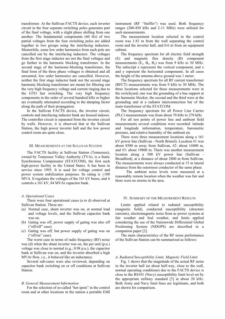
Fig. 1 shows that the magnitude of the actual RF noise in the inverter hall (at about half-way, close to the wall, normal operating conditions) due to the FACTS device is close to the RS101 (Navy) susceptibility limit level set by the appropriate military standard [3] at about 20 kHz. Both Army and Navy limit lines are legitimate, and both are shown for comparison.
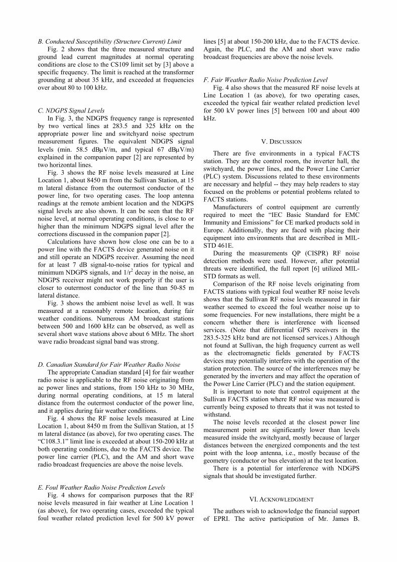
B. Conducted Susceptibility (Structure Current) Limit Fig. 2 shows that the three measured structure and
ground lead current magnitudes at normal operating conditions are close to the CS109 limit set by [3] above a specific frequency. The limit is reached at the transformer grounding at about 35 kHz, and exceeded at frequencies over about 80 to 100 kHz. C. NDGPS Signal Levels
In Fig. 3, the NDGPS frequency range is represented by two vertical lines at 283.5 and 325 kHz on the appropriate power line and switchyard noise spectrum measurement figures. The equivalent NDGPS signal levels (min. 58.5 dBµV/m, and typical 67 dBµV/m) explained in the companion paper [2] are represented by two horizontal lines.
Fig. 3 shows the RF noise levels measured at Line Location 1, about 8450 m from the Sullivan Station, at 15 m lateral distance from the outermost conductor of the power line, for two operating cases. The loop antenna readings at the remote ambient location and the NDGPS signal levels are also shown. It can be seen that the RF noise level, at normal operating conditions, is close to or higher than the minimum NDGPS signal level after the corrections discussed in the companion paper [2].
Calculations have shown how close one can be to a power line with the FACTS device generated noise on it and still operate an NDGPS receiver. Assuming the need for at least 7 dB signal-to-noise ratios for typical and minimum NDGPS signals, and 1/r2 decay in the noise, an NDGPS receiver might not work properly if the user is closer to outermost conductor of the line than 50-85 m lateral distance.
Fig. 3 shows the ambient noise level as well. It was measured at a reasonably remote location, during fair weather conditions. Numerous AM broadcast stations between 500 and 1600 kHz can be observed, as well as several short wave stations above about 6 MHz. The short wave radio broadcast signal band was strong. D. Canadian Standard for Fair Weather Radio Noise
The appropriate Canadian standard [4] for fair weather radio noise is applicable to the RF noise originating from ac power lines and stations, from 150 kHz to 30 MHz, during normal operating conditions, at 15 m lateral distance from the outermost conductor of the power line, and it applies during fair weather conditions.
Fig. 4 shows the RF noise levels measured at Line Location 1, about 8450 m from the Sullivan Station, at 15 m lateral distance (as above), for two operating cases. The “C108.3.1” limit line is exceeded at about 150-200 kHz at both operating conditions, due to the FACTS device. The power line carrier (PLC), and the AM and short wave radio broadcast frequencies are above the noise levels. E. Foul Weather Radio Noise Prediction Levels
Fig. 4 shows for comparison purposes that the RF noise levels measured in fair weather at Line Location 1 (as above), for two operating cases, exceeded the typical foul weather related prediction level for 500 kV power
lines [5] at about 150-200 kHz, due to the FACTS device. Again, the PLC, and the AM and short wave radio broadcast frequencies are above the noise levels. F. Fair Weather Radio Noise Prediction Level
Fig. 4 also shows that the measured RF noise levels at Line Location 1 (as above), for two operating cases, exceeded the typical fair weather related prediction level for 500 kV power lines [5] between 100 and about 400 kHz.
V. DISCUSSION
There are five environments in a typical FACTS station. They are the control room, the inverter hall, the switchyard, the power lines, and the Power Line Carrier (PLC) system. Discussions related to these environments are necessary and helpful -- they may help readers to stay focused on the problems or potential problems related to FACTS stations.
Manufacturers of control equipment are currently required to meet the “IEC Basic Standard for EMC Immunity and Emissions” for CE marked products sold in Europe. Additionally, they are faced with placing their equipment into environments that are described in MIL-STD 461E.
During the measurements QP (CISPR) RF noise detection methods were used. However, after potential threats were identified, the full report [6] utilized MIL-STD formats as well.
Comparison of the RF noise levels originating from FACTS stations with typical foul weather RF noise levels shows that the Sullivan RF noise levels measured in fair weather seemed to exceed the foul weather noise up to some frequencies. For new installations, there might be a concern whether there is interference with licensed services. (Note that differential GPS receivers in the 283.5-325 kHz band are not licensed services.) Although not found at Sullivan, the high frequency current as well as the electromagnetic fields generated by FACTS devices may potentially interfere with the operation of the station protection. The source of the interferences may be generated by the inverters and may affect the operation of the Power Line Carrier (PLC) and the station equipment.
It is important to note that control equipment at the Sullivan FACTS station where RF noise was measured is currently being exposed to threats that it was not tested to withstand.
The noise levels recorded at the closest power line measurement point are significantly lower than levels measured inside the switchyard, mostly because of larger distances between the energized components and the test point with the loop antenna, i.e., mostly because of the geometry (conductor or bus elevation) at the test location.
There is a potential for interference with NDGPS signals that should be investigated further.
VI. ACKNOWLEDGMENT
The authors wish to acknowledge the financial support of EPRI. The active participation of Mr. James B.
Cutshall (TVA) in the preparations of the tests and during the actual measurements at Sullivan was appreciated very much. The assistance of Mr. Daniel Widener (TVA) during the measurements is also acknowledged.
[3] Requirements for the Control of EMI Characteristics of Subsytems and Equipment, MIL-STD-461E, August 1999.
[4] Limits and Measurement Methods of EM Noise from AC Power Systems, 0.15-30 MHz, National Standard of Canada, CAN3-C108.3.1-M84, Canadian Standards Association, May 1984.
[5] Transmission Line Reference Book, 345 kV and Above, Second Edition, EPRI, Palo Alto, California, 1984.
VII. REFERENCES
[1] N. G. Hingorani and L. Gyugyi, Understanding FACTS, IEEE Press, 2000.
[2] R. Olsen et al., Limits Applied to EM Noise Electromagnetic Measurements Near FACTS Devices, Companion Paper, St. Petersburg PowerTech, 2005.
[6] Electromagnetic Interference Emission Measurements Near FACTS Devices, Final Report., No. 1007753, EPRI, Palo Alto, California, 2003.
RFCT on XFMR #2 Ground LeadRFCT on Bus Support Ground LeadRFCT on Radiator Interconnect BarCS-109-1 Limit
Fig. 2. Switchyard, RFCT measurements with CS109 [3] limits.
Sullivan, Line Location #1, 15 meter distance, Loop Antenna
Frequency (MHz)
0.01 0.1 1 10
dBuV
/met
er Q
uasi
-Pea
k - L
oop
Ant
enna
10
30
50
70
90
110
130
NormalOFF/OFFRemote Ambient, E/W
NDGPS Band
Minimum NDGPS Signal
Typical NDGPS Signal
Fig. 3. Sullivan - North Bristol 161 kV line, about 8450 m from Sullivan, 15 m lateral distance, normal and “off/off” cases, loop antenna m urements with NDGPS signal levels corrected for QP 9 kHz BW (CISPR) noise measurements.
eas
Sullivan, Line Location #1, 15 meter distance, Loop Antenna
Fig. 4. Sullivan - North Bristol 161 kV line, about 8450 m from Sullivan, 15 m lateral distance, normal and "off/off" cases, loop antenna easurements with radio noise limit lines.