+ All Categories
Home > Documents > 0456_PDF_02

0456_PDF_02

Date post: 07-Aug-2018
Category:
Upload: luss4u
View: 212 times
Download: 0 times
Share this document with a friend
29
Chapter two Rule-based systems 2.1 Rules and facts A rule-based system is a knowledge-based system where the knowledge base is represented in the form of a set, or sets, of rules. Rules are an elegant, expressive, straightforward, and flexible means of expressing knowledge. The simplest type of rule is called a production rule  and takes the form: IF <condition> THEN <conclusion> An example of a production rule might be: IF the tap is open THEN water flows Part of the attraction of using production rules is that they can often be written in a form that closely resembles natural language, as opposed to a computer language. A simple rule like the one above is intelligible to anyone who understands English. Although rules can be considerably more complex than this, their explicit nature still makes them more intelligible than conventional computer code. In order for rules to be applied, and hence for a rule-based system to be of any use, the system will need to have access to  facts. Facts are unconditional statements which are assumed to be correct at the time that they are used. For example, the tap is open  is a fact. Facts can be: looked up fr om a d at abase; alr ead y stored i n comput er me mor y; determined from sensors connec ted t o the comput er; obtain ed b y pro mpting the user for i nforma tion; derived by applyi ng rul es to other facts. Facts can be thought of as special rules, where the condition part is always true. Therefore, the fact the tap is open could also be thought of as a rule: © 2001 by CRC Press LLC
Transcript

8/20/2019 0456_PDF_02

http://slidepdf.com/reader/full/0456pdf02 1/29

Chapter two

Rule-based systems

2.1 Rules and facts

A rule-based system is a knowledge-based system where the knowledge base is

represented in the form of a set, or sets, of rules. Rules are an elegant,

expressive, straightforward, and flexible means of expressing knowledge. Thesimplest type of rule is called a production rule and takes the form:

IF <condition> THEN <conclusion>

An example of a production rule might be:

IF the tap is open THEN water flows

Part of the attraction of using production rules is that they can often be written

in a form that closely resembles natural language, as opposed to a computer language. A simple rule like the one above is intelligible to anyone who

understands English. Although rules can be considerably more complex than

this, their explicit nature still makes them more intelligible than conventional

computer code.

In order for rules to be applied, and hence for a rule-based system to be of 

any use, the system will need to have access to  facts. Facts are unconditional

statements which are assumed to be correct at the time that they are used. For 

example, the tap is open is a fact. Facts can be:

• looked up from a database;

• already stored in computer memory;

• determined from sensors connected to the computer;

• obtained by prompting the user for information;

• derived by applying rules to other facts.

Facts can be thought of as special rules, where the condition part is always

true. Therefore, the fact the tap is open could also be thought of as a rule:

© 2001 by CRC Press LLC

8/20/2019 0456_PDF_02

http://slidepdf.com/reader/full/0456pdf02 2/29

IF TRUE THEN the tap is open

Given the rule IF the tap is open THEN water flows and the fact the tap

is open, the derived fact water flows  can be generated. The new fact is

stored in computer memory and can be used to satisfy the conditions of other 

rules, thereby leading to further derived facts. The collection of facts which are

known to the system at any given time is called the fact base.Rule-writing is a type of declarative programming (see Section 1.6),

 because rules represent knowledge that can be used by the computer, without

specifying how and when to apply that knowledge. The ordering of rules in a

 program should ideally be unimportant, and it should be possible to add new

rules or modify existing ones without fear of side effects. We will see by

reference to some simple examples that these ideals cannot always be taken for 

granted.

For the declared rules and facts to be useful, an inference engine for 

interpreting and applying them is required (see Section 1.5). Inference enginesare incorporated into a range of software tools, discussed in Chapter 10, that

includes expert system shells, artificial intelligence toolkits, software libraries,

and the Prolog language.

2.2 A rule-based system for boiler control 

Whereas the above discussion describes rule-based systems in an abstract

fashion, a physical example is introduced in this section. We will consider arule-based system to monitor the state of a power station boiler and to advise

appropriate actions. The boiler in our example (Figure 2.1) is used to produce

steam to drive a turbine and generator. Water is heated in the boiler tubes to

 produce a steam and water mixture that rises to the steam drum, which is a

cylindrical vessel mounted horizontally near the top of the boiler. The purpose

of the drum is to separate the steam from the water. Steam is taken from the

drum, passed through the superheater and applied to the turbine that turns the

generator. Sensors are fitted to the drum in order to monitor:

• the temperature of the steam in the drum;

• the voltage output from a transducer, which in turn monitors the level of 

water in the drum;

• the status of pressure release valve (i.e., open or closed);

• the rate of flow of water through the control valve.

The following rules have been written for controlling the boiler:

© 2001 by CRC Press LLC

8/20/2019 0456_PDF_02

http://slidepdf.com/reader/full/0456pdf02 3/29

/* Rule 2.1 */

IF water level low THEN open control valve

/* Rule 2.2 */

IF temperature high AND water level low

THEN open control valve AND shut down boiler tubes

/* Rule 2.3 */

IF steam outlet blocked THEN replace outlet pipe

/* Rule 2.4 */IF release valve stuck THEN steam outlet blocked

/* Rule 2.5 */

IF pressure high AND release valve closed

THEN release valve stuck

/* Rule 2.6 */

IF steam escaping THEN steam outlet blocked

float and transducer 

 pressure releasevalve

steamdrum

steam

water 

steam

steamsuperheater 

superheated steam to turbine

steamoutlet pipe

steam and water 

 boiler tubes

controlvalve

condensatefrom turbine

  water 

thermometer 

Figure 2.1  A power station boiler 

© 2001 by CRC Press LLC

8/20/2019 0456_PDF_02

http://slidepdf.com/reader/full/0456pdf02 4/29

/* Rule 2.7 */

IF temperature high AND NOT(water level low)

THEN pressure high

/* Rule 2.8 */

IF transducer output low THEN water level low

/* Rule 2.9 */IF release valve open AND flow rate high

THEN steam escaping

/* Rule 2.10 */

IF flow rate low THEN control valve closed

The conclusions of three of the above rules (2.1, 2.2, and 2.3) consist of 

recommendations to the boiler operators. In a fully automated system, such

rules would be able to perform their recommended actions rather than simply

making a recommendation. The remaining rules all involve taking a low-levelfact, such as a transducer reading, and deriving a higher-level fact, such as the

quantity of water in the drum. The input data to the system (sensor readings in

our example) are low-level facts; higher-level facts are facts derived from

them.

Most of the rules in our rule base are specific to one particular boiler 

arrangement and would not apply to other situations. These rules could be

described as shallow, because they represent shallow knowledge. On the other 

hand, Rule 2.7 expresses a fundamental rule of physics, namely that the boiling

temperature of a liquid increases with increasing applied pressure. This is validunder any circumstances and is not specific to the boiler shown in Figure 2.1.

It is an example of a deep rule expressing deep knowledge.

The distinction between deep and shallow rules should not be confused

with the distinction between high-level  and low-level  rules. Low-level rules are

those that depend on low-level facts. Rule 2.8 is a low-level rule since it is

dependent on a transducer reading. High-level rules make use of more abstract

information, such as Rule 2.3 which relates the occurrence of a steam outlet

 blockage to a recommendation to replace a pipe. Higher-level rules are those

which are closest to providing a solution to a problem, while lower-level rulesrepresent the first stages toward reaching a conclusion.

2.3 Rule examination and rule firing 

In Section 2.2, a rule base for boiler control was described without mention of 

how the rules would be applied. The task of interpreting and applying the rules

© 2001 by CRC Press LLC

8/20/2019 0456_PDF_02

http://slidepdf.com/reader/full/0456pdf02 5/29

 belongs to the inference engine (see Chapter 1). The application of rules can be

 broken down as follows:

(i) selecting rules to examine — these are the available rules;

(ii) determining which of these are applicable — these are the triggered  rules;

they make up the conflict set ;

(iii) selecting a rule to fire (described below).

The distinction between examination and firing of rules is best explained by

example. Suppose the rule-based system has access to the transducer output

and to the temperature readings. A sensible set of rules to examine would be

2.2, 2.7, and 2.8, as these rules are conditional on the boiler temperature and

transducer output. If the transducer level is found to be low, then Rule 2.8 is

applicable. If it is selected and used to make the deduction water level low,

then the rule is said to have  fired . If the rule is examined but cannot fire

(because the transducer reading is not low), the rule is said to fail .

The condition part of Rule 2.2 can be satisfied only if Rule 2.8 has been

fired. For this reason, it makes sense to examine Rule 2.8 before Rule 2.2. If 

Rule 2.8 fails, then Rule 2.2 need not be examined as it too will fail. The inter-

dependence between rules is discussed further in Sections 2.4 and 2.5.

The method for rule examination and firing described so far is a form of 

forward-chaining. This strategy and others are discussed in more detail in

Sections 2.7 through 2.10.

2.4 Maintaining consistency 

A key advantage of rule-based systems is their flexibility. New rules can be

added at will, but only if each rule is written with care and without assuming

the behavior of other rules. Consider Rule 2.4:

/* Rule 2.4 */

IF release valve stuck THEN steam outlet blocked

Given the current rule base, the fact release valve stuck  could only be

established by first firing Rule 2.5:

/* Rule 2.5 */

IF pressure high AND release valve closed

THEN release valve stuck

Rule 2.5 is sensible, since the purpose of the release valve is to open itself 

automatically if the pressure becomes high, thereby releasing the excess

© 2001 by CRC Press LLC

8/20/2019 0456_PDF_02

http://slidepdf.com/reader/full/0456pdf02 6/29

 pressure. Rule 2.4, however, is less sensible. The fact release valve stuck

is not in itself sufficient evidence to deduce that the steam outlet is blocked.

The other necessary evidence is that the pressure in the drum must be high.

The reason that the rule base works in its current form is that in order for the

system to believe the release valve to be stuck, the pressure must   be high.

Although the rule base works, it is not robust and is not tolerant of new

knowledge being added. Consider, for instance, the effect of adding the

following rule:

/* Rule 2.11 */

IF pressure low AND release valve open THEN release valve stuck

This rule is in itself sensible. However, the addition of the rule has an

unwanted effect on Rule 2.4. Because of the unintended interaction between

Rules 2.4 and 2.11, low pressure in the drum and the observation that the

release valve is open result in the erroneous conclusion that the steam outlet is blocked. Problems of this sort can be avoided by making each rule an accurate

statement in its own right. Thus in our example, Rule 2.4 should be written as:

/* Rule 2.4a */

IF pressure high AND release valve stuck

THEN steam outlet blocked

A typical rule firing order, given that the drum pressure is high and the release

valve closed, might be:

/* Rule 2.5 */

IF pressure high AND release valve closed

THEN release valve stuck

/* Rule 2.4a */

IF pressure high AND release valve stuck

THEN steam outlet blocked

/* Rule 2.3 */IF steam outlet blocked THEN replace outlet pipe

The modification that has been introduced in Rule 2.4a means that the

conditions of both Rules 2.5 and 2.4a involve checking to see whether the

drum pressure is high. This source of inefficiency can be justified through the

improved robustness of the rule base. In fact, the Rete algorithm, described in

Section 2.7.2, allows rule conditions to be duplicated in this way with minimal

loss of efficiency.

© 2001 by CRC Press LLC

8/20/2019 0456_PDF_02

http://slidepdf.com/reader/full/0456pdf02 7/29

In general, rules can be considerably more complex than the ones we have

considered so far. For instance, rules can contain combinations of conditions

and conclusions, exemplified by combining Rules 2.3, 2.4, and 2.6  to form a

new rule:

/* Rule 2.12 */

IF (pressure high AND release valve stuck) OR steam escapingTHEN steam outlet blocked AND outlet pipe needs replacing

2.5 The closed-world assumption

If we do not know that a given proposition is true, then in many rule-based

systems the proposition is assumed to be false. This assumption, known as the

closed-world assumption, simplifies the logic required as all propositions are

either TRUE or FALSE. If the closed-world assumption is not made, then a

third category, namely UNKNOWN, has to be introduced. To illustrate the

closed-world assumption, let us return to the boiler control example. If steam

outlet blocked  is not known, then NOT (steam outlet blocked)  is

assumed to be true. Similarly if water level low  is not known, then NOT

(water level low)  is assumed to be true. The latter example of the closed-

world assumption affects the interaction between Rules 2.7 and 2.8:

/* Rule 2.7 */

IF temperature high AND NOT(water level low) THEN pressure high

/* Rule 2.8 */

IF transducer output low THEN water level low

Consider the case where the temperature reading is high and the

transducer output is low. Whether or not the pressure is assumed to be high

will depend on the order in which the rules are selected for firing. If we fire

Rule 2.7 followed by 2.8, the following deductions will be made:

temperature high — TRUE 

NOT(water level low) — TRUE by closed-world assumption

therefore 

pressure is high (Rule 2.7)

transducer output low — TRUE 

therefore water level low (Rule 2.8)

Alternatively, we could examine Rule 2.8 first:

© 2001 by CRC Press LLC

8/20/2019 0456_PDF_02

http://slidepdf.com/reader/full/0456pdf02 8/29

transducer output low — TRUE 

therefore water level low (Rule 2.8)

temperature high — TRUE 

NOT(water level low) — FALSE 

 Rule 2.7 fails

It is most likely that the second outcome was intended by the rule-writer. There

are two measures that could be taken to avoid this ambiguity, namely, to

modify the rules or to modify the inference engine. The latter approach would

aim to ensure that Rule 2.8 is examined before 2.7, and a method for achieving

this is described in Section 2.10. The former solution could be achieved by

altering the rules so that they do not contain any negative conditions, as shown

 below:

/* Rule 2.7a */IF temperature high AND water level not_low THEN pressure high

/* Rule 2.8 */

IF transducer output low THEN water level low

/* Rule 2.8a */

IF transducer output not_low THEN water level not_low

2.6 Use of variables within rules

The boiler shown in Figure 2.1 is a simplified view of a real system, and the

accompanying rule set is much smaller than those associated with most real-

world problems. In real-world systems, variables can be used to make rules

more general, thereby reducing the number of rules needed and keeping the

rule set manageable. The sort of rule that is often required is of the form:

For all x, IF <condition about x> THEN <conclusion about x>

To illustrate this idea, let us imagine a more complex boiler. This boiler may,

for instance, have many water supply pipes, each with its own control valve.

For each pipe, the flow rate will be related to whether or not the control valve

is open. So some possible rules might be of the form:

/* Rule 2.13 */

IF control valve 1 is open THEN flow rate in tube 1 is high

© 2001 by CRC Press LLC

8/20/2019 0456_PDF_02

http://slidepdf.com/reader/full/0456pdf02 9/29

/* Rule 2.14 */

IF control valve 2 is open THEN flow rate in tube 2 is high

/* Rule 2.15 */

IF control valve 3 is open THEN flow rate in tube 3 is high

/* Rule 2.16 */

IF control valve 4 is open THEN flow rate in tube 4 is high

/* Rule 2.17 */

IF control valve 5 is open THEN flow rate in tube 5 is high

A much more compact, elegant and flexible representation of these rules would

 be:

/* Rule 2.18 */

IF control valve ?x is open THEN flow rate in tube ?x is high

Here we have used a question mark (‘?’) to denote that x is a variable. Now if 

the sensors detect that any control valve is open, the identity of the control

valve is substituted for x when the rule is fired. The variable x  is said to be

instantiated  with a value, in this case an identity number. Thus, if control valve

3 is open, x  is instantiated with the value 3 and the deduction flow rate in

tube 3 is high is made.

In this example the possible values of x were limited, and so the use of a

variable was convenient rather than necessary. Where the possible values of a

variable cannot be anticipated in advance, the use of variables becomes

essential. This is the case when values are being looked up, perhaps from a

database or from a sensor. As an example, consider the following rule:

/* Rule 2.19 */

IF (drum pressure is ?p) AND (?p > threshold) THEN

tube pressure is (?p/10)

Without the use of the variable name p, it would not be possible to generate a

derived fact which states explicitly a pressure value. Suppose that the drum pressure sensor is reading a value of 300MNm2 and threshold  is a variable

currently set to 100MNm2

. Rule 2.19 can therefore be fired, and the derived

fact tube pressure is 30 (MNm2)  is generated. Note that in this example

the value of the variable p  has been manipulated, i.e., divided by 10. More

sophisticated rule-based systems allow values represented as variables to be

manipulated in this way or passed as parameters to procedures and functions.

The association of a specific value (say, 300MNm2) with a variable name

(such as p) is sometimes referred to as unification. The term applies not only to

© 2001 by CRC Press LLC

8/20/2019 0456_PDF_02

http://slidepdf.com/reader/full/0456pdf02 10/29

numerical examples but to any form of data. The word arises because, from the

computer’s perspective, the following are contradictory pieces of information:

pressure is p;

pressure is 300 (units of MNm2 assumed).

This conflict can be resolved by recognizing that one of the values is a variable

name (because in our syntax it is preceded by a question mark) and by making

the following assignment or unification:

p:=300

The use of variable names within rules is integral to the Prolog language

(see Chapter 10). In Prolog, rather than using a question mark, variables are

distinguished from constants by having an underscore or upper case letter as

their first character. Other languages would require the user to program this

facility or to purchase suitable software.

2.7 Forward-chaining (a data-driven strategy)

As noted in Section 2.3, the inference engine applies a strategy for deciding

which rules to apply and when to apply them. Forward-chaining is the name

given to a data-driven strategy, i.e., rules are selected and applied in response

to the current fact base. The fact base comprises all facts known by the system,

whether derived by rules or supplied directly (see Section 2.1).

A schematic representation of the cyclic selection, examination and firing

of rules is shown in Figure 2.2. The cycle of events shown in Figure 2.2 is just

one version of forward-chaining, and variations in the strategy are possible.

The key points of the scheme shown in Figure 2.2 are as follows:

• rules are examined and fired on the basis of the current fact base,

independently of any predetermined goals;

• the set of rules available for examination may comprise all  of the rules or 

a subset;

• of the available rules, those whose conditions are satisfied are said to have

 been triggered . These rules make up the conflict set , and the method of 

selecting a rule from the conflict set is conflict resolution (Section 2.8);

© 2001 by CRC Press LLC

:

8/20/2019 0456_PDF_02

http://slidepdf.com/reader/full/0456pdf02 11/29

• although the conflict set may contain many rules, only one rule is fired on

a given cycle. This is because once a rule has fired, the stored deductions

have potentially changed, and so it cannot be guaranteed that the other 

rules in the conflict set still have their condition parts satisfied.

Select rules to examine

(often all rules are selected)

Select a rule from the conflict set(conflict resolution) and fire it

Conflict set

empty?

Evaluate condition part of first rule

Condition met?

Add rule to conflict set

Any more rules

to examine?

Stop

Start

Evaluate condition part

 of next rule

 yes

no

 yesno

no

 yes

Empty the conflict set

Figure 2.2  Forward-chaining

© 2001 by CRC Press LLC

8/20/2019 0456_PDF_02

http://slidepdf.com/reader/full/0456pdf02 12/29

2.7.1 Single and multiple instantiation of variables

As noted above, variations on the basic scheme for forward-chaining are

 possible. Where variables are used in rules, the conclusions may be performed

using just the first set of instantiations that are found — this is singleinstantiation. Alternatively, the conclusions may be performed repeatedly

using all possible instantiations — this is multiple instantiation. The difference

 between the two approaches is shown in Figure 2.3. As an example, consider 

the following pair of rules:

/* Rule 2.20 */

IF control valve ?x is open THEN flow rate in tube ?x is high

Find all sets of instantiations

of variables

Fire conclusion for each set of 

instantiations

Build conflict set

Select rule to fire

Find one set of instantiations

of variables

Fire conclusion for that set of 

instantiations

Build conflict set

Select rule to fire

Conflict set

empty?Stop

no

 yes

Conflict set

empty?Stop

no

 yes

(a) (b)

Figure 2.3 Alternative forms of forward-chaining:(a) multiple instantiation of variables

(b) single instantiation of variables

© 2001 by CRC Press LLC

8/20/2019 0456_PDF_02

http://slidepdf.com/reader/full/0456pdf02 13/29

/* Rule 2.21 */

IF flow rate in tube ?x is high THEN close control valve ?x

Suppose that we start with two facts:

control valve 1 is opencontrol valve 2 is open

Under multiple instantiation, each rule would fire once, generating conclusions

in the following order:

flow rate in tube 1 is high

flow rate in tube 2 is high

close control valve 1

close control valve 2

If the conflict resolution strategy gives preference to Rule 2.21 over Rule 2.20,

a different firing order would occur under single instantiation. Each cycle of 

the inference engine would result in a rule firing on a single instantiation of the

variable x. After four cycles, conclusions would have been generated in the

following order:

flow rate in tube 1 is high

close control valve 1

close control

valve 2

flow rate in

tube 1 is high

close control

valve 1

flow rate in

tube 2 is high

close control

valve 2

flow rate in

tube 1 is high

close control

valve 1

flow rate in

tube 2 is high

(a) (b)

Figure 2.4   Applying Rules 2.20 and 2.21:(a) multiple instantiation is a breadth-first process

(b) single instantiation is a depth-first process

© 2001 by CRC Press LLC

8/20/2019 0456_PDF_02

http://slidepdf.com/reader/full/0456pdf02 14/29

flow rate in tube 2 is high

close control valve 2

Multiple instantiation is a breadth-first approach to problem solving and single

instantiation is a depth-first approach, as illustrated in Figure 2.4. The practical

implications of the two approaches are discussed in Chapters 11 and 14.

2.7.2 Rete algorithm

The scheme for forward-chaining shown in Figure 2.2  contains at least one

source of inefficiency. Once a rule has been selected from the conflict set and

fired, the conflict set is thrown away and the process starts all over again. This

is because firing a rule alters the fact base, so that a different set of rules may

qualify for the conflict set. A new conflict set is therefore drawn up by re-

examining the condition parts of all the available rules. In most applications,

the firing of a single rule makes only slight changes to the fact base and henceto the membership of the conflict set. Therefore, a more efficient approach

would be to examine only those rules whose condition is affected by changes

made to the fact base on the previous cycle. The Rete (pronounced “ree-tee”)

algorithm [1, 2] is one way of achieving this.

The principle of the Rete algorithm can be shown by a simple example,

using the following rule:

/* Rule 2.22*/

IF ?p is a pipe of bore ?b AND ?v is a valve of bore ?b

THEN ?p and ?v are compatible

Prior to running the system, the condition parts of all the rules are assembled

into a Rete network , where each node represents an atomic condition, i.e., one

that contains a simple test. There are two types of nodes — alpha nodes can be

satisfied by a single fact, whereas beta nodes can only be satisfied by a pair of 

facts. The condition part of Rule 2.22 would be broken down into two alpha

nodes and one beta node:

1: find a pipe2: find a valve

1: the bore of each must be equal

The Rete network for this example is shown in Figure 2.5.  Suppose that,

initially, the only relevant fact is:

p1 is a pipe of bore 100mm

© 2001 by CRC Press LLC

8/20/2019 0456_PDF_02

http://slidepdf.com/reader/full/0456pdf02 15/29

 Node 1 would be satisfied, and so the fact would be passed on to node 1.

However, node 1 would not be satisfied as it has received no information

from node 2. The fact that there is a pipe of bore 100mm would remain stored

at node 1. Imagine now that, as a result of firing other rules, the following

fact is derived:

v1 is a valve of bore 100mm

This fact satisfies node 2 and is passed on to node 1. Node 1 is satisfied by

the combination of the new fact and the one that was already stored there.

Thus, Rule 2.22 can be added to the conflict set without having to find a pipe

again (the task of node 1).

A full Rete network would contain nodes representing the subconditions

of all the rules in the rule base. Every time a rule is fired, the altered facts

would be fed into the network and the changes to the conflict set generated.

Where rules contain identical subconditions, nodes can be shared, thereby

avoiding duplicated testing of the conditions. In an evaluation of some

commercially available artificial intelligence toolkits that use forward-

chaining, those that incorporated the Rete algorithm were found to offer 

substantial improvements in performance [3].

α1:

find a pipe

α2:

find a valve

β1:each item has the same bore

new facts

The rule is added to the conflict set 

if a fact passes node β1

Figure 2.5  A Rete network for Rule 2.22

© 2001 by CRC Press LLC

8/20/2019 0456_PDF_02

http://slidepdf.com/reader/full/0456pdf02 16/29

2.8 Conflict resolution

2.8.1 First come, first served 

As noted above, conflict resolution is the method of choosing one rule to fire

from those that are able to fire, i.e., from the set of triggered rules, known as

the conflict set. In Figure 2.2,  the complete conflict set is found beforechoosing a rule to fire. Since only one rule from the conflict set can actually

fire on a given cycle, the time spent evaluating the condition parts of the other 

rules is wasted unless the result is saved by using a Rete algorithm or similar 

technique. A strategy which overcomes this inefficiency is to fire immediately

the first rule to be found that qualifies for the conflict set (Figure 2.6). In this

scheme, the conflict set is not assembled at all, and the order in which rules are

selected for examination determines the resolution of conflict. The order of 

rule examination is often simply the order in which the rules appear in the rule

 base. If the rule-writer is aware of this, the rules can be ordered in accordancewith their perceived priority.

2.8.2 Priority values

Rather than relying on rule ordering as a means of determining rule priorities,

rules can be written so that each has an explicitly stated priority value. Where

more than one rule is able to fire, the one chosen is the one having the highest

 priority. The two rules below would be available for firing if the water level

had been found to be low (i.e., Rule 2.8 had fired) and if the temperature werehigh:

/* Rule 2.1a */

IF water level low THEN open control valve PRIORITY 4.0

/* Rule 2.2a */

IF temperature high and water level low THEN

open control valve AND shut down boiler tubes PRIORITY 9.0

In the scheme shown here, Rule 2.2a would be selected for firing as it has the

higher priority value. This scheme arbitrarily uses a scale of priorities from 1

to 10.

As the examination of rules that are not fired represents wasted effort, an

efficient use of priorities would be to select rules for examination in order of 

their priority. Once a rule has been found which is fireable, it could be fired

immediately. This scheme is identical to the “first come, first served” strategy

(Figure 2.6), except that rules are selected for examination according to their 

 priority value rather than their position in the rule base.

© 2001 by CRC Press LLC

8/20/2019 0456_PDF_02

http://slidepdf.com/reader/full/0456pdf02 17/29

2.8.3 Metarules

Metarules are rules which are not specifically concerned with knowledge about

the application at hand, but rather with knowledge about how that knowledge

should be applied. Metarules are therefore “rules about rules” (or more

generally, “rules about knowledge”). Some examples of metarules might be:

/* Metarule 2.23 */

PREFER rules about shut-down TO rules about control valves

Select rules to examine

(often all rules are selected)

Evaluate condition part of first rule

Condition met?

Fire the rule

Any more rules

to examine?

Stop

Start

Evaluate condition part

 of next rule

 yes

no

 yes

no

Figure 2.6   Forward-chaining with “first come, first served” conflict resolution

© 2001 by CRC Press LLC

8/20/2019 0456_PDF_02

http://slidepdf.com/reader/full/0456pdf02 18/29

/* Metarule 2.24 */

PREFER high-level rules TO low-level rules

If Rules 2.1 and 2.2 are both in the conflict set, Metarule 2.23 will be fired,

with the result that Rule 2.2 is then fired. If a conflict arises for which no

metarule can be applied, then a default method such as “first come, first

served” can be used.

2.9 Backward-chaining (a goal-driven strategy)

2.9.1 The backward-chaining mechanism

Backward-chaining is an inference strategy that assumes the existence of a

goal that needs to be established or refuted. In the boiler control example, our 

goal might be to establish whether it is appropriate to replace the outlet pipe,

and we may not be interested in any other deductions that the system is capable

of making. Backward-chaining provides the means for achieving this. Initially,

only those rules that can lead directly to the fulfillment of the goal are selectedfor examination. In our case, the only rule that can achieve the goal is Rule 2.3,

since it is the only rule whose conclusion is replace outlet pipe. The

condition part of Rule 2.3 is examined but, since there is no information about

a steam outlet blockage in the fact base, Rule 2.3 cannot be fired yet. A new

goal is then produced, namely steam outlet blocked, corresponding to the

condition part of Rule 2.3. Two rules, 2.4 and 2.6, are capable of fulfilling this

goal and are therefore antecedents of Rule 2.3. What happens next depends on

whether a depth-first or breadth-first search strategy is used. These two

methods for exploring a search tree were introduced in Chapter 1, but now the

nodes of the search tree are rules.

For the moment we will assume the use of a depth-first search strategy, as

this is normally adopted. The use of a breadth-first search is discussed in

Section 2.9.3. One of the two relevant rules (2.4 or 2.6) is selected for 

examination. Let us suppose that Rule 2.6 is chosen. Rule 2.6 can fire only if 

steam is escaping from the drum. This information is not in the fact base, so

steam escaping becomes the new goal. The system searches the rule base for 

a rule which can satisfy this goal. Rule 2.9 can satisfy the goal, if its conditionis met. The condition part of Rule 2.9 relies only on the status of the release

valve. If the valve were found to be open, then 2.9 would be able to fire, the

goal steam escaping  could be satisfied, Rule 2.6 would be fireable and the

original goal thus fulfilled.

8/20/2019 0456_PDF_02

http://slidepdf.com/reader/full/0456pdf02 19/29

Let us suppose, on the other hand, that the release valve is found to be

closed. Rule 2.9 therefore fails, with the result that Rule 2.6 also fails. The

system backtracks to the last place where a choice between possible rules was

made and will try an alternative, as shown in Figure 2.7. In the example shown

here, this means that Rule 2.4 is examined next. It can fire only if the release

valve is stuck but, because this information is not yet known, it becomes the

new goal. This process continues until a goal is satisfied by the information in

the fact base. When this happens, the original goal is fulfilled, and the chosen

 path through the rules is the solution. If all possible ways of achieving the

overall goal have been explored and failed, then the overall goal fails.

The backward-chaining mechanism described so far has assumed a depth-

first search for rules. This means that whenever a choice between rules exists,

 just one is selected, the others being examined only if backtracking occurs.

The inference mechanism built into the Prolog language (see Chapter 10)

is a depth-first backward-chainer, like that described here. There are two sets

of circumstances under which backtracking takes place:

Rule 2.3

Rule 2.4

Rule 2.5

Rule 2.7

Goal: replace

outlet pipe

search

Failure

Rule 2.6

Rule 2.9

search

Success

backtrack 

Figure 2.7  Backward-chaining applied to the boiler control rules:

the search for rules proceeds in a depth-first manner 

© 2001 by CRC Press LLC

8/20/2019 0456_PDF_02

http://slidepdf.com/reader/full/0456pdf02 20/29

Start

Goal G1 satisfied?

Goal is G1

Rule X1exists that satisfies

G1?

Condition part of rule X1 is goal G2

Another solution

wanted?

Stop

      B    a    c      k     t    r    a    c      k

Backtrack 

Choose new rule X1

Stop

Success

Goal failed

 yes

no

 yes

no

 yes

no

      B    a    c      k     t    r    a    c      k

etc

Goal G2 satisfied?

Goal is G2

Rule X2exists that satisfies

G2?

Condition part of rule X2 is goal G3

Another solution

wanted?

Stop

Backtrack 

Choose new rule X2

Success

 yes

no

 yes

no

 yes

no

Goal G3 satisfied?

Goal is G3

Rule X3exists that satisfies

G3?

Condition part of rule X3 is goal G4

Another solution

wanted?

StopBacktrack 

Choose new rule X3

Success

 yes

no

 yes

no

 yes

no

      B    a    c      k     t    r    a    c      k

etc

Figure 2.8  A flowchart for backward-chaining

© 2001 by CRC Press LLC

8/20/2019 0456_PDF_02

http://slidepdf.com/reader/full/0456pdf02 21/29

(i) when a goal cannot be satisfied by the set of rules currently under 

consideration; or 

(ii) when a goal has been satisfied and the user wants to investigate other 

ways of achieving the goal (i.e., to find other solutions).

2.9.2 Implementation of backward-chaining Figure 2.8 shows a generalized flowchart for backward-chaining from a goal

G1. In order to simplify the chart, it has been assumed that each rule has only

one condition, so that the satisfaction of a condition can be represented as a

single goal. In general, rules have more than one condition. The flowchart in

Figure 2.8 is an attempt to represent backward-chaining as an iterative process.

This is difficult to achieve, as the length of the chain of rules cannot be

 predetermined. The flowchart has, of necessity, been left incomplete. The

flowchart contains repeating sections that are identical except for the variable

names, an indication that while it is difficult to represent the processiteratively, it can be elegantly represented recursively. A recursive definition of 

a function is one that includes the function itself. Recursion is an important

aspect of the artificial intelligence languages Lisp and Prolog, discussed in

Chapter 10, as well as many other computer languages. Box 2.1  shows a

recursive definition of backward-chaining, where it has again been assumed

that rules have only one condition. It is not always necessary to write such a

function for yourself as backward-chaining forms an integral part of the Prolog

language and most expert system shells and artificial intelligence toolkits (see

Chapter 10).

2.9.3 Variations of backward-chaining 

There are a number of possible variations to the idea of backward-chaining.

Some of these are:

(i) depth-first or breadth-first search for rules;

(ii) whether or not to pursue other solutions (i.e., other means of achieving the

goal) once a solution has been found;(iii) different ways of choosing between branches to explore (depth-first search

only);

(iv) deciding upon the order in which to examine rules (breadth-first search

only);

(v) having found a succession of enabling rules whose lowest-level conditions

are satisfied, whether to fire the sequence of rules or simply to conclude

that the goal is proven.

© 2001 by CRC Press LLC

8/20/2019 0456_PDF_02

http://slidepdf.com/reader/full/0456pdf02 22/29

Breadth-first backward-chaining is identical to depth-first, except for the

mechanism for deciding between alternative rules to examine. In the example

described in Section 2.9.1 (and in Figure 2.7), instead of choosing to explore

either 2.4 or 2.6, both rules would be examined. Then the preconditions of each

(i.e., Rules 2.5 and 2.9)  would be examined. If either branch fails, then the

system will not need to backtrack, as it will simply carry on down those

 branches which still have the potential to fulfill the goal. The process is

illustrated in Figure 2.9. The first solution to be found will be the one with the

shortest (or joint-shortest) chain of rules. A disadvantage with the breadth-first

approach is that large amounts of computer memory may be required, as the

system needs to keep a record of progress along all branches of the search tree,

rather than just one branch.

define function backwardchain(G);

/* returns a boolean (i.e., true/false) value */ 

/* G is the goal being validated */ 

variable S, X, C;

result:= false;

/* ‘:=‘ represents assignment of a value to a variable */ 

S:= set of rules whose conclusion part matches goal G;if S is empty then

result:= false;

else

while (result=false) and (S is not empty) do

X:= rule selected from S;

S:= S with X removed;

C:= condition part of X;

if C is true then

result:=true

elseif C is false then

result:=falseelseif (backwardchain(C)=true) then

result:=true;

/* note the recursive call of ‘backwardchain’ */ 

/* C is the new goal */ 

endif;

endwhile;

endif;

return result;

/* ‘result’ is the value returned by the function */ 

/* ‘backwardchain’ */ 

enddefine;

 Box 2.1  A recursive definition of backward-chaining

© 2001 by CRC Press LLC

8/20/2019 0456_PDF_02

http://slidepdf.com/reader/full/0456pdf02 23/29

The last item (v) in the above list of variations of backward-chaining is

important but subtle. So far our discussion of backward-chaining has made

limited reference to rule firing. If a goal is capable of being satisfied by a

succession of rules, the first of which is fireable, then the goal is assumed to be

true and no rules are actually fired . If all that is required is validation of a goal,

then this approach is adequate. However, by actually firing the rules, all of the

intermediate deductions such as water level low  are recorded in the fact

 base and may be used by other rules, thereby eliminating the need to re-

establish them. Therefore, in some implementations of backward-chaining,

once the path to a goal has been established, rules are fired until the original

goal is fulfilled. In more complex rule-based systems, rules may call up and

run a procedurally coded module as part of their conclusion. In such systems,

the firing of the rules is essential for the role of the procedural code to be

realized.

Rule 2.3

Rule 2.4

Rule 2.5

Rule 2.7

Goal: replace

outlet pipe

search

 failure

Rule 2.6

Rule 2.9

success

Figure 2.9 A variation of backward-chaining applied to the boiler control rules;here the search for rules proceeds in a breadth-first manner 

© 2001 by CRC Press LLC

8/20/2019 0456_PDF_02

http://slidepdf.com/reader/full/0456pdf02 24/29

Finally, it should be noted that in some backward-chaining systems the

rule syntax is reversed, compared with the examples that we have discussed so

far. A possible syntax would be:

DEDUCE <conclusion> IF <condition>

The placing of the conclusion before the condition reflects the fact that in backward-chaining systems it is the conclusion part of a rule that is assessed

first, and only if the conclusion is relevant is the condition examined.

2.10 A hybrid strategy 

A system called ARBS (Algorithmic and Rule-based Blackboard System),

described in Chapters 11 and 14, makes use of an inference engine that can be

thought of as part forward-chaining and part backward-chaining [4].Conventional backward-chaining involves initial examination of a rule that

achieves the goal. If that cannot fire, its antecedent rules are recursively

examined, until rules can be fired and progress made toward the goal. In all

 problems involving data interpretation (such as the boiler control example), the

high-level rules concerning the goal itself can never fire until lower-level rules

for data manipulation have been fired. The standard mechanisms for forward-

or backward-chaining, therefore, involve a great deal of redundant rule

examination. The hybrid strategy is a means of eliminating this source of 

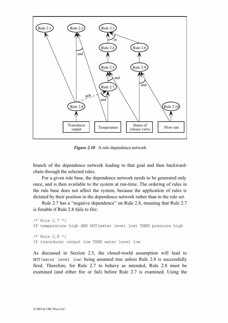
inefficiency.Under the hybrid strategy, a rule dependence network   is built prior to

running the system. For each rule, the network shows which other rules may

enable it, i.e., its antecedents, and which rules it may enable, i.e., its

dependents. The rule dependencies for the boiler control knowledge base are

shown in Figure 2.10.  In its data-driven mode, known as directed forward-

chaining , the hybrid strategy achieves improved efficiency by using the

dependence network to select rules for examination. Low-level rules

concerning the sensor data are initially selected for examination. As shown in

Figure 2.10,  only Rules 2.8, 2.9, and 2.10 need be examined initially. Thenhigher-level rules, leading toward a solution, are selected depending on which

rules have actually fired. So, if Rules 2.8 and 2.9 fire successfully, the new set

of rules to be examined becomes 2.1, 2.2, and 2.6. The technique is an

effective way of carrying out the instruction marked “select rules to examine”

in the flowchart for forward-chaining (Figure 2.2).

The same mechanism can easily be adapted to provide an efficient goal-

driven strategy. Given a particular goal, the control mechanism can select the

© 2001 by CRC Press LLC

8/20/2019 0456_PDF_02

http://slidepdf.com/reader/full/0456pdf02 25/29

 branch of the dependence network leading to that goal and then backward-

chain through the selected rules.

For a given rule base, the dependence network needs to be generated only

once, and is then available to the system at run-time. The ordering of rules in

the rule base does not affect the system, because the application of rules is

dictated by their position in the dependence network rather than in the rule set.

Rule 2.7 has a “negative dependence” on Rule 2.8, meaning that Rule 2.7

is fireable if Rule 2.8 fails to fire:

/* Rule 2.7 */

IF temperature high AND NOT(water level low) THEN pressure high

/* Rule 2.8 */

IF transducer output low THEN water level low

As discussed in Section 2.5, the closed-world assumption will lead to

NOT(water level low)  being assumed true unless Rule 2.8 is successfully

fired. Therefore, for Rule 2.7 to behave as intended, Rule 2.8 must be

examined (and either fire or fail) before Rule 2.7 is examined. Using the

Transduceroutput

Temperature

or

Status of release valve

Rule 2.1 Rule 2.2 Rule 2.3

Rule 2.4 Rule 2.6

Rule 2.5

Rule 2.7

Rule 2.8

and

and

and

Rule 2.9

Rule 2.10

Flow rate

and

 n o t

Figure 2.10  A rule dependence network 

© 2001 by CRC Press LLC

8/20/2019 0456_PDF_02

http://slidepdf.com/reader/full/0456pdf02 26/29

dependence network to direct rule examination and firing is one way of 

ensuring this order of events.

The use of dependence networks is more complicated when variables are

used within rules because the dependencies between rules are less certain.

Consider, for example, the following set of rules that do not  use variables:

/* Rule 2.25 */IF control valve 1 is open AND pipe 1 is blocked

THEN open release valve

/* Rule 2.26 */

IF flow rate through pipe 1 is high

THEN control valve 1 is open

/* Rule 2.27 */

IF pressure in pipe 1 is high

THEN pipe 1 is blocked

A dependence network would show that Rule 2.25 is dependent only on Rules

2.26 and 2.27. Therefore, if 2.26 and 2.27 have fired, 2.25 can definitely fire.

 Now consider the same rules modified to incorporate the use of variables:

/* Rule 2.25a */

IF control valve ?x open AND pipe ?x blocked

THEN open release valve

/* Rule 2.26a */

IF flow rate through pipe ?x is highTHEN control valve ?x open

/* Rule 2.27a */

IF pressure in pipe ?x is high

THEN pipe ?x is blocked

Rule 2.25a is dependent on Rules 2.26a and 2.27a. However, it is possible for 

Rules 2.26a and 2.27a to have fired, but for Rule 2.25a to fail. This is because

the condition of Rule 2.25a requires the valve and pipe numbers (represented

 by x) to be identical, whereas Rules 2.26a and 2.27a could each use a different

value for x. Thus when rules contain variables, a dependence network shows

which rules have the  potential   to enable others to fire. Whether or not the

dependent rules will actually fire cannot be determined until run-time. The

dependence network shows us that Rule 2.25a should be examined if Rules

2.26a and 2.27a have fired, but otherwise it can be ignored.

A similar situation arises when there is a negative dependence between

rules containing variables, for example:

© 2001 by CRC Press LLC

8/20/2019 0456_PDF_02

http://slidepdf.com/reader/full/0456pdf02 27/29

/* Rule 2.25b */

IF NOT(control valve ?x open) AND pipe ?x blocked

THEN open release valve

/* Rule 2.26b */

IF flow rate through pipe ?x is high

THEN control valve ?x open

/* Rule 2.27b */

IF pressure in pipe ?x is high

THEN pipe ?x is blocked

Here 2.25b has a negative dependence on 2.26b and a normal (positive)

dependence on 2.27b. Under these circumstances, 2.25b should be examined

after both:

(i) 2.27b has fired; and 

(ii) 2.26b has been examined, whether or not it fired.

The first subcondition of Rule 2.25b, NOT(control valve ?x open), will

certainly be true if Rule 2.26b fails, owing to the closed-world assumption.

However, it may also be true even if Rule 2.26b has fired, since x  could be

instantiated to a different value in each rule. It is assumed that the scope of the

variable is the length of the rule, so the value of x is the same throughout Rule

2.25b, but may be different in Rule 2.26b.

2.11 Explanation facilities

One of the claims frequently made in support of expert systems is that they are

able to explain their reasoning, and that this gives users of such systems

confidence in the accuracy or wisdom of the system’s decisions. However, as

noted in Chapter 1, the explanations offered by many systems are little more

than a trace of the firing of rules. While this is an important facility, tracing the

flow of a computer program is standard practice and not a particularly special

capability.

Explanation facilities can be divided into two categories:

• how a conclusion has been derived;

• why a particular line of reasoning is being followed.

The first type of explanation would normally be applied when the system has

completed its reasoning, whereas the second type is applicable while the

© 2001 by CRC Press LLC

8/20/2019 0456_PDF_02

http://slidepdf.com/reader/full/0456pdf02 28/29

system is carrying out its reasoning process. The latter type of explanation is

 particularly appropriate in an interactive expert system, which involves a

dialogue between a user and the computer. During such a dialogue the user 

will often want to establish why particular questions are being asked. If either 

type of explanation is incorrect or impenetrable, the user is likely to distrust or 

ignore the system’s findings.

Returning once more to our rule set for boiler control (Section 2.2), the

following would be a typical explanation for a recommendation to replace the

outlet pipe:

Replace outlet pipe

BECAUSE (Rule 2.3) steam outlet blocked

steam outlet blocked

BECAUSE (Rule 2.4) release valve stuck

release valve stuckBECAUSE (Rule 2.5) pressure high AND release valve closed

pressure high

BECAUSE (Rule 2.7) temperature high AND NOT(water level low)

NOT(water level low)

BECAUSE (Rule 2.8) NOT(transducer output low)

release valve closed

temperature high

NOT(transducer output low)are supplied facts

Explanation facilities are desirable for increasing user confidence in the

system, as a teaching aid and as an aid to debugging. However, a simple trace

like the one shown is likely to be of little use except for debugging. The quality

of explanation can be improved by placing an obligation on the rule-writer to

 provide an explanatory note for each rule. These notes can then be included in

the rule trace, or reproduced at run-time to explain the current line of 

reasoning. Explanation facilities can also be made more relevant by supplying

the user with a level of detail tailored to his or her needs.

2.12 Summary 

Rules are an effective way of representing knowledge in many application

domains. They are most versatile when variables are used within rules and they

can be particularly useful in cooperation with procedural algorithms or object-

© 2001 by CRC Press LLC

8/20/2019 0456_PDF_02

http://slidepdf.com/reader/full/0456pdf02 29/29

oriented systems (Chapter 4). The role of interpreting, selecting, and applying

rules is fulfilled by the inference engine. Rule-writing should ideally be

independent of the details of the inference engine, apart from fulfilling its

syntax requirements. In practice, the rule-writer needs to be aware of the

strategy for applying rules and any assumptions that are made by the inference

engine. For instance, under the closed-world assumption, any facts that have

not been supplied or derived are assumed to be false. Forward- and backward-

chaining are two distinct strategies for applying rules, but many variations of 

these strategies are also possible.

References

1. Forgy, C. L., “Rete: a fast algorithm for the many-pattern/many-object-

 pattern match problem,” Artificial Intelligence, vol. 19, pp. 17–37, 1982.

2. Graham, P., “Using the Rete algorithm,” AI Expert , pp. 46–51, December 

1990.

3. Mettrey, W., “A comparative evaluation of expert system tools,”  IEEE 

Computer , vol. 24, issue 2, pp. 19–31, February 1991.

4. Hopgood, A. A., “Rule-based control of a telecommunications network 

using the blackboard model,” Artificial Intelligence in Engineering , vol. 9,

 pp. 29–38, 1994.

Further reading 

• Darlington, K. W., The Essence of Expert Systems, Prentice Hall, 2000.

• Durkin, J., Expert Systems: design and development , MacMillan, 1998.

• Giarratano, J. and Riley, G., Expert Systems: principles and programming ,

3rd ed., PWS, 1998.

• Jackson, P.,  Introduction to Expert Systems, 3rd ed., Addison-Wesley,

1998.