26
Flexural Testing of NRG Concrete Masonry Units Report Compiled for Northfield Block Co. Research Conducted by: Project No. 05-520 Date: April 24, 2006

Flexural Testing of NRG Concrete Masonry Units
Report Compiled for Northfield Block Co.
Research Conducted by:
Project No. 05-520
Date: April 24, 2006

Flexural Testing of NRG Concrete Masonry Units Page 2 of 26
RESEARCH AND DEVELOPMENT LABORATORY The NCMA Research and Development Laboratory is devoted to the scientific research and testing of concrete masonry products and systems. The Laboratory is staffed by professional engineers and technicians with many years of experience in the concrete masonry industry. The Laboratory is equipped to perform nearly any physical research or testing of concrete masonry units and assemblages. The Laboratory performs research and development work for all public and private entities interested in the advancement and use of concrete masonry products and systems.
Research and Development Laboratory Staff Douglas H. Ross, Laboratory Supervisor M. Douglas Luttrel, Laboratory Technician Eman Rouhani, Laboratory Technician Grace E. Walsh, Laboratory Office Assistant
NATIONAL CONCRETE MASONRY ASSOCIATION
The National Concrete Masonry Association (NCMA) is a not-for-profit organization whose mission is to support and advance the common interests of its members in the manufacture, marketing, research, and application of concrete masonry products. The Association is an industry leader in providing technical assistance and education, marketing, research and development, and product and system innovation to its members and to the industry.
NCMA Technical Staff Dennis W. Graber, P.E., Director of Technical Services Rodger R. Prunty II, P.E. Manager of Engineered Landscape Products Gary R. Sturgeon, P. Eng. Technical Services Engineer Robert D. Thomas, Vice President of Engineering Jason J. Thompson, Director of Engineering Michael F. Werner, P.E., Engineering Projects Manager
National Concrete Masonry Association Research and Development Laboratory
13750 Sunrise Valley Drive Herndon, VA 20171
(703) 713-1900 www.ncma.org
This publication is intended for use by professional personnel competent to evaluate the significance and limitations of the information provided herein, and willing to accept total responsibility for the application of this information in specific instances. Results from tests may vary and the National Concrete Masonry Association (NCMA) does not warrant the results contained herein for specific uses or purposes and the findings are not a substitute for sound engineering evaluations, judgment and opinions for specific projects or uses. The NCMA is not responsible for the use or application of the information contained in this publication and disclaims all responsibility therefore.

Flexural Testing of NRG Concrete Masonry Units Page 3 of 26
Table of Contents
EXECUTIVE SUMMARY .............................................................................................................4 1.0 INTRODUCTION .....................................................................................................................5 2.0 MATERIALS.............................................................................................................................6
2.1 NRG Concrete Masonry Units.............................................................................................6 2.2 Mortar ..................................................................................................................................7 2.3 Grout ....................................................................................................................................7 2.4 Prisms...................................................................................................................................7
3.0 CONSTRUCTION AND CURING OF WALL PANELS ........................................................9 4.0 TEST PROCEDURES AND RESULTS .................................................................................11
4.1 Design Strength in Accordance with Current Code Requirements ...................................11 4.2 Tested Strength of NRG Panels .........................................................................................12
5.0—CONCLUSIONS...................................................................................................................16 References......................................................................................................................................17 Appendix A – Concrete Masonry Unit Test Report ......................................................................18 Appendix B – Mortar Test Results ................................................................................................19 Appendix C – Grout Test Report ...................................................................................................20 Appendix D – Prism Test Reports .................................................................................................22

Flexural Testing of NRG Concrete Masonry Units Page 4 of 26
Flexural Testing of NRG Concrete Masonry Units
EXECUTIVE SUMMARY Research was conducted at the NCMA Research and Development Laboratory to investigate the structural performance of NRG block manufactured with rigid foam-in-place insulation subjected to flexural out-of-plane loading. The goal of the research was to ascertain the contribution, if any, of the rigid insulation on the measured flexural strength and performance of the tested assemblies. Six concrete masonry panels were constructed using 12-inch (305 mm) nominal NRG units. Each specimen was reinforced with one No. 4 (M#13) reinforcing bars at a spacing of 40 inches (1,016 mm). To evaluate the influence the effective depth of the reinforcement has on the strength and performance of the specimens, three panels were tested such that the effective depth to the reinforcement was nominally 3 inches (76 mm) while the remaining three panels were tested with a nominal effective depth of 8.625 inches (219 mm). The results show that the NRG panels tested perform similarly to conventional 12-inch (305 mm) concrete masonry assemblies in flexure for both strength and failure mode. Based upon these results, the flexural strength of the NRG system can be estimated using conventional code-prescribed design models assuming the full cross-section of the assembly was structurally resisting loads. This conclusion appears valid only if the compressive strength of the masonry assembly is based on prisms constructed using the full unit cross-section (that is, with the outside face shell and insulation). Based on the results of this research, preliminary conclusions would support the flexural design of the NRG system as a full 12-inch (305 mm) wide assembly (including the outside veneer and insulation) if the masonry design flexural strength was based on the full unit cross-section (that is, prisms were constructed and tested with the outside face shell veneer and insulation). Alternatively, if the solid masonry ‘back-up’ portion of the assembly is used for determining the compressive strength (that is, prisms were constructed and tested without the outside veneer face shell and insulation), then an assessment of the assembly flexural strength should be determined using the reduced ‘back-up’ width of the unit. The compressive strength and shear strength of the NRG assembly was not directly evaluated in this research project and as such, any conclusions on these properties would be speculative. It would reason, however, that the solid masonry ‘back-up’ portion of the NRG unit could reasonably be assumed to resist compressive and shear loads. Further research and testing would be needed to more accurately quantify the shear and compressive strength properties of assemblies constructed with NRG units assuming that the full cross-section of the unit was assumed to be effective in resisting applied design loads.

Flexural Testing of NRG Concrete Masonry Units Page 5 of 26
Flexural Testing of NRG Concrete Masonry Units 1.0 INTRODUCTION This report describes the results of out-of-plane flexural testing performed on assemblies constructed using proprietary concrete masonry units, NRG block, manufactured with a foam-in-place insulation. The Research and Development Laboratory of the National Concrete Masonry Association conducted the testing and analysis. Six wall assemblies, consisting of two sets of three panels, were constructed from lightweight NRG concrete masonry units and tested for their resistance to out-of-plane flexure under third-point loading. The nominal thickness of all the concrete masonry units was 12 inches (305 mm), which included a nominal 2-inch (51 mm) rigid foam-in-place insulation between two thermally isolated concrete masonry segments. The out-of-plane flexural testing was conducted in accordance with ASTM E 72, Standard Test Methods of Conducting Strength Tests of Panels for Building Construction (Ref. 1) through the application of third-point loading as illustrated in Figure 1. The third point loading configuration creates a region of relatively constant bending moment over the mid-span of specimen between the points of applied load. The resulting constant moment region spread over a larger area helps to reduce anomalous results stemming from isolated or discrete assembly properties.
88 in. (2235 mm)
29.3 in. (745 mm) 29.3 in. (745 mm) 29.3 in. (745 mm)
Loading Frame
Load Cell
Hydraulic Ram
TestSpecimen
Figure 1 – Typical Loading Configuration

Flexural Testing of NRG Concrete Masonry Units Page 6 of 26
2.0 MATERIALS 2.1 NRG Concrete Masonry Units The concrete masonry units used in this research program are a unique proprietary configuration consisting of two thermally isolated sections of concrete masonry bonded together by rigid foam-in-place insulation as shown in Figure 2. Commercially, these units are known as NRG block. Due to their configuration, ASTM C 140, Standard Test Methods of Sampling and Testing Concrete Masonry Units and Related Units (Ref. 2) requires that compression coupons be removed from the face shells of the units for measuring the compressive strength of the concrete used to manufacture the units. Further, due to the presence of the foam insulation, which would influence the tested properties, coupons were also saw-cut from the full-size specimen to determine the absorption and density characteristics of the concrete within the units. A summary of the unit testing results is provided in Table 1. A full report of the unit testing results is provided in Appendix A. As tested, the units met the minimum compressive strength requirement for concrete masonry units according to ASTM C 90, Standard Specification for Loadbearing Concrete Masonry Units (Ref. 3). Due to the unique configuration of the units, specifically the presence of the rigid insulation, the minimum web thicknesses and equivalent web thicknesses were not determined.
Table 1—Physical Properties of Coupons from Concrete Masonry Units (Average of Three Units)
Density, lb/ft3 (kg/m3) 79.7 (1,277) Absorption, lb/ft3 (kg/m3) 11.8 (189) Net compressive strength of unit, lb/in.2 (MPa) 4,220 (29.1)
Based upon the dimensions of the full-size units as tested in this project, the net cross-sectional properties of the NRG units are summarized in Table 2. These values may be used for the purposes of designing and proportioning ungrouted masonry assemblies constructed with NRG block. Grouted section properties will vary based on spacing between grouted cells.
15.625 in. (397 mm)
(295 mm)11.625 in.
Insulation
Figure 2 – NRG Block Cross-Section and Isometric View

Flexural Testing of NRG Concrete Masonry Units Page 7 of 26
Table 2 – Net Cross-Sectional PropertiesA
Cross-Sectional Property Per Unit Per Unit Length
Area 95.7 in.2 (61,740 mm2)
73.5 in.2/ft (155,580 mm2/m) 12 in. (305 mm)
NRG Units Moment of Inertia About Weak Axis
1,483 in.4 (61,730 cm4)
1,139 in.4/ft (155,540 cm4/m)
Area 76.4 in.2 (49,290 mm2)
58.7 in.2/ft (124,250 mm2/m)
Conventional 12 in. (305 mm)
Concrete Masonry UnitsB
Moment of Inertia About Weak Axis
1,398 in.4 (58,190 cm4)
1,074 in.4/ft (146,660 cm4/m)
ABased upon the full, net cross-sectional area of the unit. For design application, the actual net cross-sectional properties will be a function of mortar bedding area (face shell or full) and percentage of grouting, if applicable. BBased upon 1.5 inch (38.1 mm) face shell thickness units. 2.2 Mortar Type S masonry cement mortar supplied by the laboratory was used in the construction of all test specimens. The mortar was batched in accordance to the proportion specification of ASTM C 270, Standard Specification for Mortar for Unit Masonry (Ref. 4). The average compressive strength of the mortar when tested in accordance with ASTM C 780, Standard Test Method for Preconstruction and Construction Evaluation of Mortars for Plain and Reinforced Unit Masonry (Ref. 5), was 2,590 psi (17.9 MPa) following 28 days of curing. A detailed mortar test report is provided in Appendix B. 2.3 Grout Grout used to construct the test specimens conformed to ASTM C 476, Standard Specification for Grout for Masonry (Ref. 6). The average compressive strength of the grout tested in accordance with ASTM C 1019, Standard Test Method for Sampling and Testing Grout (Ref. 7), was 2,670 psi (18.4 MPa). The grout was allowed to cure an equal amount as the panel specimens prior to testing in compression. Detailed grout test reports are provided in Appendix C. 2.4 Prisms Due to the unique configuration of the units, several different prism configurations were constructed and tested in compression to evaluate the influence of the unit shape on the measured compressive strength of assemblies constructed with such units. These tests could also serve as baseline comparisons for field quality control measures to evaluate the compressive strength of prisms constructed using different methods. Detailed results for each prism set are provided in Appendix D.

Flexural Testing of NRG Concrete Masonry Units Page 8 of 26
Five different prism sets were constructed and tested as follows: • Full-size units (including insulation), hollow, stack bond, face shell mortar bedding only. • Full-size units (including insulation), hollow, stack bond, full mortar bedding • Full-size units (including insulation), grouted, stack bond, full mortar bedding • Reduced size units (without insulation), hollow, stack bond, full mortar bedding • Reduced size units (without insulation), grouted, stack bond, full mortar bedding (See
Figure 3.) Table 3 summarizes the gross area and net area compressive strength results from each of the five different prism sets.
Table 3 – Compressive Strength of Masonry Prisms
Prism Configuration Prism Description
Gross Area Compressive
Strength, lb/in.2 (MPa)
Net Area Compressive
Strength, lb/in.2 (MPa)
Hollow Prism with Face Shell Mortar Bedding Only 510 (3.5) 2,050 (14.1)
Hollow Prism with Full Mortar Bedding 1,040 (7.2) 1,980 (13.7)
Full-Size Prisms with Insulation Intact
Solid Grouted 1,640 (11.3) 2,150 (14.8) Hollow Prism with Full Mortar Bedding 1,970 (13.6) 3,140 (21.6) Reduced Size Prisms
with Insulation and Exposed Face Shell Removed
Solid Grouted 2,970 (20.5) 2,970 (20.5)
Figure 3 – Reduced Size Solid Grouted NRG Prisms

Flexural Testing of NRG Concrete Masonry Units Page 9 of 26
As seen in Table 3, the net compressive strength of the prisms containing insulation was consistent for each mortar bedding area and grouting configuration. Likewise, the net compressive strength of the reduced length prisms without insulation were equally consistent, but approximately one-third higher than the corresponding prisms containing insulation. This observation would likely mean that if the full cross-section of the NRG unit (including the insulation and outside veneer face shell) were to be used in determining the strength of the assembly, the corresponding masonry prisms should likewise be constructed and tested with the insulation and face shell. Alternatively, if the solid masonry ‘back-up’ portion of the assembly is used for determining the structural strength (that is, neglecting the outside veneer face shell and insulation), then an accurate assessment of the assembly compressive strength could be determined using only the reduced size prisms. 3.0 CONSTRUCTION AND CURING OF WALL PANELS Two sets of three flexural specimens were constructed as part of this research investigation. All six wall assemblies were constructed using good techniques as defined in ACI 530.1/ASCE 6/TMS 602 Specification for Masonry Structures (Ref. 8). The overall nominal dimensions of the finished wall assemblies were 96 inches (2,438 mm) in height, 48 inches (1,219 mm) in length, and 12 inches (305 mm) in thickness. Each wall assembly was constructed using a running bond pattern. The concrete masonry units were laid using face shell bedding except at the ends of each panel where mortar was also placed on the end webs of the units and around the cells designated to be reinforced and grouted as shown in Figure 4. All mortar joints were struck and tooled concave when the mortar became thumbprint hard. One No. 4 (M# 13) reinforcing bar was placed in the end cells of each panel to simulate a reinforcement spacing of 40 inches (1,016 mm). Additional reinforcement was placed in the top and bottom courses to provide development for the vertical reinforcement and facilitate moving and testing the panels in the laboratory. This reinforcement was intentionally located away from the mid-span of the specimens to ensure that its presence did not influence the measured strength and performance of the panels. A typical wall elevation is shown in Figure 5. To provide a solid bearing surface to apply load to the specimens, the top and bottom courses were constructed with conventional 12 inch (305 Figure 4 – Wall Construction

Flexural Testing of NRG Concrete Masonry Units Page 10 of 26
mm) concrete masonry units, which were grouted solid. Likewise, because one set of specimens (three panels) were to be loaded by applying load directly to the insulated side of the assemblies, the NRG units in the walls of Panel Set A were replaced with solid grouted conventional 12 inch (305 mm) units in those courses where loading was applied as illustrated in Figure 6. This configuration is not felt to have a significant impact on the measured flexural strength of the assemblies.
Exterior above-grade walls are subjected to both positive and negative wind pressures. Further, when the cross-section of the wall assembly is not symmetrical due to unit configuration or reinforcement placement, the negative and positive flexural strength would be expected to differ. To evaluate the impact of such alternating loads, the two sets of panels were loaded in opposite directions. For each panel, the reinforcement was placed in the same location within the cells of the units. For panel Set A, the specimens were loaded in flexure such that the reinforcement was closer to the tension side of the panel, providing an effective depth to the reinforcement of nominally 8.625 inches (219 mm). For Panel Set B, the specimens were loaded in the opposite direction such that the reinforcement was closer to the compression side of the panel, providing an effective depth to the reinforcement of 3 inches (76 mm). A cross-section of a typical flexural specimen is shown in Figure 7. The result of this alternating loading direction and the influence of the effective depth of the reinforcement becomes clear in the measured capacity of the specimens as discussed later in this report.
47.625 in.
95.625 in.
Figure 5 – Typical Wall Elevation
Solid GroutedCourses forPanel Set A
Figure 6 – Solid Grouted Support Courses

Flexural Testing of NRG Concrete Masonry Units Page 11 of 26
4.0 TEST PROCEDURES AND RESULTS All panels were subjected to third-point loading in accordance with ASTM E 72 (Ref. 1). A general schematic of the loading configuration is illustrated in Figure 1. To provide a quantitative assessment of the test specimens’ performance under load, mid-span deflection was measured on each side of each panel. The two deflection measurements for each panel were in turn averaged to minimize the effect of panel warping during testing. 4.1 Design Strength in Accordance with Current Code Requirements For comparison purposes, the strength of conventional masonry assemblies is evaluated for the defined variables (masonry strength, reinforcement size and spacing, and loading conditions) used in the construction and testing of the NRG panels. Based upon the 2005 MSJC Building Code Requirements for Masonry Structures (Ref. 9), the following design equations are used to determine the nominal flexural strength of a masonry assemblage using the strength design requirements: In accordance with the strength design provisions of the 2005 MSJC Code (Ref. 9), the nominal flexural strength of a masonry assembly is determined in accordance with Equation 1.
( )2adfAM ysn −= Eqn. 1
Where: Mn = nominal flexural strength of assembly, in-lb (mm-kN) As = nominal area of reinforcement, in.2 (mm2) fy = nominal yield strength of reinforcement, lb/in.2 (MPa) d = effective depth to reinforcement, in. (mm) b = width of section, in. (mm) f’m = specified compressive strength of masonry, lb/in.2 (MPa) a = depth of equivalent compression zone as defined by Equation 2, in. (mm)
bffA
am
ys
′=
8.0 Eqn. 2
Applying the following test variables used in this research project:
3 in.(76 mm)
(219 mm)8.625 in.
Figure 7 – Effective Depth to Reinforcement for Panel Set A (8.625 in.) and B (3 in.)

Flexural Testing of NRG Concrete Masonry Units Page 12 of 26
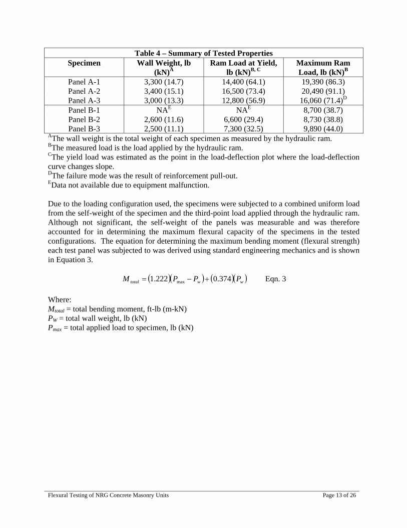
As = 0.2 in.2 (129 mm2) fy = 60,000 lb/in.2 (414 MPa) b = 40 in. (1,016 mm) f’m = 2,150 lb/in.2 (14.8 MPa) – The specified masonry compressive strength was assumed equal to the compressive strength of the solid grouted prisms containing insulation and the outside veneer face shell. Since the difference in the measured compressive strength of the prisms containing the insulation was minor, the choice of the composite masonry compressive strength (including insulation) would not affect the calculated assembly flexural strengths significantly. Then, for an effective depth to the reinforcement (d) equal to 8.625 inches (219 mm), the nominal flexural strength (Mn) is: Mn = 30,730 in-lb/ft (11,480 mm-kN/m) For an effective depth to the reinforcement (d) equal to 3.0 inches (76 mm), the nominal flexural strength (Mn) is: Mn = 10,480 in-lb/ft (3,910 mm-kN/m) To determine the design strength, the nominal strength is multiplied by a strength reduction factor (φ) equal to 0.90 per the requirements of the 2005 MSJC Building Code Requirements for Masonry Structures (Ref. 9). Hence: For an effective depth to the reinforcement (d) equal to 8.625 inches (219 mm), the design flexural strength (φMn) is: φMn = 27,660 in-lb/ft (10,330 mm-kN/m) For an effective depth to the reinforcement (d) equal to 3.0 inches (76 mm), the design flexural strength (φMn) is: φMn = 9,430 in-lb/ft (3,520 mm-kN/m) 4.2 Tested Strength of NRG Panels Each of the six NRG test panels were subjected to third-point flexural loading in accordance with ASTM E 72 as previously described. Table 4 provides a summary of the measured wall weights, yield loads, and maximum loads for each specimen. For all specimens, except Panel A-3, the failure mode was due to yielding of the reinforcement resulting in excessive deflection of the panel and loss of load-carrying capacity. For Panel A-3, failure resulted from one of the vertical reinforcing bars losing its anchorage from the end bearing course and ultimately pulling-out of the specimen. The load-deflection curves for each panel set are shown in Figures 7 and 8. Note that due to equipment failure, the deflection history and maximum displacement of Panel B-1 was not determined.
Flexural Testing of NRG Concrete Masonry Units Page 13 of 26
Table 4 – Summary of Tested Properties Specimen Wall Weight, lb
(kN)A Ram Load at Yield,
lb (kN)B, C Maximum Ram Load, lb (kN)B
Panel A-1 3,300 (14.7) 14,400 (64.1) 19,390 (86.3) Panel A-2 3,400 (15.1) 16,500 (73.4) 20,490 (91.1) Panel A-3 3,000 (13.3) 12,800 (56.9) 16,060 (71.4)D Panel B-1 NAE NAE 8,700 (38.7) Panel B-2 2,600 (11.6) 6,600 (29.4) 8,730 (38.8) Panel B-3 2,500 (11.1) 7,300 (32.5) 9,890 (44.0)
AThe wall weight is the total weight of each specimen as measured by the hydraulic ram. BThe measured load is the load applied by the hydraulic ram. CThe yield load was estimated as the point in the load-deflection plot where the load-deflection curve changes slope. DThe failure mode was the result of reinforcement pull-out. EData not available due to equipment malfunction. Due to the loading configuration used, the specimens were subjected to a combined uniform load from the self-weight of the specimen and the third-point load applied through the hydraulic ram. Although not significant, the self-weight of the panels was measurable and was therefore accounted for in determining the maximum flexural capacity of the specimens in the tested configurations. The equation for determining the maximum bending moment (flexural strength) each test panel was subjected to was derived using standard engineering mechanics and is shown in Equation 3.
( )( ) ( )( )wwtotal PPPM 374.0222.1 max +−= Eqn. 3 Where: Mtotal = total bending moment, ft-lb (m-kN) PW = total wall weight, lb (kN) Pmax = total applied load to specimen, lb (kN)

Flexural Testing of NRG Concrete Masonry Units Page 14 of 26
0
5000
10000
15000
20000
25000
0 0.5 1 1.5 2 2.5
Displacement (in.)
Load
(lb)
Panel A-1 Panel A-2 Panel A-3
Figure 7 – Load-Deflection Curves for Panel Set A
0
2000
4000
6000
8000
10000
12000
0 1 2 3 4 5 6 7 8 9
Displacement (in.)
Load
(lb)
Panel B-2 Panel B-3
Figure 8 – Load-Deflection Curves for Panel Set B

Flexural Testing of NRG Concrete Masonry Units Page 15 of 26
Using Equation 3, the total bending moment (for the entire specimen) at yield and the maximum bending moment for each test specimen are summarized in Table 5.
Table 5 – Measured Flexural Strength of NRG Panels Specimen Bending Moment at Yield,
ft-lb (mm-kN) Maximum Bending
Moment, ft-lb (mm-kN) Panel A-1 14,800 (20,060) 20,900 (28,330) Panel A-2 17,280 (23,430) 22,160 (30,040) Panel A-3 13,100 (17,760) 17,080 (23,160) Panel B-1 NA 8,510 (11,540) Panel B-2 5,860 (7,940) 8,460 (11,470) Panel B-3 6,800 (9,220) 9,970 (13,510)
For comparison to the design flexural strengths determined earlier, the tested flexural strengths shown in Table 4 are converted to a per unit length value as shown in Table 6.
Table 6 – Comparison to Codified Design Flexural Strength Specimen Nominal Flexural
Strength, ft-lb/ft (mm-kN/m)A, B
Measured Bending Moment at Yield, ft-
lb/ft (mm-kN/m)B
Measured Maximum Bending Moment, ft-
lb/ft (mm-kN/m) Panel A-1 3,700 (16,460) 5,220 (23,220) Panel A-2 4,320 (19,220) 5,540 (24,640) Panel A-3 3,270 (14,550) 4,270 (18,990) Average
2,560 (11,480)
3,760 (16,730) 5,010 (22,290) Panel B-1 NA 2,130 (9,470) Panel B-2 1,470 (6,540) 2,120 (9,430) Panel B-3 1,700 (7,560) 2,490 (11,080) Average
870 (3,910)
1,590 (7,070) 2,250 (10,010) ABased upon Equation 1 for the material properties used to construct the test specimens. BFor comparison purposes, the design strength should be compared to the measured bending moment at yield as these values would be the controlling limit state for design. Using the average flexural strength at yield for the tested NRG panels, Table 7 was developed to conceptually illustrate the maximum height for an NRG wall system using a prescribed service-level load applied uniformly over the height of the wall. While this table is based solely on the measured flexural yield strength as determined in this research project and does not take into consideration all the design variables required by current building codes (including appropriate safety factors), it does illustrate the relative effectiveness of the NRG system in resisting simulated applied loads.

Flexural Testing of NRG Concrete Masonry Units Page 16 of 26
Table 7 – Maximum Wall Heights for a Given Service-Level PressureA
Uniform Pressure lb/ft2 (kN/m2)
Maximum Wall Height for Panel Set A, ft (m)
Maximum Wall Height for Panel Set B, ft (m)
5 (0.24) 77.6 (23.6) 50.4 (15.4) 10 (0.47) 54.8 (16.7) 35.7 (10.9) 15 (0.72) 44.8 (13.6) 29.1 (8.9) 20 (0.96) 38.8 (11.8) 25.2 (7.7) 25 (1.20) 34.7 (10.6) 22.6 (6.9) 30 (1.44) 31.7 (9.7) 20.6 (6.3) 35 (1.68) 29.3 (8.9) 19.1 (5.8) 40 (1.92) 27.4 (8.4) 17.8 (5.4) 45 (2.15) 25.9 (7.9) 16.8 (5.1)
AThese values are based upon the variables tested in this research project, including material strength, reinforcement spacing and location, and unit cross-sectional properties and may not take into consideration all project-specific design variables. 5.0—CONCLUSIONS Due to the measured differences in the tested masonry prism compressive strength between the full-size units (containing both the outside veneer face shell and insulation) relative to the prisms constructed and tested without the outside veneer face shell and insulation, if the full assembly cross-section were used in estimating an element strength, the assembly compressive strength should be correspondingly based on the prism compressive strength using the full units (including the outside face shell and insulation). Alternatively, if the solid masonry ‘back-up’ portion of the assembly is used for determining the structural strength (that is, neglecting the outside veneer face shell and insulation), then a more realistic estimate of the element strength would likely be determined by using prisms constructed solely of the masonry ‘back-up’ without the outside face shell and insulation. Based upon the testing of the NRG system using rigid foam-in-place insulation, the flexural strength of this system can conservatively be estimated using conventional code-prescribed design models assuming the full cross-section of the assembly was effective in structurally resisting loads if the masonry design flexural strength was based on the full unit cross-section (that is, prisms were constructed and tested with the outside face shell veneer and insulation). Alternatively, if the solid masonry ‘back-up’ portion of the assembly is used for determining the compressive strength (that is, prisms were constructed and tested without the outside veneer face shell and insulation), then an assessment of the assembly flexural strength could be determined using reduced ‘back-up’ width of the unit. Additional flexural strength in the NRG system could be realized with the inclusion of additional flexural reinforcement. The code-prescribed design models would be applicable for common masonry applications, approved material properties, and bond patterns (including both running bond and stack bond). This research project focused solely on the performance of the NRG system in simple flexure only. The compressive strength and shear strength of the NRG assembly was not directly assessed in this research project and as such, and conclusions on these properties would be

Flexural Testing of NRG Concrete Masonry Units Page 17 of 26
speculative. It would reason, however, that the solid masonry ‘back-up’ portion of the NRG unit could reasonably be assumed to resist such applied compressive and shear loads. Further research and testing would be needed to more accurately quantify the shear and compressive strength properties of assemblies constructed with NRG units.
References
1. ASTM E 72-05, Standard Test Methods of Conducting Strength Tests of Panels for Building Construction, ASTM International, West Conshohocken, PA, 2005.
2. ASTM C 140-05a, Standard Test Methods for Sampling and Testing Concrete Masonry Units and Related Units, ASTM International, West Conshohocken, PA, 2005.
3. ASTM C 90-05a, Standard Specification for Loadbearing Concrete Masonry Units, ASTM International, West Conshohocken, PA, 2005.
4. ASTM C 270-05a, Standard Specification for Mortar for Unit Masonry, ASTM International, West Conshohocken, PA, 2005.
5. ASTM C 780-05, Standard Test Method for Preconstruction and Construction Evaluation of Mortars for Plain and Reinforced Unit Masonry, ASTM International, West Conshohocken, PA, 2005.
6. ASTM C 476-02, Standard Specification for Grout for Masonry, ASTM International, West Conshohocken, PA, 2002.
7. ASTM C 1019-05, Standard Test Method for Sampling and Testing Grout, ASTM International, West Conshohocken, PA, 2005.
8. ACI 530.1-05/ASCE 6-05/TMS 602-05 Specification for Masonry Structures, Reported by the Masonry Standards Joint Committee, The Masonry Society, Boulder, CO, 2005.
9. ACI 530-05/ASCE 5-05/TMS 402-05 Building Code Requirements for Masonry Structures, Reported by the Masonry Standards Joint Committee, The Masonry Society, Boulder, CO, 2005.

Flexural Testing of NRG Concrete Masonry Units Page 18 of 26
Appendix A – Concrete Masonry Unit Test Report ASTM C 140 Test Report Job No.: 05-520From Saw-Cut Specimens Report Date: 2/14/2006
Client: Oldcastle Architectural/Northfield Block Testing Agency: National Concrete Masonry AssociationAddress: One Hunt Court Research and Development Laboratory
Mundelein, IL 60060 Address: 13750 Sunrise Valley DriveHerndon, Virginia 20171-4662
Unit Specification: ASTM C90-05 Sampling Party: Oldcastle Architectural/Northfield Block
Unit Designation/Description:NRG Insulated BlockCompression Coupon from Face Shell
Summary of Test ResultsRequired Tested Required Tested
Physical Property Values Values1 Physical Property Values ValuesNet Compressive Strength 1900 min 4220 psi Net Cross-Sectional Area **** 9.3 in2
Gross Compressive Strength **** 4220 psiDensity **** 79.7 pcfAbsorption 18 max 11.8 pcf
Individual Unit Test Results
Properties of Saw-Cut CompressiveCompression Received Avg Avg Avg Max. StrengthSpecimens Wt, WR Width Height Length Gross Net Load Gross Net
lb in. in. in. in2 in2 lb psi psiUnit #1 1.30 1.53 3.02 6.10 9.30 9.30 36210 3890 3890Unit #2 1.29 1.53 3.02 6.09 9.31 9.31 39540 4250 4250Unit #3 1.32 1.53 3.01 6.08 9.30 9.30 42050 4520 4520Average 1.30 1.53 3.01 6.09 9.30 9.30 39270 4220 4220
Properties of Saw-CutAbsorption Received Immersed Saturated Oven-Dry NetSpecimens Wt, WR Wt, WI Wt, WS Wt, WD Absorp Density Volume
lb lb lb lb pcf pcf ft3
Unit #4 5.06 1.86 5.64 4.78 14.2 78.9 0.0606Unit #5 5.04 1.73 5.51 4.84 11.2 79.9 0.0605Unit #6 5.02 1.68 5.47 4.87 10.0 80.2 0.0607Average 5.04 1.76 5.54 4.83 11.8 79.7 0.0606
Comments: These tested properties meet or exceed the applicable requirements Robert Thomas of ASTM C 90-05. Vice President ofEngineering
Cross-Sectional Area
Note: Due to the unique configuration of the units, coupon specimens were saw-cut from full-size units in accordance with the requirements of ASTM C 140 to determine unit compressive strength, absorption, and density characteristics.
1 Reported values are based on the properties of saw cut absorption and compression specimens.

Flexural Testing of NRG Concrete Masonry Units Page 19 of 26
Appendix B – Mortar Test Results NCMA Research and Development LaboratoryASTM C 780Preconstruction and Construction Evaluation of Mortars for Plain and Reinforced Unit Masonry
Job No.: 05-520Client: Oldcastle Architectural/Northfield Block Corresponding Wall/Specimen: NRG PanelsAddress: One Hunt Court Mortar Type: S MC
Mundelein, IL 60060
NCMA Lab Aggregate Unit Weight = 80 pcfWeight of Cement Bag = 75 lb.
Batch Information (C270)
Batch Factor = Agg Wt /(Agg Unit Wt x Agg. Vol. Proportion) = 100 / ( 80 x 3 ) = 0.416Cement Weight = Cmt Prop x Bag Weight x Batch Factor = 1 x 75 x 0.416 = 31.2 lb.
Volume WeightProportions (lb.)
31.2 Mixed By: DL100 Date: 2/6/06
Varies
Total Wt. = 131.2
2-inch Cube Compressive Strength (C 780 / C 109)Cube Age: 28 days Cube
Cube Wt Load StrengthCube # (g) (lbs) (psi)
1 263.5 10380 25952 261.1 10140 25353 261.5 10530 2633
Average 262.0 10350.0 2590
Testing by: DL Date: 2/6/06
Cone Penetration (C 780)Initial Penetration = 62.0 mm Tested By: DL
Date: 12/6/05
Robert ThomasVice President of Engineering
Tap WaterLab C 144LAFARGE
NoneNone
None
Type/Brand/SourceMaterial
Masonry Cement
Admixture
LimePortland Cement
Masonry SandWater Added to Mix

Flexural Testing of NRG Concrete Masonry Units Page 20 of 26
Appendix C – Grout Test Report NCMA Research and Development LaboratoryASTM C 1019-05: Sampling and Testing Grout
Project No.: 05-520Report Date: 2/14/2006
Client: Oldcastle Architectural/Northfield Block Testing Agency: National Concrete Masonry AssociationAddress: One Hunt Court Research and Development Laboratory
Mundelein, IL 60060 Address: 13750 Sunrise Valley DriveHerndon VA, 20171-4662
Project /Description: NRG Flexural Testing Sampling Party: NCMA
Mix Design: Bulk Sack Mix - Set 1 Date Made: 1/27/2006Date Rec'd: NADate Tested: 2/6/2006Tested By: DL
Specimen 1 Specimen 2 Specimen 3 AverageHeight (in.) 1 7.50 7.40 7.50(H = 2W) 2 7.50 7.50 7.50
3 7.50 7.40 7.504 7.60 7.50 7.50
Average 7.53 7.45 7.50 7.492
Width (in.) 1 3.60 3.80 4.00(> 3 inches) 2 3.70 3.80 4.00
3 3.60 3.90 3.904 3.70 4.00 3.80
Average 3.65 3.88 3.93 3.817Weight (lb.) 7.87 8.11 8.70 8.227Plumb (in.) 0.125 0.125 0.125 0.125Plumb (%) 2 2 2 2Compressive Load (lb.) 32450 32700 38700 34617Compressive Strength (psi) 2436 2178 2512 2380
Curing Conditions: 2 days in mold7 days in curing cabinet
Robert ThomasVice President of Engineering

Flexural Testing of NRG Concrete Masonry Units Page 21 of 26
NCMA Research and Development LaboratoryASTM C 1019-05: Sampling and Testing Grout
Project No.: 05-520Report Date: 2/14/2006
Client: Oldcastle Architectural/Northfield Block Testing Agency: National Concrete Masonry AssociationAddress: One Hunt Court Research and Development Laboratory
Mundelein, IL 60060 Address: 13750 Sunrise Valley DriveHerndon VA, 20171-4662
Project /Description: NRG Flexural Testing Sampling Party: NCMA
Mix Design: Laboratory Mix - Set 2 Date Made: 1/31/2006Date Rec'd: NADate Tested: 2/6/2006Tested By: DL
Specimen 1 Specimen 2 Specimen 3 AverageHeight (in.) 1 7.80 7.60 7.70(H = 2W) 2 7.80 7.60 7.70
3 7.80 7.60 7.704 7.80 7.60 7.70
Average 7.80 7.60 7.70 7.70
Width (in.) 1 3.50 3.60 4.00(> 3 inches) 2 3.50 3.50 4.00
3 3.50 3.50 3.604 3.50 3.50 3.60
Average 3.50 3.53 3.80 3.61Weight (lb.) 7.52 7.61 8.59 7.91Plumb (in.) 0.125 0.125 0.125 0.125Plumb (%) 2 2 2 2Compressive Load (lb.) 37990 35910 41110 38337Compressive Strength (psi) 3101 2890 2847 2950
Curing Conditions: 2 days in mold5 days in curing cabinet
Robert ThomasVice President of Engineering

Flexural Testing of NRG Concrete Masonry Units Page 22 of 26
Appendix D – Prism Test Reports ASTM C 1314-03b Test Report: Project No.: 05-520-01 Constructing and Testing Masonry Prisms Used to Determine Report Date: 02/17/06 Compliance with Specified Compressive Strength of Masonry
Client: Oldcastle Architectural/Northfield Block Testing Lab: National Concrete Masonry AssociationAddress: One Hunt Court Research and Development Laboratory
Mundelein, IL 60060 13750 Sunrise Valley DriveHerdon VA, 20171-4662
Project Identification: 05-520-01Prism Identification: 12 x 16 x 16, Hollow, Stack Bond, Concrete Masonry Prism
Face shell mortar bedding onlySpecified Compressive Strength of Masonry NA
Prism Details: Masonry Unit Information:Number of Mortar Bed Joints: 1 Unit Supplier: Oldcastle ArchNumber of Masonry Units Used: 2 Unit Dimensions: 12 x 8 x 16Date Retrieved from Site: NA Unit Net Area (hollow units): 95.71Date Delivered to Lab: NADate Tested: 2/6/2006
Mortar Information Grout InformationMortar Supplier / Preparer: NCMA Grout Supplier / Preparer: NAMortar Type / Description: S Grout Type / Description NA
Grout Slump (ASTM C 143): NACompression Test Machine Information Method of Consolidation: NADiameter of Spherical Seat: 10 in.Required Upper Bearing Plate Thickness: 4.8 in.Required Lower Bearing Plate Thickness: 1.0 in.
in. Provided Upper Bearing Plate Thickness: 5.1 in.Tested Prism Properties: in. Provided Lower Bearing Plate Thickness: 2.5 in.
Gross CorrectedAge Avg. Avg. Avg. Gross Max Compr. Gross
Prism at Test Width Height Length Area Load Strength h/t h/t StrengthNo. (days) (in.) (in.) (in.) (in2) (lb.) (psi) Ratio CF* (psi)
1 62 11.65 15.78 15.68 182.61 116000 635 1.35 0.78 5002 62 11.60 15.65 15.65 181.54 114540 631 1.35 0.78 4903 62 11.60 15.65 15.60 180.96 125460 693 1.35 0.78 540
Average 510
Net CorrectedNet Max Compr. Net
Prism Area Load Strength h/t h/t StrengthNo. (in2) (lb.) (psi) Ratio CF* (psi)
1 44.9 116000 2582 1.35 0.78 20102 44.9 114540 2550 1.35 0.78 19803 44.9 125460 2793 1.35 0.78 2170
Average 2050* Height to thickness correction factor from Table 1 of ASTM C 1314-03b. Values have been linearly interpolated as necessary.
Robert ThomasVice President of Engineering
Net cross-section area of units based upon the minimum net face shell bedded surface of the prisms using

Flexural Testing of NRG Concrete Masonry Units Page 23 of 26
ASTM C 1314-03b Test Report: Project No.: 05-520-02 Constructing and Testing Masonry Prisms Used to Determine Report Date: 02/17/06 Compliance with Specified Compressive Strength of Masonry
Client: Oldcastle Architectural/Northfield Block Testing Lab: National Concrete Masonry AssociationAddress: One Hunt Court Research and Development Laboratory
Mundelein, IL 60060 13750 Sunrise Valley DriveHerdon VA, 20171-4662
Project Identification: 05-520-02Prism Identification: 12 x 16 x 16, Hollow, Stack Bond, Concrete Masonry Prism
Full mortar bedding onlySpecified Compressive Strength of Masonry NA
Prism Details: Masonry Unit Information:Number of Mortar Bed Joints: 1 Unit Supplier: Oldcastle ArchNumber of Masonry Units Used: 2 Unit Dimensions: 12 x 8 x 16Date Retrieved from Site: NA Unit Net Area (hollow units): 95.71Date Delivered to Lab: NADate Tested: 2/6/2006
Mortar Information Grout InformationMortar Supplier / Preparer: NCMA Grout Supplier / Preparer: NAMortar Type / Description: S Grout Type / Description NA
Grout Slump (ASTM C 143): NACompression Test Machine Information Method of Consolidation: NADiameter of Spherical Seat: 10 in.Required Upper Bearing Plate Thickness: 4.8 in.Required Lower Bearing Plate Thickness: 1.0 in.
in. Provided Upper Bearing Plate Thickness: 5.1 in.Tested Prism Properties: in. Provided Lower Bearing Plate Thickness: 2.5 in.
Gross CorrectedAge Avg. Avg. Avg. Gross Max Compr. Gross
Prism at Test Width Height Length Area Load Strength h/t h/t StrengthNo. (days) (in.) (in.) (in.) (in2) (lb.) (psi) Ratio CF* (psi)
1 62 11.60 15.70 15.70 182.12 216490 1189 1.35 0.78 9302 62 11.60 15.70 15.70 182.12 228780 1256 1.35 0.78 9803 62 11.60 15.65 15.60 180.96 284970 1575 1.35 0.78 1220
Average 1040
Net CorrectedNet Max Compr. Net
Prism Area Load Strength h/t h/t StrengthNo. (in2) (lb.) (psi) Ratio CF* (psi)
1 95.7 216490 2262 1.35 0.78 17602 95.7 228780 2390 1.35 0.78 18603 95.7 284970 2977 1.35 0.78 2310
Average 1980* Height to thickness correction factor from Table 1 of ASTM C 1314-03b. Values have been linearly interpolated as necessary.
Robert ThomasVice President of Engineering
Net cross-section area of units based upon the mortared surface area using minimum specified dimensions.

Flexural Testing of NRG Concrete Masonry Units Page 24 of 26
ASTM C 1314-03b Test Report: Project No.: 05-520-03 Constructing and Testing Masonry Prisms Used to Determine Report Date: 02/17/06 Compliance with Specified Compressive Strength of Masonry
Client: Oldcastle Architectural/Northfield Block Testing Lab: National Concrete Masonry AssociationAddress: One Hunt Court Research and Development Laboratory
Mundelein, IL 60060 13750 Sunrise Valley DriveHerdon VA, 20171-4662
Project Identification: 05-520-03Prism Identification: 12 x 16 x 16, Grouted, Stack Bond, Concrete Masonry Prism
Solid Grouted PrismSpecified Compressive Strength of Masonry NA
Prism Details: Masonry Unit Information:Number of Mortar Bed Joints: 1 Unit Supplier: Oldcastle ArchNumber of Masonry Units Used: 2 Unit Dimensions: 12 x 8 x 16Date Retrieved from Site: NA Unit Net Area (hollow units): 95.71Date Delivered to Lab: NADate Tested: 2/6/2006
Mortar Information Grout InformationMortar Supplier / Preparer: NCMA Grout Supplier / Preparer: NCMAMortar Type / Description: S Grout Type / Description Course
Grout Slump (ASTM C 143): 8 in. +Compression Test Machine Information Method of Consolidation: MechanicalDiameter of Spherical Seat: 10 in.Required Upper Bearing Plate Thickness: 4.7 in.Required Lower Bearing Plate Thickness: 1.0 in.
in. Provided Upper Bearing Plate Thickness: 5.1 in.Tested Prism Properties: in. Provided Lower Bearing Plate Thickness: 2.5 in.
Gross CorrectedAge Avg. Avg. Avg. Gross Max Compr. Gross
Prism at Test Width Height Length Area Load Strength h/t h/t StrengthNo. (days) (in.) (in.) (in.) (in2) (lb.) (psi) Ratio CF* (psi)
1 7 11.60 16.00 15.60 180.96 365710 2021 1.38 0.79 16002 7 11.58 16.08 15.65 181.15 378670 2090 1.39 0.80 16703 7 11.55 16.05 15.65 180.76 371300 2054 1.39 0.80 1640
Average 1640
Net CorrectedNet Max Compr. Net
Prism Area Load Strength h/t h/t StrengthNo. (in2) (lb.) (psi) Ratio CF* (psi)
1 138.0 365710 2650 1.38 0.79 21002 138.0 378670 2744 1.39 0.80 21903 138.0 371300 2691 1.39 0.80 2150
Average 2150* Height to thickness correction factor from Table 1 of ASTM C 1314-03b. Values have been linearly interpolated as necessary.
Robert ThomasVice President of Engineering
Net cross-section area of units based upon the mortared surface area using minimum specified dimensions.

Flexural Testing of NRG Concrete Masonry Units Page 25 of 26
ASTM C 1314-03b Test Report: Project No.: 05-520-04 Constructing and Testing Masonry Prisms Used to Determine Report Date: 02/17/06 Compliance with Specified Compressive Strength of Masonry
Client: Oldcastle Architectural/Northfield Block Testing Lab: National Concrete Masonry AssociationAddress: One Hunt Court Research and Development Laboratory
Mundelein, IL 60060 13750 Sunrise Valley DriveHerdon VA, 20171-4662
Project Identification: 05-520-04Prism Identification: 6 x 16 x 8, Grouted, Stack Bond, Concrete Masonry Prism
Half-Length, Solid Grouted Prism with Insulation and Veneer RemovedSpecified Compressive Strength of Masonry NA
Prism Details: Masonry Unit Information:Number of Mortar Bed Joints: 1 Unit Supplier: Oldcastle ArchNumber of Masonry Units Used: 2 Unit Dimensions: 12 x 8 x 16Date Retrieved from Site: NA Unit Net Area (hollow units): 95.71Date Delivered to Lab: NADate Tested: 4/7/2006
Mortar Information Grout InformationMortar Supplier / Preparer: NCMA Grout Supplier / Preparer: NCMAMortar Type / Description: S Grout Type / Description Course
Grout Slump (ASTM C 143): 8 in. +Compression Test Machine Information Method of Consolidation: MechanicalDiameter of Spherical Seat: 10 in.Required Upper Bearing Plate Thickness: 0.5 in.Required Lower Bearing Plate Thickness: 1.0 in.
in. Provided Upper Bearing Plate Thickness: 5.1 in.Tested Prism Properties: in. Provided Lower Bearing Plate Thickness: 2.5 in.
Gross CorrectedAge Avg. Avg. Avg. Gross Max Compr. Gross
Prism at Test Width Height Length Area Load Strength h/t h/t StrengthNo. (days) (in.) (in.) (in.) (in2) (lb.) (psi) Ratio CF* (psi)
1 9 6.20 15.80 9.20 56.8 161900 2851 2.55 1.04 29702 9 6.25 15.80 9.20 56.8 161460 2843 2.53 1.04 29603 9 6.25 15.80 9.20 56.8 163210 2874 2.53 1.04 2990
Average 2970
Net CorrectedNet Max Compr. Net
Prism Area Load Strength h/t h/t StrengthNo. (in2) (lb.) (psi) Ratio CF* (psi)
1 56.8 161900 2851 2.55 1.04 29702 56.8 161460 2843 2.53 1.04 29603 56.8 163210 2874 2.53 1.04 2990
Average 2970* Height to thickness correction factor from Table 1 of ASTM C 1314-03b. Values have been linearly interpolated as necessary.
Robert ThomasVice President of Engineering
Net cross-section area of units based upon the total cross-sectional area using minimum specified dimensions.

Flexural Testing of NRG Concrete Masonry Units Page 26 of 26
ASTM C 1314-03b Test Report: Project No.: 05-520-05 Constructing and Testing Masonry Prisms Used to Determine Report Date: 02/17/06 Compliance with Specified Compressive Strength of Masonry
Client: Oldcastle Architectural/Northfield Block Testing Lab: National Concrete Masonry AssociationAddress: One Hunt Court Research and Development Laboratory
Mundelein, IL 60060 13750 Sunrise Valley DriveHerdon VA, 20171-4662
Project Identification: 05-520-05Prism Identification: 6 x 16 x 8, Hollow, Stack Bond, Concrete Masonry Prism
Half-Length, Hollow Prism with Insulation and Veneer RemovedSpecified Compressive Strength of Masonry NA
Prism Details: Masonry Unit Information:Number of Mortar Bed Joints: 1 Unit Supplier: Oldcastle ArchNumber of Masonry Units Used: 2 Unit Dimensions: 12 x 8 x 16Date Retrieved from Site: NA Unit Net Area (hollow units): 95.71Date Delivered to Lab: NADate Tested: 4/7/2006
Mortar Information Grout InformationMortar Supplier / Preparer: NCMA Grout Supplier / Preparer: NCMAMortar Type / Description: S Grout Type / Description Course
Grout Slump (ASTM C 143): 8 in. +Compression Test Machine Information Method of Consolidation: MechanicalDiameter of Spherical Seat: 10 in.Required Upper Bearing Plate Thickness: 0.6 in.Required Lower Bearing Plate Thickness: 1.0 in.
in. Provided Upper Bearing Plate Thickness: 5.1 in.Tested Prism Properties: in. Provided Lower Bearing Plate Thickness: 2.5 in.
Gross CorrectedAge Avg. Avg. Avg. Gross Max Compr. Gross
Prism at Test Width Height Length Area Load Strength h/t h/t StrengthNo. (days) (in.) (in.) (in.) (in2) (lb.) (psi) Ratio CF* (psi)
1 24 6.30 15.80 9.20 56.8 107920 1900 2.51 1.04 19802 24 6.30 15.85 9.20 56.8 120090 2115 2.52 1.04 22003 24 6.28 15.85 9.20 56.8 94680 1667 2.53 1.04 1740
Average 1970
Net CorrectedNet Max Compr. Net
Prism Area Load Strength h/t h/t StrengthNo. (in2) (lb.) (psi) Ratio CF* (psi)
1 35.6 107920 3028 2.51 1.04 31502 35.6 120090 3370 2.52 1.04 35103 35.6 94680 2657 2.53 1.04 2770
Average 3140* Height to thickness correction factor from Table 1 of ASTM C 1314-03b. Values have been linearly interpolated as necessary.
Robert ThomasVice President of Engineering
Net cross-section area of units based upon the mortared surface area using minimum specified dimensions.


