16
For internal use only 1 © Nokia Siemens Networks Presentation / Author / Date Radio Bearer Control & DRX/DTX Management LTEPAR Pilot Düsseldorf CW 22 2010 LTE Radio Parameters RL10

For internal use only1 © Nokia Siemens Networks Presentation / Author / Date
Radio Bearer Control & DRX/DTX Management
LTEPAR Pilot Düsseldorf CW 22 2010
LTE Radio Parameters RL10

For internal use only2 © Nokia Siemens Networks
Nokia Siemens Networks Academy
Legal notice
Intellectual Property RightsAll copyrights and intellectual property rights for Nokia Siemens Networks training
documentation, product documentation and slide presentation material, all of which are forthwith known as Nokia Siemens Networks training material, are the exclusive property of Nokia Siemens Networks. Nokia Siemens Networks owns the rights to copying, modification, translation, adaptation or derivatives including any improvements or developments. Nokia Siemens Networks has the sole right to copy, distribute, amend, modify, develop, license, sublicense, sell, transfer and assign the Nokia Siemens Networks training material. Individuals can use the Nokia Siemens Networks training material for their own personal self-development only, those same individuals cannot subsequently pass on that same Intellectual Property to others without the prior written agreement of Nokia Siemens Networks. The Nokia Siemens Networks training material cannot be used outside of an agreed Nokia Siemens Networks training session for development of groups without the prior written agreement of Nokia Siemens Networks.

For internal use only4 © Nokia Siemens Networks
Radio Bearer Control & DRX/DTX Management
• After completing this learning element, the participant should be able to:
• State different connection / activity states of an LTE UE in comparison to UMTS
• Identify performance related aspects of the feature
• Describe different transitions and relevant triggers as e.g. activity/inactivity detection
• State the possible configuration choices for DRX/DTX in RL09

For internal use only5 © Nokia Siemens Networks
States in UTRAN, GERAN, E-UTRA
• The 3 transitions supported by the RL 09/10 LTE Inter working features
Handover
CELL_PCH
URA_PCH
CELL_DCH
UTRA_Idle
E-UTRA RRC_CONNECTED
E-UTRA RRC_IDLE
GSM_Idle/GPRS Packet_Idle
GPRS Packet transfer mode
GSM_Connected
Handover
Reselection Reselection
Reselection
Connection establishment/release
Connection establishment/release
Connection establishment/release
CCO, Reselection
CCO with optional
NACC
CELL_FACH
CCO, Reselection
Supported by feature
RL20
3G LTE GSM
Supported RL10
Supported by feature
RL10
Supported by feature
RL10

For internal use only6 © Nokia Siemens Networks
Definition of main EPS Mobility Management states• EMM-DEREGISTERED
– The UE is not reachable by a MME.
– UE context can still be stored in the UE and MME
• EMM-REGISTERED– UE enters to EMM-Registered with Attach or Tracking Area Update procedure
– The UE location is known with accuracy of the tracking area list
– UE has at least one active PDN connection
– After Detach procedure the state is changed to EMM-DEREGISTERED
UE state handling :Mobility Management States
Attach accept
DetachAttach rejectTAU Reject
All Bearer Deactivated
EMM-DEREGISTERED EMM-REGISTERED
EMM states in UE
Attach acceptTAU Accept
DetachAttach rejectTAU Reject
All Bearer Deactivated
EMM-DEREGISTERED EMM-REGISTERED
EMM states in MME

For internal use only7 © Nokia Siemens Networks
Definition of EPS Connection Management states• ECM-IDLE
– UE is in ECM-IDLE state when no NAS signalling connection between UE and network exists.
– In the EMM-REGISTERED and ECM-IDLE state, the UE shall perform: Tracking Area Update Periodic Tracking Area Update Service Request Answer to paging from MME with Service Request
– UE and MME enter the ECM-CONNECTED state when signaling connection is established.
• ECM-CONNECTED– UE location is known in the MME with an accuracy of a serving eNodeB.
– For a UE in the ECM-CONNECTED state, there exists a signalling connection between the UE and the MME.
– The S1 release procedure changes the state at both UE and MME from ECM-CONNECTED to ECM-IDLE.
UE state handling :Mobility Management States
RRC Established
RRC Released
EMM-IDLE EMM-CONNECTED
EMC states in UE
S1 Established
S1 Released
EMM-IDLE EMM-CONNECTED
EMM states in MME

For internal use only8 © Nokia Siemens Networks
DRX/DTX – General Motivation is the Challenge –> Battery Capacity Increases only Slowly Compared to Moore’s Law
Joseph A. Paradiso Massachusetts Institute of Technology Media Laboratory, Thad Starner Georgia Institute of Technology, GVU Center “Energy Scavenging for Mobile and Wireless Electronics”, Pervasive Computing, IEEE Volume 4, Issue 1, Jan.-March 2005 Page(s):18 - 27 Digital Object Identifier 10.1109/MPRV.2005.9
CPU by Moore’s law = double
every 18 months
Battery capacity double every 12
years
Battery savings
are a must and
are proportional to
active/inactive ratio
For internal use only9 © Nokia Siemens Networks
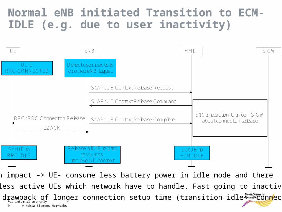
Normal eNB initiated Transition to ECM-IDLE (e.g. due to user inactivity)
eNBUE MME S-GW
S1AP: UE Context Release Command
S1AP: UE Context Release CompleteRRC: RRC Connection Release
Release all UE related resources,
remove UE context
Set UE to RRC-IDLE
Set UE to ECM-IDLE
Detect user inactivityor other eNB trigger
S1AP: UE Context Release Request
S11 interaction to inform S-GWabout connection release
UE inRRC-CONNECTED
L2 ACK
Main impact –> UE- consume less battery power in idle mode and there
Is less active UEs which network have to handle. Fast going to inactivity
Has drawback of longer connection setup time (transition idle<->connected)

For internal use only10 © Nokia Siemens Networks
UE_INACTIVITY DETECTION/MEASUREMENT
T_INACTIVE

For internal use only11 © Nokia Siemens Networks
In-Actvity Timer
Parameter, abbreviated Name
Description Access
RWR
Parameter Type
O: Operator configurableV: Vendor configurable
Range, Step size / Granularity, Units, Special Value
Default Value
Parameter Scope(PLMN, RAN, Nb, Cell, Chl),Proposed MOC
Reference e.g. 3GPP name or other
Multiplicity
(mand) (mand) (mand) (mand) (mand) (opt) (mand) (opt) (mand)
T_INACTIVE Time period for UE inactivity detection; the same value is used for UL and DL direction.
RW O 10..65535step size: 1unit: seconds0: disabled
300 Cell NA 1
INPUT

For internal use only13 © Nokia Siemens Networks
DTX/DRX, Discontinuous Reception
• Discontinuous reception/transmission means UE transceiver is switched off for some predefined time periods. This save power consumption on one side but might consequences in longer call setup time and/or lower user throughput achievable.
• What are DRX/DTX options?
• In Idle mode for Paging – this option means UE is listening paging messages in predefined time opportunities only and sleeping all other time. Supported in RL10.
• DRX/DTX in connected mode – UE is switched off for predefined time interval. Not supported for RL10.

For internal use only14 © Nokia Siemens Networks
Discontinuous Reception for paging (TS 36.304)
The UE may use Discontinuous Reception (DRX) in idle mode in order to reduce power consumption. One Paging Occasion (PO) is a subframe where there may be P-RNTI transmitted on PDCCH addressing the paging message. One Paging Frame (PF) is one Radio Frame, which may contain one or multiple Paging Occasion(s). When DRX is used the UE needs only to monitor one PO per DRX cycle.

For internal use only15 © Nokia Siemens Networks
Paging Related DRX/DTX Parameters in RL09
• defaultPagingCycle– The Default Paging Cycle defines the cell specific paging DRX cycle duration. It
also determines the maximum paging DRX duration applicable in the cell. Referred to as ' T ' in TS 36.304. Value 32rf corresponds to 32 radio frames, 64rf corresponds to 64 radio frames and so on (possible vales to set are 32rf (0), 64rf (1), 128rf (2), 256rf (3), default 128rf).
– One rf means radio frame = 10ms in time– Increasing parameter value save battery capacity in idle mode as listening to
paging is less frequent, but mean call setup time is getting longer due to longer average paging time.
• pagingNb– Paging nB defines the number of possible paging occasions per radio frame,
i.e. the density of paging occasions. This parameter is used to calculate the number of paging occasions within one paging DRX duration, which in turn is used to calculate the paging occasion. (possible values to set are RL09 are oneT (2), halfT (3), quarterT (4), oneEighthT (5), oneSixteenthT (6), oneThirtySecondT (means 1/32 as per TR36.304) (7), default is quarterT).
– Side values existing in RL10 3GPP defines also possible values fourT and twoT which are not implemented in RL10. Reason – more than 1 paging occasion per radio frame seems unrealistic.

For internal use only16 © Nokia Siemens Networks
Occasion of Paging Messages
• The cell specific DRX cycle length Tsib is broadcasted by System Information (PCCH-Config parameter defaultPagingCycle (in number of radio frames) - defined by O&M).
• The UE specific DRX cycle length Tue might be received from core network from S1AP Paging Message as Optional IE.
• The used paging DRX Cycle T (in number of radio frames) is set to:T=MIN(Tue,Tsib). (Referred to as ' T ' in 3GPP TS 36.304)
• The relationship “paging occasions - radio frame” is given by the parameter pagingNb provided in System Information (PCCH-Config parameter pagingNb). nB shall be interpreted as a calculation formula (how to derive paging occasions from T). For better understanding, the result of the calculation formula nB will be written as nB(T) in this section.Example: quarterT denotes nB(T)= 1/4*T (there is one paging occasion in every 4th radio frame).

For internal use only17 © Nokia Siemens Networks
Occasion of Paging Messages – Explain of Variables as per SFS (UE Behavior)
• Paging capacity is not a limiting factor as the Paging Channel (PCH) is mapped dynamically on the PDSCH.
• The factor (T div N) gives the distance of radio frames with paging occasions. The calculation of the factor (T div N) is 2(i-k).
• The factor (UE_ID mod N) gives a relative index of a radio frame with paging occasions inside a Paging DRX cycle. The calculation of factor (UE_ID mod N) is a simple mask operation for the last k bits.
• The product (T div N)*(UE_ID mod N) gives the relative position of a radio frame with paging occasions relative to the start of a Paging_DRX cycle.
• (SFN mod T) provides a SFN numbering relative to the start of a Paging-DRX cycle. The calculation of factor (SFN mod T) is a simple mask operation for the last i bits.
• Example of paging with impact of mean paging time: Microsoft Excel Worksheet

For internal use only18 © Nokia Siemens Networks
Example (as per UE Behaviour SFS, simplified, note the Tue is smaller than allowed by 3GPP):
Cell paging DRX Tsib = 32,nB(T)=halfT,UE paging DRX Tue = 8*,T = MIN(Tue,Tsib) = MIN(8,32) = 8,nB(T) = half(8) = 4,N = MIN(T,nB(T)) = MIN(8,4) = 4,Ns = MAX(1, nB(T)/T) = MAX(1, 4 / 8) = MAX(1,0)=1,UE_ID = 3, assumption for this example (it could be any number)T div N = 8 div 4 = 2,UE_ID mod 4 = 3 (assumption for this example),(T div N)*(UE_ID mod 4) = 2*3 = 6,Let next reachable SFN = 501; therefore (SFN mod T) = 5; therefore SFN for paging
is 501+(6-5)=502.
Simplified case as the Tue is smaller than allowed by 3GPP.
SFN
T div N
T (Paging DRX)Paging OccasionPO
[SFN=x*T] [SFN=(x+1)*T]
(T div N)*(UE_ID mod N)


![TEMPERATURE LIMITER RL10 do pobrania/RL10/RL10_servic… · RL10-09 User's manual [Wpisz tekst] [Wpisz tekst]9 10 Some parameters may not be visible - this depends on the current](https://static.documents.pub/doc/80x56/606b09270b0c697eec2e56d4/temperature-limiter-rl10-do-pobraniarl10rl10servic-rl10-09-users-manual-wpisz.jpg)


