+ All Categories
Home > Documents > 06 TM51176EN01GLA2 Procedures

06 TM51176EN01GLA2 Procedures

Date post: 09-Jul-2016
Category:
Upload: -
View: 212 times
Download: 0 times
Share this document with a friend
Description:
06 TM51176EN01GLA2 Procedures
64
Procedures TM51176EN01GLA2 © 2009 Nokia Siemens Networks 1 Contents 1 Physical Layer Measurements 3 1.1 Introduction 4 1.2 Examples of measurement items 4 2 Synchronization 9 3 Idle Mode Procedures 13 3.1 Overall process 14 3.2 PLMN selection 14 3.3 Service types 16 3.4 Cell selection and reselection 18 3.5 Selection procedure and criteria 20 3.6 Cell selection: evaluation process 22 4 Timing Advance 29 5 Power Control 33 5.1 Generic 34 5.2 Downlink 36 5.3 Uplink 38 6 Random Access 39 6.1 Generic 40 6.2 Contention resolution 42 6.3 Power ramping 44 6.4 RACH performance 46 7 Physical DL-SCH related Procedures 49 7.1 Resource allocation 50 7.2 Modulation and TB size 52 7.3 CQI, PMI and RI reporting 56 8 HARQ 59 Procedures
Transcript

Procedures

TM51176EN01GLA2

© 2009 Nokia Siemens Networks 1

Contents 1 Physical Layer Measurements 3 1.1 Introduction 4 1.2 Examples of measurement items 4 2 Synchronization 9 3 Idle Mode Procedures 13 3.1 Overall process 14 3.2 PLMN selection 14 3.3 Service types 16 3.4 Cell selection and reselection 18 3.5 Selection procedure and criteria 20 3.6 Cell selection: evaluation process 22 4 Timing Advance 29 5 Power Control 33 5.1 Generic 34 5.2 Downlink 36 5.3 Uplink 38 6 Random Access 39 6.1 Generic 40 6.2 Contention resolution 42 6.3 Power ramping 44 6.4 RACH performance 46 7 Physical DL-SCH related Procedures 49 7.1 Resource allocation 50 7.2 Modulation and TB size 52 7.3 CQI, PMI and RI reporting 56 8 HARQ 59

Procedures

Procedures

TM51176EN01GLA2© 2009 Nokia Siemens Networks

2

Procedures

TM51176EN01GLA2

© 2009 Nokia Siemens Networks 3

1 Physical Layer Measurements

Procedures

TM51176EN01GLA2© 2009 Nokia Siemens Networks

4

1.1 Introduction One of the key services provided by the physical layer is the measurement of various quantities, which are used to trigger or perform a multitude of functions. Both the UE and EUTRAN are required to perform a variety of measurements. To initiate a specific measurement the UTRAN transmit a “measurement control message” to the UE. Included is a measurement identifier and type, the measurement objects and quantity, the reporting quantities, criteria (periodical or event) and mode (acknowledged or unacknowledged). Reporting events are defined which trigger the UE to send a report to the UTRAN. When the reporting criterion is fulfilled the UE answers with a “measurement report message” to the UTRAN including the measurement identifier and the results.

1.2 Examples of measurement items REFERENCE SIGNAL RECEIVED POWER (RSRP) The received power on the resource elements that carry cell-specific reference signals define the RSRP. The number of resource elements is depending on the UE implementation. All shall be averaged. The RSRP represents the received level. Hence it is given by transmitted power and pathless. PL = referenceSignalPower – higher layer filtered RSRP.

Procedures

TM51176EN01GLA2

© 2009 Nokia Siemens Networks 5

. . . . . . . . . . . . . . . . . . . . . . . . . . . . . . . . . . . . . . . . . . . . . . . . . . . . . . . . . . . . . . . . . . . . . . . . . . . . . . . . . . . . . . . . . . . . . . . . . . . . . . . . . . . . . . . . . . . . . . . . . . . . . . . . . . . . . . . . . . . . . . . . . . . . . . . . . . . . . . . . . . . . . . . . . . . . . . . . . . . . . . . . . . . . . . . . . . . . . . . . . . . . . . . . . . . . . . . . . . . . . . . . . . . . . . . . . . . . . . . . . . . . . . . . . . . . . . . . . . . . . . . . . . . . . . . . . . . . . . . . . . . . . . . . . . . . . . . . . . . . . . . . . . . . . . . . . . . . . . . . . . . . . . . . . . . . . . . . . . . . . . . . . . . . . . . . . . . . . . . . . . . . . . . . . . . . . . . . . . . . . . . . . . . . . . . . . . . . . . . . . . . . . . . . . . . . . . . . . . . . . . . . . . . . . . . . . . . . . . . . . . . . . . . . . . . . . . . . . . . . . . . . . . . . . . . . . . . . . . . . . . . . . . . . . . . . . . . . . . . . . . . . . . . . . . . . . . . . . . . . . . . . . . . . . . . . . . . . . . . . . . . . . . . . . . . . . . . . . . . . . . . . . . . . . . . . . . . . . . . . . . . . . . . . . . . . . . . . . . . . . . . . . . . . . . . . . . . . . . . . . . . . . . . . . . . . . . . . . . . . . . . . . . . . . . . . . . . . . . . . . . . . . . . . . . . . . . . . . . . . . . . . . . . . . . . . . . . . . . . . . . . . . . . . . . . . . . . . . . . . . . . . . . . . . . . . . . . . . . . . . . . . . . . . . . . . . . . . . . . . . . . . . . . . . .

Definition Is the power received power on the resource elements that carry cell-specific reference signals.

Applicable Idle mode, connected mode (intra and inter frequency)

Range [dBm]

Reference Signals

Averaged Power of Reference Signals

RSRP

Fig. 1 Reference signal received power (RSRP).

Procedures

TM51176EN01GLA2© 2009 Nokia Siemens Networks

6

1.2.1 Reference Signal Received Quality (RSRQ) Is the relation of N times the Reference Signal Received Power divided by the total received power in the channel bandwidth, i.e. RSRQ is identical to N*RSRQ/RSSI. Within the RSRQ also the noise and interference contributions are considered. Note, RSRQ/RSSI shall be taken from the same resource blocks

Procedures

TM51176EN01GLA2

© 2009 Nokia Siemens Networks 7

. . . . . . . . . . . . . . . . . . . . . . . . . . . . . . . . . . . . . . . . . . . . . . . . . . . . . . . . . . . . . . . . . . . . . . . . . . . . . . . . . . . . . . . . . . . . . . . . . . . . . . . . . . . . . . . . . . . . . . . . . . . . . . . . . . . . . . . . . . . . . . . . . . . . . . . . . . . . . . . . . . . . . . . . . . . . . . . . . . . . . . . . . . . . . . . . . . . . . . . . . . . . . . . . . . . . . . . . . . . . . . . . . . . . . . . . . . . . . . . . . . . . . . . . . . . . . . . . . . . . . . . . . . . . . . . . . . . . . . . . . . . . . . . . . . . . . . . . . . . . . . . . . . . . . . . . . . . . . . . . . . . . . . . . . . . . . . . . . . . . . . . . . . . . . . . . . . . . . . . . . . . . . . . . . . . . . . . . . . . . . . . . . . . . . . . . . . . . . . . . . . . . . . . . . . . . . . . . . . . . . . . . . . . . . . . . . . . . . . . . . . . . . . . . . . . . . . . . . . . . . . . . . . . . . . . . . . . . . . . . . . . . . . . . . . . . . . . . . . . . . . . . . . . . . . . . . . . . . . . . . . . . . . . . . . . . . . . . . . . . . . . . . . . . . . . . . . . . . . . . . . . . . . . . . . . . . . . . . . . . . . . . . . . . . . . . . . . . . . . . . . . . . . . . . . . . . . . . . . . . . . . . . . . . . . . . . . . . . . . . . . . . . . . . . . . . . . . . . . . . . . . . . . . . . . . . . . . . . . . . . . . . . . . . . . . . . . . . . . . . . . . . . . . . . . . . . . . . . . . . . . . . . . . . . . . . . . . . . . . . . . . . . . . . . . . . . . . . . . . . . . . . . . . . . .

Definition Is the received power N*RSPR divided by the power density in the band. (N: number of RB’s)

Applicable Connected mode (intra and inter frequency)

Range [dB]

RSRQ = N*RSRP/RSSI

RSSI

Carrier Power

Fig. 2 Reference signal received quality (RSRQ).

Procedures

TM51176EN01GLA2© 2009 Nokia Siemens Networks

8

Procedures

TM51176EN01GLA2

© 2009 Nokia Siemens Networks 9

2 Synchronization

Procedures

TM51176EN01GLA2© 2009 Nokia Siemens Networks

10

Primary and Secondary Synchronisation Signals occupy 2 blocks of symbols per 10 ms (central 72 subcarriers for all channel bandwidths). An example is shown below for 72 subcarrier- (1.4 MHz) / single antenna case. During the initial cell search, the mobile station searches for the strongest cell. It then determines that cell’s physical layer id and frame synchronization. The initial cell search uses the Synchronization Channels (primary and secondary). Since the radio frame timing of all common physical channels is related to its timing, it is enough to find the timing of the Synchronization Channel only. The cell search is carried out in three steps: search for strongest cell, frame synchronization/code group identification and scrambling code identification Step 1 (Strongest cell): Depending on its radio capability the mobile station scans for the strongest cell. Step 2 (Slot synchronization / L1 id identification): Based on the correlation peaks detected for the primary synchronization code, the mobile station detects the L1 id (0,1 or 2). Furthermore it finds the start of the slot (0/10).. Step 3 (Frame synchronization / Physical Layer Cell ID): The frame synchronization and the group identification are achieved in this step. There are 168 possibilities for the secondary synchronization code word The terminal seeks the codes that belongs to the particular group id. Each code group consists of three id's. Together there are 504 different physical layer cell id's.

Procedures

TM51176EN01GLA2

© 2009 Nokia Siemens Networks 11

. . . . . . . . . . . . . . . . . . . . . . . . . . . . . . . . . . . . . . . . . . . . . . . . . . . . . . . . . . . . . . . . . . . . . . . . . . . . . . . . . . . . . . . . . . . . . . . . . . . . . . . . . . . . . . . . . . . . . . . . . . . . . . . . . . . . . . . . . . . . . . . . . . . . . . . . . . . . . . . . . . . . . . . . . . . . . . . . . . . . . . . . . . . . . . . . . . . . . . . . . . . . . . . . . . . . . . . . . . . . . . . . . . . . . . . . . . . . . . . . . . . . . . . . . . . . . . . . . . . . . . . . . . . . . . . . . . . . . . . . . . . . . . . . . . . . . . . . . . . . . . . . . . . . . . . . . . . . . . . . . . . . . . . . . . . . . . . . . . . . . . . . . . . . . . . . . . . . . . . . . . . . . . . . . . . . . . . . . . . . . . . . . . . . . . . . . . . . . . . . . . . . . . . . . . . . . . . . . . . . . . . . . . . . . . . . . . . . . . . . . . . . . . . . . . . . . . . . . . . . . . . . . . . . . . . . . . . . . . . . . . . . . . . . . . . . . . . . . . . . . . . . . . . . . . . . . . . . . . . . . . . . . . . . . . . . . . . . . . . . . . . . . . . . . . . . . . . . . . . . . . . . . . . . . . . . . . . . . . . . . . . . . . . . . . . . . . . . . . . . . . . . . . . . . . . . . . . . . . . . . . . . . . . . . . . . . . . . . . . . . . . . . . . . . . . . . . . . . . . . . . . . . . . . . . . . . . . . . . . . . . . . . . . . . . . . . . . . . . . . . . . . . . . . . . . . . . . . . . . . . . . . . . . . . . . . . . . . . . . . . . . . . . . . . . . . . . . . . . . . . . . . . . . . . .

Strongest Cell

Primary Synchronization Channel

Secondary Synchronisation Channel

L1 id, slot (0/10)

Physical Layer Cell ID, Frame Alignment

Cell ID Group 0(3 L1 id’s)

Cell ID Group 167

Cell ID Group i(3 L1 id’s)168 Cell ID

groups

SC

Fig. 3 Cell search and synchronization.

Procedures

TM51176EN01GLA2© 2009 Nokia Siemens Networks

12

Procedures

TM51176EN01GLA2

© 2009 Nokia Siemens Networks 13

3 Idle Mode Procedures

Procedures

TM51176EN01GLA2© 2009 Nokia Siemens Networks

14

3.1 Overall process When the UE is switched on, it attempts to establish a contact with a public land mobile network (PLMN) using a certain radio access technology. In the selected PLMN a suitable cell is selected and if this new cell is not in a registered area, location registration is performed via RNC to the core network. The overall process is divided into three sub-processes: • PLMN selection and reselection to search for an available mobile network. • Cell selection and reselection to search for a suitable cell belonging to the selected

PLMN. • Location registration to register the UE’s presence in a registration area

3.2 PLMN selection When an UE is switched on, it attempts to make contact with a PLMN. The selection of the PLMN could be either automatically or manually. • Automatic mode: Utilizes a list of PLMN to be selected in priority order. • Manual mode: The mobile station indicates available PLMN to the user. Upon the

user selection the UE fetches service from the new PLMN. Normally the UE operates on its home PLMN. At home PLMN, the MCC (Mobile Country Code) and MNC (Mobile Network Code) of the PLMN identity match the MCC and MNC of the IMSI (International Mobile Subscriber Identity) stored on the USIM (UMTS Subscriber Identity Module). If the UE loses its present PLMN coverage, a new available PLMN is selected automatically or manually. If necessary, the UE will do “reselection” by searching a suitable cell on a different PLMN.

Procedures

TM51176EN01GLA2

© 2009 Nokia Siemens Networks 15

. . . . . . . . . . . . . . . . . . . . . . . . . . . . . . . . . . . . . . . . . . . . . . . . . . . . . . . . . . . . . . . . . . . . . . . . . . . . . . . . . . . . . . . . . . . . . . . . . . . . . . . . . . . . . . . . . . . . . . . . . . . . . . . . . . . . . . . . . . . . . . . . . . . . . . . . . . . . . . . . . . . . . . . . . . . . . . . . . . . . . . . . . . . . . . . . . . . . . . . . . . . . . . . . . . . . . . . . . . . . . . . . . . . . . . . . . . . . . . . . . . . . . . . . . . . . . . . . . . . . . . . . . . . . . . . . . . . . . . . . . . . . . . . . . . . . . . . . . . . . . . . . . . . . . . . . . . . . . . . . . . . . . . . . . . . . . . . . . . . . . . . . . . . . . . . . . . . . . . . . . . . . . . . . . . . . . . . . . . . . . . . . . . . . . . . . . . . . . . . . . . . . . . . . . . . . . . . . . . . . . . . . . . . . . . . . . . . . . . . . . . . . . . . . . . . . . . . . . . . . . . . . . . . . . . . . . . . . . . . . . . . . . . . . . . . . . . . . . . . . . . . . . . . . . . . . . . . . . . . . . . . . . . . . . . . . . . . . . . . . . . . . . . . . . . . . . . . . . . . . . . . . . . . . . . . . . . . . . . . . . . . . . . . . . . . . . . . . . . . . . . . . . . . . . . . . . . . . . . . . . . . . . . . . . . . . . . . . . . . . . . . . . . . . . . . . . . . . . . . . . . . . . . . . . . . . . . . . . . . . . . . . . . . . . . . . . . . . . . . . . . . . . . . . . . . . . . . . . . . . . . . . . . . . . . . . . . . . . . . . . . . . . . . . . . . . . . . . . . . . . . . . . . . . . .

Registrationresponse

PLMN Selectionand Reselection

Cell selectionand

Reselect ion

Location registrat ion

F1EPS

Power on

PLMN

PLMNselected

PLMNavailable

Registra tion

Fig. 4 Overall selection process

Procedures

TM51176EN01GLA2© 2009 Nokia Siemens Networks

16

3.3 Service types The action of camping on provides access to services. The network provides different levels of service to a UE in either Idle mode or Connected mode. Three levels of services are defined: LIMITED SERVICE: emergency calls on an acceptable cell. Acceptable cell: UE may camp to obtain limited service like emergency call. The minimum set of requirements for initiating an emergency call in a UTRAN network are: • The cell is not barred. • The cell selection criteria are fulfilled. NORMAL SERVICE: for public use on a suitable cell. Suitable cell: UE may camp on to obtain normal service. Such a cell shall fulfill all the following requirements: • The cell is part of the selected / registered / equivalent PLMN • The cell is not barred • The cell is not part of a forbidden registration area • The cell selection criteria are fulfilled • In case of a CSG cell it is part of the white list OPERATOR SERVICE: FOR OPERATORS ONLY ON A RESERVED CELL. Reserved cell: When the cell status "reserved for operator use" is indicated and the Access Class of the UE is 11 or 15 the UE may select/re-select this cell if in Home PLMN. Set by O&M parameter. Barred cell: When cell status "barred" is indicated the UE is not permitted to select/re-select this cell, not even for limited services. This information is set by office data.

Procedures

TM51176EN01GLA2

© 2009 Nokia Siemens Networks 17

. . . . . . . . . . . . . . . . . . . . . . . . . . . . . . . . . . . . . . . . . . . . . . . . . . . . . . . . . . . . . . . . . . . . . . . . . . . . . . . . . . . . . . . . . . . . . . . . . . . . . . . . . . . . . . . . . . . . . . . . . . . . . . . . . . . . . . . . . . . . . . . . . . . . . . . . . . . . . . . . . . . . . . . . . . . . . . . . . . . . . . . . . . . . . . . . . . . . . . . . . . . . . . . . . . . . . . . . . . . . . . . . . . . . . . . . . . . . . . . . . . . . . . . . . . . . . . . . . . . . . . . . . . . . . . . . . . . . . . . . . . . . . . . . . . . . . . . . . . . . . . . . . . . . . . . . . . . . . . . . . . . . . . . . . . . . . . . . . . . . . . . . . . . . . . . . . . . . . . . . . . . . . . . . . . . . . . . . . . . . . . . . . . . . . . . . . . . . . . . . . . . . . . . . . . . . . . . . . . . . . . . . . . . . . . . . . . . . . . . . . . . . . . . . . . . . . . . . . . . . . . . . . . . . . . . . . . . . . . . . . . . . . . . . . . . . . . . . . . . . . . . . . . . . . . . . . . . . . . . . . . . . . . . . . . . . . . . . . . . . . . . . . . . . . . . . . . . . . . . . . . . . . . . . . . . . . . . . . . . . . . . . . . . . . . . . . . . . . . . . . . . . . . . . . . . . . . . . . . . . . . . . . . . . . . . . . . . . . . . . . . . . . . . . . . . . . . . . . . . . . . . . . . . . . . . . . . . . . . . . . . . . . . . . . . . . . . . . . . . . . . . . . . . . . . . . . . . . . . . . . . . . . . . . . . . . . . . . . . . . . . . . . . . . . . . . . . . . . . . . . . . . . . . . . .

PLMN AMCC=**, MNC=XX

PLMN B MCC=**, MNC=ZZ …

USIM card

IMSI=MCC+MNC+MSIN

IMSI format

MCC3 digits

MNC2~3 digits

MSIN(Mobile Subscriber Identity Number)

Maximum 10 digits

PLMN CMCC=**, MNC=YY

Fig. 5 PLMN Selection and reselection

Procedures

TM51176EN01GLA2© 2009 Nokia Siemens Networks

18

3.4 Cell selection and reselection To get service from the selected PLMN, the UE performs two types of procedures: cell selection and cell reselection

CELL SELECTION Upon PLMN selection, UE uses “cell selection” for fast cell searching to camp on. To receive system information UE tunes to the control channels. This procedure is known as "camping on the cell”. The UE will then register its presence in the registration area of the chosen cell by NAS (Non Access Stratum) registration procedure. NAS registration procedure means the upper layer information is transmitted from UE to CN via AS (Access Stratum). The NAS offers the E-UMTS service to the users. The cell will be decided as suitable if it fulfils the cell selection criteria. The purpose of camping on a cell is: • To enable UE reception of system information from the selected PLMN • To allow UE an RRC connection, accessing the network on the cell control

channel. • To receive paging and respond to paging messages on a tuned control channel in

the registration area. The PLMN knows the tracking area of the cell in which the registered UE is camped.

CELL RESELECTION If the UE finds a "better" cell, UE reselects it and camps on it. After camping on, UE monitors the system information to get the quality threshold and performs measurements for the cell reselection evaluation procedure. The UE evaluates whether or not a better cell exists. The E-UTRAN controls the quality measurements for cells to be reselected. The UE measurements are triggered according to the serving cell quality level and the threshold indicated in the system information. The measurement must satisfy different requirements for intra frequency, inter frequency or inter RAT (Radio Access Technology) quality estimations. Cell selection is performed in RRC idle mode. The camping on a cell in idle mode enables the UE to receive information from the network. UE stays in idle mode until it transmits a request to establish an RRC connection. After receiving the RRC connection set up, the mode changes into connected mode.

Procedures

TM51176EN01GLA2

© 2009 Nokia Siemens Networks 19

. . . . . . . . . . . . . . . . . . . . . . . . . . . . . . . . . . . . . . . . . . . . . . . . . . . . . . . . . . . . . . . . . . . . . . . . . . . . . . . . . . . . . . . . . . . . . . . . . . . . . . . . . . . . . . . . . . . . . . . . . . . . . . . . . . . . . . . . . . . . . . . . . . . . . . . . . . . . . . . . . . . . . . . . . . . . . . . . . . . . . . . . . . . . . . . . . . . . . . . . . . . . . . . . . . . . . . . . . . . . . . . . . . . . . . . . . . . . . . . . . . . . . . . . . . . . . . . . . . . . . . . . . . . . . . . . . . . . . . . . . . . . . . . . . . . . . . . . . . . . . . . . . . . . . . . . . . . . . . . . . . . . . . . . . . . . . . . . . . . . . . . . . . . . . . . . . . . . . . . . . . . . . . . . . . . . . . . . . . . . . . . . . . . . . . . . . . . . . . . . . . . . . . . . . . . . . . . . . . . . . . . . . . . . . . . . . . . . . . . . . . . . . . . . . . . . . . . . . . . . . . . . . . . . . . . . . . . . . . . . . . . . . . . . . . . . . . . . . . . . . . . . . . . . . . . . . . . . . . . . . . . . . . . . . . . . . . . . . . . . . . . . . . . . . . . . . . . . . . . . . . . . . . . . . . . . . . . . . . . . . . . . . . . . . . . . . . . . . . . . . . . . . . . . . . . . . . . . . . . . . . . . . . . . . . . . . . . . . . . . . . . . . . . . . . . . . . . . . . . . . . . . . . . . . . . . . . . . . . . . . . . . . . . . . . . . . . . . . . . . . . . . . . . . . . . . . . . . . . . . . . . . . . . . . . . . . . . . . . . . . . . . . . . . . . . . . . . . . . . . . . . . . . . . . .

Initial Selection- Carrier 1:strongest cell

- Carrier 2:strongest cell

- Carrier i …..

Stored Information Selection- Previous information- Previous detections

Cell 1

Cell 2

Cell 4

Cell 3

Optional: System information / measurement control:-PLMN identity-Cell information

Fig. 6 Initial cell selection / stored information cell selection.

Procedures

TM51176EN01GLA2© 2009 Nokia Siemens Networks

20

3.5 Selection procedure and criteria PLMN Selection Process The UE scans all RF channels in the UTRAN band according to its capabilities to find available PLMNs. On each carrier, the UE searches for the strongest cell according to the cell search procedure (refer cell searching) and read its system information in order to find out which PLMN the cell belongs to. If the UE can read the PLMN identity, the PLMN and the measured signal strength is reported to the NAS: if: signal >= - x dBm (high quality PLMN); without the measured signal strength if < x dBm.

CELL SELECTION PROCESS After selecting a PLMN, the cell selection process starts. The UE selects a suitable cell and the radio access mode based on idle mode measurements and cell selection criteria. The UE searches a suitable cell of that PLMN to camp on according to the following steps: 1) The UE creates a candidate list of potential cells to camp on by using one of the two search procedures: • Initial Cell Selection UE scans all RF channels in the UTRAN band to find a

suitable cell. On each carrier, UE searches for the strongest cell and reads its system information. Once the UE has found the suitable cell for the selected PLMN, the UE creates a candidate list consisting of this cell and its neighboring cells as received in measurement control information.

• Stored Information Cell Selection (optionally) This procedure requires information

stored from previously received measurement control information elements (cell parameters, carrier frequencies, etc). After the UE has found a suitable cell for the selected PLMN, candidate list is created same as the initial cell selection process.

2) Each cell on the candidate list is evaluated according to the selection criteria S as described below. 3) After selecting a suitable cell (S criterion fulfilled) for camp on, UE reports this event to NAS for registration procedures. If the registration is successful, the UE enters into "camped normally“ state.

Procedures

TM51176EN01GLA2

© 2009 Nokia Siemens Networks 21

. . . . . . . . . . . . . . . . . . . . . . . . . . . . . . . . . . . . . . . . . . . . . . . . . . . . . . . . . . . . . . . . . . . . . . . . . . . . . . . . . . . . . . . . . . . . . . . . . . . . . . . . . . . . . . . . . . . . . . . . . . . . . . . . . . . . . . . . . . . . . . . . . . . . . . . . . . . . . . . . . . . . . . . . . . . . . . . . . . . . . . . . . . . . . . . . . . . . . . . . . . . . . . . . . . . . . . . . . . . . . . . . . . . . . . . . . . . . . . . . . . . . . . . . . . . . . . . . . . . . . . . . . . . . . . . . . . . . . . . . . . . . . . . . . . . . . . . . . . . . . . . . . . . . . . . . . . . . . . . . . . . . . . . . . . . . . . . . . . . . . . . . . . . . . . . . . . . . . . . . . . . . . . . . . . . . . . . . . . . . . . . . . . . . . . . . . . . . . . . . . . . . . . . . . . . . . . . . . . . . . . . . . . . . . . . . . . . . . . . . . . . . . . . . . . . . . . . . . . . . . . . . . . . . . . . . . . . . . . . . . . . . . . . . . . . . . . . . . . . . . . . . . . . . . . . . . . . . . . . . . . . . . . . . . . . . . . . . . . . . . . . . . . . . . . . . . . . . . . . . . . . . . . . . . . . . . . . . . . . . . . . . . . . . . . . . . . . . . . . . . . . . . . . . . . . . . . . . . . . . . . . . . . . . . . . . . . . . . . . . . . . . . . . . . . . . . . . . . . . . . . . . . . . . . . . . . . . . . . . . . . . . . . . . . . . . . . . . . . . . . . . . . . . . . . . . . . . . . . . . . . . . . . . . . . . . . . . . . . . . . . . . . . . . . . . . . . . . . . . . . . . . . . . . . .

New PLMN Selection

Initial Cell Selection

Cell Reselectionevaluation

Camped normally

Any cell selection

Stored information

Cell Selection

Cell Reselectionevaluation

No USIM

USIM inserted

Camped on any cell

NoYes

No suitable cell found

Stored information

No suitable cell found

No suitable cell found

Suitable cell found

Suitable cell found

Acceptable cell found

Suitable cell found

No Acceptable cell found

Connectedmode

Connectedmode

(EC only)

Suitable cell found

trigger

Acceptable cell found

trigger

Fig. 7 Idle mode cell selection and reselection

Procedures

TM51176EN01GLA2© 2009 Nokia Siemens Networks

22

If the UE is unable to find any suitable cell in the selected PLMN, the UE enters to "any cell selection" state. 1. Camped normally state: UE obtains normal service and performs the following

tasks: • Select and monitor the PCH of the cell. • Performs system information monitoring. • Perform necessary measurements for the cell reselection evaluation procedure. • Execute the cell reselection evaluation procedure. If after cell reselection evaluation process a better cell is found, the cell reselection is performed. If no suitable cell is found, the UE enters to next state “any cell selection”. 2. Any cell selection: UE searches an acceptable cell of any PLMN to camp on. If

an acceptable cell is found, the UE reports to NAS and camp on this cell obtaining limited service. And UE enters to “camped on any cell” state. If the UE can not find any acceptable cell, it stays in this state.

3. Camped on any cell state: UE obtains limited service and periodically searches

for a suitable cell in the selected PLMN. If a suitable cell is found the state changes to Camped normally.

The figures show the initial cell selection and process for idle mode cell selection and reselection.

3.6 Cell selection: evaluation process S-CRITERION The cell selection criterion S is a pre-condition for suitable cells. The conditions for E-UTRAN, UTRAN FDD and GSM cells are listed in the figure.

Procedures

TM51176EN01GLA2

© 2009 Nokia Siemens Networks 23

. . . . . . . . . . . . . . . . . . . . . . . . . . . . . . . . . . . . . . . . . . . . . . . . . . . . . . . . . . . . . . . . . . . . . . . . . . . . . . . . . . . . . . . . . . . . . . . . . . . . . . . . . . . . . . . . . . . . . . . . . . . . . . . . . . . . . . . . . . . . . . . . . . . . . . . . . . . . . . . . . . . . . . . . . . . . . . . . . . . . . . . . . . . . . . . . . . . . . . . . . . . . . . . . . . . . . . . . . . . . . . . . . . . . . . . . . . . . . . . . . . . . . . . . . . . . . . . . . . . . . . . . . . . . . . . . . . . . . . . . . . . . . . . . . . . . . . . . . . . . . . . . . . . . . . . . . . . . . . . . . . . . . . . . . . . . . . . . . . . . . . . . . . . . . . . . . . . . . . . . . . . . . . . . . . . . . . . . . . . . . . . . . . . . . . . . . . . . . . . . . . . . . . . . . . . . . . . . . . . . . . . . . . . . . . . . . . . . . . . . . . . . . . . . . . . . . . . . . . . . . . . . . . . . . . . . . . . . . . . . . . . . . . . . . . . . . . . . . . . . . . . . . . . . . . . . . . . . . . . . . . . . . . . . . . . . . . . . . . . . . . . . . . . . . . . . . . . . . . . . . . . . . . . . . . . . . . . . . . . . . . . . . . . . . . . . . . . . . . . . . . . . . . . . . . . . . . . . . . . . . . . . . . . . . . . . . . . . . . . . . . . . . . . . . . . . . . . . . . . . . . . . . . . . . . . . . . . . . . . . . . . . . . . . . . . . . . . . . . . . . . . . . . . . . . . . . . . . . . . . . . . . . . . . . . . . . . . . . . . . . . . . . . . . . . . . . . . . . . . . . . . . . . . . . .

Suitable cells:Suitable cells:

Cell selection criterion: S

E-UTRAN cells: Srxlev > 0UTRAN cells: Srxlev > 0 AND Squal > 0GSM cells: Srxlev > 0

* Qrxlevminoffset: only when camping in VPLMN

** Pcompensation = max(UE_TXPWR_MAX_RACH - P_MAX, 0)

Srxlev = Qrxlevmeas – (Qrxlevmin – Qrxlevminoffset*) - Pcompensation **Squal = Qqualmeas – Qqualmin

Fig. 8 A cell is suitable if it fulfills S

Procedures

TM51176EN01GLA2© 2009 Nokia Siemens Networks

24

R - CRITERION - CELL RESELECTION The cell reselection evaluation process depends on whether Hierarchical Cell Structure (HCS) is used or not. In order to perform cell reselection UE measures and ranks the neighbor cells. For each type of neighbor cells (Intra-Frequency; Inter-Frequency; Inter-RAT, i.e. GSM) thresholds are definable. Measurements of neighbor cells will be triggered if these thresholds are reached. HIGH MOBILITY / MEDIUM MOBILITY / NORMAL MOBILITY: For faster moving UEs the procedure alters - speed dependent scaling rules are applied. If the number of (different cells) cell reselections during the past time period TCRmax exceeds NCR_H, high mobility has been detected. If the number exceeds NCR_M, and not NCR_H, medium mobility has been detected. In high/medium-mobility states, a UE: • multiplies Qhyst by "Speed dependent ScalingFactor for Qhyst for * mobility state"

if sent. • multiplies TreselectionRAT by "Speed dependent ScalingFactor for TreselectionRAT

for * mobility state for RAT cells. (RAT = EUTRAN, UTRAN, GERAN). * = high, medium.

Procedures

TM51176EN01GLA2

© 2009 Nokia Siemens Networks 25

. . . . . . . . . . . . . . . . . . . . . . . . . . . . . . . . . . . . . . . . . . . . . . . . . . . . . . . . . . . . . . . . . . . . . . . . . . . . . . . . . . . . . . . . . . . . . . . . . . . . . . . . . . . . . . . . . . . . . . . . . . . . . . . . . . . . . . . . . . . . . . . . . . . . . . . . . . . . . . . . . . . . . . . . . . . . . . . . . . . . . . . . . . . . . . . . . . . . . . . . . . . . . . . . . . . . . . . . . . . . . . . . . . . . . . . . . . . . . . . . . . . . . . . . . . . . . . . . . . . . . . . . . . . . . . . . . . . . . . . . . . . . . . . . . . . . . . . . . . . . . . . . . . . . . . . . . . . . . . . . . . . . . . . . . . . . . . . . . . . . . . . . . . . . . . . . . . . . . . . . . . . . . . . . . . . . . . . . . . . . . . . . . . . . . . . . . . . . . . . . . . . . . . . . . . . . . . . . . . . . . . . . . . . . . . . . . . . . . . . . . . . . . . . . . . . . . . . . . . . . . . . . . . . . . . . . . . . . . . . . . . . . . . . . . . . . . . . . . . . . . . . . . . . . . . . . . . . . . . . . . . . . . . . . . . . . . . . . . . . . . . . . . . . . . . . . . . . . . . . . . . . . . . . . . . . . . . . . . . . . . . . . . . . . . . . . . . . . . . . . . . . . . . . . . . . . . . . . . . . . . . . . . . . . . . . . . . . . . . . . . . . . . . . . . . . . . . . . . . . . . . . . . . . . . . . . . . . . . . . . . . . . . . . . . . . . . . . . . . . . . . . . . . . . . . . . . . . . . . . . . . . . . . . . . . . . . . . . . . . . . . . . . . . . . . . . . . . . . . . . . . . . . . . . . .

MeasurementMeasurement of of neighborneighbor cellscells::

Neighbor Cell Measurements

Intra - Frequency: Srxlev <= Sintrasearch

Inter - Frequency: Srxlev <= Snonintrasearch OR

Prio (inter – f) > Prio (serving)

Inter - RAT: Srxlev <= Snonintrasearch OR

Prio (inter - RAT) > Prio (serving)

Fig. 9 Measurement of neighbor cells.

Procedures

TM51176EN01GLA2© 2009 Nokia Siemens Networks

26

Cell reselection evaluation is performed according to the UE internal triggers or if the information on the BCCH used for the cell reselection evaluation procedure has been changed. FOR INTRA-FREQUENCY AND EQUAL PRIORITY INTER-FREQUENCY CELLS: (Re-) Selected cell is a suitable cell (e.g. fulfills the S criterion) and is the best ranked cell (has the highest R). The UE shall however reselect the new cell, only if the following conditions are met: • the new cell is better ranked than the serving cell during a time interval

Treselections • more than 1 second has elapsed since the UE has camped on the current serving

cell. The cell-ranking criterion R is defined as shown below: Note, s – indicates the serving cell, n – indicates the candidate cell.

Procedures

TM51176EN01GLA2

© 2009 Nokia Siemens Networks 27

. . . . . . . . . . . . . . . . . . . . . . . . . . . . . . . . . . . . . . . . . . . . . . . . . . . . . . . . . . . . . . . . . . . . . . . . . . . . . . . . . . . . . . . . . . . . . . . . . . . . . . . . . . . . . . . . . . . . . . . . . . . . . . . . . . . . . . . . . . . . . . . . . . . . . . . . . . . . . . . . . . . . . . . . . . . . . . . . . . . . . . . . . . . . . . . . . . . . . . . . . . . . . . . . . . . . . . . . . . . . . . . . . . . . . . . . . . . . . . . . . . . . . . . . . . . . . . . . . . . . . . . . . . . . . . . . . . . . . . . . . . . . . . . . . . . . . . . . . . . . . . . . . . . . . . . . . . . . . . . . . . . . . . . . . . . . . . . . . . . . . . . . . . . . . . . . . . . . . . . . . . . . . . . . . . . . . . . . . . . . . . . . . . . . . . . . . . . . . . . . . . . . . . . . . . . . . . . . . . . . . . . . . . . . . . . . . . . . . . . . . . . . . . . . . . . . . . . . . . . . . . . . . . . . . . . . . . . . . . . . . . . . . . . . . . . . . . . . . . . . . . . . . . . . . . . . . . . . . . . . . . . . . . . . . . . . . . . . . . . . . . . . . . . . . . . . . . . . . . . . . . . . . . . . . . . . . . . . . . . . . . . . . . . . . . . . . . . . . . . . . . . . . . . . . . . . . . . . . . . . . . . . . . . . . . . . . . . . . . . . . . . . . . . . . . . . . . . . . . . . . . . . . . . . . . . . . . . . . . . . . . . . . . . . . . . . . . . . . . . . . . . . . . . . . . . . . . . . . . . . . . . . . . . . . . . . . . . . . . . . . . . . . . . . . . . . . . . . . . . . . . . . . . . . . .

Ranking of Ranking of cellscells::

Intra-frequency / equal priority case: Cell ranking criterion: R

Rs = Qmeas,s + QhystS

Rn = Qmeas,n – Qoffsets,n

Qmeaas,s = RSRP

Intra – f: Qoffset = Qoffsets,n

Inter – f: Qoffset = Qoffsets,n + Qoffsetfrequency

Re-selected cell: Suitable (S Criterion)Best Rank(Highest R)

Fig. 10 Cell Re-selection- Ranking criterion R

Procedures

TM51176EN01GLA2© 2009 Nokia Siemens Networks

28

FOR INTER-FREQUENCY AND INTER-RAT NEIGHBOUR CELLS: If UE camps longer than 1 sec in the serving cell and: - a higher priority neighbor fulfills (during TreselectionRAT): SnonServingCell,x > Threshhigh reselect neighbor cell. - no cell fulfills SnonServingCell,x > Threshhigh : SServingCell < Threshserving,low and SnonServingCell,x > Threshx,low reselect neighbor cell.

Procedures

TM51176EN01GLA2

© 2009 Nokia Siemens Networks 29

4 Timing Advance

Procedures

TM51176EN01GLA2© 2009 Nokia Siemens Networks

30

The eNB measures the required timing advance based on the received UE signal arrival time. It commands the UE to adjust the transmission time. This is performed on a per-need basis. It is signaled by means of a special MAC control element; LCID = 11101. The signaled granularity is 16 Ts. The value range for adjustment is 8 bit and related to the current UL timing. As Ts. = 1 / (2048 x 15000) sec = 1 / 30720000 sec the granularity is given by 0.52 µsec (corresponding to 78 m). If UE is in-sync the timing advance is valid. Otherwise the RACH-procedure establishes a valid timing advance. An 11 bit value (range 0,1..1282) is signaled to establish the initial offset.

Example / Exercise a) Which is the timing (n x 16 Ts) for an eNB-UE distance of 1.00 km? b) What is the required update frequency; Example: vr = 72 km/h ?

Procedures

TM51176EN01GLA2

© 2009 Nokia Siemens Networks 31

. . . . . . . . . . . . . . . . . . . . . . . . . . . . . . . . . . . . . . . . . . . . . . . . . . . . . . . . . . . . . . . . . . . . . . . . . . . . . . . . . . . . . . . . . . . . . . . . . . . . . . . . . . . . . . . . . . . . . . . . . . . . . . . . . . . . . . . . . . . . . . . . . . . . . . . . . . . . . . . . . . . . . . . . . . . . . . . . . . . . . . . . . . . . . . . . . . . . . . . . . . . . . . . . . . . . . . . . . . . . . . . . . . . . . . . . . . . . . . . . . . . . . . . . . . . . . . . . . . . . . . . . . . . . . . . . . . . . . . . . . . . . . . . . . . . . . . . . . . . . . . . . . . . . . . . . . . . . . . . . . . . . . . . . . . . . . . . . . . . . . . . . . . . . . . . . . . . . . . . . . . . . . . . . . . . . . . . . . . . . . . . . . . . . . . . . . . . . . . . . . . . . . . . . . . . . . . . . . . . . . . . . . . . . . . . . . . . . . . . . . . . . . . . . . . . . . . . . . . . . . . . . . . . . . . . . . . . . . . . . . . . . . . . . . . . . . . . . . . . . . . . . . . . . . . . . . . . . . . . . . . . . . . . . . . . . . . . . . . . . . . . . . . . . . . . . . . . . . . . . . . . . . . . . . . . . . . . . . . . . . . . . . . . . . . . . . . . . . . . . . . . . . . . . . . . . . . . . . . . . . . . . . . . . . . . . . . . . . . . . . . . . . . . . . . . . . . . . . . . . . . . . . . . . . . . . . . . . . . . . . . . . . . . . . . . . . . . . . . . . . . . . . . . . . . . . . . . . . . . . . . . . . . . . . . . . . . . . . . . . . . . . . . . . . . . . . . . . . . . . . . . . . . . . . . . . . . . . . . . . . . . . . . . . . . . . . . . . . . . . . . . . .

UE 2

UE 1

UE 2

UE 1

UE 2

UE 1

a) UE Tx timing

b) eNB Rx timing

D = 16 Ts

Timing Advance - Principle

Timing Advance UE 2

Timing Advance UE 1 time

Fig. 11 Timing advance –principle.

Procedures

TM51176EN01GLA2© 2009 Nokia Siemens Networks

32

Procedures

TM51176EN01GLA2

© 2009 Nokia Siemens Networks 33

5 Power Control

Procedures

TM51176EN01GLA2© 2009 Nokia Siemens Networks

34

5.1 Generic Power control - already being applied in 2nd and 3rd generation networks - has high potential for improvement of the performance of mobile networks. Main benefits are: 1. It can bring down the interference in up- and downlink and hence enhances the

capacity of the networks. 2. Additionally it helps to keep down the uplink-power consumption, thereby

increasing the stand-by time for the UE. 3. Furthermore, from the EMC (Electro Magnetic Compatibility) point of view it can

improve the situation considerably. Principle The transmission power is adapted in order to achieve the desired QoS (BLER/BER). This adaptation is necessary since the propagation channel is subject to several conditions, which generally vary in space and/or time, e.g. • path loss • log normal fading • short term fading • UE speed • location (outdoor, indoor, in-car) etc. Downlink power control determines the energy per resource element (EPRE). The term resource element energy denotes the energy prior to CP insertion. The term resource element energy also denotes the average energy taken over all constellation points for the modulation scheme applied. Uplink power control determines the average power over a DFT-SOFDM symbol in which the physical channel is transmitted. In contrast to UTRAN based on WCDMA however the requirements for UL power control are more relaxed as a similar near-far problem of UTRAN does not exist. Compared with UTRAN the UL power control is slower. The PUSCH and the PUCCH are subject to a combined open and closed loop power control algorithm, i.e. to control the transmission power for UL channels a combination of an open (input: pathless, sysinfo and signaling) and a closed loop (TPC) method is used. A cell wide overload indicator (OI) and a High Interference Indicator (HII) to control UL interference are exchanged over X2. An indication is given which PRBs an eNodeB scheduler allocates to cell edge UEs and hence will be most sensitive to inter-cell interference.

Procedures

TM51176EN01GLA2

© 2009 Nokia Siemens Networks 35

. . . . . . . . . . . . . . . . . . . . . . . . . . . . . . . . . . . . . . . . . . . . . . . . . . . . . . . . . . . . . . . . . . . . . . . . . . . . . . . . . . . . . . . . . . . . . . . . . . . . . . . . . . . . . . . . . . . . . . . . . . . . . . . . . . . . . . . . . . . . . . . . . . . . . . . . . . . . . . . . . . . . . . . . . . . . . . . . . . . . . . . . . . . . . . . . . . . . . . . . . . . . . . . . . . . . . . . . . . . . . . . . . . . . . . . . . . . . . . . . . . . . . . . . . . . . . . . . . . . . . . . . . . . . . . . . . . . . . . . . . . . . . . . . . . . . . . . . . . . . . . . . . . . . . . . . . . . . . . . . . . . . . . . . . . . . . . . . . . . . . . . . . . . . . . . . . . . . . . . . . . . . . . . . . . . . . . . . . . . . . . . . . . . . . . . . . . . . . . . . . . . . . . . . . . . . . . . . . . . . . . . . . . . . . . . . . . . . . . . . . . . . . . . . . . . . . . . . . . . . . . . . . . . . . . . . . . . . . . . . . . . . . . . . . . . . . . . . . . . . . . . . . . . . . . . . . . . . . . . . . . . . . . . . . . . . . . . . . . . . . . . . . . . . . . . . . . . . . . . . . . . . . . . . . . . . . . . . . . . . . . . . . . . . . . . . . . . . . . . . . . . . . . . . . . . . . . . . . . . . . . . . . . . . . . . . . . . . . . . . . . . . . . . . . . . . . . . . . . . . . . . . . . . . . . . . . . . . . . . . . . . . . . . . . . . . . . . . . . . . . . . . . . . . . . . . . . . . . . . . . . . . . . . . . . . . . . .

Very low

Low

High

Very high

Fig. 12 Principle of power control

Procedures

TM51176EN01GLA2© 2009 Nokia Siemens Networks

36

5.2 Downlink The eNodeB determines the downlink transmit energy per resource element (EPRE). Downlink cell-specific reference-signal (RS) EPRE is constant across the downlink system bandwidth and constant across all subframes until different cell-specific RS power information is received. The downlink RS EPRE is given by the parameter Reference-signal-power provided by higher layers. In cases 16QAM, 64QAM, spatial multiplex TRI>1 or multi-user MIMO the DL power is given by ρA and ρB

AA P+= offset-powerδρ

or )2(log10 10offset-power ++= AA Pδρ

(if precoding for transmit diversity with 4 cell-specific antenna ports is used.) Furthermore PA and PB are signalled values, also setting the ratio

AB ρρ / BP

One Antenna Port Two and Four Antenna Ports 0 1 5/4 1 4/5 1 2 3/5 3/4 3 2/5 1/2

δpower-offset is used for multi-user MIMO

Depending on the number of antenna ports and CP configuration ρA and ρB are applied to the OFDM symbols 0..6.

Procedures

TM51176EN01GLA2

© 2009 Nokia Siemens Networks 37

. . . . . . . . . . . . . . . . . . . . . . . . . . . . . . . . . . . . . . . . . . . . . . . . . . . . . . . . . . . . . . . . . . . . . . . . . . . . . . . . . . . . . . . . . . . . . . . . . . . . . . . . . . . . . . . . . . . . . . . . . . . . . . . . . . . . . . . . . . . . . . . . . . . . . . . . . . . . . . . . . . . . . . . . . . . . . . . . . . . . . . . . . . . . . . . . . . . . . . . . . . . . . . . . . . . . . . . . . . . . . . . . . . . . . . . . . . . . . . . . . . . . . . . . . . . . . . . . . . . . . . . . . . . . . . . . . . . . . . . . . . . . . . . . . . . . . . . . . . . . . . . . . . . . . . . . . . . . . . . . . . . . . . . . . . . . . . . . . . . . . . . . . . . . . . . . . . . . . . . . . . . . . . . . . . . . . . . . . . . . . . . . . . . . . . . . . . . . . . . . . . . . . . . . . . . . . . . . . . . . . . . . . . . . . . . . . . . . . . . . . . . . . . . . . . . . . . . . . . . . . . . . . . . . . . . . . . . . . . . . . . . . . . . . . . . . . . . . . . . . . . . . . . . . . . . . . . . . . . . . . . . . . . . . . . . . . . . . . . . . . . . . . . . . . . . . . . . . . . . . . . . . . . . . . . . . . . . . . . . . . . . . . . . . . . . . . . . . . . . . . . . . . . . . . . . . . . . . . . . . . . . . . . . . . . . . . . . . . . . . . . . . . . . . . . . . . . . . . . . . . . . . . . . . . . . . . . . . . . . . . . . . . . . . . . . . . . . . . . . . . . . . . . . . . . . . . . . . . . . . . . . . . . . . . . . . . . . . . . . . . . . . . . . . . . . . . . . . . . . . . . . . . . . . . . . . . . . . . . . . . . . . . . . . . . . . . . . . . . . . . . . . .

t

f

P

DL power assignment example

0 1 2 3 4 5 6

Fig. 13 DL power control example.

Procedures

TM51176EN01GLA2© 2009 Nokia Siemens Networks

38

5.3 Uplink Transmit power of PUSCH in subframe i is defined by

)}()()()())((log10,min{)( TFO_PUSCHPUSCH10MAXPUSCH ifiPLjjPiMPiP +Δ+⋅++= α [dBm]

Pmax: max. allowed power, MPUSCH: number of scheduled RBs, PL: pathless [dB].

ΔTF (i) = 10 log 10 (2MPR Ks – 1) for Ks = 1.25 else 0,

MPR = TBS/NRE, NRE : number of Res, UE specific, Ks defined by deltaMCS-Enabled, PO_PUSCH(j) = PO_NOMINAL_PUSCH(j) + PO_UE_PUSCH(j). semi-persistant / dynamic grant; j=0 / j=1: PO_NOMINAL_PUSCH(j): cell specific PO_UE_PUSCH(j): UE specific

α (0,1) = 0.0, 0.4, 0.5, 0.6, 0.7, 0.8, 0.9, 1.0 Random access grant; j=2: PO_UE_PUSCH(2) = 0

PO_NOMINAL_PUSCH(2) = PO_PRE + ΔPreamble_Msg3

α (2) = 1

The closed loop part is given by:

f(i) = f(i-1) + δPUSCH (i - KPUSCH) or

f(i) = δPUSCH (i - KPUSCH)

where δPUSCH is the signaled TPC.

TIP wheter the recursive or absolute method is to be applied given by the parameter Accumulation-enabled

Power headroom: { })()()())((log10)( TFO_PUSCHPUSCH10MAX ifiPLjPiMPiPH +Δ+⋅++−= α [dB]

Transmit power of PUCCH is determined in a similar manner. However the open loop part is always fully applied.

Procedures

TM51176EN01GLA2

© 2009 Nokia Siemens Networks 39

6 Random Access

Procedures

TM51176EN01GLA2© 2009 Nokia Siemens Networks

40

6.1 Generic The Random Access Channel occupies a bandwidth of 1.08 MHz, i.e. 6 RB's / 72 subcarriers. Parameters PRACH Configuration Index and PRACH Frequency offset define the exact location. The preamble is constructed made of CAZAC sequences. The contention based random access procedure is used when the UE initiates the procedure. Examples of this are the attach procedure, a TAU, or UE wants to send data and needs transition from ECM-IDLE to ECM-CONNECTED. The PRACH time structure is sketched below. There are three more types with extended durations: 1 and 2 (2 ms) and 3 (3 ms) configurable.

Procedures

TM51176EN01GLA2

© 2009 Nokia Siemens Networks 41

. . . . . . . . . . . . . . . . . . . . . . . . . . . . . . . . . . . . . . . . . . . . . . . . . . . . . . . . . . . . . . . . . . . . . . . . . . . . . . . . . . . . . . . . . . . . . . . . . . . . . . . . . . . . . . . . . . . . . . . . . . . . . . . . . . . . . . . . . . . . . . . . . . . . . . . . . . . . . . . . . . . . . . . . . . . . . . . . . . . . . . . . . . . . . . . . . . . . . . . . . . . . . . . . . . . . . . . . . . . . . . . . . . . . . . . . . . . . . . . . . . . . . . . . . . . . . . . . . . . . . . . . . . . . . . . . . . . . . . . . . . . . . . . . . . . . . . . . . . . . . . . . . . . . . . . . . . . . . . . . . . . . . . . . . . . . . . . . . . . . . . . . . . . . . . . . . . . . . . . . . . . . . . . . . . . . . . . . . . . . . . . . . . . . . . . . . . . . . . . . . . . . . . . . . . . . . . . . . . . . . . . . . . . . . . . . . . . . . . . . . . . . . . . . . . . . . . . . . . . . . . . . . . . . . . . . . . . . . . . . . . . . . . . . . . . . . . . . . . . . . . . . . . . . . . . . . . . . . . . . . . . . . . . . . . . . . . . . . . . . . . . . . . . . . . . . . . . . . . . . . . . . . . . . . . . . . . . . . . . . . . . . . . . . . . . . . . . . . . . . . . . . . . . . . . . . . . . . . . . . . . . . . . . . . . . . . . . . . . . . . . . . . . . . . . . . . . . . . . . . . . . . . . . . . . . . . . . . . . . . . . . . . . . . . . . . . . . . . . . . . . . . . . . . . . . . . . . . . . . . . . . . . . . . . . . . . . . . . . . . . . . . . . . . . . . . . . . . . . . . . . . . . . . . . . . . . . . . . . . . . . . . . . . . . . . . . . . . . . . . . . . . .

PreambleCP

PreambleCP

DL timing

UE Tx

eNB Rx

1 ms

0.1 ms

RACH timing

Fig. 14 PRACH time structure type 0.

Procedures

TM51176EN01GLA2© 2009 Nokia Siemens Networks

42

6.2 Contention resolution In detail the random access procedure is performed for the following five events: • Initial access from RRC_IDLE; • RRC Connection Re-establishment procedure; • Handover; • DL data arrival during RRC_CONNECTED requiring random access procedure; • UL data arrival during RRC_CONNECTED requiring random access procedure; E.g. when UL synchronization status is "non-synchronized" or there are no PUCCH resources for SR available. Furthermore, the random access procedure takes two distinct forms: • Contention based (applicable to all five events); • Non-contention based (applicable to only handover and DL data arrival). Normal DL/UL transmission can take place after the random access procedure. CONTENTION BASED RANDOM ACCESS PROCEDURE In total there are 64 preambles per cell. The 64 preambles are grouped to indicate the length of the needed resource. Furthermore preambles are reserved for contention-free access. The random access procedure follows the steps: 1. A preamble will be selected by UE and transmitted in the available subframe. Based on correlation the NB may detect the access and furthermore can measure the timing of the UE transmission. 2. The NB answers using the same preamble and at this point a timing advance will be fixed. Information on the scheduled resource will be exchanged and a temporary C-RNTI will be assigned. 3. The UE sends its id. The type of id depends on the state. In case of idle state NAS info has to be provided (IMSI, TMSI) else the C-RNTI is used. 4. The contention resolution is performed, i.e. the NB addresses the UE using the C-RNTI. CONTENTION - FREE RANDOM ACCESS E.g. during handover a temporary valid preamble will be issued. It is dedicated to this UE. No contention resolution is needed as the preamble shall not be used by UEs which did not get assigned a dedicated preamble, i.e. randomly select one.

Procedures

TM51176EN01GLA2

© 2009 Nokia Siemens Networks 43

. . . . . . . . . . . . . . . . . . . . . . . . . . . . . . . . . . . . . . . . . . . . . . . . . . . . . . . . . . . . . . . . . . . . . . . . . . . . . . . . . . . . . . . . . . . . . . . . . . . . . . . . . . . . . . . . . . . . . . . . . . . . . . . . . . . . . . . . . . . . . . . . . . . . . . . . . . . . . . . . . . . . . . . . . . . . . . . . . . . . . . . . . . . . . . . . . . . . . . . . . . . . . . . . . . . . . . . . . . . . . . . . . . . . . . . . . . . . . . . . . . . . . . . . . . . . . . . . . . . . . . . . . . . . . . . . . . . . . . . . . . . . . . . . . . . . . . . . . . . . . . . . . . . . . . . . . . . . . . . . . . . . . . . . . . . . . . . . . . . . . . . . . . . . . . . . . . . . . . . . . . . . . . . . . . . . . . . . . . . . . . . . . . . . . . . . . . . . . . . . . . . . . . . . . . . . . . . . . . . . . . . . . . . . . . . . . . . . . . . . . . . . . . . . . . . . . . . . . . . . . . . . . . . . . . . . . . . . . . . . . . . . . . . . . . . . . . . . . . . . . . . . . . . . . . . . . . . . . . . . . . . . . . . . . . . . . . . . . . . . . . . . . . . . . . . . . . . . . . . . . . . . . . . . . . . . . . . . . . . . . . . . . . . . . . . . . . . . . . . . . . . . . . . . . . . . . . . . . . . . . . . . . . . . . . . . . . . . . . . . . . . . . . . . . . . . . . . . . . . . . . . . . . . . . . . . . . . . . . . . . . . . . . . . . . . . . . . . . . . . . . . . . . . . . . . . . . . . . . . . . . . . . . . . . . . . . . . . . . . . . . . . . . . . . . . . . . . . . . . . . . . . . . . . . . . . . . . . . . . . . . . . . . . . . . . . . . . . . . . . . . . . . . . . . . . . . . . . . . . . . . . . . . . . . . . . . . . . . . . .

Random access procedure

a) non-contention based b) contention based

Fig. 15 Random access procedure: non-contention vs contention based.

Procedures

TM51176EN01GLA2© 2009 Nokia Siemens Networks

44

6.3 Power ramping Open loop power control together with optional power ramp-up is used during the random access process at the beginning of the connection until more accurate control information is available. Power loss due to transmission distance depends on to the increase of the distance between NodeB and the UE. In such a case, feedback information from another side is not necessary for estimating power loss. This type of power loss is controlled by the open loop power control. RACH (Random Access Channel) uses open loop power control. The Open Loop Power Control is performed by the UE, after receiving information transmitted on system information block in broadcast channel (BCH) and measured the path loss in the downlink. The NodeB broadcasts the initial transmission power level and the power step to the UE in the BCH (Broadcast channel). The UE sets the initial transmission power in the first preamble and waits for the UL grant on PDCCH. If not acknowledged, the MS increases the preamble transmission power by a specified power offset step.

Procedures

TM51176EN01GLA2

© 2009 Nokia Siemens Networks 45

. . . . . . . . . . . . . . . . . . . . . . . . . . . . . . . . . . . . . . . . . . . . . . . . . . . . . . . . . . . . . . . . . . . . . . . . . . . . . . . . . . . . . . . . . . . . . . . . . . . . . . . . . . . . . . . . . . . . . . . . . . . . . . . . . . . . . . . . . . . . . . . . . . . . . . . . . . . . . . . . . . . . . . . . . . . . . . . . . . . . . . . . . . . . . . . . . . . . . . . . . . . . . . . . . . . . . . . . . . . . . . . . . . . . . . . . . . . . . . . . . . . . . . . . . . . . . . . . . . . . . . . . . . . . . . . . . . . . . . . . . . . . . . . . . . . . . . . . . . . . . . . . . . . . . . . . . . . . . . . . . . . . . . . . . . . . . . . . . . . . . . . . . . . . . . . . . . . . . . . . . . . . . . . . . . . . . . . . . . . . . . . . . . . . . . . . . . . . . . . . . . . . . . . . . . . . . . . . . . . . . . . . . . . . . . . . . . . . . . . . . . . . . . . . . . . . . . . . . . . . . . . . . . . . . . . . . . . . . . . . . . . . . . . . . . . . . . . . . . . . . . . . . . . . . . . . . . . . . . . . . . . . . . . . . . . . . . . . . . . . . . . . . . . . . . . . . . . . . . . . . . . . . . . . . . . . . . . . . . . . . . . . . . . . . . . . . . . . . . . . . . . . . . . . . . . . . . . . . . . . . . . . . . . . . . . . . . . . . . . . . . . . . . . . . . . . . . . . . . . . . . . . . . . . . . . . . . . . . . . . . . . . . . . . . . . . . . . . . . . . . . . . . . . . . . . . . . . . . . . . . . . . . . . . . . . . . . . . . . . . . . . . . . . . . . . . . . . . . . . . . . . . . . . . . . . . . . . . . . . . . . . . . . . . . . . . . . . . . . . . . . . . . . . . . . . . . . . . . . . . . . . . . . . . . . . . . . . . . . . .

UE sets the initial transmission power of RACH and send preamble signal

BCH information

Preamble (RACH)

DL-SCHPreamble (RACH)

Random access message (UL-SCH)

Preamble (RACH)

Fig. 16 Power ramping during random access.

Procedures

TM51176EN01GLA2© 2009 Nokia Siemens Networks

46

6.4 RACH performance In general the random access follows the slotted-aloha principle. Depending on the configured number of resources, i.e. the frequency of access slots (1, 2 … frames) and the number N of available preambles the performance of the channel is a function of the offered load A: R = A e (-A/N).

Procedures

TM51176EN01GLA2

© 2009 Nokia Siemens Networks 47

. . . . . . . . . . . . . . . . . . . . . . . . . . . . . . . . . . . . . . . . . . . . . . . . . . . . . . . . . . . . . . . . . . . . . . . . . . . . . . . . . . . . . . . . . . . . . . . . . . . . . . . . . . . . . . . . . . . . . . . . . . . . . . . . . . . . . . . . . . . . . . . . . . . . . . . . . . . . . . . . . . . . . . . . . . . . . . . . . . . . . . . . . . . . . . . . . . . . . . . . . . . . . . . . . . . . . . . . . . . . . . . . . . . . . . . . . . . . . . . . . . . . . . . . . . . . . . . . . . . . . . . . . . . . . . . . . . . . . . . . . . . . . . . . . . . . . . . . . . . . . . . . . . . . . . . . . . . . . . . . . . . . . . . . . . . . . . . . . . . . . . . . . . . . . . . . . . . . . . . . . . . . . . . . . . . . . . . . . . . . . . . . . . . . . . . . . . . . . . . . . . . . . . . . . . . . . . . . . . . . . . . . . . . . . . . . . . . . . . . . . . . . . . . . . . . . . . . . . . . . . . . . . . . . . . . . . . . . . . . . . . . . . . . . . . . . . . . . . . . . . . . . . . . . . . . . . . . . . . . . . . . . . . . . . . . . . . . . . . . . . . . . . . . . . . . . . . . . . . . . . . . . . . . . . . . . . . . . . . . . . . . . . . . . . . . . . . . . . . . . . . . . . . . . . . . . . . . . . . . . . . . . . . . . . . . . . . . . . . . . . . . . . . . . . . . . . . . . . . . . . . . . . . . . . . . . . . . . . . . . . . . . . . . . . . . . . . . . . . . . . . . . . . . . . . . . . . . . . . . . . . . . . . . . . . . . . . . . . . . . . . . . . . . . . . . . . . . . . . . . . . . . . . . . . .

Throughput (relative) = f (load) - blue: w/o collision- red: slotted aloha

0

10

20

30

40

50

60

70

80

90

100

0 1000 2000 3000 4000 5000

# access attempts / sec

Thro

ughp

ut /

%

Fig. 17 RACH performance. (example: 20 signatures, access slot frequency = 50).

Procedures

TM51176EN01GLA2© 2009 Nokia Siemens Networks

48

Procedures

TM51176EN01GLA2

© 2009 Nokia Siemens Networks 49

7 Physical DL-SCH related Procedures

Procedures

TM51176EN01GLA2© 2009 Nokia Siemens Networks

50

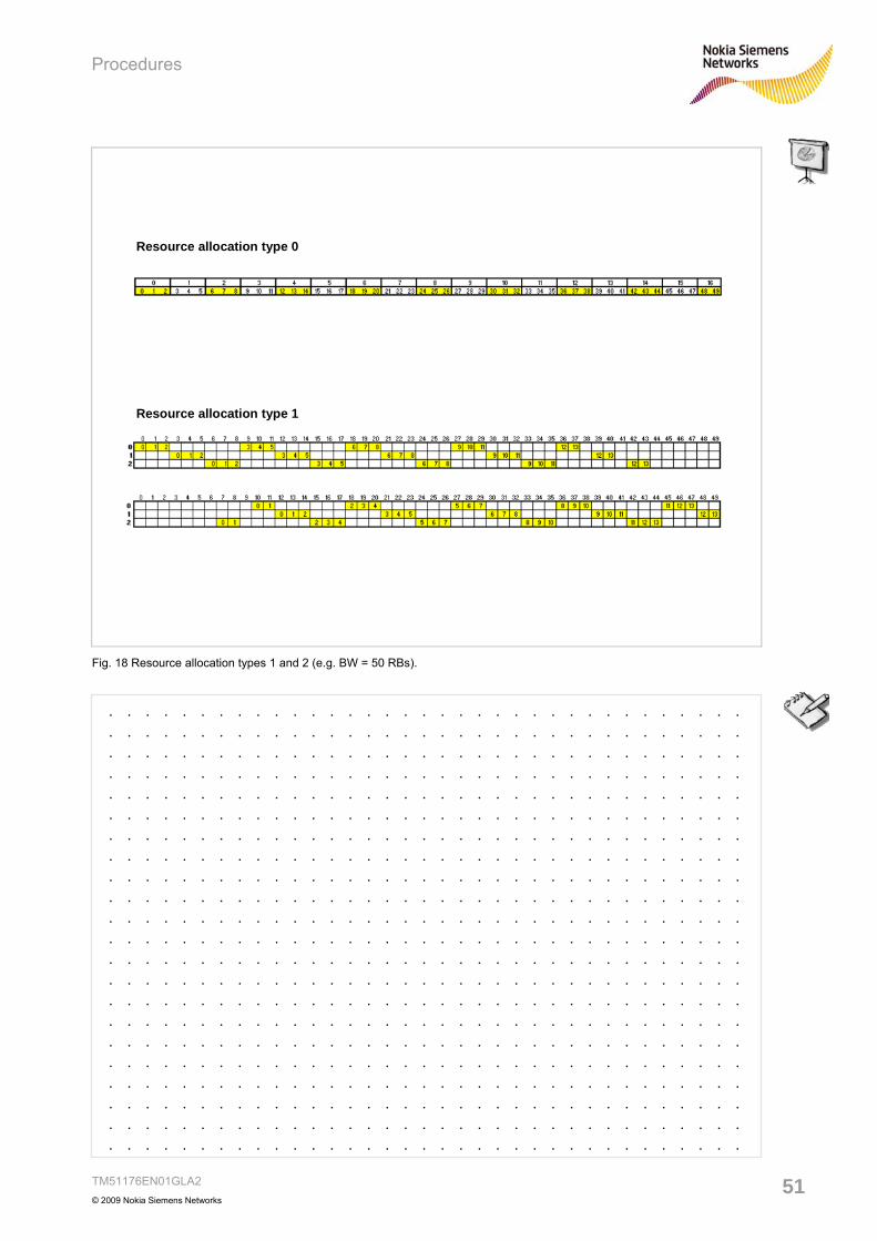
7.1 Resource allocation Three types of allocation are used: type 0: DCI formats 1, 2, 2A type 1: DCI formats 1, 2, 2A type 2: DCI formats1A, 1B, 1C, 1D One bit in the header is indicating if DCI formats 1, 2, 2A are of type 0 or type 1.

Type 0: A number of resource blocks forms a resource block group (RBG). A bitmap indicates which RBG(s) is/are allocated in the corresponding TTI. I.e. a group-wise addressing of resources is used. The number of PRBs per group (RBG size) P depends on the cell bandwidth - see table. Number of DL RBs P

≤10 1

11 - 26 2

27 - 63 3

64 - 110 4

Table 1: RGB size = f (DL BW).

Example: 50 RBs are grouped into 17 RBGs:16 RBGs of 3 RBs + 1 RBG of 2 PRBs. The LSB addresses the RBG with the 2 RBs of the highest frequencies.

1 1 1 0 0 0 0 0 1 0 1 1 1 0 0 1 1

Type 1: In type 1 allocation P RGB subsets are in use. There are 3 fields in the allocation to address single PRBs of an indicated group. Additionally a resource allocation shift may be applied. Example: 50 PRBs are organized into 3 RBG subsets of 18, 17 and 15 PRBs. The first field indicates the subset, the second field an offset followed by the bitmap MSB..LSB.

1 0 1 0 0 0 0 0 1 0 1 1 1 0 0 1 1

Procedures

TM51176EN01GLA2

© 2009 Nokia Siemens Networks 51

. . . . . . . . . . . . . . . . . . . . . . . . . . . . . . . . . . . . . . . . . . . . . . . . . . . . . . . . . . . . . . . . . . . . . . . . . . . . . . . . . . . . . . . . . . . . . . . . . . . . . . . . . . . . . . . . . . . . . . . . . . . . . . . . . . . . . . . . . . . . . . . . . . . . . . . . . . . . . . . . . . . . . . . . . . . . . . . . . . . . . . . . . . . . . . . . . . . . . . . . . . . . . . . . . . . . . . . . . . . . . . . . . . . . . . . . . . . . . . . . . . . . . . . . . . . . . . . . . . . . . . . . . . . . . . . . . . . . . . . . . . . . . . . . . . . . . . . . . . . . . . . . . . . . . . . . . . . . . . . . . . . . . . . . . . . . . . . . . . . . . . . . . . . . . . . . . . . . . . . . . . . . . . . . . . . . . . . . . . . . . . . . . . . . . . . . . . . . . . . . . . . . . . . . . . . . . . . . . . . . . . . . . . . . . . . . . . . . . . . . . . . . . . . . . . . . . . . . . . . . . . . . . . . . . . . . . . . . . . . . . . . . . . . . . . . . . . . . . . . . . . . . . . . . . . . . . . . . . . . . . . . . . . . . . . . . . . . . . . . . . . . . . . . . . . . . . . . . . . . . . . . . . . . . . . . . . . . . . . . . . . . . . . . . . . . . . . . . . . . . . . . . . . . . . . . . . . . . . . . . . . . . . . . . . . . . . . . . . . . . . . . . . . . . . . . . . . . . . . . . . . . . . . . . . . . . . . . . . . . . . . . . . . . . . . . . . . . . . . . . . . . . . . . . . . . . . . . . . . . . . . . . . . . . . . . . . . . . . . . . . . . . . . . . . . . . . . . . . . . . . . . . . . . . . .

Resource allocation type 0

Resource allocation type 1

Fig. 18 Resource allocation types 1 and 2 (e.g. BW = 50 RBs).

Procedures

TM51176EN01GLA2© 2009 Nokia Siemens Networks

52

Type 2: Contiguous allocations are made by type 2. The virtual RBs are localized or distributed. In case of 1A, 1B or 1D the distributed version is signaled by a flag where for 1C this is always the case. Applicable bandwidths: - localized: 1 VRB .. system BW - 1A distributed: 1 .. N_VRB if P-RNTI, RA-RNTI or SI-RNTI scrambled. - 1B, 1D or 1A distributed, C-RNTI scrambled:1 :: N_VRB (BW = 6 .. 49) and 1 .. 16 (BW = 50..110). - 1C : N_step .. floor(N_VRB / N_step) * N_step. N_step = 2 (BW = 6..49), = 4 (BW=50 .. 100).

7.2 Modulation and TB size A 5-bit "modulation and coding scheme" yields the modulation order, i.e. QPSK, 16QAM or 64QAM. Implicitly the coding rate is given by a combination of the number of scheduled RBs and the signaled TB size.

Procedures

TM51176EN01GLA2

© 2009 Nokia Siemens Networks 53

. . . . . . . . . . . . . . . . . . . . . . . . . . . . . . . . . . . . . . . . . . . . . . . . . . . . . . . . . . . . . . . . . . . . . . . . . . . . . . . . . . . . . . . . . . . . . . . . . . . . . . . . . . . . . . . . . . . . . . . . . . . . . . . . . . . . . . . . . . . . . . . . . . . . . . . . . . . . . . . . . . . . . . . . . . . . . . . . . . . . . . . . . . . . . . . . . . . . . . . . . . . . . . . . . . . . . . . . . . . . . . . . . . . . . . . . . . . . . . . . . . . . . . . . . . . . . . . . . . . . . . . . . . . . . . . . . . . . . . . . . . . . . . . . . . . . . . . . . . . . . . . . . . . . . . . . . . . . . . . . . . . . . . . . . . . . . . . . . . . . . . . . . . . . . . . . . . . . . . . . . . . . . . . . . . . . . . . . . . . . . . . . . . . . . . . . . . . . . . . . . . . . . . . . . . . . . . . . . . . . . . . . . . . . . . . . . . . . . . . . . . . . . . . . . . . . . . . . . . . . . . . . . . . . . . . . . . . . . . . . . . . . . . . . . . . . . . . . . . . . . . . . . . . . . . . . . . . . . . . . . . . . . . . . . . . . . . . . . . . . . . . . . . . . . . . . . . . . . . . . . . . . . . . . . . . . . . . . . . . . . . . . . . . . . . . . . . . . . . . . . . . . . . . . . . . . . . . . . . . . . . . . . . . . . . . . . . . . . . . . . . . . . . . . . . . . . . . . . . . . . . . . . . . . . . . . . . . . . . . . . . . . . . . . . . . . . . . . . . . . . . . . . . . . . . . . . . . . . . . . . . . . . . . . . . . . . . . . . . . . . . . . . . . . . . . . . . . . . . . . . . . . . . . . . .

0

20

40

60

80

100

120

0 5 10 15 20 25 30

MCS index

code

rate

/ %

a) code rate vs MCS and b) code rate vs number of PRBs

a) Examples for- 2 symbols for signalling (dashed)- 3 symbols for signalling (solid)- NPRB=8

b) Examples for- MCS = 28- MCS = 14- MCS = 0- 2 symbols for signalling

0

10

20

30

40

50

60

70

80

90

100

0 10 20 30 40 50 60 70 80 90 100 110

number of PRBs

code

rate

/ %

constant:- two antenna ports

- single transport block case Fig. 19 Code rate dependencies for different MCS ids and variable number of PRBs.

Procedures

TM51176EN01GLA2© 2009 Nokia Siemens Networks

54

The determination is based on the signaled MCS Index IMCS.

MCS Index Modulation Order TBS Index

I MCS Q m I TBS 0 2 0 1 2 1 2 2 2 3 2 3 4 2 4 5 2 5 6 2 6 7 2 7 8 2 8 9 2 9

10 4 9 11 4 10 12 4 11 13 4 12 14 4 13 15 4 14 16 4 15 17 6 15 18 6 16 19 6 17 20 6 18 21 6 19 22 6 20 23 6 21 24 6 22 25 6 23 26 6 24 27 6 25 28 6 26 29 2 30 4 31 6

reserved

Table 2: Modulation and TBS index table for PDSCH.

By means of a 27x110 table the resulting TB size can be determined. Part of the table (for non two-layer spatial multiplex) is shown in the figure. A graphical display is shown below. Note, for two-layer spatial multiplex additionally a translation table has to be applied. In case of DCI format 1C a separate table is used.

Procedures

TM51176EN01GLA2

© 2009 Nokia Siemens Networks 55

. . . . . . . . . . . . . . . . . . . . . . . . . . . . . . . . . . . . . . . . . . . . . . . . . . . . . . . . . . . . . . . . . . . . . . . . . . . . . . . . . . . . . . . . . . . . . . . . . . . . . . . . . . . . . . . . . . . . . . . . . . . . . . . . . . . . . . . . . . . . . . . . . . . . . . . . . . . . . . . . . . . . . . . . . . . . . . . . . . . . . . . . . . . . . . . . . . . . . . . . . . . . . . . . . . . . . . . . . . . . . . . . . . . . . . . . . . . . . . . . . . . . . . . . . . . . . . . . . . . . . . . . . . . . . . . . . . . . . . . . . . . . . . . . . . . . . . . . . . . . . . . . . . . . . . . . . . . . . . . . . . . . . . . . . . . . . . . . . . . . . . . . . . . . . . . . . . . . . . . . . . . . . . . . . . . . . . . . . . . . . . . . . . . . . . . . . . . . . . . . . . . . . . . . . . . . . . . . . . . . . . . . . . . . . . . . . . . . . . . . . . . . . . . . . . . . . . . . . . . . . . . . . . . . . . . . . . . . . . . . . . . . . . . . . . . . . . . . . . . . . . . . . . . . . . . . . . . . . . . . . . . . . . . . . . . . . . . . . . . . . . . . . . . . . . . . . . . . . . . . . . . . . . . . . . . . . . . . . . . . . . . . . . . . . . . . . . . . . . . . . . . . . . . . . . . . . . . . . . . . . . . . . . . . . . . . . . . . . . . . . . . . . . . . . . . . . . . . . . . . . . . . . . . . . . . . . . . . . . . . . . . . . . . . . . . . . . . . . . . . . . . . . . . . . . . . . . . . . . . . . . . . . . . . . . . . . . . . . . . . . . . . . . . . . . . . . . . . . . . . . . . . . . . . . . . . . . . . . . . . . . . . . . . . . . . . . . . . . . . . . . . . .

Fig. 20 Part of the table of TB size as function of MCS index and PRB number (non – two-layer spatial multiplex case).

Procedures

TM51176EN01GLA2© 2009 Nokia Siemens Networks

56

7.3 CQI, PMI and RI reporting The UE is requested to send either periodic or a periodic reports concerning • rank indication (RI) Reports are applicable for closed- and open-loop spatial multiplexing. In case of open-loop TRI=1 corresponds to transmit diversity and TRI>1 to large delay CDD. • precoding matrix indicator (PMI) PMI reporting is relevant for spatial multiplexing (open- and closed-loop), MU-MIMO, closed-loop RANK=1 precoding. PMI and RI are confined to a subset of the codebook which is created by means of a codebookSubsetRestriction parameter. • channel quality indication (CQI) CQI may be wideband or may be related to subbands. Similar to HSPA the CQI definition is targeted at 10 % BLER whereby the overall energy per bit is nearly minimized. For the purpose of periodic reporting the PUCCH is utilized, a periodic reports are sent on the PUSCH. The latter reports are explicitly requested by setting the CQI request field in connection with an uplink grant. In case of "collision" the aperiodic report will be transmitted. Furthermore the scheduling mode can be frequency non-selective (periodic) or frequency selective (periodic and aperiodic). The offset is signaled by nomPDSCH-RS-EPRE-Offset.

Procedures

TM51176EN01GLA2

© 2009 Nokia Siemens Networks 57

. . . . . . . . . . . . . . . . . . . . . . . . . . . . . . . . . . . . . . . . . . . . . . . . . . . . . . . . . . . . . . . . . . . . . . . . . . . . . . . . . . . . . . . . . . . . . . . . . . . . . . . . . . . . . . . . . . . . . . . . . . . . . . . . . . . . . . . . . . . . . . . . . . . . . . . . . . . . . . . . . . . . . . . . . . . . . . . . . . . . . . . . . . . . . . . . . . . . . . . . . . . . . . . . . . . . . . . . . . . . . . . . . . . . . . . . . . . . . . . . . . . . . . . . . . . . . . . . . . . . . . . . . . . . . . . . . . . . . . . . . . . . . . . . . . . . . . . . . . . . . . . . . . . . . . . . . . . . . . . . . . . . . . . . . . . . . . . . . . . . . . . . . . . . . . . . . . . . . . . . . . . . . . . . . . . . . . . . . . . . . . . . . . . . . . . . . . . . . . . . . . . . . . . . . . . . . . . . . . . . . . . . . . . . . . . . . . . . . . . . . . . . . . . . . . . . . . . . . . . . . . . . . . . . . . . . . . . . . . . . . . . . . . . . . . . . . . . . . . . . . . . . . . . . . . . . . . . . . . . . . . . . . . . . . . . . . . . . . . . . . . . . . . . . . . . . . . . . . . . . . . . . . . . . . . . . . . . . . . . . . . . . . . . . . . . . . . . . . . . . . . . . . . . . . . . . . . . . . . . . . . . . . . . . . . . . . . . . . . . . . . . . . . . . . . . . . . . . . . . . . . . . . . . . . . . . . . . . . . . . . . . . . . . . . . . . . . . . . . . . . . . . . . . . . . . . . . . . . . . . . . . . . . . . . . . . . . . . . . . . . . . . . . . . . . . . . . . . . . . . . . . . . . . . . . . . . . . . . . . . . . . . . . . . . . . . . . . . . . . . . . . . .

4-bit CQI Table

0

1

2

3

4

5

6

0 1 2 3 4 5 6 7 8 9 10 11 12 13 14 15

CQI index

effic

ienc

y

0

10

20

30

40

50

60

70

80

90

100

0 1 2 3 4 5 6 7 8 9 10 11 12 13 14 15

CQI index

code

rate

/ %

Fig. 21 CQI mapping.

Procedures

TM51176EN01GLA2© 2009 Nokia Siemens Networks

58

Procedures

TM51176EN01GLA2

© 2009 Nokia Siemens Networks 59

8 HARQ

Procedures

TM51176EN01GLA2© 2009 Nokia Siemens Networks

60

Hybrid ARQ (HARQ) leads to higher efficiency in transmission and error correction. There is one HARQ entity per UE with 8 stop-and-wait processes for each HARQ entity. Both incremental redundancy and chase combining are supported. The number of HARQ retransmissions targeted by the HARQ protocol depends on the network configuration. The BLER seen by RLC is much lower than the BLER seen by the HARQ protocol. As an example, the HARQ protocol could be operated in a very persistent manner to avoid RLC retransmissions as far as possible. If a radio block fails due to the CRC evaluation, a retransmission is issued. L1 is used for signaling to indicate need for retransmission, a fast round trip time is facilitated between UE and BTS. But rather than erasing the failed bits they will remain in the soft memory buffer of the UE and are used to enhance detection of the retransmitted bits.

Procedures

TM51176EN01GLA2

© 2009 Nokia Siemens Networks 61

. . . . . . . . . . . . . . . . . . . . . . . . . . . . . . . . . . . . . . . . . . . . . . . . . . . . . . . . . . . . . . . . . . . . . . . . . . . . . . . . . . . . . . . . . . . . . . . . . . . . . . . . . . . . . . . . . . . . . . . . . . . . . . . . . . . . . . . . . . . . . . . . . . . . . . . . . . . . . . . . . . . . . . . . . . . . . . . . . . . . . . . . . . . . . . . . . . . . . . . . . . . . . . . . . . . . . . . . . . . . . . . . . . . . . . . . . . . . . . . . . . . . . . . . . . . . . . . . . . . . . . . . . . . . . . . . . . . . . . . . . . . . . . . . . . . . . . . . . . . . . . . . . . . . . . . . . . . . . . . . . . . . . . . . . . . . . . . . . . . . . . . . . . . . . . . . . . . . . . . . . . . . . . . . . . . . . . . . . . . . . . . . . . . . . . . . . . . . . . . . . . . . . . . . . . . . . . . . . . . . . . . . . . . . . . . . . . . . . . . . . . . . . . . . . . . . . . . . . . . . . . . . . . . . . . . . . . . . . . . . . . . . . . . . . . . . . . . . . . . . . . . . . . . . . . . . . . . . . . . . . . . . . . . . . . . . . . . . . . . . . . . . . . . . . . . . . . . . . . . . . . . . . . . . . . . . . . . . . . . . . . . . . . . . . . . . . . . . . . . . . . . . . . . . . . . . . . . . . . . . . . . . . . . . . . . . . . . . . . . . . . . . . . . . . . . . . . . . . . . . . . . . .

DL: asynchronous

UL: synchronous

HARQ: 8 stop-and-wait processes (UL & DL)

Fig. 22 Asynchronous and synchronous HARQ (UL and DL).

Procedures

TM51176EN01GLA2© 2009 Nokia Siemens Networks

62

The lower part of the MAC entity is the HARQ (Hybrid Automatic Retransmission on reQuest) entity. Note that only certain transport channel types can have this unit. The assembled transport block from the multiplexer will be stored in one of the HARQ’s buffers and simultaneously sent to the physical layer: • If the eNB/UE receives the transport block correctly, it will send an ACK indication

via a special physical channel. This would delete the transport channel from the buffer.

• If no indication or a NACK indication is received, the HARQ entity will retransmit

the transport block. Both, UL and DL HARQ are based on an N-stop-and-wait processes. A main difference between HARQ in UL and DL: • UL: a synchronous mode is used • DL deploys an adaptive, asynchronous HARQ.

Procedures

TM51176EN01GLA2

© 2009 Nokia Siemens Networks 63

. . . . . . . . . . . . . . . . . . . . . . . . . . . . . . . . . . . . . . . . . . . . . . . . . . . . . . . . . . . . . . . . . . . . . . . . . . . . . . . . . . . . . . . . . . . . . . . . . . . . . . . . . . . . . . . . . . . . . . . . . . . . . . . . . . . . . . . . . . . . . . . . . . . . . . . . . . . . . . . . . . . . . . . . . . . . . . . . . . . . . . . . . . . . . . . . . . . . . . . . . . . . . . . . . . . . . . . . . . . . . . . . . . . . . . . . . . . . . . . . . . . . . . . . . . . . . . . . . . . . . . . . . . . . . . . . . . . . . . . . . . . . . . . . . . . . . . . . . . . . . . . . . . . . . . . . . . . . . . . . . . . . . . . . . . . . . . . . . . . . . . . . . . . . . . . . . . . . . . . . . . . . . . . . . . . . . . . . . . . . . . . . . . . . . . . . . . . . . . . . . . . . . . . . . . . . . . . . . . . . . . . . . . . . . . . . . . . . . . . . . . . . . . . . . . . . . . . . . . . . . . . . . . . . . . . . . . . . . . . . . . . . . . . . . . . . . . . . . . . . . . . . . . . . . . . . . . . . . . . . . . . . . . . . . . . . . . . . . . . . . . . . . . . . . . . . . . . . . . . . . . . . . . . . . . . . . . . . . . . . . . . . . . . . . . . . . . . . . . . . . . . . . . . . . . . . . . . . . . . . . . . . . . . . . . . . . . . . . . . . . . . . . . . . . . . . . . . . . . . . . . . . . . . . . . . . . . . . . . . . . . . . . . . . . . . . . . . . . . . . . . . . . . . . . . . . . . . . . . . . . . . . . . . . . . . . . . . . . . . . . . . . . . . . . . . . . . . . . . . . . . . . . . . . . .

HARQ - soft combining principle

Tx

0 1 2 3

DPSCH

DPCCH

NACK

Redundancy versions

Fig. 23 HARQ -soft combining.

Procedures

TM51176EN01GLA2© 2009 Nokia Siemens Networks

64


Recommended