Report No: 06BL042-RF-CE-P17V02 Page : 1 of 28 Version:1.0 Test Report Product Name MEGA BOOK Model No. MS-1311,S300,MS-1715,MS-1715B,L745,MS-1716,MS-1716B, L740,MS-1057,MS-1057B,S262,S262B,SIM2060 Applicant MICRO-STAR INTL Co., LTD. Address No. 69, Li-De St., Jung-He City, Taipei Hsien, Taiwan, R.O.C. Date of Receipt Nov. 03, 2006 Issued Date Dec. 04, 2006 Report No. 06BL042-RF-CE-P17V02 The test results relate only to the samples tested. The test report shall not be reproduced except in full without the written approval of QuieTek Corporation.
Transcript
Report No: 06BL042-RF-CE-P17V02
Page : 1 of 28 Version:1.0
Test Report
Product Name MEGA BOOK
Model No. MS-1311,S300,MS-1715,MS-1715B,L745,MS-1716,MS-1716B,
The test results relate only to the samples tested. The test report shall not be reproduced except in full without the written approval of QuieTek Corporation.
Report No: 06BL042-RF-CE-P17V02
Page : 2 of 28 Version:1.0
Test Report Cert i f icat ion Issued Date : Dec. 04, 2006 Report No. : 06BL042-RF-CE-P17V02
Model No. MS-1311,S300,MS-1715,MS-1715B,L745,MS-1716,MS-1716B,L740,MS-1057,
MS-1057B,S262,S262B,SIM2060
Rated Voltage AC 230V/50Hz
Working Voltage AC 230V/50Hz
Trade Name MSI
Applicable
Standard
ETSI EN 300 328:V1.6.1 (2004-11)
Test Result Complied The Test Results relate only to the samples tested. The test report is under the previsions of Directive 1999/5/EC, Article 3.2. The test report shall not be reproduced except in full without the written approval of QuieTek Corporation.
Documented By :
( D e m i C h a n g )
Tested By :
( E r i c L e e )
Approved By :
( R o y W a n g )
0914
Report No: 06BL042-RF-CE-P17V02
Page : 3 of 28 Version:1.0
TABLE OF CONTENTS Description Page 1. GENERAL INFORMATION............................................................................................................4 1.1. EUT Description............................................................................................................................4 1.2. Tested System Details....................................................................................................................6 1.3. Configuration of Test System........................................................................................................6 1.4. EUT Exercise Software .................................................................................................................6 1.5. Test Facility ...................................................................................................................................7 2. Equivalent Isotropic Radiated Power ..............................................................................................8 2.1. Test Equipment..............................................................................................................................8 2.2. Test Setup ......................................................................................................................................8 2.3. Test Condition ...............................................................................................................................8 2.4. Limits ............................................................................................................................................8 2.5. Test Procedure ...............................................................................................................................9 2.6. Test Specification ..........................................................................................................................9 2.7. Uncertainty ....................................................................................................................................9 2.8. Test Result .....................................................................................................................................9 3. Frequency Range .............................................................................................................................10 3.1. Test Equipment............................................................................................................................10 3.2. Test Setup ....................................................................................................................................10 3.3. Test Condition .............................................................................................................................10 3.4. Limits ..........................................................................................................................................10 3.5. Test Procedure .............................................................................................................................11 3.6. Test Specification ........................................................................................................................11 3.7. Uncertainty ..................................................................................................................................11 3.8. Test Result ...................................................................................................................................11 4. Spurious Emission............................................................................................................................12 4.1. Test Equipment............................................................................................................................12 4.2. Test Setup ....................................................................................................................................13 4.3. Test Condition .............................................................................................................................13 4.4. Limits ..........................................................................................................................................13 4.5. Test Procedure .............................................................................................................................14 4.6. Test Specification ........................................................................................................................14 4.7. Uncertainty ..................................................................................................................................14 4.8. Test Result ...................................................................................................................................14 5. Measurement Uncertainty Values ..................................................................................................15 6. EMC Reduction Method During Compliance Testing..................................................................16 7. Test Result.........................................................................................................................................17 7.1. Test Data of Equivalent Isotropic Radiated Power......................................................................18 7.2. Test Data of Frequency Range ....................................................................................................19 7.3. Test Data of Spurious Emission ..................................................................................................20 Attachment 1: EUT Test Photographs Attachment 2: EUT Detailed Photographs Reference : Laboratory of License
Report No: 06BL042-RF-CE-P17V02
Page : 4 of 28 Version:1.0
1. GENERAL INFORMATION
1.1. EUT Description
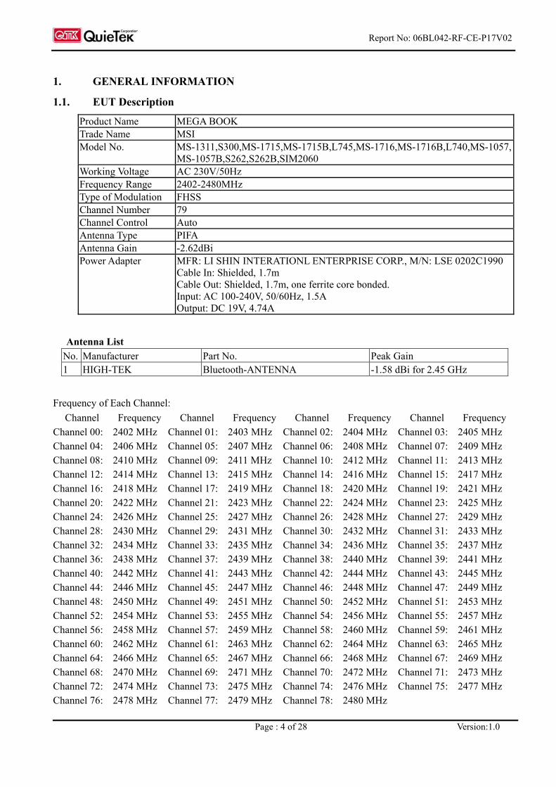
Product Name MEGA BOOK Trade Name MSI Model No. MS-1311,S300,MS-1715,MS-1715B,L745,MS-1716,MS-1716B,L740,MS-1057,
MS-1057B,S262,S262B,SIM2060 Working Voltage AC 230V/50Hz Frequency Range 2402-2480MHz Type of Modulation FHSS Channel Number 79 Channel Control Auto Antenna Type PIFA Antenna Gain -2.62dBi Power Adapter MFR: LI SHIN INTERATIONL ENTERPRISE CORP., M/N: LSE 0202C1990
Cable In: Shielded, 1.7m Cable Out: Shielded, 1.7m, one ferrite core bonded. Input: AC 100-240V, 50/60Hz, 1.5A Output: DC 19V, 4.74A
Antenna List
No. Manufacturer Part No. Peak Gain 1 HIGH-TEK Bluetooth-ANTENNA -1.58 dBi for 2.45 GHz
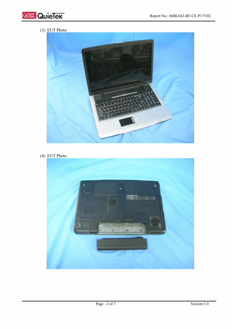
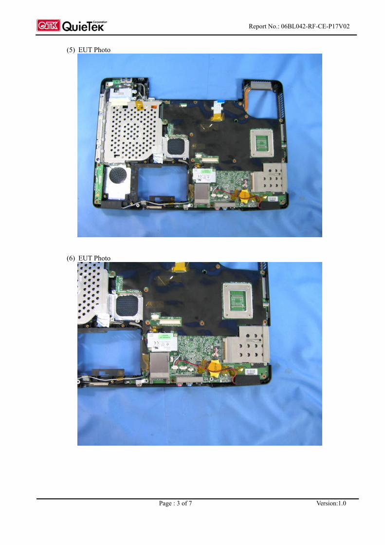
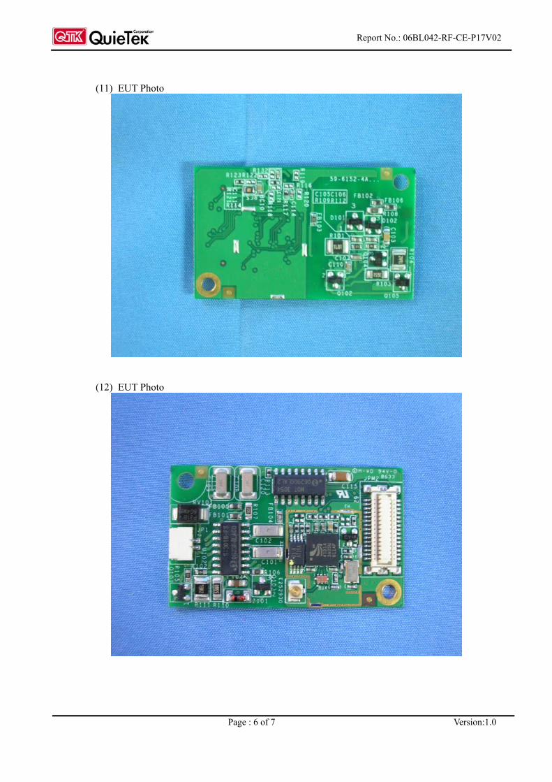
1. The EUT is a MEGA BOOK with a built-in 2.4GHz transceiver.
2. The variation of model number is for different strategy of marketing.
3. Regarding to the frequency band, at least two channels are selected to perform the test.
4. This device is a composite device in according to ETSI regulations.
5. QuieTek verified the construction and function in typical operation. All the test modes were carried out
with the EUT in normal operation, which was shown in this test report and defined as:
Mode 1: Transmit Mode 2: Receive
Report No: 06BL042-RF-CE-P17V02
Page : 6 of 28 Version:1.0
1.2. Tested System Details
The types for all equipment, plus descriptions of all cables used in the tested system (including inserted cards) are:
N/A
1.3. Configuration of Test System
EUT
1.4. EUT Exercise Software
(1) Setup the EUT as shown in Section 1.4.
(2) Execute the BlueTest (v1.9.1) program on the notebook.
(3) Configure the test channel and the packet type.
(4) Press “OK” to start the continuous transmission/receiving.
(5) Verify the EUT operation properly.
Report No: 06BL042-RF-CE-P17V02
Page : 7 of 28 Version:1.0
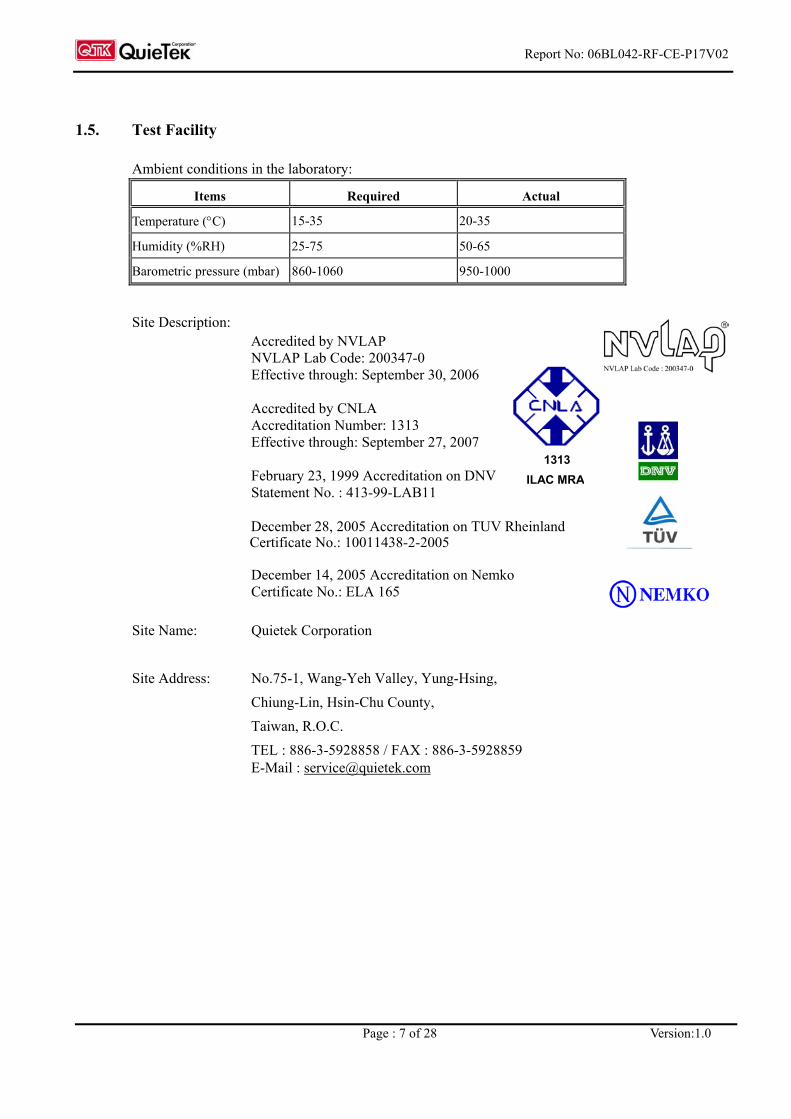
1.5. Test Facility
Ambient conditions in the laboratory:
Items Required Actual
Temperature (°C) 15-35 20-35
Humidity (%RH) 25-75 50-65
Barometric pressure (mbar) 860-1060 950-1000
Site Description: Accredited by NVLAP NVLAP Lab Code: 200347-0 Effective through: September 30, 2006 Accredited by CNLA Accreditation Number: 1313 Effective through: September 27, 2007
February 23, 1999 Accreditation on DNV
Statement No. : 413-99-LAB11
December 28, 2005 Accreditation on TUV Rheinland Certificate No.: 10011438-2-2005
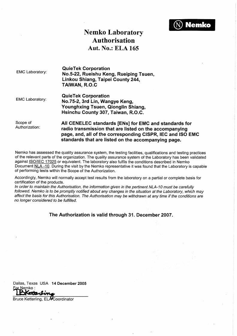
December 14, 2005 Accreditation on Nemko Certificate No.: ELA 165 Site Name: Quietek Corporation Site Address: No.75-1, Wang-Yeh Valley, Yung-Hsing, Chiung-Lin, Hsin-Chu County, Taiwan, R.O.C. TEL : 886-3-5928858 / FAX : 886-3-5928859 E-Mail : [email protected]
1313 ILAC MRA
Report No: 06BL042-RF-CE-P17V02
Page : 8 of 28 Version:1.0
2. Equivalent Isotropic Radiated Power
2.1. Test Equipment
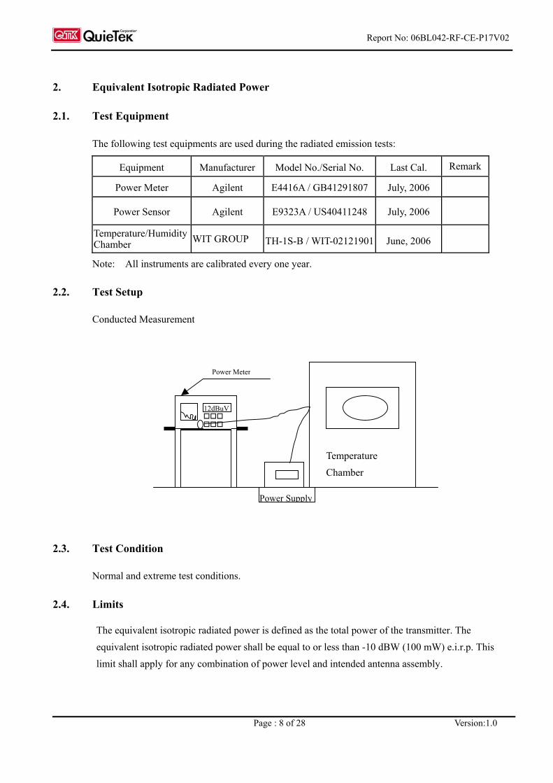
The following test equipments are used during the radiated emission tests:
Equipment Manufacturer Model No./Serial No. Last Cal. Remark
Power Meter Agilent E4416A / GB41291807 July, 2006
Power Sensor Agilent E9323A / US40411248 July, 2006
Temperature/Humidity Chamber WIT GROUP TH-1S-B / WIT-02121901 June, 2006
Note: All instruments are calibrated every one year.
2.2. Test Setup
Conducted Measurement
2.3. Test Condition
Normal and extreme test conditions.
2.4. Limits
The equivalent isotropic radiated power is defined as the total power of the transmitter. The equivalent isotropic radiated power shall be equal to or less than -10 dBW (100 mW) e.i.r.p. This limit shall apply for any combination of power level and intended antenna assembly.
Power Meter
12dBuV
Temperature Chamber
Power Supply
Report No: 06BL042-RF-CE-P17V02
Page : 9 of 28 Version:1.0
2.5. Test Procedure
Step 1: - using a suitable means, the output of the transmitter shall be coupled to a matched diode detector; - the output of the diode detector shall be connected to the vertical channel of an oscilloscope; - the combination of the diode detector and the oscilloscope shall be capable of faithfully
reproducing the envelope peaks and the duty cycle of the transmitter output signal; - the observed duty cycle of the transmitter (Tx on/(Tx on + Tx off)) shall be noted as x, (0 < x < 1)
and recorded. For the purpose of testing, the equipment shall be operated with a duty cycle that is equal to or more than 0.1.
Step 2: - the average output power of the transmitter shall be determined using a wideband, calibrated RF
power meter with a matched thermocouple detector or an equivalent thereof and, where applicable, with an integration period that exceeds the repetition period of the transmitter by a factor 5 or more. The observed value shall be recorded as "A" (in dBm);
- the e.i.r.p. shall be calculated from the above measured power output A, the observed duty cycle x, and the applicable antenna assembly gain "G" in dBi, according to the formula: P = A + G + 10 log (1/x); P shall not exceed the value specified in clause 2.4.
The measurement shall be repeated at the lowest, the middle, and the highest frequency of the stated frequency range. These frequencies shall be recorded. FHSS equipment shall be made to hop continuously to each of these three frequencies separately.
2.6. Test Specification
According to ETSI EN 300 328:V1.6.1 (2004-11)
2.7. Uncertainty
± 1.27dB
2.8. Test Result
The test data is shown in Section 8. The EUT complies the specified limits and passes the test.
Report No: 06BL042-RF-CE-P17V02
Page : 10 of 28 Version:1.0
Spectrum Analyzar
3. Frequency Range
3.1. Test Equipment
Equipment Manufacturer Model No./Serial No. Last Cal. Remark
Spectrum Analyzer R&S FSP / 100561 Mar., 2006 STANDARD TEMPERATURE & HUMIDITY
WIT TH-1S-B / 108210 Nov., 2006
Note: All Instruments are calibrated every one year.
3.2. Test Setup
Conducted Measurement
3.3. Test Condition
Normal and extreme test conditions.
3.4. Limits
The frequency range of the equipment is determined by the lowest and highest frequencies occupied by the power envelope. fH is the highest frequency of the power envelope: it is the frequency furthest above the frequency of maximum power where the output power drops below the level of -80 dBm/Hz e.i.r.p. spectral power density (-30 dBm if measured in a100 kHz bandwidth). fL is the lowest frequency of the power envelope; it is the frequency furthest below the frequency of maximum power where the output power drops below the level equivalent to -80 dBm/Hz e.i.r.p. spectral power density (or -30 dBm if measured in a 100 kHz bandwidth).
12dBuV
Temperature Chamber
Power Supply
Report No: 06BL042-RF-CE-P17V02
Page : 11 of 28 Version:1.0
3.5. Test Procedure
a) Place the spectrum analyzer in video averaging mode with a minimum of 50 sweeps selected and activate the transmitter with modulation applied. The RF emission of the equipment shall be displayed on the spectrum analyzer;
b) Select lowest operating frequency of the equipment under test; c) Using the marker of the spectrum analyzer, find lowest frequency below the operating frequency
at which spectral power density drops below the level given in clause 4.4. This frequency shall be recorded;
d) Select the highest operating frequency of the equipment under test; e) Find the highest frequency at which the spectral power density drops below the value given in
clause 4.4. This frequency shall be recorded; f) The difference between the frequencies measured in steps c) and e) is the frequency range.
3.6. Test Specification
According to ETSI EN 300 328:V1.6.1 (2004-11)
3.7. Uncertainty
The measurement uncertainty is defined as ± 100 kHz
3.8. Test Result
The test data is shown in Section 8. The EUT complies the specified limits and passes the test.
Report No: 06BL042-RF-CE-P17V02
Page : 12 of 28 Version:1.0
4. Spurious Emission
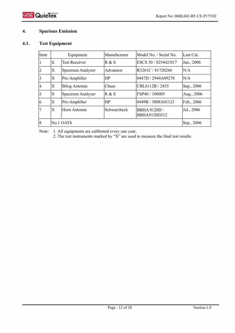
4.1. Test Equipment
Item Equipment Manufacturer Model No. / Serial No. Last Cal.
1 X Test Receiver R & S ESCS 30 / 825442/017 Jan., 2006
2 X Spectrum Analyzer Advantest R3261C / 81720266 N/A
3 X Pre-Amplifier HP 8447D / 2944A09276 N/A
4 X Bilog Antenna Chase CBL6112B / 2455 Sep., 2006
5 X Spectrum Analyzer R & S FSP40 / 100005 Aug., 2006
6 X Pre-Amplifier HP 8449B / 3008A01123 Feb., 2006
7 X Horn Antenna Schwarzbeck BBHA 9120D / BBHA9120D312
Jul., 2006
8 No.1 OATS Sep., 2006
Note: 1. All equipments are calibrated every one year. 2. The test instruments marked by “X” are used to measure the final test results.
Report No: 06BL042-RF-CE-P17V02
Page : 13 of 28 Version:1.0
4.2. Test Setup
4.3. Test Condition
Standard Temperature and Humidity, Standard Test Voltage
4.4. Limits
Transmitter limits for narrowband spurious emission
Frequency Range Limit when operating Limit when in standby
30MHzto 1 GHz -36 dBm -57 dBm
Above 1 GHz to 12.75 GHz -30 dBm -47 dBm 1.8 GHz to 1.9 GHz
5.15 GHz to 5.3 GHz -47 dBm -47 dBm
Transmitter limits for wideband spurious emission
Frequency Range Limit when operating Limit when in standby
30MHzto 1 GHz -86 dBm/Hz -107 dBm/Hz
Above 1 GHz to 12.75 GHz -80 dBm/Hz -97 dBm/Hz 1.8 GHz to 1.9 GHz
5.15 GHz to 5.3 GHz -97 dBm/Hz -97 dBm/Hz
EUT
FRP Dome
Test Receiver
Antenna Mast Bilog or Horn Antenna Antenna height can be moved from 1m to 4m, Antenna and turntable distance 3m
TO ControllerTo Receiver
Fully Soldered Ground Plane
Non-Conducted Table
3m
1m to 4m
1.5 m
Load
Report No: 06BL042-RF-CE-P17V02
Page : 14 of 28 Version:1.0
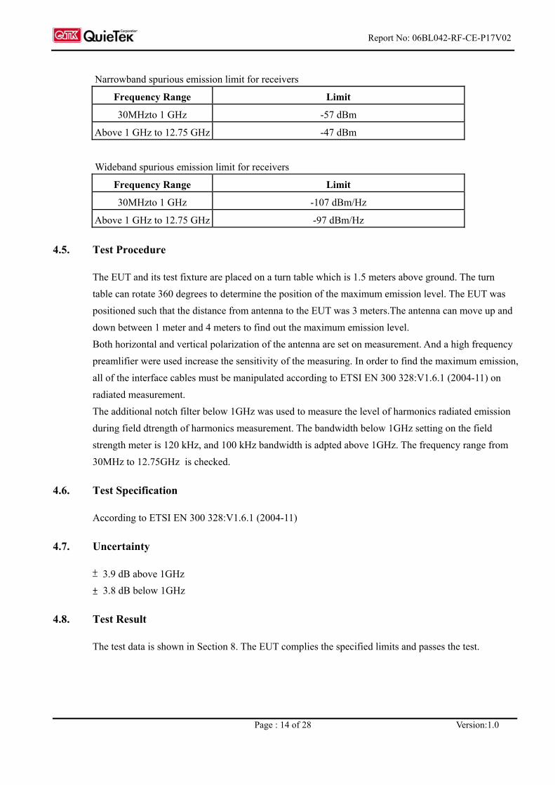
Narrowband spurious emission limit for receivers
Frequency Range Limit
30MHzto 1 GHz -57 dBm
Above 1 GHz to 12.75 GHz -47 dBm
Wideband spurious emission limit for receivers
Frequency Range Limit
30MHzto 1 GHz -107 dBm/Hz
Above 1 GHz to 12.75 GHz -97 dBm/Hz
4.5. Test Procedure
The EUT and its test fixture are placed on a turn table which is 1.5 meters above ground. The turn table can rotate 360 degrees to determine the position of the maximum emission level. The EUT was positioned such that the distance from antenna to the EUT was 3 meters.The antenna can move up and down between 1 meter and 4 meters to find out the maximum emission level. Both horizontal and vertical polarization of the antenna are set on measurement. And a high frequency preamlifier were used increase the sensitivity of the measuring. In order to find the maximum emission, all of the interface cables must be manipulated according to ETSI EN 300 328:V1.6.1 (2004-11) on radiated measurement. The additional notch filter below 1GHz was used to measure the level of harmonics radiated emission during field dtrength of harmonics measurement. The bandwidth below 1GHz setting on the field strength meter is 120 kHz, and 100 kHz bandwidth is adpted above 1GHz. The frequency range from 30MHz to 12.75GHz is checked.
4.6. Test Specification
According to ETSI EN 300 328:V1.6.1 (2004-11)
4.7. Uncertainty
± 3.9 dB above 1GHz ± 3.8 dB below 1GHz
4.8. Test Result
The test data is shown in Section 8. The EUT complies the specified limits and passes the test.
Report No.: 06BL042-RF-CE-P17V02
Page : 15 of 28 Version:1.0
5. Measurement Uncertainty Values
The maximum values of the absolute measurement uncertainties of the measurements defined in the present document shall not exceed the values given below:
Parameter Uncertainty
Radio frequency 1 x10 –5
Total RF power, conducted 1.5 dB
RF power density, conducted 3 dB
Spurious emissions, conducted 3 dB
All emissions, radiated 6 dB
Temperature 1oC
Humidity 5 %
DC and low frequency voltages 3 %
For the measurement methods according to the present document these uncertainty figures are valid to a confidence level of 95 % calculated according to the methods described in ETR 028 [5], on guidelines for estimating uncertainties in measuring methods.
Report No.: 06BL042-RF-CE-P17V02
Page : 16 of 28 Version:1.0
6. EMC Reduction Method During Compliance Testing
No modification was made during testing.
Report No.: 06BL042-RF-CE-P17V02
Page : 17 of 28 Version:1.0
7. Test Result
The test results in the emission and the immunity were performed according to the requirements of measurement standard and process. Quietek Corporation is assumed full responsibility for the accuracy and completeness of these measurements. The test data of the emission is listed as below. All the tests were carried out with the EUT in normal operation, which was defined as:
EMI Mode Mode 1: Transmit
Mode 2: Receive
Report No.: 06BL042-RF-CE-P17V02
Page : 18 of 28 Version:1.0
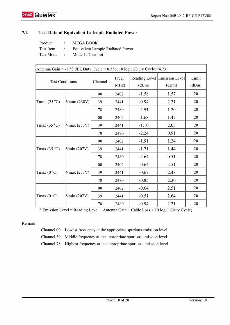
7.1. Test Data of Equivalent Isotropic Radiated Power
Product : MEGA BOOK Test Item : Equivalent Istropic Radiated Power Test Mode : Mode 1: Transmit
Channel 00 Lowest frequency at the appropriate spurious emission level Channel 39 Middle frequency at the appropriate spurious emission level Channel 78 Highest frequency at the appropriate spurious emission level
Report No.: 06BL042-RF-CE-P17V02
Page : 19 of 28 Version:1.0
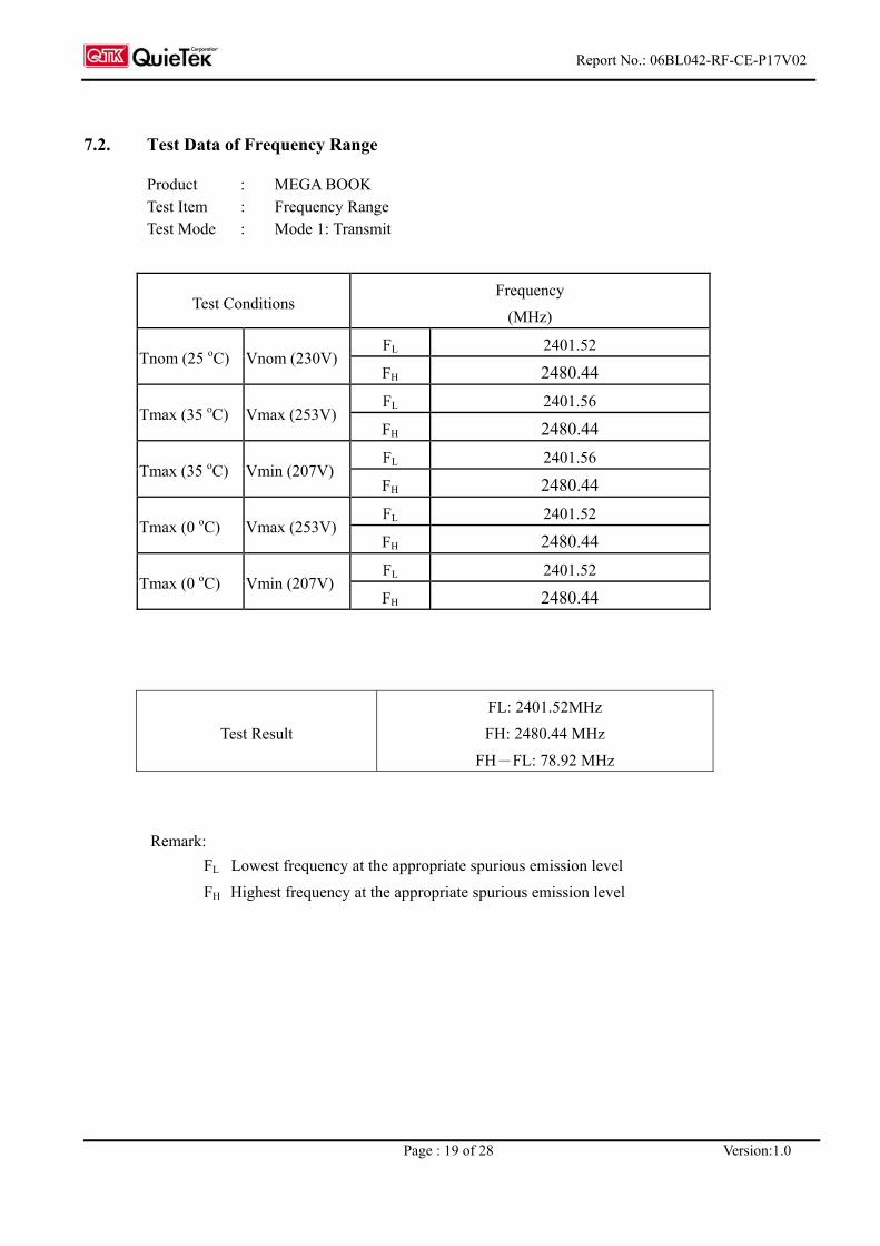
7.2. Test Data of Frequency Range
Product : MEGA BOOK Test Item : Frequency Range Test Mode : Mode 1: Transmit
Test Conditions Frequency
(MHz)
FL 2401.52 Tnom (25 oC) Vnom (230V)
FH 2480.44 FL 2401.56
Tmax (35 oC) Vmax (253V) FH 2480.44 FL 2401.56
Tmax (35 oC) Vmin (207V) FH 2480.44 FL 2401.52
Tmax (0 oC) Vmax (253V) FH 2480.44 FL 2401.52
Tmax (0 oC) Vmin (207V) FH 2480.44
Test Result FL: 2401.52MHz FH: 2480.44 MHz
FH-FL: 78.92 MHz
Remark: FL Lowest frequency at the appropriate spurious emission level
FH Highest frequency at the appropriate spurious emission level
Report No.: 06BL042-RF-CE-P17V02
Page : 20 of 28 Version:1.0
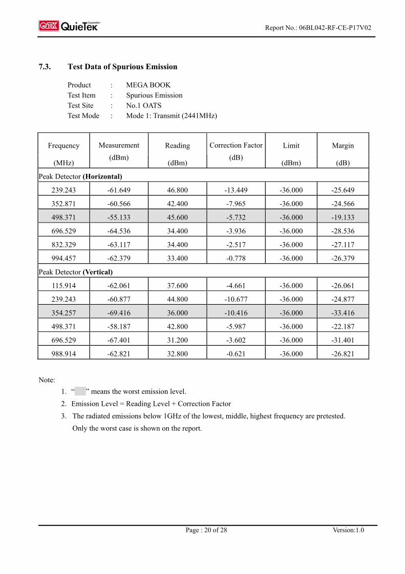
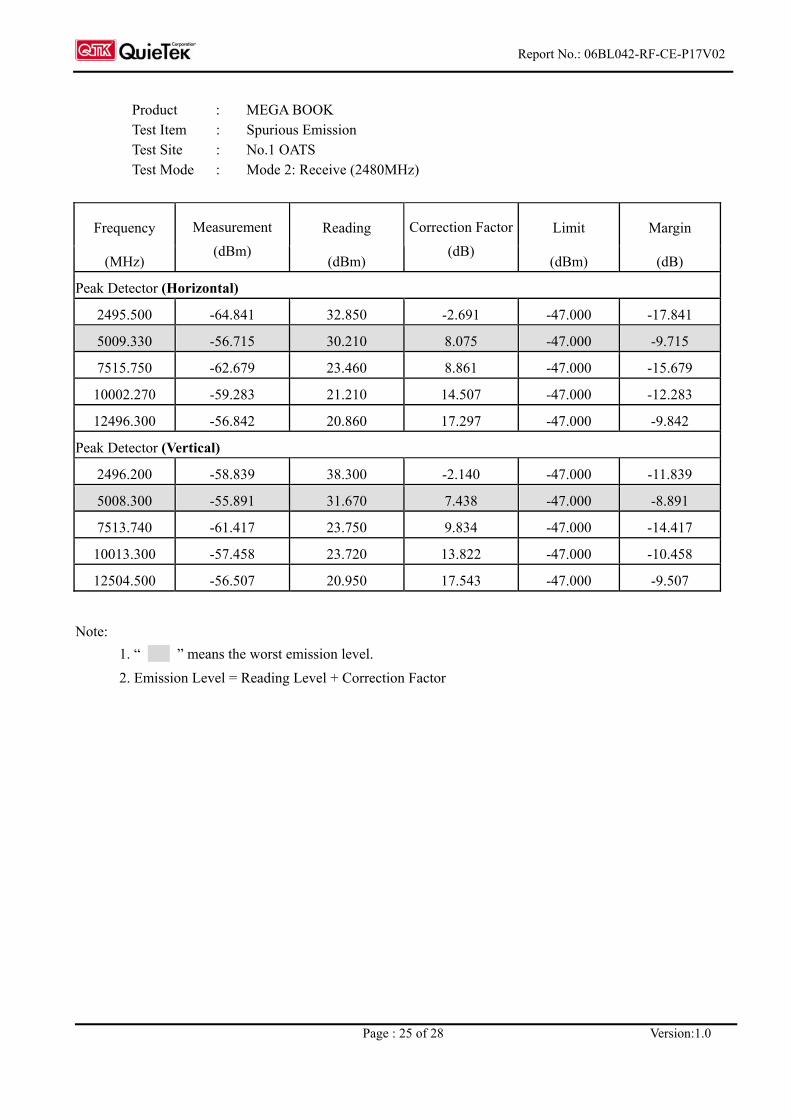
7.3. Test Data of Spurious Emission
Product : MEGA BOOK Test Item : Spurious Emission Test Site : No.1 OATS Test Mode : Mode 1: Transmit (2441MHz)
Frequency Reading Limit Margin
(MHz)
Measurement (dBm)
(dBm)
Correction Factor (dB)
(dBm) (dB)
Peak Detector (Horizontal)
239.243 -61.649 46.800 -13.449 -36.000 -25.649
352.871 -60.566 42.400 -7.965 -36.000 -24.566
498.371 -55.133 45.600 -5.732 -36.000 -19.133
696.529 -64.536 34.400 -3.936 -36.000 -28.536
832.329 -63.117 34.400 -2.517 -36.000 -27.117
994.457 -62.379 33.400 -0.778 -36.000 -26.379
Peak Detector (Vertical)
115.914 -62.061 37.600 -4.661 -36.000 -26.061
239.243 -60.877 44.800 -10.677 -36.000 -24.877
354.257 -69.416 36.000 -10.416 -36.000 -33.416
498.371 -58.187 42.800 -5.987 -36.000 -22.187
696.529 -67.401 31.200 -3.602 -36.000 -31.401
988.914 -62.821 32.800 -0.621 -36.000 -26.821
Note: 1. “ ” means the worst emission level.
2. Emission Level = Reading Level + Correction Factor 3. The radiated emissions below 1GHz of the lowest, middle, highest frequency are pretested.
Only the worst case is shown on the report.
Report No.: 06BL042-RF-CE-P17V02
Page : 21 of 28 Version:1.0
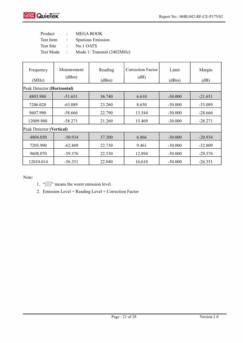
Product : MEGA BOOK Test Item : Spurious Emission Test Site : No.1 OATS Test Mode : Mode 1: Transmit (2402MHz)
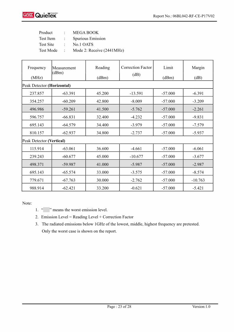
Product : MEGA BOOK Test Item : Spurious Emission Test Site : No.1 OATS Test Mode : Mode 2: Receive (2441MHz)
Frequency Reading Limit Margin
(MHz)
Measurement (dBm)
(dBm)
Correction Factor (dB)
(dBm) (dB)
Peak Detector (Horizontal)
237.857 -63.391 45.200 -13.591 -57.000 -6.391
354.257 -60.209 42.800 -8.009 -57.000 -3.209
496.986 -59.261 41.500 -5.762 -57.000 -2.261
596.757 -66.831 32.400 -4.232 -57.000 -9.831
695.143 -64.579 34.400 -3.979 -57.000 -7.579
810.157 -62.937 34.800 -2.737 -57.000 -5.937
Peak Detector (Vertical)
115.914 -63.061 36.600 -4.661 -57.000 -6.061
239.243 -60.677 45.000 -10.677 -57.000 -3.677
498.371 -59.987 41.000 -5.987 -57.000 -2.987
695.143 -65.574 33.000 -3.575 -57.000 -8.574
779.671 -67.763 30.000 -2.762 -57.000 -10.763
988.914 -62.421 33.200 -0.621 -57.000 -5.421
Note: 1. “ ” means the worst emission level. 2. Emission Level = Reading Level + Correction Factor 3. The radiated emissions below 1GHz of the lowest, middle, highest frequency are pretested.
Only the worst case is shown on the report.
Report No.: 06BL042-RF-CE-P17V02
Page : 24 of 28 Version:1.0
Product : MEGA BOOK Test Item : Spurious Emission Test Site : No.1 OATS Test Mode : Mode 2: Receive (2402MHz)
Frequency Reading Limit Margin
(MHz)
Measurement (dBm)
(dBm)
Correction Factor (dB)
(dBm) (dB)
Peak Detector (Horizontal)
2400.500 -58.055 39.840 -2.894 -47.000 -11.055
4801.010 -64.453 23.960 6.586 -47.000 -17.453
7201.490 -63.45 22.900 8.650 -47.000 -16.450
9602.010 -59.8 21.670 13.530 -47.000 -12.800
12002.540 -59.058 20.500 15.442 -47.000 -12.058
Peak Detector (Vertical)
2400.500 -58.242 39.030 -2.272 -47.000 -11.242
4800.990 -64.365 23.780 6.855 -47.000 -17.365
7201.500 -63.214 22.330 9.456 -47.000 -16.214
9602.000 -60.37 21.750 12.880 -47.000 -13.370
12002.500 -58.174 20.230 16.596 -47.000 -11.174
Note: 1. “ ” means this data is the worst emission level.