41
Department of EEE Friday, July 13, 2012 V .J.I.T - Dept of EEE
| Date post: | 05-Apr-2018 |
| Category: |
Documents |
| Upload: | venky123456789 |
| View: | 218 times |
| Download: | 0 times |

7/31/2019 07915a0204-hvdc
http://slidepdf.com/reader/full/07915a0204-hvdc 1/41
Department of EEE
Friday, July 13, 2012 V.J.I.T - Dept of EEE

7/31/2019 07915a0204-hvdc
http://slidepdf.com/reader/full/07915a0204-hvdc 2/41
Electrical engg technicalseminar
Friday, July 13, 2012 V.J.I.T - Dept of EEE
Krishna . K EEE B07915A0204

7/31/2019 07915a0204-hvdc
http://slidepdf.com/reader/full/07915a0204-hvdc 3/41
HVDC LIGHT, A TOOLFOR TRANSMISSION OFELECTRIC POWER
Friday, July 13, 2012 V.J.I.T - Dept of EEE
7/31/2019 07915a0204-hvdc
http://slidepdf.com/reader/full/07915a0204-hvdc 4/41
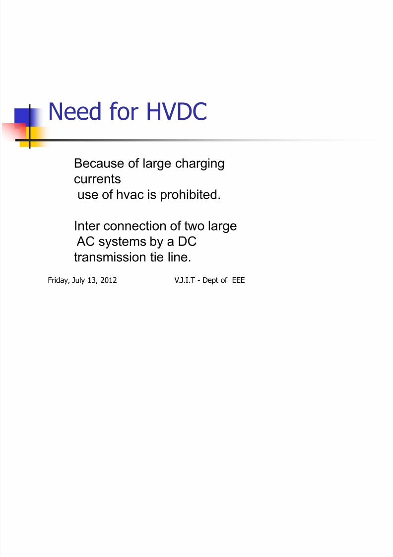
Need for HVDC
Friday, July 13, 2012 V.J.I.T - Dept of EEE
Because of large charging
currents
use of hvac is prohibited.
Inter connection of two large
AC systems by a DC
transmission tie line.

7/31/2019 07915a0204-hvdc
http://slidepdf.com/reader/full/07915a0204-hvdc 5/41
CONTENTS INTRODUCTION
HVDC LIGHT CONVERTER STATION
HVDC CABLES CONTROL OF ACTIVE AND REACTIVE POWER
FEATURES OF HVDC LIGHT
APPLICATIONS
CONVERTER CONTROL AND PROTECTION CONCLUSION
REFERENCES
Friday, July 13, 2012 V.J.I.T - Dept of EEE
7/31/2019 07915a0204-hvdc
http://slidepdf.com/reader/full/07915a0204-hvdc 6/41
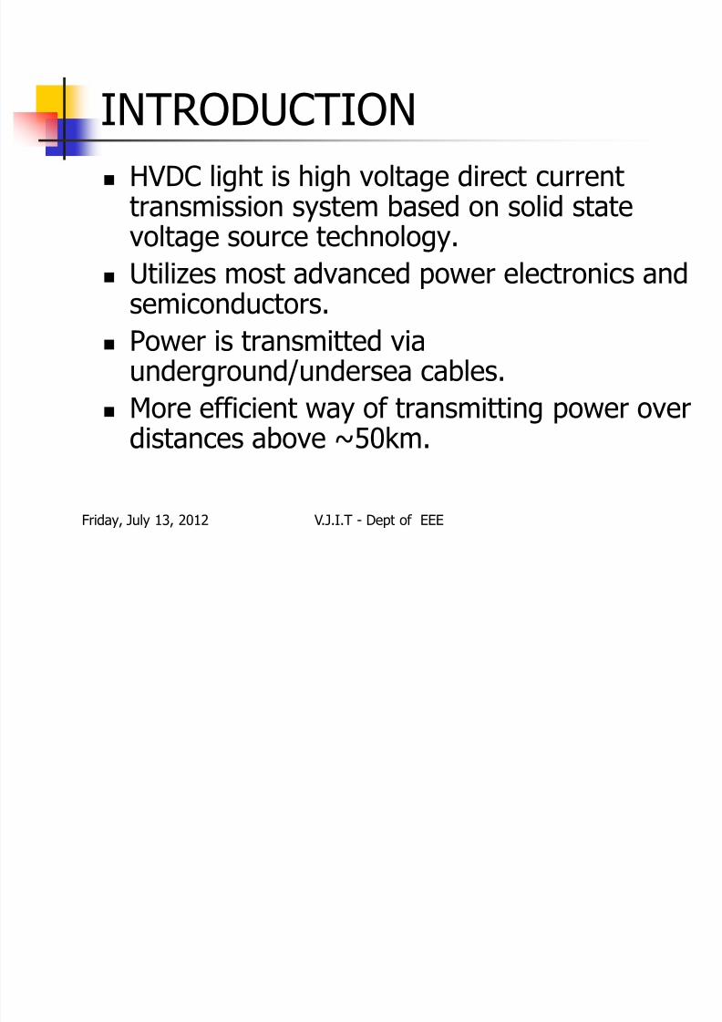
INTRODUCTION HVDC light is high voltage direct current
transmission system based on solid statevoltage source technology.
Utilizes most advanced power electronics andsemiconductors.
Power is transmitted via
underground/undersea cables. More efficient way of transmitting power over
distances above ~50km.
Friday, July 13, 2012 V.J.I.T - Dept of EEE
7/31/2019 07915a0204-hvdc
http://slidepdf.com/reader/full/07915a0204-hvdc 7/41
HVDC light installations
Friday, July 13, 2012 V.J.I.T - Dept of EEE
7/31/2019 07915a0204-hvdc
http://slidepdf.com/reader/full/07915a0204-hvdc 8/41Friday, July 13, 2012 V.J.I.T - Dept of EEE

7/31/2019 07915a0204-hvdc
http://slidepdf.com/reader/full/07915a0204-hvdc 9/41
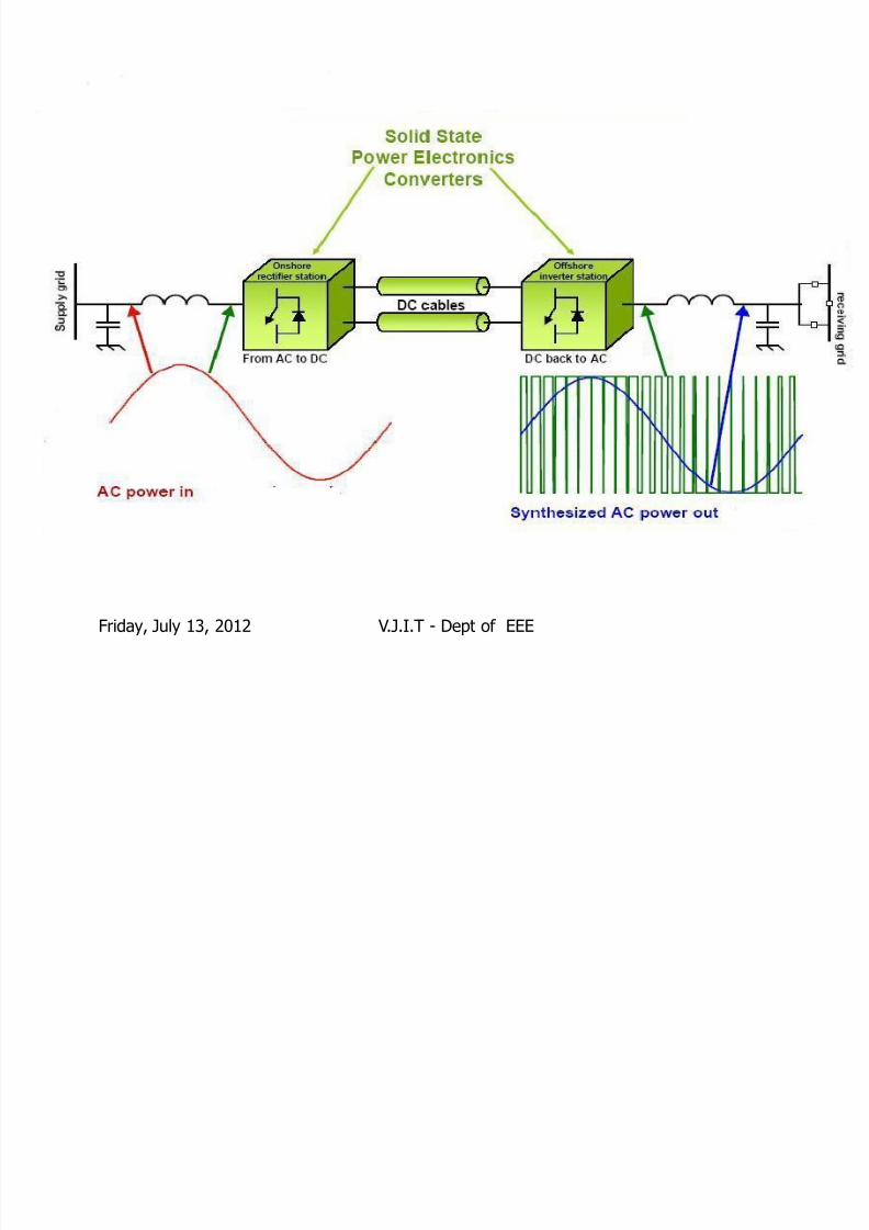
HVDC light converter station
Friday, July 13, 2012 V.J.I.T - Dept of EEE

7/31/2019 07915a0204-hvdc
http://slidepdf.com/reader/full/07915a0204-hvdc 10/41
Power transformer The transformer is an ordinary single phase or three
phase with a tap changer on the secondary side
The filter bus voltage will be controlled with the tap
changer to achieve the maximum active and reactivepower from the converter
The current in the transformer winding containshardly any harmonics and is not exposed to any dc
voltage The transformer may be provided with a tertiary
winding to feed the station auxiliary power system
Friday, July 13, 2012 V.J.I.T - Dept of EEE

7/31/2019 07915a0204-hvdc
http://slidepdf.com/reader/full/07915a0204-hvdc 11/41
Converter reactors
Friday, July 13, 2012 V.J.I.T - Dept of EEE
7/31/2019 07915a0204-hvdc
http://slidepdf.com/reader/full/07915a0204-hvdc 12/41
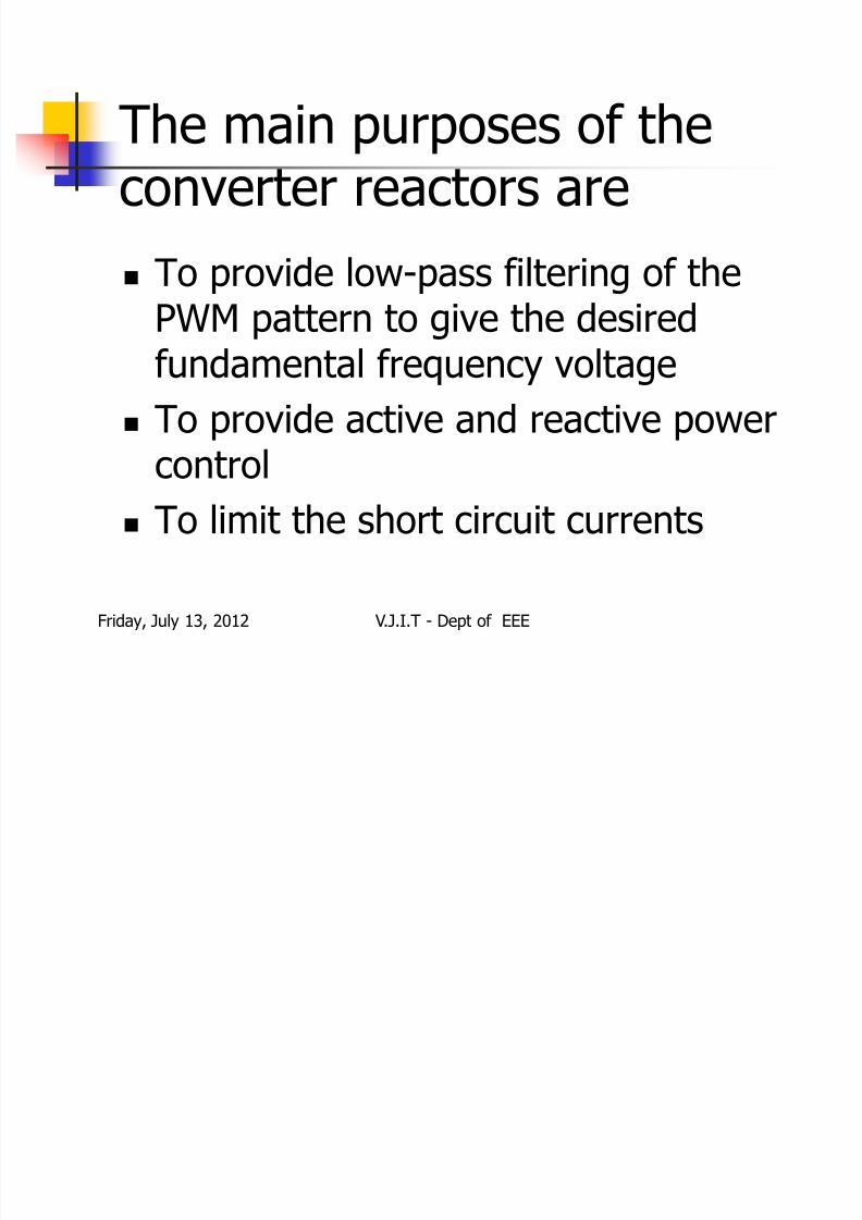
The main purposes of theconverter reactors are
To provide low-pass filtering of thePWM pattern to give the desiredfundamental frequency voltage
To provide active and reactive power
control
To limit the short circuit currents
Friday, July 13, 2012 V.J.I.T - Dept of EEE

7/31/2019 07915a0204-hvdc
http://slidepdf.com/reader/full/07915a0204-hvdc 13/41
DC capacitors The primary objective of the valve dc side
capacitor is to provide a low inductance path
for the turned off current and also to serve asan energy store
It reduces the harmonic ripple on the directvoltage
The ability to limit the dc voltage variationscaused by the disturbances in the systemdepends on the size of the dc side capacitor
Friday, July 13, 2012 V.J.I.T - Dept of EEE
7/31/2019 07915a0204-hvdc
http://slidepdf.com/reader/full/07915a0204-hvdc 14/41
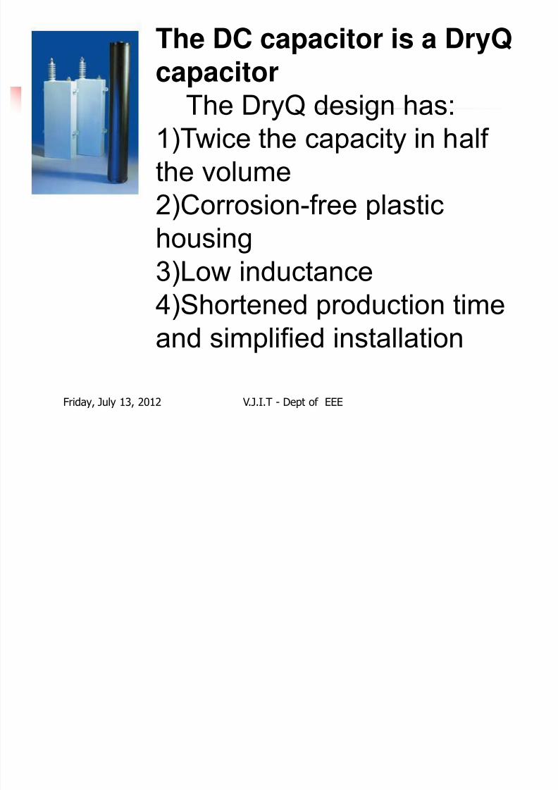
The DC capacitor is a DryQ
capacitor
The DryQ design has:1)Twice the capacity in half
the volume
2)Corrosion-free plastichousing
3)Low inductance
4)Shortened production time
and simplified installation
Friday, July 13, 2012 V.J.I.T - Dept of EEE
7/31/2019 07915a0204-hvdc
http://slidepdf.com/reader/full/07915a0204-hvdc 15/41
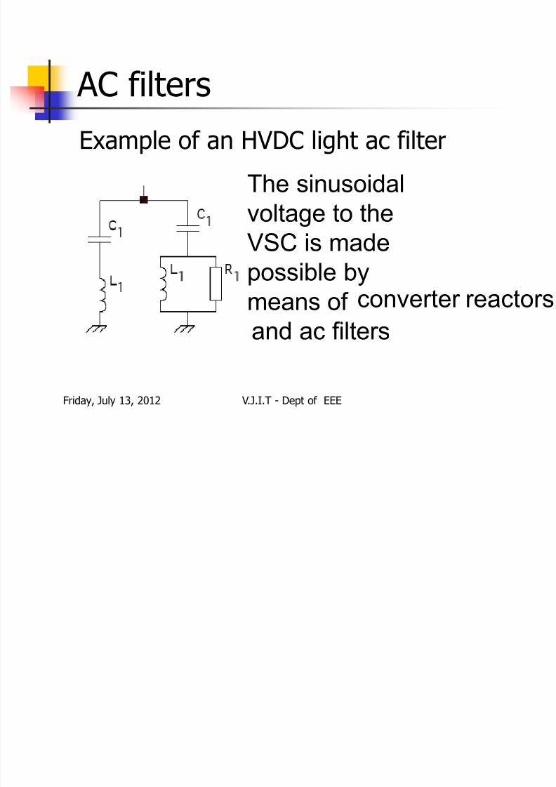
AC filtersExample of an HVDC light ac filter
The sinusoidalvoltage to the
VSC is made
possible by
means of converter reactors
and ac filters
Friday, July 13, 2012 V.J.I.T - Dept of EEE
7/31/2019 07915a0204-hvdc
http://slidepdf.com/reader/full/07915a0204-hvdc 16/41
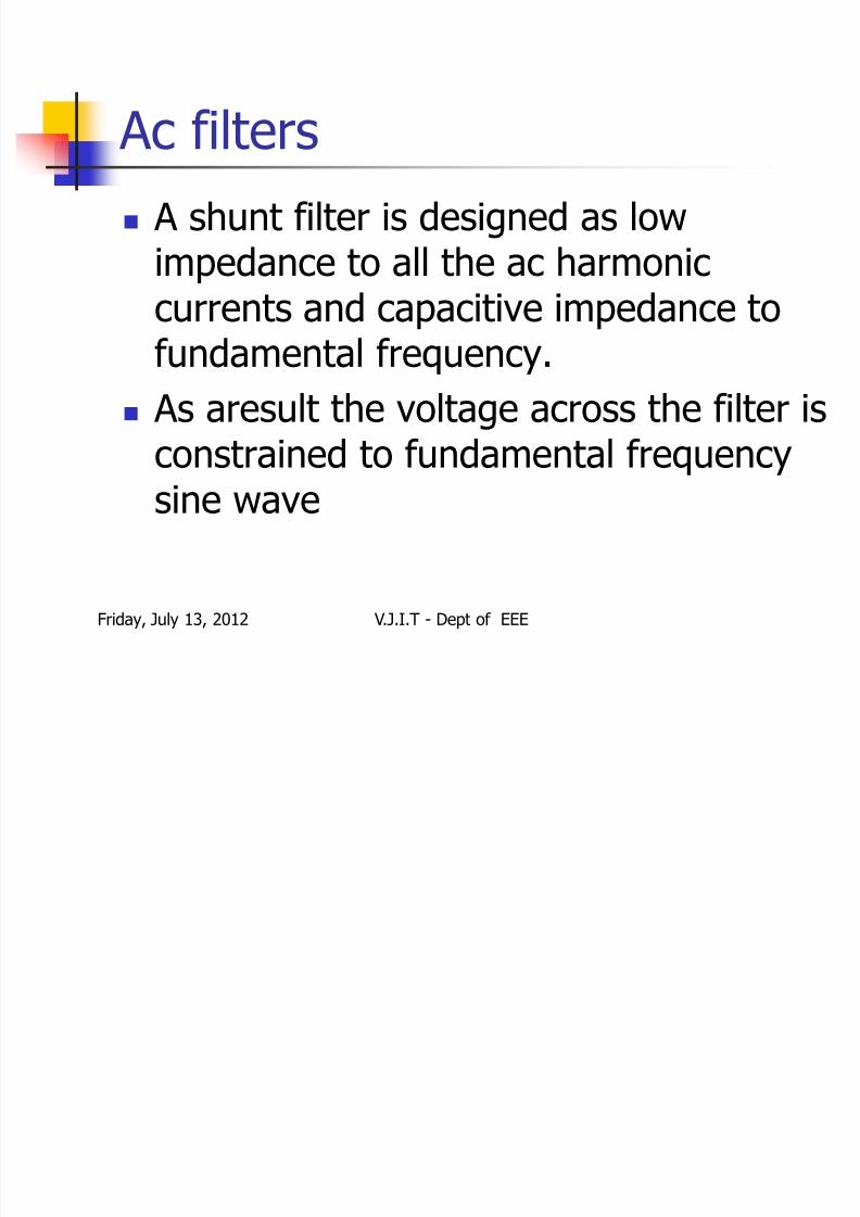
Ac filters A shunt filter is designed as low
impedance to all the ac harmonic
currents and capacitive impedance tofundamental frequency.
As aresult the voltage across the filter is
constrained to fundamental frequencysine wave
Friday, July 13, 2012 V.J.I.T - Dept of EEE
7/31/2019 07915a0204-hvdc
http://slidepdf.com/reader/full/07915a0204-hvdc 17/41
Valves-The IGBT position IGBT is the semiconductor used in
HVDC light
To increase the power handling,sixIGBT chips and three diode chips areconnected in parallel in a sub-module
The IGBT has two,four or six sub-modules, which determine the currentrating of the IGBT
Friday, July 13, 2012 V.J.I.T - Dept of EEE
7/31/2019 07915a0204-hvdc
http://slidepdf.com/reader/full/07915a0204-hvdc 18/41
A complete IGBT position consists of anIGBT,a gate unit,a voltage divider and awater cooled heat sink
The gate driving electronics control the gatevoltage and current at turn on and turn off
The voltage across the IGBT is measured andthe information is sent to the valve control
unit through an optical fibre The voltage divider connected across the
IGBT provides the current needed to drivethe gate
Friday, July 13, 2012 V.J.I.T - Dept of EEE

7/31/2019 07915a0204-hvdc
http://slidepdf.com/reader/full/07915a0204-hvdc 19/41
IGBT with four and six sub-
modules
Friday, July 13, 2012 V.J.I.T - Dept of EEE

7/31/2019 07915a0204-hvdc
http://slidepdf.com/reader/full/07915a0204-hvdc 20/41
Valve function To switch voltages higher than the rated
voltage of one IGBT,several positions are
connected in series in each valve Each IGBT position can be individually
regulated in the valve to the correct voltagelevel
The flexibility of the IGBT makes it possible toblock the current immediately if a short circuitis detected
Friday, July 13, 2012 V.J.I.T - Dept of EEE

7/31/2019 07915a0204-hvdc
http://slidepdf.com/reader/full/07915a0204-hvdc 21/41
Mechanical design of valves
Friday, July 13, 2012 V.J.I.T - Dept of EEE

7/31/2019 07915a0204-hvdc
http://slidepdf.com/reader/full/07915a0204-hvdc 22/41
Valve cooling system
Friday, July 13, 2012 V.J.I.T - Dept of EEE

7/31/2019 07915a0204-hvdc
http://slidepdf.com/reader/full/07915a0204-hvdc 23/41
It consists of water cooled heat sinks whichprovides high efficiency cooling
The water is circulating through the heat sink in close contact with each IGBT,whichefficiently transports the heat away from thesemiconductor
The water passes continuously through a de-ionizing system to keep the conductivity of the water low
Friday, July 13, 2012 V.J.I.T - Dept of EEE

7/31/2019 07915a0204-hvdc
http://slidepdf.com/reader/full/07915a0204-hvdc 24/41
HVDC
Cables
Friday, July 13, 2012 V.J.I.T - Dept of EEE

7/31/2019 07915a0204-hvdc
http://slidepdf.com/reader/full/07915a0204-hvdc 25/41
Advantages of HVDC cables HVDC light cables are installed close in
bipolar pairs with anti parallel currents
and thus eliminating the magnetic fields They have no technical limitation for
distance as in ac cables
Its strength and flexibility makes it wellsuited for several installation conditions
Friday, July 13, 2012 V.J.I.T - Dept of EEE

7/31/2019 07915a0204-hvdc
http://slidepdf.com/reader/full/07915a0204-hvdc 26/41
Control of active and reactive
power
Friday, July 13, 2012 V.J.I.T - Dept of EEE
7/31/2019 07915a0204-hvdc
http://slidepdf.com/reader/full/07915a0204-hvdc 27/41
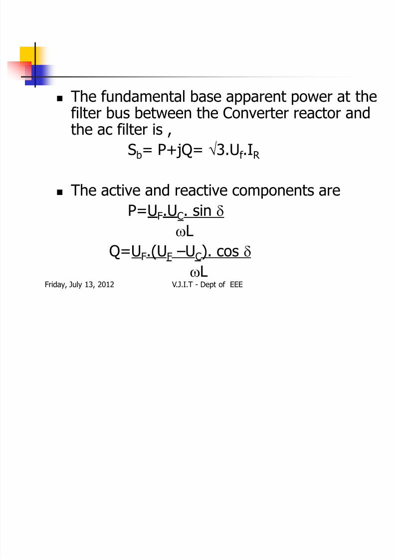
The fundamental base apparent power at thefilter bus between the Converter reactor andthe ac filter is ,
Sb= P+jQ= 3.Uf .IR
The active and reactive components are
P=UF.UC. sin L
Q=UF.(UF –UC). cos
LFriday, July 13, 2012 V.J.I.T - Dept of EEE

7/31/2019 07915a0204-hvdc
http://slidepdf.com/reader/full/07915a0204-hvdc 28/41
Active power flowIf UC is in phase lag,the
active power flows from
ac to dc side(rectifier)
If UC is in phase lead,the
active power flows from
dc to ac side
Friday, July 13, 2012 V.J.I.T - Dept of EEE

7/31/2019 07915a0204-hvdc
http://slidepdf.com/reader/full/07915a0204-hvdc 29/41
Reactive power flow
If UF > UC, there is
reactive power
consumption.
If UC > UF, there is
reactive power
generation.
Friday, July 13, 2012 V.J.I.T - Dept of EEE

7/31/2019 07915a0204-hvdc
http://slidepdf.com/reader/full/07915a0204-hvdc 30/41
Features Independent control of active and reactive
power
Independent power transfer and powerquality control
Power reversal
Reduced power losses in connected ac
systems Increased transfer capacity in the existing
system
Friday, July 13, 2012 V.J.I.T - Dept of EEE

7/31/2019 07915a0204-hvdc
http://slidepdf.com/reader/full/07915a0204-hvdc 31/41
Fast restoration after blackouts
Flexibility in design
No relevant magnetic fields Low environmental impact
Indoor design
Short time schedule
Friday, July 13, 2012 V.J.I.T - Dept of EEE

7/31/2019 07915a0204-hvdc
http://slidepdf.com/reader/full/07915a0204-hvdc 32/41
Kinds of dc links Monopolar lines
Bipolar lines
Homopolar lines Line has one conductor and earth is used
as return conductor(mono)_ve
Line has two conductors one +ve and
one_ve(bipolar) Line have two or more conductor having
same polarity usually _ve
Friday, July 13, 2012 V.J.I.T - Dept of EEE
7/31/2019 07915a0204-hvdc
http://slidepdf.com/reader/full/07915a0204-hvdc 33/41
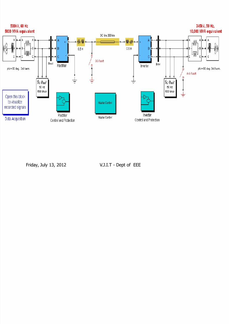
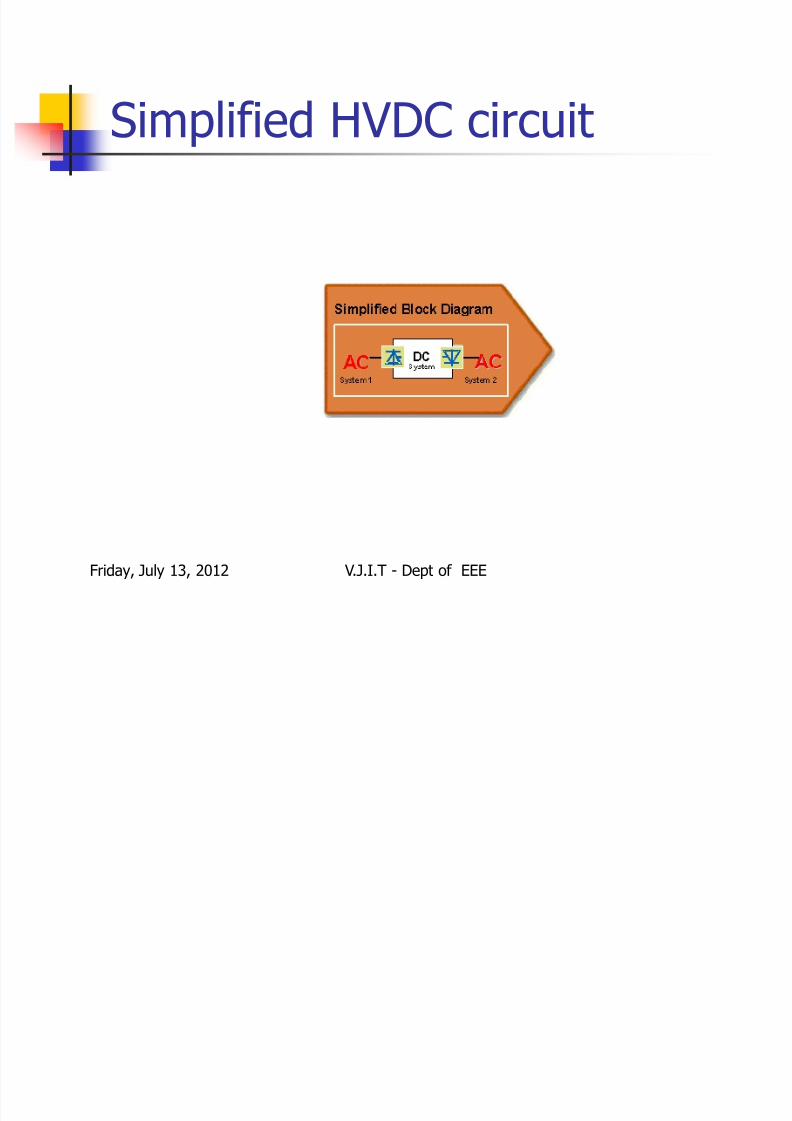
Simplified HVDC circuit
Friday, July 13, 2012 V.J.I.T - Dept of EEE

7/31/2019 07915a0204-hvdc
http://slidepdf.com/reader/full/07915a0204-hvdc 34/41
Dc links
Friday, July 13, 2012 V.J.I.T - Dept of EEE

7/31/2019 07915a0204-hvdc
http://slidepdf.com/reader/full/07915a0204-hvdc 35/41
Ground return It uses t/m lines use ground or sea
water as the return conductor
For the same length of the t/m line theresistance offered by the gnd in case of dc is much less as compared to ac
Earth resistance in case of dc isindependent of line length
Friday, July 13, 2012 V.J.I.T - Dept of EEE

7/31/2019 07915a0204-hvdc
http://slidepdf.com/reader/full/07915a0204-hvdc 36/41
Applications Wind power generation
Multi terminal dc grid
Interconnecting networks
Islanded operation
City infeed
Friday, July 13, 2012 V.J.I.T - Dept of EEE

7/31/2019 07915a0204-hvdc
http://slidepdf.com/reader/full/07915a0204-hvdc 37/41
Reliability and Quality To assure high reliability and availability,the
HVDC light principles include
1.Simple station design 2.Use of components with proven high
reliability
3.Automatic supervision
4.Use of back up control systems andequipment such as measurements,pumps etc
Maintainability
Quality assurance/standardsFriday, July 13, 2012 V.J.I.T - Dept of EEE
7/31/2019 07915a0204-hvdc
http://slidepdf.com/reader/full/07915a0204-hvdc 38/41
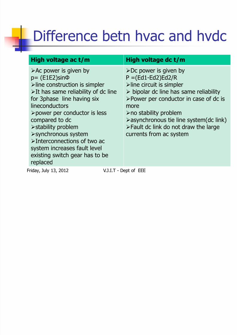
Difference betn hvac and hvdcHigh voltage ac t/m High voltage dc t/m
Ac power is given byp= (E1E2)sinΦ
line construction is simplerIt has same reliability of dc linefor 3phase line having sixlineconductorspower per conductor is lesscompared to dc
stability problemsynchronous systemInterconnections of two acsystem increases fault levelexisting switch gear has to bereplaced
Dc power is given byP =(Ed1-Ed2)Ed2/R
line circuit is simpler bipolar dc line has same reliabilityPower per conductor in case of dc ismoreno stability problemasynchronous tie line system(dc link)
Fault dc link do not draw the largecurrents from ac system
Friday, July 13, 2012 V.J.I.T - Dept of EEE
7/31/2019 07915a0204-hvdc
http://slidepdf.com/reader/full/07915a0204-hvdc 39/41
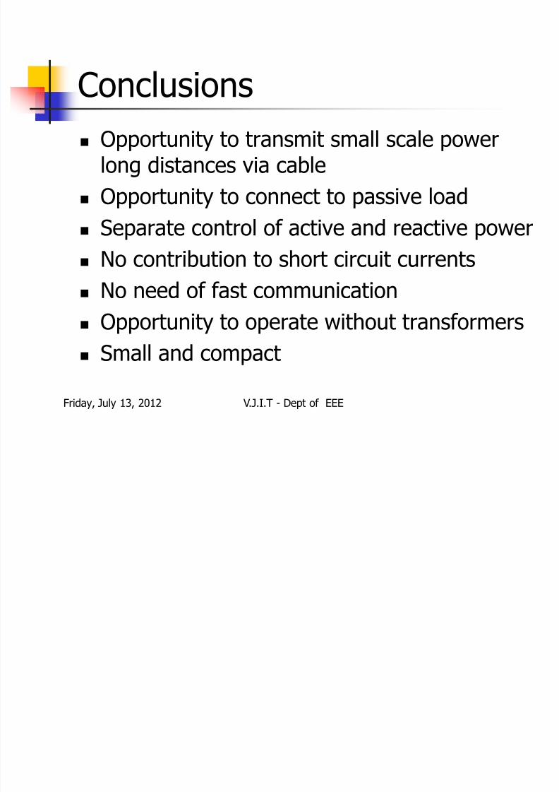
Conclusions Opportunity to transmit small scale power
long distances via cable
Opportunity to connect to passive load Separate control of active and reactive power
No contribution to short circuit currents
No need of fast communication Opportunity to operate without transformers
Small and compact
Friday, July 13, 2012 V.J.I.T - Dept of EEE

7/31/2019 07915a0204-hvdc
http://slidepdf.com/reader/full/07915a0204-hvdc 40/41
References1.DC Transmission based on voltage
source converters,Gunnar Asplund,Kjell
Eriksson and Kjell Svesson,19972.The ABCs of HVDC transmission
technologies,IEEE Power and Energy
Magazine,2006
Friday, July 13, 2012 V.J.I.T - Dept of EEE
7/31/2019 07915a0204-hvdc
http://slidepdf.com/reader/full/07915a0204-hvdc 41/41
Thank you
Krishna. K


