18
DECEMBER 2007 1 08-027r3 Toward SSC Modulation Specs and Link Budget (Spreading the Pain) Guillaume Fortin, Rick Hernandez & Mathieu Gagnon PMC-Sierra

DECEMBER 20071
08-027r3 Toward SSC Modulation Specs and Link Budget
(Spreading the Pain)
Guillaume Fortin, Rick Hernandez & Mathieu GagnonPMC-Sierra

DECEMBER 20072
OverviewOverview
� The JTF as a model of CDR performance� Using the JTF to qualify SSC modulation� Simulation Methodology� Frequency Modulation and Jitter
- Triangular- Hershey Kiss- Square Wave
� Limitation of the JTF as CDR model� Residual SSC Jitter Summary� Value of Residual Jitter From SSC Slope� Tentative Link Budget For Discussion� Tentative SSC Specifications
Note: additions or changes vs. previous version r1 are marked in blue.
DECEMBER 20073
The JTF as a model of CDR performanceThe JTF as a model of CDR performance
� When measuring jitter on the transmitter signal, the main objective should be to verify that this jitter is low enough to guarantee a robust link.
� Applying the jitter transfer function (JTF) on the transmitter jitter removes jitter components.
� The underlying assumption is that the jitter components that are removed do not impact link robustness
- In other words, the JTF represents the assumed performance of a CDR in a SAS-2 system.

DECEMBER 20074
Using the JTF to qualify SSC modulationUsing the JTF to qualify SSC modulation
� Use the JTF to calculate the residual SSC jitter seen by a baseline SAS-2 CDR
� Simulate with worst-case and best-case matlabmodels of the JTF
Worst-case JTF (-72dB @30kHz) Best-case JTF (-75dB @30kHz)
DECEMBER 20075
Simulation MethodologySimulation Methodology
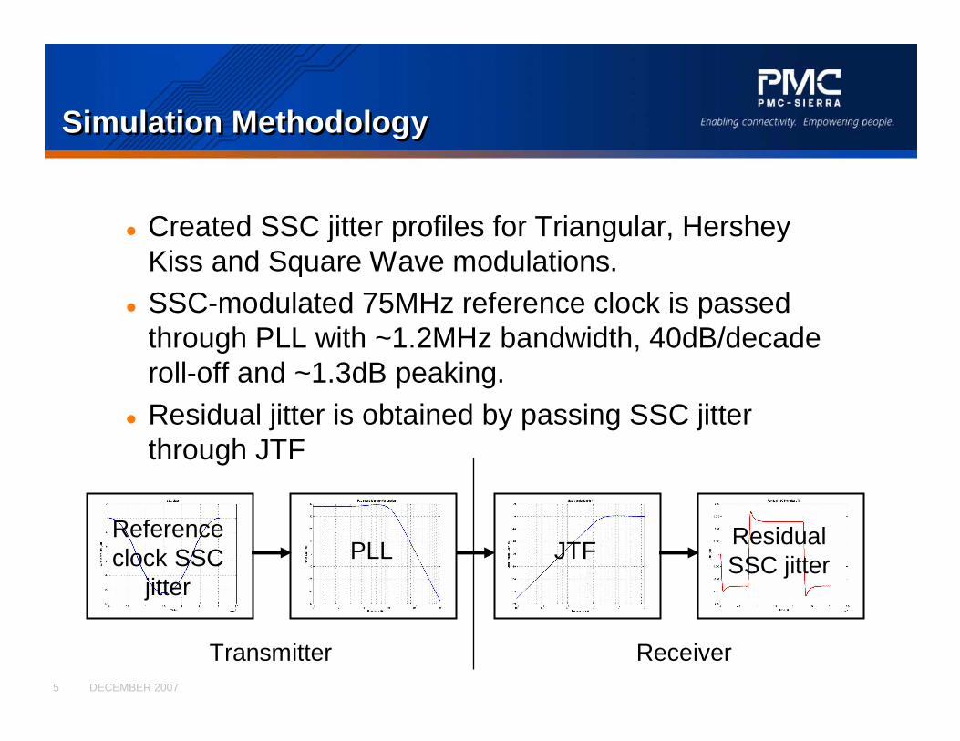
� Created SSC jitter profiles for Triangular, Hershey Kiss and Square Wave modulations.
� SSC-modulated 75MHz reference clock is passed through PLL with ~1.2MHz bandwidth, 40dB/decade roll-off and ~1.3dB peaking.
� Residual jitter is obtained by passing SSC jitter through JTF
PLLResidual SSC jitter
Reference clock SSC
jitter
JTF
Transmitter Receiver

DECEMBER 20076
Triangular SSCFrequency Modulation and JitterTriangular SSCFrequency Modulation and Jitter
� Results for worst-case JTF with triangular modulation

DECEMBER 20077
Hershey Kiss SSCFrequency Modulation and JitterHershey Kiss SSCFrequency Modulation and Jitter
� Results for worst-case JTF with HK modulation

DECEMBER 20078
Square Wave SSCFrequency Modulation and JitterSquare Wave SSCFrequency Modulation and Jitter
� Results for worst-case JTF with square modulation

DECEMBER 20079
Limitation of the JTF as CDR modelLimitation of the JTF as CDR model
� According to the 6G PHY spec (07-339r7), the JTF must be calibrated using D24.3 pattern (110011…). This corresponds to a transition density of 0.5.
� When testing with CJTPAT, the transition density drops to 0.3 inthe long low frequency sequences (repeated D30.3)
� In most CDR architectures, gain is proportional to the transition density
- A CDR that matches the JTF response with D24.3 will have its gain reduced by 40% when receiving D30.3
- SSC residual jitter will increase by ~70% for CJTPAT
DECEMBER 200710
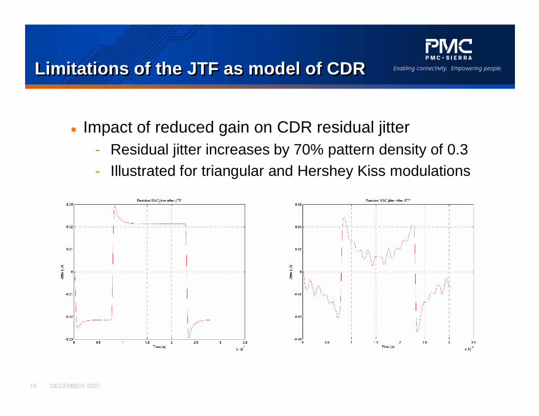
Limitations of the JTF as model of CDRLimitations of the JTF as model of CDR
� Impact of reduced gain on CDR residual jitter- Residual jitter increases by 70% pattern density of 0.3- Illustrated for triangular and Hershey Kiss modulations
DECEMBER 200711
Residual SSC Jitter SummaryResidual SSC Jitter Summary
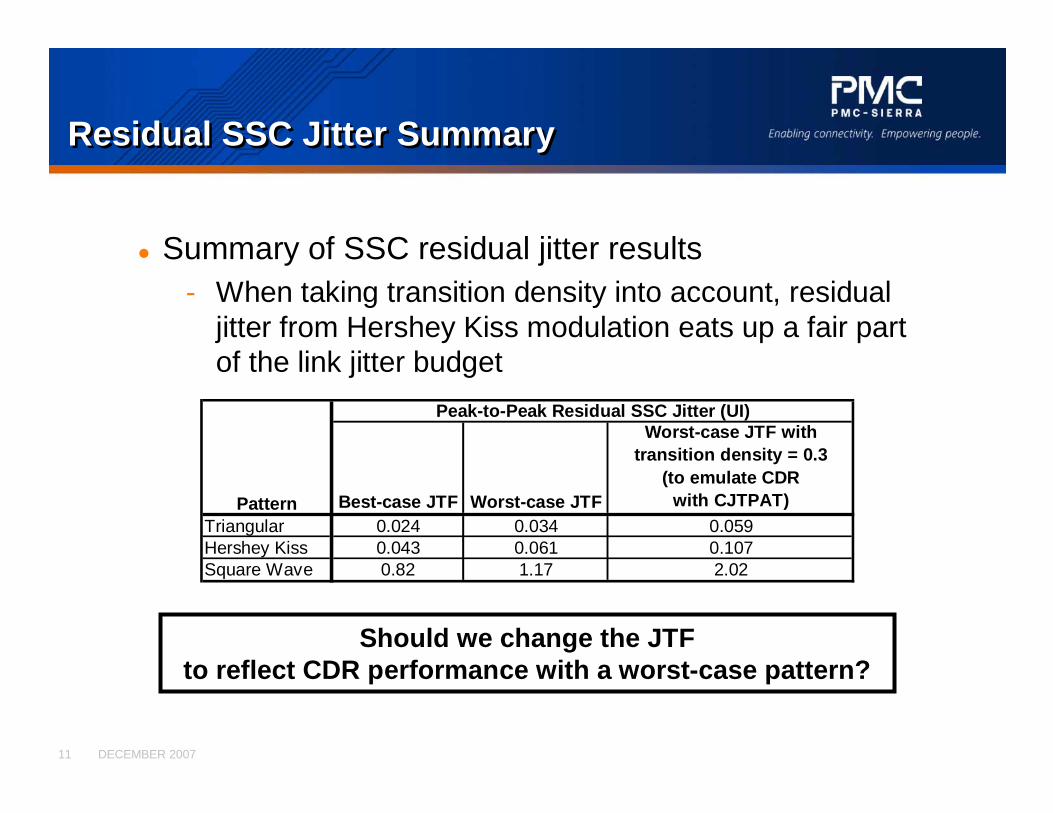
� Summary of SSC residual jitter results- When taking transition density into account, residual
jitter from Hershey Kiss modulation eats up a fair part of the link jitter budget
Should we change the JTF to reflect CDR performance with a worst-case pattern?
Best-case JTF Worst-case JTF
Worst-case JTF with transition density = 0.3
(to emulate CDR with CJTPAT)
Triangular 0.024 0.034 0.059Hershey Kiss 0.043 0.061 0.107Square Wave 0.82 1.17 2.02
Peak-to-Peak Residual SSC Jitter (UI)
Pattern
DECEMBER 200712
Value of Residual Jitter From SSC Slope (1)Value of Residual Jitter From SSC Slope (1)
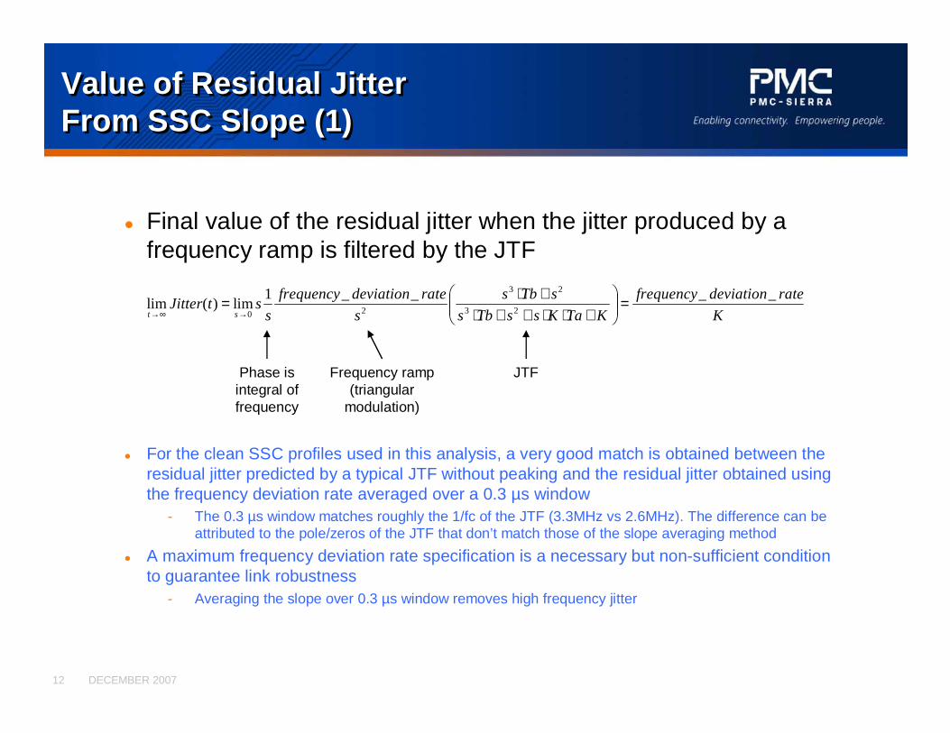
� Final value of the residual jitter when the jitter produced by afrequency ramp is filtered by the JTF
K
ratedeviationfrequency
KTaKssTbs
sTbs
s
ratedeviationfrequency
sstJitter
st
____1lim)(lim 23
23
20=��
�
����
�
+⋅⋅++⋅+⋅=
→∞→
JTFFrequency ramp (triangular
modulation)
Phase is integral of frequency
� For the clean SSC profiles used in this analysis, a very good match is obtained between the residual jitter predicted by a typical JTF without peaking and the residual jitter obtained using the frequency deviation rate averaged over a 0.3 µs window
- The 0.3 µs window matches roughly the 1/fc of the JTF (3.3MHz vs 2.6MHz). The difference can be attributed to the pole/zeros of the JTF that don’t match those of the slope averaging method
� A maximum frequency deviation rate specification is a necessary but non-sufficient condition to guarantee link robustness
- Averaging the slope over 0.3 µs window removes high frequency jitter

DECEMBER 200713
Value of Residual Jitter From SSC Slope (2)Value of Residual Jitter From SSC Slope (2)
� Comparing residual jitter for Triangular and Hershey Kiss SSC profiles- Response from typical JTF with fc=2.6MHz and -73.5dB gain at 30kHz (red)
- Response from frequency deviation rate (slope) averaged over 0.307µs (green)
Residual Jitter from Triangular SSC Profile Residual Jitter from Hershey Kiss SSC Profile
DECEMBER 200714
Value of Residual Jitter From SSC Slope (3)Value of Residual Jitter From SSC Slope (3)
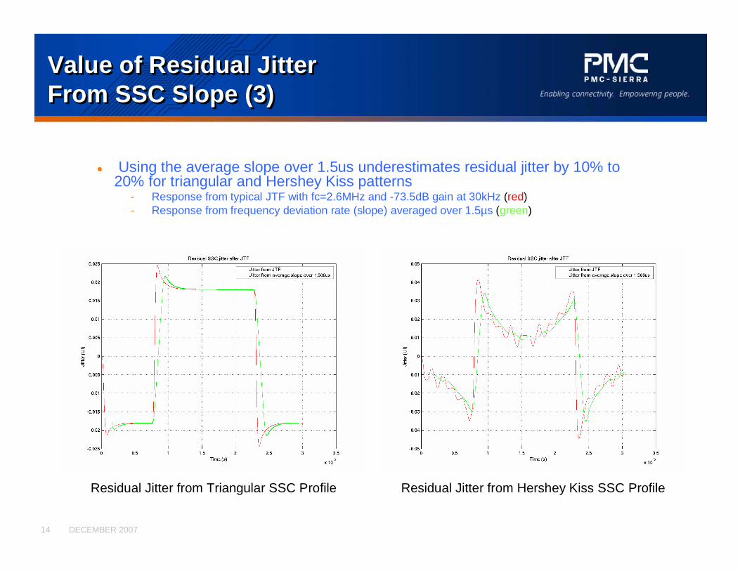
� Using the average slope over 1.5us underestimates residual jitter by 10% to 20% for triangular and Hershey Kiss patterns
- Response from typical JTF with fc=2.6MHz and -73.5dB gain at 30kHz (red)- Response from frequency deviation rate (slope) averaged over 1.5µs (green)
Residual Jitter from Triangular SSC Profile Residual Jitter from Hershey Kiss SSC Profile
DECEMBER 200715
Tentative Link Budget For Discussion (1)Tentative Link Budget For Discussion (1)
� Definition of Terms- Data Dependent Jitter (DDJ): Inter-Symbol Interference- Non-Compensable Jitter (NCJ): jitter that cannot be
corrected by the receiver- Data Dependent Non Compensable Jitter: in this link budget,
this is specifically the ISI that cannot be corrected by the SAS-2 reference receiver.
- Since the SAS-2 reference receiver is a 3-taps DFE, this corresponds to ISI from the pre-cursor taps as well as all post-cursors taps after and including the 4th.
- It is split from the rest of the non-compensable jitter since it can be controlled by changing tx pre-emphasis.
DECEMBER 200716
Tentative Link Budget For Discussion (2)Tentative Link Budget For Discussion (2)
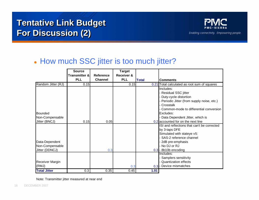
� How much SSC jitter is too much jitter?Source
Transmitter & PLL
Reference Channel
Target Receiver &
PLL Total CommentsRandom Jitter (RJ) 0.15 0.15 0.21 Total calculated as root sum of squares
Bounded Non-Compensable Jitter (BNCJ) 0.15 0.05 0.2
Includes:- Residual SSC jitter- Duty-cycle distortion- Periodic Jitter (from supply noise, etc.)- Crosstalk- Common-mode to differential conversionExcludes: - Data Dependent Jitter, which is accounted for on the next line
Data-Dependent Non-CompensableJitter (DDNCJ) 0.3 0.3
ISI and reflections that can't be corrected by 3-taps DFESimulated with stateye v5:- SAS-2 reference channel- 2dB pre-emphasis- No DJ or RJ- 8b10b encoding
Receiver Margin (RMJ) 0.3 0.3
Includes:- Samplers sensitivity- Quantization effects- Device mismatches
Total Jitter 0.3 0.35 0.45 1.01
Note: Transmitter jitter measured at near end

DECEMBER 200717
Tentative link budget considerationsTentative link budget considerations
� Is 0.05 UI (8 ps) a good number for channel non-compensable jitter (BNCJ)?
- Crosstalk- Common-mode to differential conversion- Reflections
� Is 0.30 UI (50 ps) a sufficient margin for the receiver?- Should we tighten other specs for more receiver
margin?� Can we gain margin by increasing pre-emphasis?
Tx Pre-Emphasis (dB) DDNCJ for 3 taps DFE (UI)0 0.32 0.33 0.296 0.299 0.22

DECEMBER 200718
Tentative SSC SpecificationsTentative SSC Specifications
� CDR considerations- SSC modulation shall not exceed the +/-2300 ppm range- The slope of the frequency deviation should not exceed 1200 ppm/µs
when averaged over any 0.3 µs (±0.01 µs) window of the SSC modulation profile
- This limit is based on allocating the full transmitter BNCJ budget (0.15UI) to the SSC residual jitter, for a nominal JTF (fc=2.6MHz, gain(30kHz)=-73.5dB) that has its gain scaled by 60% to emulate the effect of a pattern density of 0.3 on a typical CDR. A transmitter with a 1200 ppm/µs SSC slope should not contribute any other form of jitter.
- SSC modulation shall not cause the transmit jitter to exceed the jitter spec when filtered through the JTF
- Activation or deactivation of SSC on a link that is not DC idle shall be done without violation of the transmit jitter specifications after filtering through the JTF.
� Average frequency deviation due to asymmetry in the SSC profile shall be within 288 ppm- Based on max ALIGNs insertions/deletions in previous versions of SAS (1/2048) minus
the max frequency offset between the local and far end crystals (200ppm)� Average frequency deviation over any 16.67us period is not an issue
- FIFO depth larger than 14 D-Words (~5600ppm)


