Description 02001.00 Scope - This Section includes the requirements for portland cement concrete (concrete) for structural, precast prestressed, or paving applications. 02001.01 General - Produce concrete according to these Specifications and referenced Sections of ASTM C 94, Standard Specification for Ready-Mixed Concrete. Provide quality control according to Section 00165. 02001.02 Abbreviations and Definitions: ASTV - Actual Strength Test Value - average of test cylinder compressive strengths cm - Cementitious Materials ƒ'c - Minimum Specified Compressive Strength at 28 days ƒ'cr - Average Compressive Strength Over-design. The average strength required to assure
that, with normal variations, the concrete will meet ƒ'c GGBFS - Ground Granulated Blast Furnace Slag HPC - High Performance Concrete HRWRA - High-Range Water-Reducing Admixture (super-plasticizer) PPCM - Precast prestressed concrete member w - Water WRA - Water Reducing Admixture Cementitious Materials - Included but not limited to portland cement, fly ash, silica fume, ground granulated blast furnace slag, and metakaolin. High Performance Concrete - Concrete designed for enhanced durability and performance characteristics. High performance concrete is identified on the Plans by the letters "HPC" in front of the concrete class designation (for example, HPC4000 - 3/4). Moderate Exposure - Elevations below 1,000 feet. Modifiers - Pozzolans, latex. Pozzolans - Fly ash. Severe Exposure - Elevations 1,000 feet and above. 02001.10 Materials - Furnish materials meeting the requirements of the following:
Admixtures ..........................................................................................02040 Aggregates..........................................................................................02690 Cement ...............................................................................................02010 Modifiers .............................................................................................02030 Water ..................................................................................................02020
02001.20
704
02001.20 Concrete Properties, Tolerances, and Limits - Provide concrete that is a workable mixture, uniform in composition and consistency, and having the following properties;
(a) Strength - Provide concrete meeting the required Classes shown in the Contract Documents. The class of concrete designates the minimum required compressive strength, ƒ'c at 28 days, and the nominal maximum size of aggregate to be used in the concrete (for example, Class 3300 - 3/4: ƒ'c is 3,300 psi with a nominal maximum size aggregate of 3/4 inch).
Table 02001-1
Concrete Strength and Water/Cementitious Material (w/cm) Ratio
Type of Concrete
Strength (psi)
Maximum w/cm Ratio
3300 0.50 3300 (Seal) 0.45
4000 0.48 4000
(Deck) 0.40
HPC4000 0.40 5000 and
above 0.40 1
Structural
HPC5000 and above 0.40
Paving 4000 0.44 1 PPCM's with cast-in-place decks and no
entrained air may have w/cm as follows: 5000 psi - 0.48; 5500 psi - 0.44; 6000 psi and up - 0.42
(b) Air Entrainment - Provide all concrete, except PPCM with cast-in-place decks, seal concrete, and drilled shaft concrete with entrained air in the amounts shown in Table 02001-2. Field measured entrained air content shall be within ± 1.5% of target air entrainment values.
(c) Slump - Provide concrete at the appropriate slump shown in Table 02001-3. Take corrective action to maintain a consistent slump at the point of discharge from the delivery vehicle.
Table 02001-3
Concrete Slump Condition Slump
Concrete without WRA 4" max. Concrete with WRA 5" max. Concrete with HRWRA 5 1/2" ± 2 1/2"
(d) Temperature - Provide concrete, at time of placement, at a temperature between a minimum of 50 °F and a maximum of 90 °F, except the maximum bridge deck concrete temperature shall be 80 °F.
Concrete Mix Designs 02001.30 Concrete Mix Design - Submit new or current mix designs, prepared by a CCT, for each required class of structural or paving concrete to the Engineer for review. Allow 14 calendar days for the review. Design mixes by the volumetric method in ACI 211.1 to achieve the properties of 02001.20. Do not proceed with concrete placement until the Engineer has determined that the mix design complies with the Specifications. Review of concrete mix designs does not relieve the Contractor of the responsibility to provide concrete meeting the Specification requirements. High performance concrete (HPC) mix designs shall either contain cementitious material with 66% portland cement, 30% Fly ash, and 4% Silica fume; or have trial batches performed to demonstrate that the alternate mix design provides a maximum of 1,000 coulombs at 90 days when tested according to AASTHO T 277. 02001.31 Concrete Constituents:
(a) Portland Cement - Use AASHTO M 85 or ASTM C 150, Type I or II cement for structural or paving concrete. Use AASHTO M 85 or ASTM C 150, Type III cement for precast prestressed concrete. (b) Pozzolans - Except for HPC, pozzolans or GGBFS may be used separately or in combinations up to 30% of the total cementitious materials content. (c) Modifiers - Modifiers may be used separately or in combinations as approved by the Engineer. (d) Blended Hydraulic Cement - Blended hydraulic cement may be used subject to the limits of 02001.31(b) and 02010.20. (e) Chemical Admixtures - Use chemical admixtures according to the manufacturer's recommendations. Use WRA in all seal concrete and in Class 5000 concrete or greater. Use HRWRA in all HPC.
02001.31(e)
706
Use a superset extender from the QPL in all concrete for bridge decks. Use an appropriate amount to extend the initial set time of the concrete by 90 minutes. (f) Aggregate - If the nominal maximum size of the coarse aggregate is not included as a part of the class of concrete shown on the plans, any size from 1 1/2 inch to 3/4 inch nominal maximum size aggregate may be used except:
• Use 3/4 inch nominal maximum size or larger aggregates in bridge deck concrete. • Use 1 1/2 inch nominal maximum size aggregates in paving concrete. • Use 3/8 inch nominal maximum size aggregates in drilled shafts unless otherwise indicated.
Proportion all HPC for a minimum coarse aggregate absolute solid volume according to Table 02001-4:
1 1/2" 0.46 Two or more aggregate products or sources meeting specifications may be blended to improve concrete properties. Blending non-specification aggregate materials, except for gradation, with specification materials is not allowed.
02001.32 New Mix Designs - Prepare new mix designs for submittal according to the following:
(a) Trial Batch - Make at least one trial batch for each concrete mix design. Prepare and test trial batches using the same materials and having the same plastic properties of concrete that will be used in the Project. Simulate haul time and mixing conditions to ensure proper workability at the jobsite. (b) Plastic Concrete - For each trial batch, test the temperature, slump, density, and air content and compute the w/cm ratio and yield according to the following test methods:
Test Test Method
Sampling Fresh Concrete WAQTC TM 2 Slump AASHTO T 119 Density AASHTO T 121 Yield AASHTO T 121 Air Content AASHTO T 152 Concrete Temperature AASHTO T 309 Molding Concrete Specimens AASHTO T 23 or R 39 1 Water-Cement Ratio 2
1 Cast cylinders in single-use plastic molds 2 Use ODOT's Field Operating Procedure for AASHTO T 121 in the MFTP
02001.35(c)
707
(c) Strength Tests - For each trial batch, cast at least three test cylinders in 6 inch x 12 inch or 4 inch x 8 inch single-use plastic molds. Cast and cure all cylinders according to AASHTO T 23 or AASHTO R 39, and test at 28 days according to AASHTO T 22. Cast three flexural beams for paving concrete trial batches according to AASHTO T 23 or AASHTO R 39. Test flexural beams at 28 days according to AASHTO T 97.
02001.33 Required Over Design Strength (ƒ'cr) for New Mix Designs - Provide test data and calculations demonstrating compliance of the trial batch cylinder's ASTV with the requirements of either (a) or (b) below.
(a) ƒ'cr = ƒ'c x 1.20 Up to Class 6000 ƒ'cr = ƒ'c x 1.15 Class 6000 and higher (b) ƒ'cr = ƒ'c + 1.34 x S Up to Class 6000 ƒ'cr = ƒ'c + 1.28 x S Class 6000 and higher Where: S is the standard deviation of 28 day cylinder strengths from a similar class (± 1,000 psi)
mix design produced at the same plant. There shall be at least 15 sets of 28 day cylinders from this similar class mix design to use option (b).
(c) Flexural Beams - Flexural beams for paving concrete mix designs shall achieve 600 psi at 28 days.
02001.34 Current Mix Designs - Mix designs that meet the requirements for the specified class of concrete and are currently being used or have been used within the past 12 months on any project, public or private may be submitted for review. 02001.35 Required Submittals for Mix Designs - Submit the following information for each concrete mix design:
• Weight per cubic yard (pounds per cubic yard) of cementitious material, modifiers, fine and coarse aggregates (SSD), and mix water.
• Absolute volumes of cementitious material, modifiers, fine aggregates and coarse aggregates (SSD), and mix water.
• Dosage rates for chemical admixtures. (c) Aggregates - Identify the aggregate source by the ODOT source number. Report current values of the following:
• Bulk specific gravities (SSD) • Fine aggregate absorptions • Coarse aggregate absorptions • Dry-rodded density of coarse aggregates • Fineness modulus of sand used in the mix design calculations
02001.35(d)
708
(d) Cementitious Material - For each cementitious material used, identify the following:
• Manufacturer • Brand name • Type • Relevant Specification • Source or location plant
(e) Modifiers - For each modifier used, identify the following:
• Manufacturer • Brand name • Source • Relevant specification • Class
(f) Admixtures - For each admixture used, identify the following:
• Manufacturer • Brand name • Design dosage rate
(g) Water - Identify the source of water to be used. (h) Plastic Concrete Tests - Report the temperature, slump, density, air content, yield, and w/cm ratio of the trial batch or the average of these values for the cylinder sets presented for evaluation of a current mix design. (i) Compressive Strength Test Results - Report the individual test results and the ASTV of cylinders from the trial batch or the average for the cylinder sets presented for evaluation of a current mix design. (j) Strength Analysis - Provide an analysis, showing all calculations, demonstrating that the mix design meets the requirements of 02001.33. (k) Quality Control Personnel - Provide the name and certification number of the CCT who prepared the mix design, the QCT who performed the plastic concrete tests and cast the test cylinders, the laboratory where the cylinders were tested, and the CSTT who tested the cylinders.
02001.36 Adjusting Concrete Proportions - After a mix design has been reviewed and accepted, submit any proposed adjustments to concrete proportions for review. Significant changes to the mix design (such as decreases in cementitious material content, increases in pozzolans that replaces cement, or the use of aggregates from a different source) may require verification of compressive strength performance by trial batch, according to 02001.32, or test results from field tests according to 02001.33. Aggregates from new sources shall meet aggregate source quality requirements according to Section 02690. 02001.37 Trial Batch Costs - Furnish all materials, equipment and work required for designing the mixes, testing materials, and making trial batches to verify the design for final use at no additional cost to the Agency.
02001.50(c)
709
02001.40 Concrete Production - Produce concrete according to the following sections of ASTM C 94, Standard Specification for Ready-Mixed Concrete: ASTM Section ASTM Title 9. Measuring Materials 10. Batching Plant 11. Mixers and Agitators 12. Mixing and Delivery 02001.50 Quality Control Personnel - Provide the following certified technicians:
(a) Certified Aggregate Technician (CAgT):
• Duties:
• Sample and test aggregates. • Sample and test each stockpiled size according to the test procedures and at the frequencies
shown in the Field Tested Materials Guide section of the MFTP. • Record and evaluate test results according to Section 00165. • Provide Stat-Spec results to the Engineer.
(b) Quality Control Technician (QCT):
• Duties:
• Attend pre-placement meetings for bridge deck pours and paving. • Be at the concrete placement site when concrete placement is in progress. • Have a copy of the mix design on-site and available during concrete placement. • Obtain and check each batch ticket upon arrival of the concrete at the jobsite for the correct
mix design. • Sample the concrete and test for ambient air temperature, plastic concrete temperature,
slump, air content, density, w/cm ratio and yield at the frequencies required by and according to the tests listed in the MFTP, after concrete mixture proportions are adjusted in the field, and at such times as requested by the Engineer.
• Notify the Contractor and the Engineer immediately when the concrete is not in compliance with the Specifications.
• Be in direct contact with the CCT by telephone, radio or other means to convey information. • Notify the CCT of loads rejected and the reason for rejection. • Notify the CCT immediately whenever the density of the plastic concrete varies from the mix
design target by more than ± 3 pounds per cubic foot. • Notify the CCT immediately whenever the w/cm ratio varies from the mix design target by
more than ± 0.03. (c) Concrete Control Technician (CCT):
• Duties
• Prepare new concrete mix designs. • Adjust current mix designs.
02001.50(c)
710
• Control production of the concrete. • Test the fine and coarse aggregates for total moisture content according to AASHTO T 255
before batching is started and when there is a significant change in the slump of the concrete. Moisture testing may be by an alternate method if approved by the Engineer. Provide moisture content test results to the Engineer upon request.
• Visually inspect the coarse aggregate for changes in moisture content throughout the day. Perform necessary testing for total moisture, and make mixture adjustments if necessary.
• Monitor concrete properties and compressive strength tests throughout the duration of the Project.
• Make adjustments to maintain a satisfactory over-design ƒ’cr. • Perform an analysis and make necessary adjustments whenever the unit weight of the
plastic concrete varies from the mix design by more than ± 3 pounds per cubic foot. Submit a written analysis along with any recommendations to the Engineer by the middle of the following work shift.
• Submit to the Engineer, in writing, adjustments made to the mix design. • Perform an analysis and verify the accuracy of coarse and fine aggregate moistures
whenever the water-cementitious material ratio varies from the mix design target by more than ± 0.03 and submit to the Engineer by noon of the following workday.
(d) Concrete Strength Testing Technician (CSTT):
• Duties:
• Receive concrete test cylinders • Record data • Strip cylinders • Store cylinders • Test Cylinders • Record test data • Report test data
02001.60 Delivery Tickets - Send a concrete delivery ticket with each load of concrete supplied to the Project. Each delivery ticket shall include the following information:
• Concrete supplier’s name, address and telephone number • Address and telephone number of batch plant if different from above • Date and time the concrete batch was produced • ODOT mix design number • Size of load batched • Weights or volumes of constituents batched in the load • Amount of water that can be added at the job site
Record the amount of water added at the job site on the delivery ticket.
02010.20
711
Section 02010 - Portland Cement
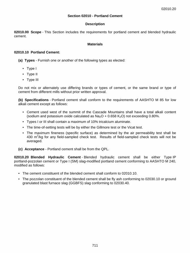
Description 02010.00 Scope - This Section includes the requirements for portland cement and blended hydraulic cement.
Materials 02010.10 Portland Cement:
(a) Types - Furnish one or another of the following types as elected:
• Type I • Type II • Type III
Do not mix or alternately use differing brands or types of cement, or the same brand or type of cement from different mills without prior written approval. (b) Specifications - Portland cement shall conform to the requirements of AASHTO M 85 for low alkali cement except as follows:
• Cement used west of the summit of the Cascade Mountains shall have a total alkali content (sodium and potassium oxide calculated as Na2O + 0.658 K2O) not exceeding 0.80%.
• Types I or III shall contain a maximum of 10% tricalcium aluminate. • The time-of-setting tests will be by either the Gillmore test or the Vicat test. • The maximum fineness (specific surface) as determined by the air permeability test shall be
430 m2/kg for any field-sampled check test. Results of field-sampled check tests will not be averaged.
(c) Acceptance - Portland cement shall be from the QPL.
02010.20 Blended Hydraulic Cement - Blended hydraulic cement shall be either Type IP portland-pozzolan cement or Type I (SM) slag-modified portland cement conforming to AASHTO M 240, modified as follows:
• The cement constituent of the blended cement shall conform to 02010.10. • The pozzolan constituent of the blended cement shall be fly ash conforming to 02030.10 or ground
granulated blast furnace slag (GGBFS) slag conforming to 02030.40.
02020.00
712
Section 02020 - Water
Description 02020.00 Scope - This Section includes the requirements for water used in mixing concrete, mortar, grout, and other applications when specified or directed.
Materials 02020.10 Water:
(a) General - Water used in mixing or curing concrete, for mortar and grout, and in mixing cement-treated base shall be reasonably clean, and free of oil, sugar, organic matter or other substances injurious to the finished product. (b) Potable - Potable water may be used without testing if the Contractor provides a quality compliance certificate verifying that the water has met the limits of this Section according to tests made within the last two years. Water approved for public use by the Oregon Health Division may be accepted for use without testing. (c) Nonpotable or Unknown Quality - Water of non-potable, unknown or suspected quality shall be tested at no additional cost to the Agency according to AASHTO T 26 before use in the Project and shall meet the following limits:
If any of the test data are outside these limits, the water may be accepted on the basis of an evaluation of the reduction in seven-day compressive strength, which shall not exceed 10.0%. In marine environments, the chloride ion percentage shall be limited to a maximum of 0.10%. (d) Recycled Mix Water - Water from mixer washout operations may be used in mixing concrete provided it is:
• Within the limits of ASTM C 94, Table 1, Acceptance Criteria for Questionable Water Supplies, and ASTM C 94, Table 2, Chemical Limitations for Wash Water. In addition the specific gravity maximum limit is 1.03.
• Tested at a weekly interval for at least four weeks prior to use on the Project. The testing frequency may be reduced to monthly thereafter providing no single test exceeds the limits set above. Required tests include the physical tests in Table 1 of ASTM C 94, the chemical tests in Table 2 of ASTM C 94, and testing for specific gravity. The testing shall be at no additional cost to the Agency. The test results shall be provided to the Engineer prior to use on the Project.
02020.10(d)
713
• Made up from a dilution process rather than a concentration process. (A dilution process in one in which the reclaimed water is extensively diluted and continuously agitated to keep solids in a state of suspension).
• Free of coloring agents.
• Not used when the ambient temperature is 85 °F or above.
• Not used when the ambient temperature is 40 °F or lower. • Not used as more than 75% of the water added to the batch. • Not used in structure decks.
02030.00
714
Section 02030 - Modifiers
Description 02030.00 Scope - This Section includes the requirements for fly ash, silica fume, latex, and ground granulated blast furnace slag used in portland cement concrete.
Materials 02030.10 Fly Ash:
(a) Types - Fly ash shall be Class C, Class F, or Class N from the QPL, and shall conform to AASHTO M 295, including Table 2, except that:
• Loss on Ignition (LOI) shall be 1.5% maximum. • Moisture content shall be 1% maximum. • Amount retained on the No. 325 sieve shall be 30% maximum.
(b) Acceptance - Fly ash will be accepted for immediate use if accompanied by a test results certificate according to 00165.35. As a check on material conformance, fly ash may be sampled at the site of work for verification testing.
02030.20 Silica Fume:
(a) Types - Provide the silica fume admixture as a slurry containing silica fume, water, and a high range water reducer, or as a densified powder. The silica fume portion shall conform to AASHTO M 307, including Table 1a, Optional Chemical Requirements. (b) Acceptance - Silica fume will be accepted for immediate use if accompanied by a test results certificate according to 00165.35. If the silica fume admixture is supplied as a slurry, the certificate shall indicate the silica fume content of the slurry as a percent by weight. If the silica fume is supplied as a densified powder, do not allow the packaging to enter the concrete mixture.
02030.30 Formulated Latex Admixture - Formulated latex admixture shall be from the QPL and be a nontoxic, film-forming, polymeric emulsion in water to which all stabilizers have been added at the point of manufacture. It shall be homogeneous and uniform in composition, and meet the following requirements: Polymer Type Stabilizers Styrene Butadiene Latex Nonionic Surfactants Portland Cement Composition Polydimethyl Siloxane Solids, % by weight, min. 46.0 Volume Density, lb/gal, min. 8.4 at 77 °F pH 9.0 to 11.0 Color White Latex admixtures that have not been stored according to the manufacturer's recommendations will not be accepted. 02030.40 Ground Granulated Blast Furnace Slag (GGBFS) - GGBFS shall meet the requirements of AASHTO M 302.
02040.10
715
Section 02040 - Chemical Admixtures
Description 02040.00 Scope - This Section includes the requirements for air-entraining, water-reducing, retarding, and accelerating admixtures.
Materials 02040.10 Materials - Furnish admixtures from the QPL, except as follows: An admixture that does not appear on the QPL may be used if, prior to use, the Contractor provides a test results certificate demonstrating the admixture has been tested and conforms to these Specifications. The Agency may sample and test admixtures according to 00165.35. Chloride content of any admixture used in portland cement concrete in contact with embedded metals shall not exceed 0.5% by weight of the admixture when tested according to ODOT TM 505. Admixtures shall conform to the following requirements: Admixture Specification Air-entraining AASHTO M 154 (ASTM C 260) Water-reducing AASHTO M 194 (ASTM C 494) Retarding AASHTO M 194 (ASTM C 494) Accelerating AASHTO M 194 (ASTM C 494)
02050.00
716
Section 02050 - Curing Materials
Description 02050.00 Scope - This Section includes the requirements for liquid compounds, evaporation reducers, polyethylene films, and curing blankets used to cover concrete and other surfaces to retain moisture and to cure.
Materials 02050.10 Liquid Compounds - Furnish liquid membrane-forming curing compounds from the QPL and meeting the requirements of AASHTO M 148, except that testing will be done according to ODOT TM 721. The specified drying time requirement will be waived. The test application rate shall be 1 gallon per 200 square feet. All compounds shall be class A. Solvent-based compounds shall be Type 1-D. 02050.20 Polyethylene Films - Furnish clear or white polyethylene films for curing concrete meeting the requirements of AASHTO M 171. 02050.30 Curing Blankets - Furnish curing blankets from the QPL. 02050.40 Liquid Evaporation Reducer Compounds - Furnish evaporation reducer compounds from the QPL.
02060.10
717
Section 02060 - Sealers
Description 02060.00 Scope - This Section includes the requirements for epoxy cement sealers.
Materials 02060.10 Epoxy Cement - Furnish epoxy cement from the QPL.
02070.00
718
Section 02070 - Bonding Agents
Description 02070.00 Scope - This Section includes the requirements for epoxy and non-epoxy bonding agents.
Materials 02070.10 Epoxy Bonding Agents - Furnish epoxy bonding agents from the QPL. 02070.20 Non-Epoxy Bonding Agents - Furnish non-epoxy bonding agents from the QPL.
02080.50
719
Section 02080 - Grout
Description 02080.00 Scope - This Section includes the requirements for epoxy, non-epoxy, keyway, and portland cement grout.
Materials 02080.10 Epoxy Grout - Furnish epoxy grout from the QPL. 02080.20 Non-Epoxy Grout - Furnish non-epoxy grout from the QPL. 02080.30 Keyway Grout - Furnish grout used in the keyways of precast prestressed concrete members that is non-shrink, nonferrous, non-epoxy grout with a minimum design strength of 5,000 psi in 28 calendar days. Furnish keyway grout from the QPL and use according to the manufacturer's recommendations. 02080.40 Portland Cement Grout - Furnish portland cement grout consisting of one part portland cement and three parts sand by weight, thoroughly mixed with a minimum amount of water to produce a thick, creamy consistency. Sand shall meet the requirements of 02690.30 and cement shall meet the requirements of Section 02010. 02080.50 Tendon Grout - Furnish tendon grout from the QPL that meets vertical rise requirements.
02090.00
720
Section 02090 - Lime
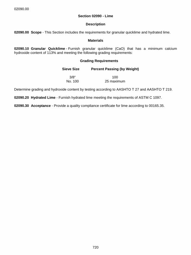
Description 02090.00 Scope - This Section includes the requirements for granular quicklime and hydrated lime.
Materials 02090.10 Granular Quicklime - Furnish granular quicklime (CaO) that has a minimum calcium hydroxide content of 113% and meeting the following grading requirements: Grading Requirements Sieve Size Percent Passing (by Weight) 3/8" 100 No. 100 25 maximum Determine grading and hydroxide content by testing according to AASHTO T 27 and AASHTO T 219. 02090.20 Hydrated Lime - Furnish hydrated lime meeting the requirements of ASTM C 1097. 02090.30 Acceptance - Provide a quality compliance certificate for lime according to 00165.35.
02110.10(f)
721
Wood Products
Section 02110 - Posts, Blocks, and Braces
Description 02110.00 Scope - This Section includes the requirements for wood posts and blocks for guardrail, median barrier, signs, fence posts, and braces for fencing.
Materials 02110.10 Guardrail Posts:
(a) General - Furnish posts for guardrail and median barrier of the size shown, manufactured from Douglas fir, Hem-fir, or Southern Yellow Pine. Wood for posts shall have a minimum extreme fiber bending stress (Fb) of 1,200 psi. Only treated posts from approved suppliers that are listed in the "Nonfield-Tested Materials Acceptance Guide" will be allowed. (b) Grading - Grading of posts shall conform to the following:
• Douglas Fir - Conform to the requirements for No. 1 posts and timbers as specified in either paragraph 80.11 of the current WWPA Grading Rules, or paragraph 131-b of the current WCLIB Grading Rules.
• Hem-fir - Conform to the requirements for select structural posts and timbers as specified in
either paragraph 80.10 of the current WWPA Grading Rules, or paragraph 131-a of the current WCLIB Grading Rules.
• Southern Yellow Pine - Conform to the requirements for No. 1 timbers as specified in section 402 of the current Southern Pine Inspection Bureau (SPIB) Grading Rules.
(c) Certificates - Furnish certificates of lumber inspection by a recognized inspection agency. (d) Fabrication - Before preservative treatment, bore all holes and make all necessary cuts as shown. (e) Preservative Treatment - Treat posts according to Section 02190. (f) Seasoning and Checking - Each preservative treated post shall show evidence of reasonable amount of seasoning and/or conditioning having occurred prior to treatment, so that further shrinkage of treated posts will not create checking which would expose untreated wood. At the time of inspection at the plant and at the time of installation each treated post will be subject to inspection for evidence of seasoning having occurred. The presence of checking on the surface of the post will not be cause for rejection unless the width of the widest check, shake, or split exceeds 1/2 inch (surface measurement). If an otherwise acceptable treated post has a through check, shake, or end split in the same slope of grain or plane as the bolt hole and extending from the top of the post to within 3 inches of the bolt hole, the post will be rejected unless it is provided with a tight fastening across the separation, centered on the post, and 2 inches below the top. Fasten with a 1/2 inch diameter galvanized bolt and nut with a galvanized washer under the bolt head and under the nut after final curing of post is achieved. Treat holes for fastenings according to 00570.40.
02110.10(g)
722
(g) Inspection, Rejection and Marking at Plant - Posts shall be subject to inspection at the treating plant at any time before, during or after treatment. Normally, inspection of treated posts will be made by the Agency's inspector not later than 10 calendar days after treatment, provided the inspector is notified of the time that treating is to be done. Inspection of treated posts for compliance with the requirements of 02110.10(e) will be according to applicable AWPA standards, except as follows:
• The inspector will choose the number of treated posts from any one charge of the treating cylinder for determining penetration of treatment.
• Each post selected for testing shall be representative as a basis of acceptance or rejection of a pro rata number of posts in the charge.
• If 20% of the posts randomly selected for testing fail to conform to requirements, all of the posts in the entire charge from which they are selected may be classed as unacceptable.
At the inspector’s discretion, each treated post or a representative random selection of treated posts may be inspected for compliance with the requirements of 02110.10(f) "Seasoning and Checking". Posts which fail to conform to requirements of this subsection will be subject to rejection at the treating plant singly, by partial lots, or by whole lots. (A "lot" comprises the posts in any charge of the treating cylinder.) Each treated post shall bear a permanent mark or metal tag which identifies the supplier and year of treatment, placed by the supplier either:
• On the top of the post, or • On the back of the post, 8 inches to 10 inches below the bolt hole.
(h) Field Inspection, Acceptance and Rejection - At the time of installation inspect each post for:
• Width of widest check, shake, or split. • Damage to treated wood affecting soundness. • Visible exposure of untreated wood. • Conformance to the requirements of 02110.10(b) through 02110.10(f). • Preservative visibly leaching from the post.
Posts that show a check, shake, or split exceeding 1/2 inch in width (surface measurement) on any surface will be rejected. Posts that show surface damage may be repaired by field treating with preservatives according to AWPA Standard M 4. Repair posts that have splits or checks, or where shakes have opened or deepened sufficiently to expose untreated wood, by treating with a field preservative from the QPL applied to all opened or deepened wood separations and completely filling the separations to the surface of the post. Remove treated wood posts that have been rejected for any one or more of the above deficiencies or faults and not repaired as stated above. Acceptance of material will be according to 00165.35, 02110.10(g), and these Specifications.
02110.40(a)
723
02110.20 Guardrail Blocks:
(a) General - Furnish wood guardrail blocks of the dimensions shown. Blocks shall be either Douglas fir or Hem-fir meeting the requirements of 02110.10, or pine or Southern Yellow Pine meeting the requirements of 02110.20(b) and 02110.10 except for 02110.10(b). The requirements of marking and branding the treated blocks, according to the last paragraph of 02110.10(g), will be waived provided that the supplier of the treated blocks furnishes certification with each shipment stating that the blocks conform to Specifications and that the preservative treating was done under the inspection and with the approval of the Engineer. (b) Grading - Pine guardrail blocks shall conform to the requirements of paragraph 80.11 of the current WWPA Grading Rules. Southern Yellow Pine guardrail blocks shall conform to the requirements for No. 1 timber as specified in section 402 of the current SPIB Grading Rules. (c) Recycled Plastic - Recycled plastic guardrail blocks from the QPL may be used. (d) Acceptance - Acceptance of material will be according to 00165.35 and this Section.
02110.30 Fence Posts and Braces - Fence posts and brace rails shall be of the sizes and dimensions shown and shall be of sound Douglas fir, western hemlock, or western pine free from decay, end splits, and multiple crooks. Seasoning checks of not more than 5/16 inch width (surface measurement) will be allowed. Allowable crooks may be in one plane only. A line drawn between the centers of the butt and tip of each post and brace rail shall not fall outside of the actual longitudinal centerline of the post or rail by more than 1.67% of its length, with an allowable maximum of 2 inches. Posts and brace rails may be square, rough, or dressed lumber, or may be peeled round posts, as the Contractor elects. Round members shall be free from bark, protruding knots and irregularities detrimental to a pleasing appearance. Fabricate posts and brace rails before pressure treatment. Where field boring or field cutting of a treated member is required, field-treat the exposed untreated surface of the member according to 00570.40. The size of holes after treatment shall not exceed the size of the dowels or bolts to be inserted by more than 1/16 inch. Posts intended to be driven may be machine-pointed on either the small end or the large end, before pressure treatment. Pressure treat the posts and brace rails according to Section 02190. Acceptance of material will be according to 00165.35 and these Specifications. 02110.40 Wood Sign Posts - Fabricate wood sign posts from either Douglas fir, surfaced four sides (S4S) and free of heart center (FOHC) or Hem-fir (S4S) (FOHC).
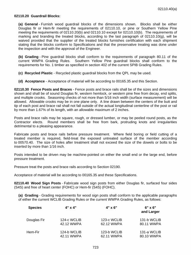
(a) Grading - Grading requirements for wood sign posts shall conform to the applicable paragraphs of either the current WCLIB Grading Rules or the current WWPA Grading Rules, as follows:
Species 4" x 4" 4" x 6" 6" x 6" and Larger
Douglas Fir 124-c WCLIB 123-c WCLIB 131-b WCLIB 42.12 WWPA 62.12 WWPA 80.11 WWPA
Hem-Fir 124-b WCLIB 123-b WCLIB 131-a WCLIB
42.11 WWPA 62.11 WWPA 80.10 WWPA
02110.40(b)
724
(b) Posts - Construct wood sign posts according to the applicable portions of Section 00570, modified or supplemented as follows:
(1) Length - The length of the posts shall be shown or, where not shown, each post shall be of sufficient length to provide proper sign mounting, a proper mounting height and the required foundation depth. (2) Framing and Boring - Cut, frame and bore timber before pressure treating, to the extent practical. (3) Preservative Treatment - Pressure-treat wood sign posts after fabrication according to Section 02190. (4) Cuts and Abrasions - Treat cuts, abrasions and bolt-holes, prior to shipping, with the same preservative as originally used to treat the post, except that if the post was originally treated with pentachlorophenol - volatile petroleum solvent (LPG) solution, cuts, abrasions and bolt-holes shall be treated with pentachlorophenol - mineral spirits solvent solution according to AWPA Standard M4. (5) Field Repair - Field treat damaged or drilled pressure-treated posts according to 00570.40.
(c) Acceptance - Acceptance of material will be according to 00165.35 and this Section.
02120.40
725
Section 02120 - Poles and Piling
Description 02120.00 Scope - This Section includes the requirements for wood poles for use in illumination and signal installations, and timber piling for structures.
Materials 02120.10 Wood Poles - Furnish all wood poles meeting the current edition of ANSI O5.1, Specifications and Dimensions (for Wood Poles), for Class 4 machine shaved Douglas fir, and treated meeting the requirements of Section 02190. All poles shall be round, sound, well proportioned from butt to tip, and without short kinks or crooks. 02120.20 Timber Piling - Furnish timber piling meeting the requirements of ASTM D 25. The butt or tip size, or whether the piling are to be friction or bearing piles, will be identified in the Special Provisions. All foundation piles shall be Douglas fir. Treat timber piling according to Section 02190. 02120.30 Timber Pile Straps - Straps shall be approximately 1 1/4 inch wide and 0.03 inch thick, manufactured from cold-rolled, heat-treated steel having a minimum ultimate tensile strength of 150,000 psi. The strap shall encircle the pile once and be fastened with a clip that is crimped so that the joint will have a minimum tensile strength of 80% of the tensile strength of the strap. Install the strap after pressure treating of the pile. 02120.40 Acceptance - Acceptance of poles and piling will be according to 00165.35 and this Section.
02130.00
726
Section 02130 - Timber and Lumber
Description 02130.00 Scope - This Section includes the requirements for timber and lumber.
Materials 02130.10 Timber and Lumber - Unless otherwise shown or specified, all lumber and timber shall be S4S Douglas fir. Grading requirements shall be according to the Special Provisions. All lumber shall be grade-stamped or have a mill certification by an American Lumber Standards certified inspection agency. 02130.20 Acceptance - Acceptance of material will be according to 00165.35 and this Section.
02140.20
727
Section 02140 - Glued Laminated Timber Members
Description 02140.00 Scope - This Section includes the requirements for glued laminated timber members.
Materials 02140.10 General - Furnish all structural glued laminated lumber as shown and specified. Manufacture of structural glued laminated work shall conform to the manufacturing requirements of the current ANSI/AITC A190.1 American National Standard, Structural Glued Laminated Timber. Provide quality control according to the AITC 200 "Inspection Manual for Glued Laminated Timber". Lumber shall be Douglas fir, southern pine, western larch, or other species, as shown or specified. Lumber used shall be of a stress grade to provide glued laminated members with the minimum stress values in bending and tension shown or specified. Adhesives shall meet the requirements of the glued laminated lumber standards, and be waterproof. Unless otherwise specified, appearance of members shall be architectural grade as defined in AITC 110 Standard Appearance Grades for Structural Glued Laminated Timber. Seal surfaces of members with penetrating sealer and apply a coat of end sealer to the ends of all members as soon as practical after end trimming, according to AITC Standard for Preservative Treatment of Structural Glued Laminated Timber. Use a clear sealer compatible with the preservative treatment used according to Section 02210. Bundle wrap members according to AITC Recommended Practice for Protection of Structural Glued Laminated Timber During Transit, Storage and Erection. Furnish shop details from the fabricator and obtain approval before commencing the work. Details shall conform to the current AITC Typical Construction Details. 02140.20 Acceptance - Glued laminated timber members will be accepted according to 00165.35 and this Section.
02150.00
728
Section 02150 - Lumber and Timber Connectors
Description 02150.00 Scope - This Section includes the requirements for connectors, bolts, nuts, nails, and miscellaneous hardware for joining lumber and timber.
Materials 02150.10 Lumber and Timber Connectors:
(a) General - Galvanize connectors for treated structures, except those of malleable iron or lightweight connectors, according to AASHTO M 111 (ASTM A 123). (b) Split Ring Connectors - Provide 2 5/8 inch and 4 inch inside diameter split rings manufactured from steel conforming to ASTM A 830 (AISI C1010, SAE 1010). Each ring shall form a closed true circle with the principal axis of the cross section of the ring metal parallel to the geometric axis of the ring. Bevel the metal section from the central portion toward the edges to a thickness less than the mid-section. Cut through the ring in one place in its circumference to form a tongue and slot. Cut connector grooves in timber concentric with the bolt hole and conforming to the cross-sectional shape of the rings, to provide a snug fit. The inside diameter of the groove shall be larger than nominal ring diameter so that the ring can expand slightly during installation. (c) Shear Pate Connectors:
(1) Pressed Steel Type - Provide 2 5/8 inch diameter pressed steel shear plates manufactured from steel conforming to ASTM A 830 (AISI C1010, SAE 1010). Each plate shall be a true circle with a flange around the edge, extending from one face of the plate only and at right angles to the face. The plate portion shall have a central bolt hole and two small perforations on opposite sides of the hole and midway between the center and circumference. (2) Malleable Iron Type - Provide 4 inch diameter malleable iron shear plates manufactured according to ASTM A 47, Grade No. 32510, for malleable iron castings. Each casting shall consist of a perforated round plate with a flange around the edge projecting from one face of the plate only and at right angles to the face. The plate portion shall have a central bolt hole reamed to size with an integral hub concentric with the bolt hole and extending from the same face as the flange.
(d) Bolts, Nuts, Nails, and Miscellaneous Hardware - Provide machine bolts, drift bolts and dowels according to ASTM A 307 or ASTM A 36. Washers may be cast ogee or malleable castings, or they may be cut from steel plate. Galvanize rough hardware, drive pins, expansion bolts, clamps, washers, anchors, joist hangers, bolts and nuts, lag screws, wood screws, spikes and nails according to AASHTO M 232 (ASTM A 153). Provide these items in standard type and make, or as shown. (e) Lightweight Metal Connectors - Lightweight metal connectors are mass produced plate or sheet steel connectors with a maximum thickness of 0.25 inches used to connect wood members to wood, concrete or masonry. Provide lightweight metal fasteners as shown with the required minimum capacities as stated in the special provisions. Provide copies of the test reports from the International Code Council (ICC-ES) showing that the supplied fastener meets the minimum capacities listed in the Special Provisions. All lightweight metal connectors shall be galvanized according to ASTM A 653 (coating designation G185), ASTM A 123, or stainless steel.
02150.20 Acceptance - Lumber and timber connectors will be accepted according to 00165.35 and this Section.
02190.30
729
Section 02190 - Preservative Treatment of Timber
Description 02190.00 Scope - This Section includes the requirements for preservative treatment of lumber, timber, timber piling, guard rail posts and blocks, sign posts, fence posts, and other items as specified.
Materials 02190.10 General - All preservative treatment shall be according to AASHTO M 133 and its referenced AWPA Standards, except that only the following preservatives are allowed:
• Creosote • Pentachlorophenol (any solvent) • Ammoniacal Copper Zinc Arsenate (ACZA) • Chromated Copper Arsenate (CCA), Type A, B, or C • Copper Naphthenate • Ammoniacal Copper Quat, Type B, C, or D
02190.20 Drying Time - When using ACZA, air-dry items as defined in AWPA P5, a minimum of 30 calendar days before installation. Kiln drying for two calendar days may be substituted for 30 calendar days of air-drying. During the period September 1 through May 31, the air-drying shall be under cover at the treatment facility. During the 30 calendar day drying period and until the treated items are installed on the Project, separate each layer of treated items using spacers that are at least 1/2 inch thick. The maximum moisture content shall be 19% prior to installation. Collect all spacers and other treated wood waste from the construction site and dispose of them according to 00290.20. 02190.30 Field Treatment - Field-treat damaged or drilled wood surfaces with a preservative listed in the QPL.
02210.00
730
Coatings
Section 02210 - Coating Materials for Timber and Concrete
Description 02210.00 Scope - This Section includes the requirements for coating materials used on timber and concrete.
Materials 02210.10 General:
(a) Manufacturing - Furnish coating material meeting the following requirements:
• Be prepared at the factory ready for application or mixing of multi-component coatings. Multi-component coating materials shall be proportioned by the manufacturer with each component in its correct proportion and furnished in separate containers ready for field mixing.
• Be homogeneous, free of contamination, and of a consistency suitable for the specified use. • Include additives for control of sagging, pigment settling, leveling, drying, dryer absorption,
skinning, or other properties that affect application and curing. • Not require a pretreatment chemical or material prior to application of the prime coat except as
specifically stipulated in these specifications. • Include required tinting and coloring materials at the time of manufacture. When successive
coats are specified, each coat shall be tinted to provide contrast between coats. The tinting material shall be compatible with the coating material and not detrimental to performance.
• Not vary in composition without prior notice by the manufacturer and approval of the Engineer. No reformulation will be allowed.
All coats in the coating system shall be from the same manufacturer. Apply coating materials before expiration of the manufacturer's recommended shelf life. (b) Packaging - Package the material in containers meeting the following requirements:
• Be new steel or plastic of not more than 6 gallon capacity. • Have a lug type crimp lid with a ring seal, and shall be equipped with ears and bails. • Meet U.S. Department of Transportation's Hazardous Material Shipping Regulations. • Be lined, if necessary, to prevent attack by the coating material. The lining shall not come off
the container. • Be original and unopened. • Be labeled with a quality compliance certificate according to 00165.35 showing the following:
• Manufacturer's name • Exact title of coating material • Agency Specification number, if any • Manufacturer's batch number • Date of manufacture • Shelf life or expiration date • Identification of all toxic substances • Handling and application precautions
02210.30
731
02210.20 Coating Materials for Timber - Furnish coatings for timber from the QPL under the category "Timber Coatings". 02210.21 Sealer for Timber - Furnish clear sealers for timber from the QPL under the category "Timber Sealers". 02210.30 Coating Materials for Concrete - Furnish coatings for concrete from the QPL under the category "Latex Emulsion Paint".
02320.00
732
Geosynthetics and Slope Protection
Section 02320 - Geosynthetics
Description 02320.00 Scope - This Section includes the requirements for geosynthetics used in various applications. 02320.01 Definitions - Geosynthetic terms are defined in 00350.01.
Materials 02320.10 Acceptance:
(a) General Requirements - Furnish all geosynthetics meeting the following requirements:
• Free of defects, cuts or tears. • Resistant to ambient temperatures, acid and alkaline conditions, micro-organisms and insects. • For the intended purpose and have dimensional stability. (1) Geotextiles - Furnish woven or nonwoven geotextiles meeting the following requirements:
• Be composed of long chain, synthetic polymeric filaments or yarns formed into a stable network that retains its relative structure during handling, placement and design service life. At least 95%, by weight, of the long chain polymers shall be a polyolefin or polyester.
• Meet or exceed the properties specified in 02320.20, Table 02320-1. • Be free of any chemical treatment or coating which might significantly reduce permeability. • Have the selvage finished so the outer fibers are prevented from pulling away from the fabric.
(2) Geogrids - Furnish geogrids meeting the following requirements:
• A regular network of integrally connected, polymer, tensile elements with aperture geometry sufficient to permit significant mechanical interlock with the surrounding soil or rock.
• Dimensionally stable and able to retain their geometry under manufacture, transport and installation.
(b) Acceptance Requirements - The actual minimum average roll values furnished by the manufacturer shall be based on representative test results from the manufacturing plant which produced the geosynthetic, and shall meet or exceed each of the specified minimum values. All geosynthetics shall be clearly labeled as being part of the same production run certified as meeting all applicable requirements. (c) Manufacturer’s Documentation - Furnish a Level A or Level B certification, as indicated in the Special Provisions for the applicable geosynthetics.
(1) Level A - Manufacturer’s Test Result Certificate - Furnish a test result certificate according to 00165.35 from the geosynthetic manufacturer. The certificate shall:
• Include the minimum average roll values for each of the specified properties from the same production run as the delivered material.
02320.20
733
• Include test results for factory seams. • Include production run number, production plant name and location.
If the geosynthetic material is modified, remanufactured, relabeled or sewn, furnish an additional certificate from the supplier making the changes that explain the altered properties, seam strength or relabeling. (2) Level B - Manufacturer’s Quality Compliance Certificate - As a basis of acceptance, furnish either a manufacturer’s brochure or a quality compliance certificate, according to 00165.35, with geosynthetic properties shown.
If the brochure or certificate lists typical or average roll values instead of minimum average roll values, then increase by 25% the specified minimum values in Table 02320-1 for grab tensile strength, burst strength and puncture strength to determine compliance.
(d) Manufacturer’s Sampling/Testing - The manufacturer’s reported property values shall be based on the following sampling and testing requirements:
(1) Sampling - Sample all geosynthetics according to ASTM D 4354. The production unit used for sampling shall be a roll or sheet. (2) Testing - Perform the specified tests to determine geotextile properties for the intended application(s). The tensile strength requirements shall be tested in both machine and cross-machine directions.
(e) Agency Check Tests - The Agency reserves the right to sample and test products for compliance with pertinent requirements, according to 00165.02. When the Agency performs check tests, the entire production run will be accepted or rejected according to 00150.25, if any of the average roll values of tested rolls are less than the specified minimum values.
02320.11 Seam Testing and Acceptance:
(a) Factory Seams - Where factory seams are made, the sheets of geotextile shall:
• Be sewn together using a lock type stitch Type 301 or 401 as shown. • Be sewn with polymeric thread that is at least 95%, by weight, polyolefin or polyester, and as
resistant to deterioration as the geotextile being sewn. • Have test results showing that the seams meet or exceed 90% of the specified tensile strength
minimum values for the intended application. • Nylon thread will not be allowed.
(b) Field Seams - Where field sewn seams will be used, furnish:
• The manufacturer’s test result certificate, according to 00165.35, that includes wide strip, tensile strength test results and verifies that seam tensile strength and seam grab tensile strength meet or exceed 90% of the minimum specified tensile strength values for the geotextile.
• A field-stitched seam test sample. 02320.20 Geotextile Property Values:
Melting point (minimum) ASTM D 276 °F ⎯ ⎯ ⎯ ⎯ ⎯ ⎯ 300
1 Slit film or slit tape fabrics are not acceptable. 2 As measured according to ASTM D 4632.
734
02320.20 .
02340.30
735
Section 02340 - Rock Gabion Baskets
Description 02340.00 Scope - This Section includes the requirements for rock gabion baskets of twisted or welded wire mesh.
Materials 02340.10 General - Provide wire mesh material free of breaks in the wire, breaks at weld points or other deficiencies. Individual wires of either style mesh shall meet the following minimum requirements:
Galvanizing ............................................... 0.80 oz. per sq. ft. minimum Tensile strength 1 ....................................................60,000 psi minimum Wire diameter tolerance limit ................................................... ± 0.004"
1 Tensile area includes galvanizing Welded wire shall also conform to AASHTO M 55 (ASTM A 185) except that the weld shears shall be 600 pounds for 11 gauge, and 800 pounds for 9 gauge wires. All wire sizes are after galvanizing. Tie wires and internal connecting wires shall be galvanized and no smaller than 13 1/2 gauge. Spiral binders may be used as an alternate to tie wire for basket assembly and basket-to-basket connections. Spiral binders shall be 9 gauge, galvanized, and have a 3 inch pitch. High tensile fasteners of the locking spring steel clip or clamp-on ring type may be used as alternates to tie wire for basket assembly only. High tensile fasteners shall be fabricated from 11 gauge steel wire with a minimum tensile strength of 240,000 psi. Provide a Class 3 zinc coating according to ASTM A 764. High tensile fasteners shall provide a closed position tensile strength of 600 pounds. All wire shall be galvanized according to ASTM A 641. 02340.12 Twisted Wire Mesh Gabion Baskets - Furnish gabion panels of the twisted mesh style manufactured from 11 gauge with 9 gauge selvage wires. The mesh shall form a uniform hexagonal pattern and shall be formed with a non-raveling twist. The major axis (maximum line dimensions) of any hexagonal opening shall not exceed 4.75 inches. The area of the hexagonal opening, approximately 3.2 inches by 4.5 inches, shall not exceed 9.5 square inches. 02340.20 Welded Wire Mesh Gabion Baskets - Furnish gabion panels of the welded mesh style manufactured from 11 gauge or 9 gauge wire. The mesh shall form a nominal 3 inch by 3 inch grid pattern and conform to AASHTO M 55 (ASTM A 185). The maximum line dimension of any opening shall not exceed 4.75 inches. The 12 inch and 18 inch high mattresses shall be made from 11 gauge panels. Gabions of square cross section (cubical-celled units) may be made with either 9 gauge or 11 gauge panels, except that within the same unit, panels of dissimilar wire sizes may not be mixed. Galvanized 9 gauge stiffeners, placed diagonally in the baskets at the vertical one-third points, as shown on the plans or as recommended by the manufacturer, may be used instead of perpendicular cross ties. 02340.30 PVC Coated Wire Mesh Gabion Baskets - The wire type used for PVC coated wire mesh gabions shall be either twisted wire mesh or welded wire mesh and shall conform to 02340.00 and 02340.12 or 02340.20.
02340.30
736
The PVC coating for twisted wire mesh gabions shall be extruded onto the wire core before weaving the coated wire into a double twisted hexagonal mesh. The use and minimum diameter of the various wires is as follows:
• Gabion Panel wire core shall be manufactured from galvanized 12 gauge wire core. The overall minimum diameter of the galvanized wire core plus PVC coating shall be 0.136 inch.
• Selvage and reinforcing wire shall be of heavily galvanized 10 gauge wire core coated with PVC and having an overall minimum diameter (galvanized wire core plus PVC coating) of 0.165 inch.
• Lacing and connecting wire shall be of heavily galvanized 13 1/2 gauge wire core coated with PVC and having an overall minimum diameter (galvanized wire core plus PVC coating) of 0.120 inch.
02340.40 Fabrication - Fabricate gabions so that the sides, ends, lid and diaphragms can be assembled at the construction site into rectangular baskets of the specified sizes. Dimensions for heights, lengths and widths of gabion baskets shall be as indicated on the plans with a tolerance of plus or minus 3%. Gabions shall be of single unit construction. Either connect the base, lid, ends and sides into a single unit or connect one edge of these members to the base section of the gabion in such a manner that strength and flexibility at the point of connection is at least equal to that of the mesh. If the length of the gabion exceeds its horizontal width, equally divide the gabion by diaphragms into cells whose length does not exceed the horizontal width. The diaphragm material shall be of the same mesh and size as the body of the gabions. Furnish the gabion with the necessary diaphragms secured in proper position on the base in such manner that no additional tying at this juncture will be necessary. Assemble the wire mesh panels (base, ends, sides, diaphragms and lid) so strength and flexibility at connections is at least equal to that of a single panel. 02340.50 Acceptance - Provide a quality compliance certificate for gabion baskets according to 00165.35.
02350.20
737
Section 02350 - Metal Bin Retaining Walls
Description 02350.00 Scope - This Section includes the requirements for galvanized steel sheets and hardware for the assembly of metal bin retaining walls.
Materials 02350.10 Base Metal, Galvanizing, and Thickness - Design all members, fittings and appurtenances as integral units or parts of the whole assembly. The galvanized sheets used in fabricating the members shall conform to the requirements of AASHTO M 218. Bolts, nuts and miscellaneous hardware shall be galvanized or otherwise protected with approved coatings and shall be of sizes and shapes suitable for use with the members furnished. Fabricate the members from the specified base metal of the thickness shown. In the absence of given thickness or dimensions for any member, fitting or appurtenance, the thickness of metal or dimensions of the member shall be as required to fully develop the strength of the members whose thickness and dimensions are given, and which are used in structural combination. 02350.20 Fabrication - Fabricate all members so members of the same nominal size are fully interchangeable. Fabricate and punch the members so no drilling, punching or drifting to correct defects in manufacture will be required during field assembly. Any members having improperly punched holes will be rejected. Replace with a member with properly punched holes.
02410.00
738
Drainage and Water Distribution Materials
Section 02410 - Concrete and Plastic Pipe
Description 02410.00 Scope - This Section includes the requirements for nonreinforced and reinforced concrete pipe, concrete drain pipe and tile, polyethylene pipe, and polyvinyl chloride (PVC) pipe.
Materials 02410.10 Concrete Pipe - Furnish concrete pipe meeting the following requirements:
(a) End Designs - Where rubber gasket joints are used, modify the design of the ends of the pipe sections according to AASHTO M 198 to accommodate rubber gaskets. (b) Sloped or Skewed Ends - If the ends of pipe require sloped ends, skewed ends or both, fabricate the ends in a manner that provides good workmanship and a smooth finish, and protection to otherwise exposed reinforcement where applicable. (c) Markings - Indent the markings required by AASHTO M 86 (ASTM C 14) in the outside surface of each section of pipe. (d) Concrete Pipe Field Permeability Tests - The Engineer may require field permeability tests on a maximum of 5% of each lot, class, or size of pipe according to ASTM C 497 on pipe 24 inches in diameter and smaller. Provide all the necessary labor, equipment, water and materials at the site for performing field permeability tests. At the option of the pipe supplier, and with the approval of the Engineer, individual field permeability tests may be performed at the point of manufacture. (e) Concrete Pipe Plant Air Test - The Engineer may require that each length of concrete pipe 12 inches in diameter and smaller be given an individual air test at the point of manufacture. Use test equipment approved by the Engineer and a test pressure of at least of 10 psi. Each length shall show no appreciable loss of air after five seconds. When individual air testing is performed, no field or shop permeability tests will be required. (f) Nonreinforced Concrete Pipe - Provide nonreinforced or plain circular concrete pipe and special sections conforming to the requirements of AASHTO M 86 (ASTM C 14) or ASTM C 985 and this Section. (g) Reinforced Concrete Pipe - Provide reinforced concrete pipe and special sections conforming to the requirements of AASHTO M 170 (ASTM C 76) and this Section, except as follows.
(1) Special Sections - Furnish special sections such as elbows, wyes, tees, crosses, bends and reducers as shown, specified or directed. In the absence of any design or specifications, the special sections shall be of the design recommended by the manufacturer for the intended use. Generally the special sections shall conform to the requirements specified for the pipe with which it is to be used. Fabricate special sections with components from tested and approved lots. Maintain production dates of components.
02410.80
739
(2) Load Strength - Reinforced concrete pipe having the same D-load strengths as those specified to be furnished under AASHTO M 170 (ASTM C 76) may be furnished according to AASHTO M 242 (ASTM C 655). (3) Acceptance - The basis of acceptance for reinforced concrete pipe manufactured according to AASHTO M 170 (ASTM C 76), and AASHTO M 242 (ASTM C 655) will be Paragraph 5.1.1 of AASHTO M 170.
(h) Concrete Drain Pipe - Use circular, nonreinforced perforated concrete pipe and special sections for subsurface drainage conforming to the requirements of AASHTO M 175 (ASTM C 444), Type 1, all applicable requirements of AASHTO M 86 (ASTM C 14), except indent the markings required by AASHTO M 86 (ASTM C 14) in the outside surface of each section of pipe. (i) Concrete Drain Tile - Provide concrete drain tile conforming to the requirements of AASHTO M 178 (ASTM C 412).
02410.60 Polyethylene Pipe - Furnish polyethylene pipe meeting the following requirements:
Corrugated polyethylene drain pipe ....................................... AASHTO M 252 Corrugated polyethylene culvert pipe................ AASHTO M 294, Type S or D Corrugated polyethylene storm sewer pipe....... AASHTO M 294, Type S or D
The allowable nominal inside diameter of polyethylene pipe is as follows:
Watertight joints for corrugated polyethylene pipe shall meet the requirements of ASTM D 3212 and shall be listed in the QPL. 02410.65 Solid Wall High Density Polyethylene (HDPE) Pipe - Furnish pipe resin that has a hydrostatic design basis of 1,600 psi when tested and analyzed according to ASTM D 2837, and has a material designation code of 3408 as listed by the Plastic Pipe Institute. The resin shall meet the requirements of ASTM D 3350 and have a minimum cell classification of PE345444C (Code D or E may also be used for pipe bursting and lining pipe and for slip lining pipe). The polyethylene composition for code C classification shall contain a minimum of 2% and not more than 3% by weight of well-dispersed and finely divided carbon black when tested according to ASTM D 1603 and ASTM D 4218. The pipe shall contain no recycled compound except that generated in the manufacturer's own plant from resin of the same specification from the same raw material pipe. Pipe (excluding black colored pipe) stored outside shall not be recycled. Provide pipe and fittings meeting the requirements of ASTM F 714 and ASTM D 3261 as modified for the specified material. 02410.70 Polyvinyl Chloride (PVC) Pipe - Furnish PVC subsurface drain pipe and fittings meeting the requirements of ASTM D 2729. Furnish PVC sanitary, storm, culvert, siphon, and irrigation pipe and fittings with 2 feet or more cover that have a minimum pipe stiffness of 46 psi or a minimum SDR of 35 and meet the requirements of sewer pipe ASTM D 3034, ASTM F 679, or ASTM F 794. Furnish PVC sanitary, storm, culvert, siphon, and irrigation pipe and fittings with less than 2 feet but at least 1 foot cover meeting the requirements of AWWA C 900 or AWWA C 905. 02410.80 Acceptance - Except as provided in 02410.10(g-3), acceptance of nonreinforced concrete pipe, reinforced concrete pipe, concrete drain pipe, concrete drain tile, polyethylene pipe, polyvinyl chloride pipe, and hardware will be according to 00165.35 and this Section.
02420.00
740
Section 02420 - Metal Pipe
Description 02420.00 Scope - This Section includes the requirements for corrugated steel pipe, helical rib pipe, arch type pipe, aluminum pipe, ductile iron pipe, and special sections intended for use for storm drainage, underdrains and culverts, and not intended for the conveyance of sanitary or industrial waste.
Materials 02420.10 Corrugated Steel Pipe and Pipe Arches - Furnish corrugated steel pipe, helical rib pipe, pipe arches and special sections meeting the requirements of AASHTO M 36 (ASTM A 760) Types I, IA, and II, except as follows:
(a) Shapes - Provide either full-circle or elliptical pipe, as the Contractor may elect, unless otherwise shown or specified. The shapes of pipe fabricated and furnished may include any of the following:
• Full-Circle Pipe - Fabricate helical rib pipe in full-circle cross section only. • Arch-Type Pipe • Elliptical Pipe - Full-circle pipe distorted 5% out-of-round by shop fabrication to form an
elliptical cross section with the major axis vertical. • Half-Circle Pipe - Fabricate as half sections of full-circle pipe of the same diameter. • Nestable Pipe - Fabricate in two separate half sections designed to fit and fasten together to
form a full-circle cross section of specified diameter. Fasten the two half sections together by approved means which shall provide at least 90% of the strength of a standard riveted longitudinal seam.
(b) Connecting Bands - Use connecting bands conforming to the details shown on the plans to make field joints for pipes and pipe arches not requiring watertight joints. (c) Special Sections - Furnish special sections such as elbows, wyes, tees, crosses, bends, reducers and flared inlets as shown or as directed. Generally, special sections shall conform to the requirements specified for the pipe with which they are used, and shall be connected to the pipe or to each other with connecting bands specified for use with the pipe to which they are connected. For elbows of 30° or greater total angle, use three-piece sections of approximately equal length and equal-angle segments or pieces. Weld joints according to recognized standard practice and repair any damaged zinc or aluminum coating according to 02420.10(d). (d) Repair of Damaged Coating - In addition to the methods given in AASHTO M 36 (ASTM A 760) the Contractor may repair damaged zinc or aluminum coating by removing all loose or cracked coating, removing all welding flux, wire brushing the damaged area, and applying two coats (minimum 2 mils total thickness) of a high zinc dust content paint conforming to the general requirements of ASTM A 780.
02420.20(a)
741
Damaged zinc or aluminum coating within 3/8 inch of the ends of pipe sections caused by production cut-off of pipe need not be repaired. Coating damage on edges of connecting bands need not be repaired. (e) Irrigation Pipe - In irrigation pipe installations, where Type D coating (AASHTO M 190) is not specified, the Contractor will be allowed to furnish pipe with Type D coating.
(1) Riveted Seams - If pipes are not furnished with Type D coating, do the following:
• Place a bead or strip of approved caulking compound, 1/8 inch minimum diameter or thickness, between the laps of all riveted seams.
• Rivet the annular seams of riveted pipe at spacings not greater than 3 inches. Rivet in a single row the longitudinal seams of pipes less than 42 inches in diameter. Place one rivet in each valley and one on each crest of the corrugations.
• Double rivet the longitudinal seams of pipes 42 inches and larger in diameter in each valley of the corrugations and place a single rivet on each crest of the corrugations.
• At the intersection of longitudinal and circumferential seams, close the gap caused by the three-sheet lap by special fabrication. Fabricate a special longitudinal seam at the ends of pipe sections for a sufficient distance to clear the coupling bands.
Spot welding of the seams of corrugated metal pipe used in irrigation pipe installations will not be allowed. (2) Field Joints - Use connecting bands conforming to the details shown, and make the field joints watertight.
(f) Siphon Pipe - Fabricate corrugated steel pipe used in siphons with watertight seams. Field joints shall provide circumferential and longitudinal strength to preserve the pipe alignment, prevent separation of pipe sections and provide a watertight joint. Attach the connecting bands so they lap a nearly equal portion of each pipe section to be connected. (g) Sloped or Skewed Ends - If the ends of pipe culverts require sloped ends, skewed ends or both, fabricate the ends in a manner that provides good workmanship and a smooth finish. Restore zinc or aluminum coating as directed according to 02420.10(d), and bituminous protective coatings and linings when specified.
02420.11 Ductile Iron - Furnish ductile iron pipe conforming to the requirements of AWWA C150. Use Pressure Class 150 - 350 or Special Thickness Class 50 - 56, as directed. 02420.20 Protective Coatings - If specified or shown, furnish corrugated metal pipes with protective coatings as follows:
(a) Bituminous Protective Coatings - Provide corrugated metal pipe and connecting bands with bituminous coatings conforming to the requirements of AASHTO M 190 and the following:
• Before immersion, the metal shall be free of grease, dirt, dust, moisture or other contaminants. • Apply the initial bituminous coating by one of the processes under 02420.20(a-1) or
02420.20(a-2). • If a second dip is required to meet the coating thickness requirements of AASHTO M 190, the
time and temperature requirements of 02420.20(a-1) or 02420.20(a-2) need not be followed for the second dip.
02420.20(a)
742
• The paved invert for both Type B and Type C coatings on either circular or arch type pipe shall fill the corrugations for at least 40% of the circumference of the pipe.
(1) Pipe Not Preheated - The temperature of the asphalt at the time of pipe immersion shall be 400 °F ± 5 °F and the duration of the immersion shall conform to the following schedule:
Metal Thickness (Inch) Minimum Immersion Time Steel Aluminum (Minutes)
0.064 0.060 2.5 0.079 0.075 3.0 0.109 0.105 5.0 0.138 0.135 6.5 0.168 0.164 8.0 (2) Pipe Preheated - At the time of pipe immersion the asphalt shall have a temperature of 380 °F ± 5 °F and the pipe shall be preheated to a temperature 300 °F to 350 °F.
(b) Type D, Fully-Bituminous Coated, Fully-Lined - The interior lining shall be smooth, uniform and free from sags and runs. Slight residual corrugations due to cooling and shrinkage of the lining will not be cause for rejection. At the three-sheet lap an interior nonuniformity equal to the thickness of the sheet will be allowed. Maintain the thickness of the lining to the ends of the pipe. (c) Optional Paved Invert - If an asphalt coated pipe with a paved invert (Type C coating) is shown or specified, a centrifugally-applied interior lining conforming to Type D coating may be furnished as an alternate, providing the minimum thickness of bituminous coating over the crests of the corrugations is not less than 1/4 inch. (d) Polymeric Coatings - If polymeric coating is shown on the pipe data sheet, use a coating from section 02420.20 of the QPL.
02420.30 Corrugated Steel Pipe for Underdrains - Furnish corrugated steel pipe for underdrains conforming to the requirements of AASHTO M 36 (ASTM A 760) Type III - Underdrain Pipes, except as modified in 02420.10(c) and 02420.10(d), and as follows:
(a) Class IV - Semicircular pipe may be used only as an alternate with the 6 inch size of perforated full-circle drain pipe. (b) Connecting Bands - Connecting bands for underdrain pipe field joints shall conform to the designs shown.
02420.40 Corrugated Aluminum Alloy Pipe - Furnish corrugated aluminum alloy pipe, helical rib pipe, pipe arches and special sections conforming to the requirements of AASHTO M 196 (ASTM B 745), Types I, II and III, except as follows:
(a) Shapes - The shapes of the pipes to be furnished may include any of the shapes described in 02420.10(a). (b) Connecting Bands - Use connecting bands conforming to the requirements of AASHTO M 196 (ASTM B 745) and the details shown to make field joints for pipes and pipe arches not requiring watertight joints. (c) Special Sections - Furnish special sections such as elbows, wyes, tees, crosses, bends, reducers and flared inlets as shown or as directed.
02420.60
743
Generally, special sections shall conform to the requirements specified for the pipe with which they are used, and shall be connected to the pipe or to each other with connecting bands specified for use with the pipe to which they are connected. For elbows of 30° or greater total angle, use a three-piece section of approximately equal length and equal-angle segments or pieces. (d) Irrigation Pipe - In irrigation pipe installations where Type D coating is not shown or specified, the Contractor will be allowed to furnish pipe with Type D coating. If pipes are not furnished with Type D coating, all riveted seams shall conform to the applicable provisions of 02420.10(e-1). Use connecting bands conforming to AASHTO M 196 (ASTM B 745) and the details shown, and make the field joints watertight for pipe installations used in irrigation. (e) Siphon Pipe - Fabricate corrugated aluminum alloy pipe used in siphons with watertight seams. Field joints shall provide circumferential and longitudinal strength to preserve the pipe alignment, prevent separation of pipe sections and provide a watertight joint. Fabricate the connecting bands from aluminum alloy conforming to AASHTO M 196 (ASTM B 745). Attach the connecting bands so they lap a nearly equal portion of each pipe section to be connected. (f) Sloped or Skewed Ends - If the ends of pipe culverts require sloped ends, skewed ends or both, fabricate the ends in a manner that provides good workmanship and a smooth finish. Repair bituminous protective coatings and linings when specified.
02420.50 Corrugated Aluminum Alloy Pipe for Underdrains - Furnish corrugated aluminum alloy pipe for underdrains conforming to the requirements of AASHTO M 196 (ASTM B 745) Type III, except as follows:
(a) Special Sections - The provisions of 02420.40(c) apply. (b) Connecting Bands - Connecting bands for field joints shall conform to the requirements of AASHTO M 196 (ASTM B 745) and the details shown.
02420.60 Acceptance - Acceptance of pipes, underdrains, and protective coatings will be according to 00165.35 and this Section.
02430.00
744
Section 02430 - Structural Plate Pipe
Description 02430.00 Scope - This Section includes the requirements for steel and aluminum alloy plates and hardware for structural plate pipe.
Materials 02430.10 Galvanized Steel Plates:
(a) General - Furnish galvanized steel plates for structural plate pipe conforming to the requirements of AASHTO M 167 (ASTM A 761). (b) Plates for Pipe Arches - The top plate(s) shall form an arc between 180 and 155 degrees. The bottom plate(s) shall form an arc between 50 and 10 degrees. Join the top plate(s) at each end to the bottom plate(s) with corner plates to form an arc with a radius between 16 inches and 21 inches or between 29 inches and 34 inches, as applicable, and forming an arc between 87.5 and 75 degrees. (c) Forming and Punching Plates - Form plates to provide lap joints. Punch the bolt holes so that all plates with the same dimensions, curvature, thickness, and number of bolts per foot of seam are interchangeable. Curve each plate to the proper radius so that the cross-sectional dimensions of the finished structure will be as shown or as specified. Unless otherwise specified, fabricate bolt holes as follows:
• Two rows along longitudinal seams. • Center-to-center spacing not more than 10 inches along circumferential seams. • Center of hole to edge of the plate at least 1.75 times the diameter of the bolt. • Longitudinal seam bolt holes shall not exceed the diameter of the bolt by more than 1/8 inch.
The above provisions are for standard punching. Provide additional bolt holes for special conditions of installation when specified or shown. (d) Sloped and Skewed Ends - Cut plates for forming sloped ends, skewed ends or both, to give the angle of slope or skew shown. Burnt edges shall be free from oxide and burrs. Legibly identify each cut plate to designate its proper position in the finished structure.
02430.20 Aluminum Alloy Plates - Furnish aluminum alloy plates for structural plate pipe conforming to the requirements of AASHTO M 219 (ASTM B 746). Fabricate according to 02430.10(b) through 02430.10(d). 02430.90 Bolts, Nuts, and Washers - Furnish bolts, nuts, and washers for use with galvanized steel structural plate pipe conforming to the requirements of AASHTO M 167 (ASTM A 761) and galvanized according to AASHTO M 232 (ASTM A 153). Furnish bolts, nuts, and washers for use with aluminum alloy structural plate pipe conforming to the requirements of AASHTO M 219 (ASTM B 746) and galvanized according to AASHTO M 232 (ASTM A 153). 02430.95 Acceptance - Acceptance of structural plate pipe and hardware will be according to 00165.35 and this Section.
02440.50(a)
745
Section 02440 - Joint Materials
Description 02440.00 Scope - This Section includes the requirements for joint fillers, seals, gaskets and water stop for concrete pipe joints, manhole section joints, bridge joints, and miscellaneous concrete applications.
Materials 02440.10 Preformed Joint Fillers for Concrete - Furnish preformed joint fillers for concrete from the QPL conforming to the requirements of AASHTO M 153 or AASHTO M 213. Fillers conforming to AASHTO M 213, except the binder, if other than bituminous material, may be used provided they otherwise meet this Specification and they have been demonstrated to be rot and vermin proof for a period of at least five years. Unless otherwise specified or indicated, the Contractor may elect to furnish either type specified in this subsection. 02440.11 Poured Joint Sealant - Furnish a two-component, low modulus, rapid-cure joint sealant from the QPL. 02440.14 Backer Rod - Furnish a closed-cell, non-gassing foam material backer rod from the QPL. 02440.15 Lubricant/Adhesive - Furnish a lubricant/adhesive that is recommended by the seal manufacturer. 02440.19 Steel Bridging Plate - Furnish a hot-dip galvanized, conforming to AASHTO M 111 (ASTM A 123), merchant quality steel bridging plate with a minimum thickness of 1/4 inch and a width of 8 inches, cut in lengths of 4 feet or more. Drill spike holes at 12 inch centers along the centerline of the plate before galvanizing. Repair galvanization according to ASTM A 780. 02440.20 Preformed Joint Seals - Furnish compression joint seals conforming to the requirements of AASHTO M 297. Use strip seals conforming to ASTM D 5973. 02440.21 Elastomeric Concrete - Furnish elastomeric concrete from the QPL. 02440.30 Hot Poured Joint Filler - Furnish hot poured joint filler from the QPL and conforming to the requirements of AASHTO M 324, Type II (ASTM D 6690, Type II). 02440.40 Gaskets for Concrete Pipe and Precast Manhole Section Joints:
(a) Preformed Flexible Joint Sealant - Furnish materials for tongue and groove or key lock manhole joints conforming to the requirements of AASHTO M 198 (ASTM C 990). (b) Rubber Gaskets - Furnish materials for O-ring manhole and concrete pipe joints conforming to AASHTO M 315 (ASTM C 443).
02440.50 Joint Materials for Concrete Precast Manhole Section Joints:
(a) Mortar - Furnish mortar conforming to the requirements of ASTM C 387, or proportioned one part Type II portland cement to two parts clean, well-graded sand passing a No. 6 screen. Admixtures may be used not exceeding the following percentages by weight of cement:
Hydrated lime ........................................................................................10% Diatomaceous earth or other inert materials .......................................... 5%
The consistency of the mortar shall be such that it will readily adhere to the precast concrete if using the standard tongue-and-groove type joint.
02440.50(b)
746
(b) Non-Epoxy (Non-Shrink) Grout - Furnish a non-epoxy (non-shrink) grout from the QPL. Place or pack non-shrink grouts only with the use of a non-epoxy bonding agent from the QPL, applied to all cured concrete surfaces being grouted. Use a bonding agent compatible with the grout used.
02440.60 Plastic Compound for Precast Manhole Section Joints - Furnish a plastic compound that is specifically manufactured for the intended use and:
• Has a putty-like, preformed homogeneous blend of hydrocarbon resins and rubber or plasticizing materials with not more than 50% by weight of inert mineral filler.
• Is pliable at temperatures between 32 °F and 135 °F. A specimen at 77 °F and 1/2 inch square in cross section shall stretch at least 1 1/2 inches before rupture when tested with the apparatus described in ASTM D 113.
• Adheres firmly and cohesively to the precast manhole sections when the compound-sealed joint is flexed to its maximum extent.
• Includes a primer solution recommended by the compound manufacturer. • Conforms with Federal Specification SS-S-00210 (GSA-FSS).
02440.70 Water Stop - Furnish either plastic or rubber water stop, as the Contractor elects, manufactured to the dimensions shown and meeting the following requirements:
(a) Plastic - Polyvinyl chloride water stop shall be manufactured from virgin polyvinyl chloride (PVC) compound. No reclaimed PVC will be allowed. The water stop shall have the following properties:
ASTM Test Specification Test Method (Minimum)
Tensile Strength, psi D 412 1,800 Elongation, % D 412 350 100% Modulus, psi D 412 760 Low Brittle Temperature D 746 - 50 °F Cold Bend Test 1 No Failures
1 Samples maintained at -70 °F for two hours, then bent quickly around a 1/4 inch mandrel
to 180 degrees. (b) Rubber - Manufacture rubber water stop to the dimensions shown, in such a manner that the finished product has an integral cross section which will be dense, homogeneous, and free from porosity and other imperfections. The water stop shall have the following properties:
• Hardness - The Shore A Durometer hardness of 60 to 70 when tested according to ASTM D 2240.
• Elongation - Minimum of 450%. • Tensile Strength - Minimum of 3,000 psi. • Water Absorption - Maximum of 5% by weight after immersion in water for two days at 158 °F. • Tensile Strength after Aging - The test specimen, after accelerated aging of seven days
at 158 °F, shall retain not less than 80% of the original tensile strength. The tensile strength of the test specimen, after accelerated aging of 48 hours in oxygen at 158 °F and tensile stress of 300 psi, shall be not less than 80% of the original tensile strength.
02440.80
747
• Compression Set - Not more than 30% when tested according to ASTM D 395, method B after 22 hours at 158 °F.
• Specific Gravity - 1.17 ± 0.03. • Defects - Minor surface defects such as surface peel covering less than 1 square inch, surface
cavities or bumps less than 1/4 inch in longest lateral dimensions and less than 1/16 inch deep will be acceptable.
02440.80 Acceptance - Acceptance of joint materials will be according to 00165.35 and this Section.
02450.00
748
Section 02450 - Manhole and Inlet Materials
Descriptions 02450.00 Scope - This Section includes the requirements for precast manhole sump sections, metal frames, covers, grates, and ladders.
Materials 02450.10 Precast Concrete Manhole Sections - Furnish precast risers, cones, and cover slabs for precast concrete manholes conforming to the requirements of AASHTO M 199 (ASTM C 478). 02450.20 Precast Concrete Sump Sections - Furnish precast rings and lids for precast concrete sumps of portland cement concrete conforming to AASHTO M 199 (ASTM C 478). 02450.30 Metal Frames, Covers, Grates, and Ladders - Comply with the following:
Projects on State Highways Item AASHTO (ASTM) Designation Grade Manhole frames and covers M 306 Class 35 B Inlet frames and grates M 306 Class 35 B Manhole ladder rails M 270 (A 709) A 36 36 M 227 (A 663) 65 All Other Projects Item AASHTO (ASTM) Designation Grade Manhole frames and covers M 105 Class 30 B Inlet frames and grates M 227 (A 663) 65 M 270 (A 709) A 36 36 M 103 (A 27) 65 - 35 Manhole ladder rails M 270 (A 709) A 36 36 M 227 (A 663) 65 Fabricate steps for manholes and rungs for manhole ladders from structural steel having a minimum yield strength of 28,000 psi and galvanized according to AASHTO M 111 (ASTM A 123). As an alternate, steps for manholes may be steel-reinforced plastic conforming to AASHTO M 199 (ASTM C 478) and AASHTO T 280 (ASTM C 497). The steel shall be deformed reinforcing bar conforming to AASHTO M 31 (ASTM A 615) Grade 60, No. 4 minimum. The plastic material surrounding the reinforcing steel bar shall be injection molded, with a textured, non-slip surface and a minimum thickness over the steel of 1/16 inch. Voids in the plastic will be cause for rejection of the step. Welding shall conform to AWS D1.1. Frames, covers and grates for use one with another shall have even and uniform bearings. Miscellaneous metal items and hardware shall conform to the appropriate requirements of Section 00560. 02450.40 Damaged Zinc or Aluminum Coating - Repair damaged zinc or aluminum coating according to 02420.10(d). 02450.50 Acceptance - Acceptance of manholes and inlets will be according to 00165.35 and this Section.
02470.45
749
Section 02470 - Potable Water Pipe Materials
Description 02470.00 Scope - This Section includes the requirements for ductile iron, steel, and polyvinyl chloride (PVC) pipe 16 inches in diameter and smaller, for potable water systems.
Materials 02470.10 General - Clearly mark all pipe with the type, class, thickness, and manufacturer’s name, as applicable. Lettering shall be legible and permanent under normal conditions of handling and storage. All materials in contact with potable water shall conform to ANSI/NSF Standard 61, Drinking Water System Components - Health Effects, or equivalent. 02470.20 Ductile Iron Pipe:
(a) General - Use centrifugally cast ductile iron pipe meeting the requirements of AWWA C151. Ductile iron pipe shall have a cement-mortar lining and seal coating meeting the requirements of AWWA C104. Ductile iron pipe to be joined using bolted flanged joints shall be Standard Thickness Class 53. All other ductile iron pipe shall be Standard Thickness Class 50 or the thickness class specified or indicated. (b) Nonrestrained Joints - Nonrestrained joints shall be rubber gasket, push-on type, or mechanical type meeting the requirements of AWWA C111. Restrained joints shall conform to 02475.50.
02470.30 Steel Pipe 6 Inches and Larger - Steel pipe 6 inches in diameter and larger shall conform to AWWA C200, and shall have a minimum working pressure rating of 150 psi, or as shown. The type of protective coating and lining and other supplementary information required by AWWA C200 shall be as specified or indicated. 02470.35 Steel Pipe Under 6 Inches - Steel pipe under 6 inches in diameter shall be hot-dip galvanized inside and out and meet the requirements of ASTM A 53. Steel pipe thickness shall be Schedule 40 or the thickness class specified or indicated. 02470.40 Polyvinyl Chloride (PVC) Pipe 4 Inches and Larger:
(a) PVC Pipe Smaller Than 14 inch Diameter - PVC pipe 4 inches in diameter up to but not including 14 inches in diameter shall meet the requirements of AWWA C900, have the same outside dimensions as ductile iron pipe, and have a minimum dimension ratio (DR) of 18 or as specified or indicated. (b) Large Diameter PCV Pipe - PVC pipe 14 inches in diameter to 16 inches in diameter shall meet the requirements of AWWA C905, have the same outside dimensions as ductile iron pipe, and have a minimum dimension ratio (DR) of 18 or as specified or indicated. (c) Joints - Joints shall meet the requirements of ASTM D 3139 using a restrained rubber gasket conforming to ASTM F 477. Solvent-welded pipe joints are not allowed.
02470.45 Polyvinyl Chloride (PVC) Pipe Under 4 Inches - Polyvinyl chloride (PVC) under 4 inches in diameter shall meet the requirements of ASTM D 2241. Pipe material shall be PVC 1120, PVC 1220, or PVC 2120, and shall have minimum wall thickness equal to or greater than a standard dimension ratio (SDR) of 21, or as specified or indicated. Joints shall meet the requirements of ASTM D 3139 using a restrained rubber gasket meeting the requirements of ASTM F 477. Solvent welded pipe joints will only be allowed when specified or indicated.
02470.50
750
02470.50 Polyethylene Encasement - Polyethylene encasement shall conform to AWWA C105. 02470.60 Marking Tape and Wire:
(a) Marking Tape - Marking tape shall consist of inert polyethylene plastic impervious to all known alkalis, acids, chemical reagents and solvents likely to be encountered in the soil. The width of the tape shall be as recommended by the manufacturer for the depth of installation. The tape shall be blue and imprinted continuously over its entire length in permanent black ink with the words "Caution - Water". (b) Detectable Marking Wire - Detectable marking wire shall be No. 12 AWG, minimum, solid copper with blue colored polyethylene insulation. Joints or splices in wire shall be waterproof.
02470.70 Acceptance - Ductile iron pipe, steel pipe and polyvinyl chloride (PVC) pipe will be accepted according to 00165.35 and this Section.
02475.70
751
Section 02475 - Potable Water Fitting Materials
Description 02475.00 Scope - This Section includes the requirements for fittings, restrained joints, and couplings for ductile iron pipe, steel pipe and polyvinyl chloride (PVC) pipe for potable water systems.
Materials 02475.10 General - Bolts, nuts and washers used for securing fittings shall be of similar materials. Steel bolts shall meet the requirements of ASTM A 307 for carbon steel, or ASTM F 593 for stainless steel. Nuts shall meet the requirements of ASTM A 563 for carbon steel and ASTM F 594 for stainless steel. Iron bolts and nuts shall meet the requirements of ASTM A 536, grade 65-45-12. Galvanize carbon steel bolts, nuts and washers according to 02560.40. All materials in contact with potable water shall conform to ANSI/NSF Standard 61, Drinking Water System Components - Health Effects, or equivalent. 02475.20 Ductile Iron Pipe Fittings - Fittings for ductile iron pipe shall meet the requirements of AWWA C110 or AWWA C153, and shall have a minimum working pressure rating of 250 psi. Joints shall meet the requirements of AWWA C111. Fittings shall be cement mortar lined and seal coated, meeting the requirements of AWWA C104. Gaskets for flat faced or raised faced flanges shall be 1/8 inch thick neoprene having a Durometer reading of 60, ± 5. The type, material and identification mark for bolts and nuts shall be provided. 02475.30 Fittings for Steel Pipe 6 Inches and Larger - Fittings for steel pipe 6 inches in diameter and larger shall conform to AWWA C200, have a minimum working pressure rating of 150 psi or as specified or indicated, and shall receive a protective coating and lining to match the steel pipe provided. Field couplings shall be compression type. When flanges are required, they shall meet the requirements of AWWA C207, and gaskets shall conform to 02475.20. 02475.35 Fittings for Steel Pipe Under 6 Inches - Fittings for steel pipe under 6 inches in diameter shall be malleable iron threaded type with a pressure rating of 150 psi or as specified or indicated. Dimensions shall meet the requirements of ANSI B16.3. Threading shall meet the requirements of ANSI B2.1. Material shall meet the requirements of ASTM A 47, Grade 22010. Fittings shall be banded and hot-dip galvanized inside and out. 02475.40 Fittings for Polyvinyl Chloride (PVC) Pipe 4 Inches and Larger - Fittings for PVC pipe 4 inches in diameter and larger shall be the same as specified for ductile iron pipe. 02475.45 Fittings for Polyvinyl Chloride (PVC) Pipe Under 4 Inches - Fittings for PVC pipe under 4 inches in diameter shall meet the requirements of ASTM D 2466. 02475.50 Restrained Joints - Restrain pipe, fittings, and valves by using an approved bolted or boltless system. Design the restraint system to operate at a working pressure equal to the hydrostatic test pressure identified in 01140.51(a) or as shown. No device utilizing round point set screws will be allowed. Restraint systems provided for pipe bells shall be certified for use by the pipe manufacturer. 02475.60 Bolted, Sleeve-Type Couplings for Plain-End Pipe - Bolted, sleeve type couplings, reducing or transition couplings, and flanged coupling adapters used to join plain end pipe shall meet the requirements of AWWA C219. Buried couplings to connect ductile iron, gray cast iron or PVC pipe shall be ductile iron. Buried couplings for connecting steel pipe to steel pipe shall be steel, coated and lined to match the steel pipe provided. 02475.70 Acceptance - Acceptance of fittings, restrained joints and couplings will be according to 00165.35 and this Section.
02480.00
752
Section 02480 - Potable Water Valve Materials
Description 02480.00 Scope - This Section includes the requirements for gate valves, butterfly valves, ball valves, power actuating devices, valve boxes, valve stem extensions, tapping sleeve and valve assemblies, check valves, hydraulically operated valves, combination air release/air vacuum valves, and backflow prevention devices for potable water systems.
Materials 02480.10 General - Provide valves with operating nuts, hand wheels or power-actuating devices as specified or indicated. Where operating nuts are called for, furnish a standard 2 inch operating nut. Valves shall be non-rising stem type, open counterclockwise, and be equipped with an O-ring stuffing box. All materials in contact with potable water shall conform to ANSI/NSF Standard 61, Drinking Water System Components - Health Effects, or equivalent. When indicated, coat all interior and exterior ferrous surfaces of valves with a protective epoxy coating meeting the requirements of AWWA C550. 02480.20 Gate Valves:
(a) Minimum Pressure - Gate valves shall meet the requirements of AWWA C500, AWWA C509, or AWWA C515. The minimum design working pressure shall be 200 psi for pipe 2 inches to 12 inches in diameter, and 150 psi for pipe 14 inches to 16 inches in diameter. (b) Arrangement - For 16 inch diameter pipe, arrange gate valves for operation with gear case in the horizontal position. Equip valves with bypasses and gate valves of the sizes adopted in the AWWA Standards. Equip bypass gate valves with standard 2 inch operating nuts.
02480.22 Butterfly Valves:
(a) Seats and Seals - Butterfly valves shall be rubber seated and shall meet the requirements of AWWA C504, Class 150B. Shaft seals shall be standard O-ring seals, designed for replacement under line pressure. (b) Valve Operators - Valve operators shall be of the traveling nut or worm gear type, sealed, gasketed and permanently lubricated for buried service. Construct valve operators to the standard of the valve manufacturer to withstand all anticipated operating torques, and design to resist submergence in ground water.
02480.23 Ball Valves:
(a) Seats and Seals - Ball valves shall be double seated, with rubber seat materials mating with metal seating surface, and shall meet the requirements of AWWA C507. The minimum design working pressure shall be 150 psi. Shaft seals shall be standard O-ring seals, designed for replacement under line pressure. (b) Valve Operators - Valve operators shall be of the traveling nut or worm gear type, sealed, gasketed and permanently lubricated for buried service. Construct valve operators to the standard of the valve manufacturer to withstand all anticipated operating torques and designed to resist submergence in ground water.
02480.24 Power-Actuating Devices - Power-actuating devices for valves shall meet the requirements of AWWA C540. The type of power-actuating devices to be furnished and the operating requirements will be as indicated.
02480.60(a)
753
02480.25 Valve Boxes - Install valve boxes on all buried valves. Boxes shall be of cast iron, two-piece, slip type standard design with a base corresponding to the size of the valve. Boxes shall be coal-tar painted by the manufacturer using its standard. The cover shall have the word "WATER" cast in it. 02480.26 Valve Stem Extensions - Valve stem extensions shall have a 2 inch square operating nut and self-centering rockplate support. Valves with an operating nut more than 4 feet below grade shall have a valve stem extension to raise the operating nut to within 3 feet of the ground surface. 02480.30 Tapping Sleeve and Valve Assemblies:
(a) Valve Assemblies - Furnish tapping valves with flanged inlet end connections. The outlet ends shall conform in dimensions to the AWWA Standards for hub or mechanical joint connections, except that the outside of the hub shall have a large flange for attaching a drilling machine. The seat opening of the valve shall permit a diameter cut no less than 1/2 inch smaller than the valve size. Valves specifically designed for tapping meeting the requirements of AWWA C500, and valves meeting the requirements of AWWA C509, will be allowed. Tapping valves shall be of the same type as other valves on the Project. (b) Sleeves - Tapping sleeves shall be cast iron, ductile iron, stainless steel, epoxy coated steel or other approved material.
02480.40 Check Valves - Check valves shall conform to the following:
(a) Swing Check Valve - Swing check valves shall meet the requirements of AWWA C508, with rubber seat materials mating with metal seating surfaces. The minimum design working pressure shall be 175 psi for check valves with diameters of 12 inches and smaller, and 150 psi for check valves with diameters of 14 inches and 16 inches. Check valves shall be non-assisted, unless otherwise indicated. (b) Spring-Loaded Plug or Disc Check Valves - Spring-loaded plug or disc check valves shall be bronze mounted with bronze, cast or ductile iron body, bronze plug or disc, stainless steel spring, and resilient seating suitable for potable water service. The valves shall provide drop-tight sealing. The plugs or discs shall be easily replaceable. The minimum design working pressure of the valves shall be 150 psi. (c) Hydraulic Cushion Check Valves - Hydraulic cushion check valves shall be of bronze, cast or ductile iron, with bronze disc and disc faces, seat rings and pivot pins. The valves shall provide drop-tight sealing. The valves shall be fitted with adjustable speed, integrally mounted, oil dashpot mechanical snubber systems. The minimum design working pressure of the valves shall be 150 psi.
02480.50 Hydraulically Operated Valves - Hydraulically operated valves shall be pilot controlled and diaphragm operated, bronze or stainless steel mounted with bronze, cast or ductile iron body, globe or angle orientation as indicated. Provide valve position indicators. The minimum design working pressure of the valves shall be 175 psi. Pilot controls and piping shall be bronze, designed to operate the main valves as indicated, and shall include stop valves, strainers and adjustable closing speed controls. 02480.60 Combination Air Release/Air Vacuum Valves:
(a) Operational Design - Design combination air release/air vacuum valves to operate with potable water under pressure to permit discharging a surge of air from an empty line when filling, and relieve the vacuum when draining the system. The valves shall also release an accumulation of air when the system is under pressure. This shall be accomplished in a single valve body designed to withstand 300 psi.
02480.60(b)
754
(b) Composition - Combination air release/air vacuum valves shall meet the requirements of AWWA C512. The body and cover shall be cast iron conforming to ASTM A 48, Class 30. Floats shall be stainless steel conforming to ASTM A 240 and designed to withstand 1,000 psi. Seats shall be buna-n rubber. Internal parts shall be stainless steel or bronze.
02480.70 Backflow Prevention Devices - Backflow prevention devices shall be capable of withstanding a minimum design working pressure of 150 psi, and shall conform to the following:
(a) Reduced Pressure Principle Backflow Prevention Assembly - Reduced pressure principle backflow prevention assemblies shall consist of a mechanical, independently operating, hydraulically dependent relief valve located between two independently operating, spring loaded check valves that are located between two tightly closing resilient seated shutoff valves, with four resilient seated test cocks, all meeting the requirements of AWWA C511 and the Oregon State Health Division. (b) Double Check Valve Backflow Prevention Assembly - Double check valve backflow prevention assemblies shall consist of two spring loaded, independently operating check valves, located between two tightly closing resilient seated shutoff valves, with four resilient seated test cocks, all meeting the requirements of AWWA C510 and the Oregon State Health Division.
02480.80 Acceptance - Valves and appurtenances will be accepted according to 00165.35 and this Section.
02485.80
755
Section 02485 - Hydrant and Appurtenance Materials
Description 02485.00 Scope - This Section includes the requirements for hydrants, hydrant appurtenances, and guard posts for potable water systems.
Materials 02485.10 Fire Hydrants - Fire hydrants shall be dry-barrel, conforming to AWWA C502, of standard manufacture and of a pattern approved by the Agency. Hydrants shall be designed for a minimum working pressure of 150 psi. All materials in contact with potable water shall conform to ANSI/NSF Standard 61, Drinking Water System Components - Health Effects, or equivalent. 02485.20 End Connections - The end connections shall be mechanical joint or flanged, meeting the requirements of AWWA C110 and AWWA C111. 02485.30 Hydrant Dimensions and Nozzle Features:
(a) Hydrant Dimensions - Hydrant connection pipes shall be 6 inches inside diameter with 6 inch auxiliary gate valves. Barrels shall have a 7 inch minimum inside diameter. Hydrant length, measured from the bottom of the hydrant to the sidewalk ring, shall provide proper cover at each installed location. Valve openings shall have a minimum diameter of 5 1/4 inches. (b) Nozzle Features - Hydrants shall have two 2 1/2 inch diameter hose nozzles and one pumper nozzle to match the Agency’s connection requirements. Fit nozzles with cast iron threaded caps with operating nuts of the same design and proportions as the hydrant stem nuts. Thread caps to fit the corresponding nozzles and fit with suitable neoprene gaskets of positive water tightness under test pressures. The direction of opening shall be counterclockwise and shall be clearly marked on the operating nut or hydrant top. Hydrants shall have O-ring stem seals. Interior and exterior painting of the hydrant shall conform to AWWA C502.
02485.40 Hydrant Extensions - Hydrant extensions shall be gray cast iron or ductile iron with an inside diameter of at least 6 inches, and shall conform to the AWWA Standards for such castings. The drillings of the connecting flanges on the extensions shall match the drillings of the flanges on the hydrant. Hydrant extensions shall also include the necessary hydrant operating stem extensions. 02485.50 Traffic Flange - Provide hydrants with a traffic flange. Hydrants shall be equipped with breaking devices at the traffic flange which will allow the hydrant barrel to separate at this point with a minimum breakage of hydrant parts in case of damage. Also provide, at this point, a safety stem coupling on the operating stem that will shear upon impact. 02485.60 Tie Rods - Tie rods shall be 3/4 inch diameter with threaded ends, galvanized according to 02560.40 and conforming to 02560.30. 02485.70 Guard Posts - Guard posts for hydrants shall be galvanized steel pipe, 6 inches in diameter, meeting the requirements of ASTM A 53, Schedule 40, filled with commercial grade concrete, and with the concrete domed at the top. 02485.80 Acceptance - Acceptance of hydrants and hydrant appurtenances will be according to 00165.35 and this Section.
02490.00
756
Section 02490 - Potable Water Service Connection Materials, 2 Inch and Smaller
Description 02490.00 Scope - This Section includes the requirements for potable water service connections 2 inches in diameter and smaller, and sampling stations.
Materials 02490.10 General - Service line materials shall conform to AWWA C800 and these specifications. Design service line materials for normal pressure service applications for a working pressure of 100 psi. Where high pressure service materials are specified or shown, they shall be designed for a working pressure of 150 psi. Use high pressure service materials when service line is hydrostatically tested concurrent with the water main. All materials in contact with potable water shall conform to ANSI/NSF Standard 61, Drinking Water System Components - Health Effects, or equivalent. 02490.20 Saddles - Saddles shall be ductile iron, bronze or stainless steel. Saddles used for 3/4 inch and 1 inch services shall be single strap saddles and have either AWWA tapered thread or female iron pipe thread outlet. Saddles used for 1 1/2 inch and 2 inch services shall be double strap saddles with female iron pipe thread outlet. Saddles used on asbestos cement or on PVC pipe shall be formed for the pipe and have flat, stainless steel straps. 02490.30 Corporation Stops - Make corporation stops of bronze alloy. Corporation stops for direct tapping shall have AWWA tapered thread inlet and outlet connections compatible with either copper or polyethylene tubing.
(a) Less Than or Equal to 1 Inch - Corporation stops used with 3/4 inch and 1 inch outlet saddles shall have either AWWA tapered thread or male iron pipe thread inlets and outlet connections compatible with either copper or polyethylene tubing. Thread patterns for the saddle outlet and corporation stop inlet shall be the same. (b) Greater Than 1 Inch - Corporation stops used with 1 1/2 inch and 2 inch outlet saddles shall have male iron pipe thread inlets and outlet connections compatible with connecting service pipes, or have male iron pipe thread outlets.
02490.40 Service Pipe and Fittings:
(a) Copper Tubing Service Pipe - Copper tubing service pipe shall be annealed, seamless tubing conforming to the requirements of ASTM B 88, Type K. (b) Polyethylene Tubing Service Pipe - Polyethylene tubing service pipe shall meet the requirements of AWWA C901. Tubing shall be high molecular mass with a 200 psi rating. Tubing used for 3/4 inch and 1 inch shall be either SDR 7 (iron pipe size) or SDR 9 (copper tube size). Tubing used for 1 1/2 inch and 2 inch shall be SDR 9 (copper tube size). (c) Service Fittings - Make fittings used for service connections of bronze alloy. Fittings used for copper tubing shall be either compression or flare type, insulated or noninsulated. Fittings used for polyethylene tubing shall be either compression or stab type. Stab type fittings shall utilize an internal grip ring and O-ring seal. Use stainless steel liners when utilizing compression fittings on polyethylene tubing.
02490.90
757
02490.50 Meter Setters - Meter setters shall be manufactured and tested according to all applicable parts of AWWA C800. Meter setters shall be 12 inches in height and shall have an angle meter stop with drilled padlock wing, an angle check valve, and inlet and outlet threads compatible with fittings connecting to service pipes. Meter setters for 5/8 inch by 3/4 inch, 3/4 inch, and 1 inch services shall have meter saddle nuts for installation and removal of the meter. Meter setters for 1 1/2 inch and 2 inch services shall be equipped with a locking bypass. 02490.60 Bronze Nipples and Fittings - Bronze threaded nipples and fittings shall meet the requirements of ANSI B16.15, ASA 125 pound class. 02490.70 Meter Boxes:
(a) Nontraffic Areas - Construct meter boxes and covers located in the nontraffic areas of either reinforced concrete or high density polyethylene. High density polyethylene meter boxes and covers shall have a tensile strength conforming to ASTM D 638. Meter box covers shall include a reading lid. (b) Traffic Areas - Construct meter boxes located in traffic areas of either reinforced concrete, cast iron or ductile iron. Construct traffic covers of aluminum, steel, cast iron or ductile iron. Meter boxes and covers shall be designed for continuous H-20 traffic loading.
02490.80 Sampling Stations - Sampling stations shall have a 3/4 inch inlet with the depth of bury indicated, and a 3/4 inch unthreaded nozzle. Enclose the sampling station in a lockable, non-removable, cast aluminum housing. When opened, the station shall require no key for operation, and the water shall flow in an all-brass waterway. All working parts shall also be of brass and be removable from above ground with no digging. Exterior piping shall be brass. Include at each station a copper vent tube with a ball valve to enable the station to be pumped free of standing water to prevent freezing. 02490.90 Acceptance - Materials for potable water service connections will be accepted according to 00165.35 and this Section.
02510.00
758
Structures
Section 02510 - Reinforcement
Description 02510.00 Scope - This Section includes the requirements for bars, dowels, and strand reinforcement and tendon ducts.
Materials 02510.10 Deformed Bar Reinforcement - Deformed bar reinforcement shall conform to the requirements of ASTM A 706 or AASHTO M 31 (ASTM A 615). Unless otherwise specified or shown, all reinforcing bars shall be Grade 420 (Grade 60). 02510.11 Epoxy Coated Reinforcement:
(a) General - Epoxy coated reinforcement shall conform to the requirements of AASHTO M 284 (ASTM A 775) and (b), (c) and (d) below. (b) Coating Voids - Patch visible voids in the coating, regardless of cause, according to 00530.45. (c) Handling - All systems for handling coated bars shall have padded contact areas for the bars wherever possible. Pad all bundling bands and lift all bundles with strongbacks, multiple supports or platform bridges so as to prevent bar-to-bar abrasion from sags in the bar bundle. (d) Coated Reinforcement Ties and Supports - Ties for coated reinforcement shall be nonmetallic coated. Where coated bars are tied to uncoated bars, the ties shall be nonmetallic coated. (e) Prequalification, Sampling and Testing - Prequalify all epoxy coating and patching/repair material according to AASHTO M 284 (ASTM A 775). All testing shall be performed by a qualified private testing laboratory. The Agency's Materials Laboratory will review all test data to determine whether the material meets the pre-qualification requirements. At the time of epoxy coated reinforcing bar shipment, furnish the Engineer a written certification that the coated bars were cleaned, coated and tested according to AASHTO M 284 (ASTM A 775) and according to (b), (c), and (d) above, and that the coating material used on the project is the same as that pre-qualified. (f) Plant Certification - Epoxy coated reinforcement shall be produced in a Concrete Reinforcing Steel Institute (CRSI) Certified Epoxy Coating Plant.
02510.20 Mechanical Splices - Mechanical splices for reinforcing bars are systems which connect the bars without raising their temperature above 1,300 °F.
• Provide mechanical splices from the QPL that develop at least 135% of the specified minimum yield strength of the reinforcing bars in tension. Where bars of different sizes or strengths are connected, the governing strength shall be the strength of the smaller or weaker bar.
• The total slip of reinforcing bars within a splice sleeve shall not exceed 0.040 inch, measured between gauge points clear of the splice sleeve, when the reinforcing bars are loaded in tension to 67% of the specified minimum yield strength of the reinforcing bar.
02510.70
759
02510.30 Galvanized Reinforcement:
(a) General - Galvanized reinforcement shall conform to the requirements of ASTM A 767, Class II, including Supplementary Requirement S3, and ASTM A 143. (b) Fabrication - The bars may be fabricated before or after galvanizing. If the bars are fabricated after galvanizing, Supplementary Requirements S1 and S2 of ASTM A 767 shall apply. (c) Handling - All systems for handling galvanized bars shall be according to 02510.11(c). (d) Ties and Supports - Tie all mats of galvanized steel bars with galvanized ties. Precast concrete blocks that support galvanized reinforcement shall have galvanized ties.
02510.40 Welded Wire Fabric - Welded wire fabric shall conform to the requirements of AASHTO M 55 (ASTM A 185). Deformed welded wire fabric shall comply with AASHTO M 221 (ASTM A 497). 02510.50 Dowels - Dowels shall conform to the requirements of AASHTO M 31 (ASTM A 615), for Grades 40 and 60, or AASHTO M 227 (ASTM A 663) for Grades 70, 75, and 80. 02510.60 Wire Reinforcement - Wire reinforcement shall conform to the requirements of AASHTO M 32 (ASTM A 82). Deformed wire shall conform to the requirements of AASHTO M 225 (ASTM A 496). 02510.70 Acceptance - Acceptance of reinforcement will be according to 00165.35 and this Section.
02515.00
760
Section 02515 - Prestressing Reinforcement
Description 02515.00 Scope - This Section includes the requirements for seven-wire strand, high tensile strength wire, high tensile strength steel alloy bars, tendon duct and couplings.
Materials 02515.10 Seven-Wire Strand - Seven-wire strand (bright wire) shall conform to the requirements of AASHTO M 203 (ASTM A 416), Grade 270, supplement 1 (low relaxation strand), minimum ultimate strength, 270,000 psi. 02515.20 Wire, High Tensile Strength - High tensile strength wire shall conform to the requirements of AASHTO M 204 (ASTM A 421). 02515.30 Bars, High Tensile Strength - High strength steel bars shall conform to the requirements of AASHTO M 275 (ASTM A 722). 02515.40 Seven-Wire Strand Epoxy Coated Reinforcement - Epoxy coated reinforcement shall conform to the requirements of ASTM A 882. 02515.50 Tendon Duct - Provide rigid galvanized steel ducts for post-tensioned structures. Transition couplings connecting rigid ducts in anchoring devices need not be galvanized. Rigid ducts may be fabricated with either welded or interlocking seams. Galvanizing of the welded seam is not required. Provide ducts with sufficient strength to maintain their correct alignment during placing of concrete and resist denting during construction. Minimum wall thickness of ducts shall be 26 gauge for 2 5/8 inch diameter and smaller ducts, and 24 gauge for ducts that are larger than 2 5/8 inch diameter. 02515.60 Couplings - Provide couplings that develop at least 95% of the minimum specified ultimate strength of the prestressing steel without exceeding anticipated set. The coupling of tendons shall not reduce the elongation at rupture below the requirements of the tendon itself. 02515.70 Shipping Protection - Package prestressing steel to protect the steel against physical damage and corrosion. Place a corrosion inhibitor that prevents rust or other results of corrosion in the package, or use a corrosion inhibitor type packaging material, or when allowed, apply directly to the steel. Provide a corrosion inhibitor that has no deleterious effect on the steel or concrete or bond strength of steel to concrete. Immediately replace or restore damaged packaging. Mark the shipping package with the type of corrosion inhibitor used, and the date packaged. 02515.80 Acceptance - Acceptance of pre-stressing reinforcement will be according to 00165.35 and this Section.
02520.10(f)
761
Section 02520 - Steel and Concrete Piles
Description 02520.00 Scope - This Section includes the requirements for steel pipe, steel H-beams, steel sheets, and pre-stressed concrete used for piling.
Materials 02520.10 Steel Piles:
(a) General - All steel piles, except steel pipe piles, shall meet the requirements for camber and sweep specified in AASHTO M 160 (ASTM A 6). (b) Steel Pipe Piles - Steel pipe piles shall be either spirally welded or longitudinally welded, constant in section and conforming to ASTM A 252, Grade 2. Seal tips with a 1 inch thick steel plate or an approved cast steel point welded in place, when specified. Concrete used to fill steel pipe pile shall be Class 3300 - 1 1/2, 1, or 3/4. (c) Steel H-Piles - Steel H-piles shall be rolled steel pile sections of the size and weight shown. Steel shall conform to the requirements of ASTM A 36. The manufacturer's name, brand or trademark may be shown by die stamping in the web at intervals not exceeding 20 feet along the length of the pile. (d) Steel Sheet Piles - Steel sheet piles shall conform to AASHTO M 202 (ASTM A 328). (e) Reinforced Pile Tips - Steel pile tip reinforcement includes H-pile points, pipe pile shoes or points or any other proprietary steel pile tip reinforcement. Legibly mark or tag each cast steel point or shoe delivered to the project site with the heat or lot number. Submit certified mill test reports showing the physical and chemical properties of each heat or lot number. If the heat or lot number cannot be read on the point or if the mark or tag is missing, the point or shoe will be rejected. Provide reinforced tips for steel H-piles from the QPL. In addition, all cast steel points or shoes shall conform to the following:
ASTM A 27, Grade 65 - 35 ASTM A 27, Grade 70 - 36 ASTM A 27, Grade 70 - 40 ASTM A 148, all grades
For steel H-piles provide no less than a 5/16 inch fillet weld full width of each flange. (f) Sampling and Field Testing Pile Tips - The Engineer may randomly sample from each heat or lot number, at least one pile tip or up to 10% of the tips for larger projects, of the pile tips delivered for incorporation into the project. The selected tip(s) shall be tested as follows:
• Grind five smooth spots on each randomly selected tip. The Engineer will test each smooth spot on each tip with a portable hardness tester or in a laboratory. If three or more of the five spots tested have a reading below 74 on the "B" scale, the tested tip and the entire lot shall be rejected.
02520.10(f)
762
• For steel H-piles, determine the weight of the tip(s). Each cast steel H-pile point shall have a weight not less than 30% of the weight of a 1 foot section of the H-pile to which it will be attached. If any of the tested tips fail to pass the minimum weight criteria the entire lot shall be rejected.
Pile tips that are supplied unattached to the pile may be selected for nondestructive testing as described above. Pile tips passing the field test may be incorporated into the project. Pile tips selected for testing that are supplied already attached to the pile will be destructively tested as determined by the Engineer. Provide replacement tips for the tips that are destructively tested at no cost to the Agency. Replace rejected tips with new tips and rejected lots with new lots at no additional cost to the Agency. No time extension or other compensation will be granted for materials or work required in testing pile tips, replacing rejected pile tips or for replacing tips that are destructively tested. New tips and new lots may also be tested according to the requirements above.
02520.20 Prestressed Concrete Piles:
(a) General - Prestressed concrete piles shall be manufactured according to Section 00550 and as shown. (b) Concrete - Concrete in precast, prestressed piles shall be Class 5000 - 1 or 3/4. Minimum concrete strength at transfer of prestressing force shall be 4,000 psi. Concrete in pile extensions or "build-ups" shall be Class 3300 - 1 1/2, 1, or 3/4. (c) Prestressing Reinforcement - Prestressing reinforcement steel shall consist of seven-wire, low-relaxation strands conforming to 02515.10. (d) Mild Steel Reinforcement - Spiral reinforcement shall be plain reinforcing steel meeting the requirements of 02510.10 or cold-drawn wire meeting the requirements of 02510.60. All other mild reinforcing steel shall meet the requirements of AASHTO M 31 (ASTM A 615), Grade 60. (e) Forms - The use of steel forms on concrete founded casting beds is required. Forms shall enclose all except the top horizontal surface, and shall be mortar-tight. Forms for piles shall not cause the formation of fins at the intersection of surfaces. (f) Tolerances - The maximum sweep (deviation of straightness measured along two perpendicular faces of the pile, while not subject to bending forces) shall not exceed 1/8 inch in any 10 feet of length, 3/8 inch in 40 feet, or 3/16 inch x total length in feet per 20 feet. (g) Finish - The tops of concrete castings shall be given a uniformly smooth finish to match the finish surface of the formed sides.
02520.30 Acceptance - Material for piles will be accepted according to 00165.35 and this Section.
02530.50
763
Section 02530 - Structural Steel
Description 02530.00 Scope - This Section includes the requirements for structural steel used in the fabrication of bridges and non-bridge structures.
Materials 02530.10 Structural Steel for Bridges - Structural steel for bridges shall conform to the following, as shown or specified:
• AASHTO M 270, Grade 36 (ASTM A 709, Grade 36) • AASHTO M 270, Grade 50 (ASTM A 709, Grade 50) • AASHTO M 270, Grade 50W (ASTM A 709, Grade 50W) • AASHTO M 270, Grade HPS 70 (ASTM A 709 Grade HPS 70) • AASHTO M 270, Grade HPS 70W (ASTM A 709 Grade HPS 70W)
Supplementary Requirement S4 (AASHTO M 270 (ASTM A 709)) Fracture-Critical, F, Material; Toughness Testing and Marking, is mandatory for all fracture critical steel. Toughness requirements for all areas of Oregon shall be according to Zone 2 requirements. Supplementary Requirement S6, Limitation on Weld Repair, is mandatory for all fracture critical steel. Supplementary Requirement S2, Product Analysis, of AASHTO M 160 (ASTM A 6) is mandatory for all steel plate that will be welded. The product analysis shall be on a heat frequency. It shall include all elements listed in Table A of AASHTO M 160 (ASTM A 6), regardless of the material specification, except that nitrogen need not be reported unless specified in the product specification. The product analysis shall be submitted to the Engineer immediately upon receipt of the steel. 02530.20 Structural Steel for Non-Bridge Structures - Structural steel for metal sign structures and other non-bridge structures shall conform to the following, or as shown or specified:
• AASHTO M 270, Grade 36 (ASTM A 709, Grade 36) • ASTM A 36 • AASHTO M 270, Grade 50 (ASTM A 709, Grade 50) • ASTM A 572
Notch toughness of all structural steel members and plates greater than 1/2 inch thick in load carrying members of sign bridges and cantilever sign supports shall conform to Zone 2 requirements of AASHTO M 270. 02530.40 Ultrasonic Inspection of Plate - Ultrasonically inspect flanges 2 inches and thicker for welded plate girders before fabrication according to ASTM A 578 except as follows:
• Section 7, Acceptance Standard - Level A, and Section 8, Acceptance Standard - Level B, do not apply. Use Supplementary Requirement S2.1 for acceptance standard.
• Inspection of flanges of rolled shapes with flanges thicker than 1 3/4 inches. 02530.50 Universal Mill Plate - Universal mill plate shall not be used.
02530.60
764
02530.60 Rolled Shapes - With the approval of the Engineer, rolled shapes having equal or greater section properties and meeting minimum flange and web thickness requirements may be substituted for members specified on the plans, at no additional cost to the Agency. 02530.70 Galvanizing - Galvanizing shall be by the hot-dip process according to the following, as applicable:
• AASHTO M 111 (ASTM A 123) • AASHTO M 232 (ASTM A 153)
Steel that will be finished by hot-dip galvanizing for use as sign bridges, illumination poles, traffic signal poles, sign supports, bridge rail and items designated on the plans as "Galvanize - Control Silicon" shall have controlled silicon content. The silicon content shall be in either of the ranges 0 - 0.04% or 0.15% - 0.25%. Before galvanizing, submit mill test certificates verifying silicon content to the Engineer and the galvanizer. 02530.71 Repair of Hot-Dip Galvanizing - Repair damaged hot-dip galvanizing according to ASTM A 780 and ASTM A 123. Minimum zinc content for Method A2 is 94% on the dry film. 02530.80 Acceptance - Acceptance of structural steel will be according to 00165.35 and this Section.
02540.60
765
Section 02540 - Forgings, Shafting, Castings, and Nonferrous Materials
Description 02540.00 Scope - This Section includes the requirements for forgings, shafting, castings, and nonferrous materials except those used in potable water systems. For potable water system requirements, see Sections 02470, 02475, 02480, and 02490.
Materials 02540.10 Steel Forgings - Steel forgings shall conform to the following: Carbon steel forgings ................................................... AASHTO M 102 (ASTM A 668), Class C Alloy steel forgings ....................................................... AASHTO M 102 (ASTM A 668), Class G 02540.20 Steel Shafting - Steel shafting shall be cold-finished and shall conform to AASHTO M 169 (ASTM A 108), Grades 1016 - 1030, inclusive. 02540.30 Steel Castings - Steel castings shall conform to the following: Carbon steel castings..............................................AASHTO M 103 (ASTM A 27), Grade 70-36 Alloy steel castings...............................................AASHTO M 163 (ASTM A 743), Grade CA-15 Castings shall be true to pattern in form and dimensions, free from pouring faults, sponginess, cracks, blow holes and other defects in positions affecting their strength and value for the service intended. Allowance will be made in dimensions for reasonable pattern draft. Castings shall be boldly filleted at angles and the arises shall be sharp and perfect. Sandblast castings or otherwise effectively clean of scale and sand to present a smooth, clean and uniform surface. 02540.40 Iron Castings - Iron castings shall conform to the following:
• Gray Iron Castings - AASHTO M 105, Class 35 with the test bar size, A, B, C, or S as appropriate to the dimensions of the casting.
• Ductile Iron Castings - ASTM A 536, Grade 60-40-18, or as specified. In addition to the
specified test coupons, test specimens from parts integral with the castings, such as risers, shall be tested for castings weighing over 1,000 pounds.
• Malleable Iron Castings - ASTM A 47, Grade 32510.
Finish iron castings according to 02540.30. Clean iron castings according to 02540.30. 02540.50 Nonferrous Materials - Nonferrous materials shall conform to the following: Bronze castings...........................AASHTO M 107 (ASTM B 22) Copper Alloy UNS No. C91100 Copper alloy plates ...................AASHTO M 108 (ASTM B 100) Copper Alloy UNS No. C51000 02540.60 Acceptance - Acceptance of forgings, shafting, castings, and nonferrous materials will be according to 00165.35 and this Section.
02560.00
766
Section 02560 - Fasteners
Description 02560.00 Scope - This Section includes the requirements for fasteners.
Materials 02560.10 Carbon Steel Fasteners:
(a) Bolts - Carbon steel bolts shall conform to ASTM A 307, Grade A or B. (b) Nuts - Nuts for carbon steel bolts shall conform to the requirements of the following, or equivalent:
Plain (Noncoated) Bolts:
• 1/4" - 1 1/2" - AASHTO M 291 (ASTM A 563), Grade A, hex • Over 1 1/2" - 4" - AASHTO M 291 (ASTM A 563), Grade A, heavy hex
Galvanized Bolts:
• All - AASHTO M 291 (ASTM A 563), Grade A, C, D, or DH, heavy hex (c) Washers - Washers for carbon steel bolts shall conform to ASTM F 436.
02560.20 High-Strength Fasteners:
(a) Bolts - High-strength bolts shall conform to AASHTO M 164 (ASTM A 325). High-strength bolts used in noncoated weathering steel connections shall be Type 3. (b) Nuts - Nuts for high-strength bolts shall conform to the requirements of the following, or equivalent:
Type 1 Plain (Noncoated) Bolts:
• All - Heavy Hex AASHTO M 291 (ASTM A 563), Grade C, D, or DH Type 1 Galvanized Bolts:
• All - Heavy Hex AASHTO M 291 (ASTM A 563), Grade DH Type 3 Bolts:
• All - Heavy Hex AASHTO M 291 (ASTM A 563), Grade C3 or DH3 (c) Washers - Washers for high-strength bolts shall conform to ASTM F 436. Use Type 3 washers with Type 3 bolts. (d) Direct Tension Indicators - Direct tension indicators shall be the compressible-washer type, mechanically galvanized, conforming to ASTM F 959. Adjust bolt lengths to accommodate both direct tension indicators and hardened washers. (e) Markings - All bolts, nuts, washers and direct tension indicators shall be marked according to the appropriate AASHTO/ASTM specifications and with a symbol identifying the manufacturer.
02560.30(c)
767
(f) Lock-Pin and Collar Fasteners - The shank and head of high-strength steel lock-pin and collar fasteners shall meet the requirements of 02560.20(a) and the chemical composition and mechanical property requirements of AASHTO M 164 (ASTM A 325) types, as specified. Each fastener shall have the following:
• A solid shank body of sufficient diameter to provide tensile and shear strength equivalent to or greater than the bolt specified.
• A cold-forged round head on one end, of type and dimensions as approved. • A shank length suitable for the thickness of the material fastened. • Annular locking grooves. • A breakneck groove (annular). • Annular pull grooves (all annular grooves) on the opposite end. • A steel locking flange type collar, of proper size for the shank diameter used. The collar shall
be cold-swaged into the locking grooves by means of suitable installation tools, approved by the fastener manufacturer, to form a head for the grooved end of the fastener after the pull groove section has been removed. The steel locking collars shall be equipped with tab locks to prevent slippage during installation and shall be a standard product of an approved, established manufacturer of lock-pin and collar fasteners.
Where lock-pin and flange type collar fasteners are used, flat washers will not be required. Clean the exposed end of the pin, where the pintail breaks away from the pin, with a wire brush and solvent. After cleaning, coat the exposed end with a zinc and micaceous iron oxide-filled single-component moisture-cured urethane primer, followed by micaceous iron oxide-filled single-component top coat colored to match the work. On galvanized fasteners, the exposed end of the pin may also be repaired according to ASTM A 780. Type 3 fasteners do not require coating.
02560.30 Tie Rods and Anchor Bolts:
(a) Carbon Steel Tie Rods and Anchor Bolts - Carbon steel tie rods and anchor bolts shall conform to: AASHTO M 314, Grade 36 or 55; ASTM F 1554, Grade 36 or 55; or ASTM A 307, Grade C. (b) High-Strength Tie Rods and Anchor Bolts - High-strength tie rods and anchor bolts shall conform to: AASHTO M 314, Grade 105; ASTM F 1554, Grade 105; or ASTM A 449, Type 1. (c) Nuts - Nuts for tie rods and anchor bolts shall conform to the requirements of the following, or equivalent:
Plain Carbon Steel Tie Rods and Anchor Bolts:
• All - Heavy Hex AASHTO M 291 (ASTM A 563), Grade A Galvanized Carbon Steel Tie Rods and Anchor Bolts:
• All - Heavy Hex AASHTO M 291 (ASTM A 563), Grade A, C, D, or DH Plain Or Galvanized High-Strength Tie Rods or Anchor Bolts:
• All - Heavy Hex AASHTO M 291 (ASTM A 563), Grade DH
02560.30(d)
768
(d) Washers - Washers for anchor bolts shall conform to ASTM F 436, Type 1. 02560.40 Galvanizing and Coating of Fasteners, Tie Rods, and Anchor Bolts:
(a) Galvanizing of Fasteners, Tie Rods, and Anchor Bolts - Hot-dip galvanize fasteners, tie rods, anchor bolts, nuts and washers according to AASHTO M 111 (ASTM A 123) or AASHTO M 232 (ASTM A 153) as appropriate to the product. When specified, mechanically galvanize fasteners according to ASTM B 695, Class 50, Type 1. Match galvanized bolts, tie rods, and anchor bolts with appropriate galvanized nuts for assembly. Ship nuts in the same container consisting of bolts, tie rods, or anchor bolts. Overtap nuts for galvanized fasteners, galvanized tie rods, and galvanized anchor bolts according to AASHTO M 291 (ASTM A 563). Measure the zinc thickness on the wrench flats or top of bolt head of galvanized bolts and on the wrench flats of galvanized nuts. (b) Galvanizing of Direct Tension Indicators - All galvanized compressible washer type direct tension indicators shall be mechanically galvanized according to ASTM B 695, Class 50, Type 1, by the manufacturer. (c) Repair of Hot-Dip Galvanizing - Repair damaged hot-dip galvanizing according to ASTM A 780. Minimum zinc content for Method A2 is 94% on the dry film.
Testing
02560.60 Testing:
(a) Rotational Capacity Test - Test all high-strength fasteners, except anchor bolts and tie rods, according to Method 1 or 2 below, as applicable. Perform the test on coated or galvanized fasteners after coating, galvanizing, oversize tapping and lubricating. Use nuts from those supplied with the bolts for the job. Use washers for this testing. Repeat the rotational capacity test at the job site prior to installation to verify the effectiveness of the lubricant. The rotational capacity test is not required for lock-pin and collar fasteners. Use Method 1 for long bolts and Method 2 for short bolts. Test each combination of bolt production lot, nut lot and washer lot as an assembly. Assign a rotational capacity lot number to each combination of lots tested. The minimum frequency of testing shall be two assemblies per rotational capacity lot. The test shall meet one of the following requirements:
(1) Method 1 - Place the lubricated fastener, including a washer, in a device capable of indicating direct bolt tension. Use spacers and/or washers with the hole size the same nominal diameter as the hole in the washer for the fastener to be tested. Allow three to five full threads of the bolt to be exposed between the bearing surfaces of the bolt head and the nut. Tighten the nut to a snug-tight condition to produce an initial load in the bolt equal to 10% of the tension required in Table 00560-1 of Section 00560. Mark the nut's position relative to the fixed bolt for this snug-tight position. Tighten the nut using a calibrated torque wrench and record the measured torque with the nut in motion to reach the tension required by Table 00560-1.
02560.60(b)
769
The above measured torque to produce the required bolt tensions shall not exceed the torque value calculated by the following equation:
T = 0.25 PD
Where: T = Torque in foot pounds P = Measured Bolt Tension in pounds D = Nominal Bolt Diameter in feet Reject assemblies with torque values exceeding the calculated value. Continue to tighten the nut until the nut has turned twice the rotation shown in Table 00560-3 of Section 00560 from its snug-tight position mark. Record the measured bolt tension. The tension shall not be less than 1.15 times the tension shown in Table 00560-1. Reject assemblies not meeting this tension. Loosen and remove the nut. Examine the threads on the nut and bolt. Reject assemblies showing evidence of thread shear failure, stripping or torsional failure of the bolt. (2) Method 2 - Bolts that are too short to be tested in a direct bolt tension indicating device shall be tested in a steel joint. Place the lubricated fastener including a washer in one or more flat structural steel plates. The total thickness including the washer shall be such that three to five full threads of the bolt are located between the bearing surfaces of the bolt head and the nut. The hole in the joint shall have the same nominal diameter as the hole in the washer. Using a calibrated torque wrench, tighten the nut to a snug-tight condition to produce an initial torque in the bolt equal to approximately 10% of the torque calculated using the equation given in Method 1 above where P shall be the minimum tension in the bolt according to Table 00560-1 of Section 00560. Mark the nut's position relative to the fixed bolt for this snug tight position. Using the calibrated torque wrench, further tighten the nut until the nut has turned the rotation shown in Table 00560-3 of Section 00560 from its snug-tight position mark. Prevent the bolt head from turning during the tightening process. Record the measured torque with the nut in motion. The measured torque shall not exceed 1.15 times the torque value calculated in the preceding step of Method 2. Reject assemblies with torque values exceeding the calculated value. Tighten the nut further until the nut has turned twice the rotation shown in Table 00560-3 from its snug-tight position mark. Reject assemblies which fail this rotation either by stripping or fracture. Loosen and remove the nut. Examine the threads on the nut and bolt. Reject assemblies showing evidence of thread shear failure, stripping or torsional failure of the bolt. (3) Shipping - Ship bolts, nuts and washers from each rotational capacity test lot in the same container. If there is only one rotational capacity test lot for each size of bolt, the bolts, nuts and washers may be shipped in separate containers. Permanently mark each container with the rotational capacity test lot number to enable identification at any stage before installation.
(b) Other Test Requirements - Proof load testing on all high-strength bolts and nuts is mandatory. Test bolts according to ASTM F 606, Method 1, and nuts according to ASTM F 606, paragraph 4.2, with frequency of tests according to paragraph 9.3 of ASTM A 563. Test galvanized bolts, rods, and nuts after galvanizing, overtapping and lubricating. Coated bolts, rods, and nuts may be tested before coating.
02560.60(b)
770
Wedge test all bolts according to ASTM F 606, paragraph 3.5, with frequency of testing according to AASHTO M 164 (ASTM A 325). Test galvanized bolts after galvanizing. Coated bolts may be tested before coating. Perform other tests called for on the plans. Provide certified test results for all tests required by these Specifications or the individual product specifications. Provide three extra high strength bolt assemblies per size per lot for check testing. Provide one extra high strength tie rod and anchor bolt per size per lot for check testing.
02560.70 Lubricating Fasteners - Lubricate all galvanized and coated fasteners with a lubricant containing a visible dye of any color that contrasts with the color of galvanizing or coating so a visual check can be made for the lubricant at the time of field installation. Black fasteners shall be "oily" to the touch when installed. Lubricate galvanized fasteners using commercial wax and coated fasteners using commercial water-soluble wax. Lubricants for galvanized and coated fasteners shall be from the QPL. Field lubricate galvanized bolts in tapped holes, galvanized anchor rods, and galvanized tie rods with a lubricant from the QPL. Apply lubricant to threads and to bearing surfaces that will turn during installation. Protect fasteners from dirt and moisture at the job site. Clean, lubricate and retest weathered or rusted fasteners before installing. Do not relubricate tension control fasteners designed to automatically provide the tension without consulting with the manufacturer. The outer surface of the collar in lock-pin and collar fasteners shall be coated with a lubricant as approved by the manufacturer. This lubricant allows the installation tool to swage the collar without removing the corrosion protection from the outer surface. 02560.80 Acceptance - Acceptance of fasteners will be according to 00165.35 and this Section.
02570.10
771
Section 02570 - Composite Bearings
Description 02570.00 Scope - This Section includes the requirements for composite bearings.
Materials 02570.10 Materials - Provide materials meeting the following requirements:
Structural Steel ....................................................................................02530.20 Stainless Steel Sliding Surfaces ....................................ASTM A 240, Type 304 Flat Brass Rings for Pot Bearings .....................................ASTM B 36, half hard Cap Screws .......................................................... ASTM A 574 or ASTM F 835 Bolts and Nuts ....................AASHTO M 164 (ASTM A 325) and Section 02560 Galvanized Bolts, Nuts, Washers, Cap screws, Sole Plates and Base Plates ........................................02530.70 and 02560.40 Woven Polytetrafluoroethylene (PTFE) ........ section 18 of the current AASHTO LRFD Bridge Construction Specifications
Welded Stainless Steel Overlay - Produce welded stainless steel overlay for the convex rotational surface of spherical bearings using Type 309L electrodes. Elastomer - Elastomer for elastomeric discs of pot bearings shall be 100% virgin natural polyisoprene (natural rubber) or 100% virgin chloroprene (neoprene) meeting the following requirements: NATURAL POLYISOPRENE (Natural Rubber): Physical Properties ASTM Test Method Value Hardness, Durometer D D 2240 50 ± 5 Tensile strength, minimum, psi D 412 2,250 Ultimate elongation, minimum, % D 412 450 Heat Resistance Change in durometer hardness, D 573 maximum points 70 hour + 10 Change in tensile strength, at 158 °F maximum, % - 25 Change in ultimate elongation, maximum, % - 25 Compression Set 22 hours at 158 °F, maximum, % D 395, 25 Method B Ozone 25 pphm ozone in air by D 1149 No volume, 20% strain, Cracks 100 °F ± 2 °F 48 hours mounting Procedure D518, Procedure A
02570.10
772
Adhesion Bond made during vulcanization, D 429 40 lb/in Method B Low Temperature Test Brittleness at -40 °F D 746 No Procedure B Failure VIRGIN CHLOROPRENE (Neoprene): Physical Properties ASTM Test Method Value Hardness, Durometer D D 2240 50 ± 5 Tensile strength, minimum, psi D 412 2,250 Ultimate elongation, minimum, % D 412 400 Heat Resistance Change in durometer hardness, D 573 maximum points 70 hour + 15 Change in tensile strength, at 212 °F maximum, % - 15 Change in ultimate elongation, maximum, % - 40 Compression Set 22 hours at 212 °F, maximum, % D 395, 35 Method B Ozone 100 pphm ozone in air by D 1149 No volume, 20% strain, Cracks 100 °F ± 2 °F 100 hours mounting Procedure D518, Procedure A Adhesion Bond made during vulcanization, D 429 40 lb/in Method B Low Temperature Test Brittleness at -40 °F D 746, No Procedure B Failure When test specimens are cut from the finished product a 10% variation in physical properties will be allowed.
02570.20(b)
773
Polyether Urethane - The properties of polyether urethane for polyether urethane discs of disc bearings shall meet the values of the following tests: Property Test Method Range of Values Hardness, Durometer D ASTM D 2240 62 ± 2 Tensile stress, psi at 100% elongation ASTM D 412 2,300 min. at 200% elongation 4,000 min. Tensile strength ASTM D 412 6,000 min. Ultimate elongation % ASTM D 412 220 min. Compression set, 22 hrs. at 158 °F ASTM D 395 40 max. Fabric Pads - Make preformed fabric pads for fabric pad bearings of multiple layers of duck, impregnated and bound with high quality oil resistant synthetic rubber compressed into resilient pads of uniform thickness according to the following:
• Cotton duck reinforcement shall be either a two-ply cotton yarn or a single-ply 50-50 blend cotton polyester weighing a minimum of 8 ounces per square yard.
• The fabric shall have a minimum tensile strength of 150 pounds per inch width when tested by the grab method.
• The filling count of the duck shall be 40 ± 2 threads per inch. • The warp count of the duck shall be 50 ± 1 threads per inch. • The number of plies shall produce the specified thickness after compression and vulcanizing. • The finished pads shall withstand compression loads perpendicular to the plane of the laminations
of not less than 10,000 psi without any sign of distress after the load is removed. The tested pad shall have a shape factor greater than 2.5. The preformed fabric pad shall have a Shore A hardness of 90 ± 5.
02570.20 Testing - The manufacturer shall have a typical bearing either tested and certified by an independent testing laboratory, or shall test a typical bearing with the test witnessed and attested to by an independent testing laboratory, for compliance with specified performance requirements as listed below. Tests shall have been performed within five years before Award of the Contract. Provide a test results certificate according to 00165.35 with the submittal of shop drawings.
(a) Friction Test - The coefficient of friction between the sliding surfaces shall not be greater than 0.06 when the maximum working stress for the polytetrafluoroethylene (PTFE) surface is 2,000 psi. It shall not be greater than 0.045 when the maximum working stress for the PTFE surface is above 3,000 psi. Determine the coefficient of friction at 68 °F according to the requirements of section 18.3.4.3.2 of the AASHTO LRFD Bridge Construction Specifications. (b) Proof Load Test:
(1) Vertical Proof Load Test - Apply a vertical load equal to 150% of the vertical design capacity of the tested bearing for a period of one hour. Place the bearing in a rotated position during the test. Rotation shall be 0.015 radians or the design rotation, whichever is greater. The test bearing shall show no indication of failure or other defects such as weld cracking, plate distortion, extrusion of the elastomer or bearing material, or displacement of the elastomer seal while under load or subsequently upon disassembly and inspection.
02570.20(b)
774
The bearing tested for vertical proof load shall have a vertical design capacity no more than 50% greater or no less than 50% smaller than the capacity of the required bearing. The successful test of a bearing with a vertical design capacity of 50 tons or less will be accepted as qualification for all bearings of a similar design with a lesser design capacity. (2) Horizontal Proof Load Test - A horizontal proof load test is required when the design horizontal capacity exceeds 10% of the design vertical capacity and no engineer's calculations are submitted. Apply a horizontal load equal to 100% of the horizontal design capacity while also applying a vertical load equal to 100% of the dead load for a period of two minutes. The bearing does not need to be in the rotated position. The bearing shall show no indication of failure or other defects such as weld cracking, plate distortion, extrusion of the elastomer or bearing material, or displacement of the elastomer seal while under load or subsequently upon disassembly and inspection. The bearing tested for horizontal proof load may be either a bearing specified for use on the Project or a similar type bearing with both a vertical design capacity and a horizontal design capacity within 10% of the design capacities of bearings specified for use on the Project.
(c) Acceptance - For each composite bearing used in the structure, provide the manufacturer's quality compliance certificate according to 00165.35 that verifies the bearing has been manufactured according to the design of the tested bearing.
02571.20(a)
775
Section 02571 - Elastomeric Bearing Pads
Description 02571.00 Scope - This Section includes the requirements for plain and laminated elastomeric bearing pads.
Materials 02571.10 Elastomeric Compound - The elastomer portion of the elastomeric compound shall be 100% virgin chloroprene (neoprene) meeting the requirements of section 18 of the AASHTO LRFD Bridge Construction Specifications including the properties from the following table:
Table 02571-1 ASTM
Properties Test Method Requirements Hardness, Durometer D D 2240 60 ± 5 Tensile strength, min., psi D 412 2,250 Ultimate elongation, min., % D 412 350 Heat Resistance: Change in durometer hardness D 2240 + 15 max. points after 70 hr. at 212 °F Change in tensile strength, D 573 - 15 max. % after 70 hr. at 212 °F Change in ultimate elongation, D 573 - 40 max. % after 70 hr. at 212 °F Compressive set, max. % after 22 hr. D 395 35 at 212 °F Method B Adhesion: Bond made during D 429 40 vulcanization, lb/in Method B Tear Resistance, (psi) D 624 180
Die C 02571.15 Metal Reinforcement - Metal reinforcement shall be rolled, mild steel sheets 14 gauge thick and conforming to ASTM A 1011, Grade 36 Type 1, or ASTM A 1008, Grade 40. 02571.20 Manufacturing Requirements:
(a) Pads - Pads 1/2 inch thick shall be all elastomer. Pads over 1/2 inch thick shall consist of alternate laminations of elastomer and metal. In metal reinforced pads, the top and bottom layers shall be elastomer 1/4 inch thick, and interior elastomer layers shall be 1/2 inch thick. The nominal thickness of the bearing shown reflects the thickness of the elastomer only. It does not include the steel laminates.
02571.20(b)
776
(b) Laminations - Laminations of elastomer shall be of uniform thickness and in no case shall the thickness of an individual lamination exceed 5/8 inch. Variations in thickness of an individual elastomer lamination shall not exceed 1/8 inch and the variation in thickness of all elastomer laminations within a pad shall be such that each metal lamination shall not vary by more than 1/8 inch from a plane parallel to the top or bottom surface of the pad. (c) Laminated Pads - Laminated pads shall be molded individually to the sizes required. No shearing to size or drilling of holes will be allowed. Cover all edges of metal laminations with a minimum of 1/8 inch, and a maximum of 1/4 inch, of elastomer except at laminate restraining devices and around holes that will be entirely closed when the pad is in place on the structure. Clean the exposed edge voids in the pads caused by the steel laminate restraining devices with a solvent. Shop seal with an appropriate caulking material before shipment. Sandblast and clean the steel laminates of all surface coatings such as grease, oil, rust and mill scale before bonding. Free the laminates of sharp edges and burrs. Pads 1/2 inch in thickness may be sheared. The shearing shall not heat the material and shall produce a smooth finish to 250 microinches with no tears or jagged areas. (d) Dimensional Tolerances and Finishes - See section 18 of the AASHTO LRFD Bridge Construction Specifications for fabrication tolerances. Fabricate pads to meet flash tolerance, finish and appearance requirements given in the current edition of the Rubber Handbook, published by the Rubber Manufacturers Association, Inc., RMA F3 and T.063 for molded bearings and RMA F2 for extruded bearings.
02571.30 Laminated Bearing Pad Tests and Acceptance Criteria:
(a) General - Comply with additional test requirements of this subsection. Non-laminated bearing pads do not require these tests. Independently test all completed bearings by compressive visual inspection according to 02571.30(b). Failure of individual bearings to pass the compressive visual inspection will be cause for rejection of those individual bearings. Independently test five standard test specimens of laminated pads according to 02571.30(c). Failure of any individual specimen to meet the peel strength test requirements will be cause for rejection of the entire bearing production lot. A lot is defined as 50 or less bearings which are manufactured in a reasonably continuous manner from the same batch of elastomer, cured under the dame conditions, and are all the same size and type. Replace rejected bearings with new acceptable bearings at no additional cost to the Agency. Provide the sample pad and perform all testing at no additional cost to the Agency. Mark all bearings in indelible ink or flexible paint with the Contract number, lot number, date of manufacturer, and bearing identification number. Place the marking on a side face visible after erection of the bridge. Clean and free the bearings of any foreign substances such as dust, grit and moisture before testing.
02571.31
777
(b) Short-Duration Compression Test - Bring all bearings to a temperature of 73 °F ± 10 °F and proof load for a compressive loaded to 1.5 times the maximum design load. The load shall be held for five minutes, removed, then reapplied for a second period of five minutes. Maintain the load constant while the bearing is inspected for visual faults. The following will be cause for rejection:
• A bulging pattern or patterns implying lack of bond between the elastomer and the laminate or bulging patterns that imply improper laminate placement.
• Three separate surface cracks which are greater than 5/64 inch wide and 5/64 inch deep, or a single crack 3/16 inch deep or wider than 1/4 inch.
(c) Peel Strength Test - Perform a peel strength test according to ASTM D 429 Method B, with the exception that the specimens shall be taken randomly and cut from a production bearing submitted for the Project. The bond between the elastomer and steel laminate in each specimen shall be not less than 40 pounds per inch. (d) Long Duration Compression Test - Perform long term duration compression tests according to the requirements of AASHTO LRFD Construction Specifications when steel reinforced elastomeric bearings are designed using Method B, or when using Grade 4 elastomer.
02571.31 Acceptance - Provide a quality compliance certification according to 00165.35 that the bearing pads conform to the requirements for materials, fabrication and testing. Provide a test result certificate according to 00165.35 that includes the manufacturer's and independent test results according to 02571.30(a).
02610.00
778
Aggregates
Section 02610 - Special Filter Material
Description 02610.00 Scope - This Section includes the requirements for special filter material for backfilling or filling trenches for perforated drains and other subsurface drains.
Materials 02610.10 Special Filter Materials - Furnish a specially graded filter material of coarse sand, and crushed or uncrushed rock that meets the following requirements:
(a) Grading - Sieve analysis shall be determined according to AASHTO T 27. The material shall meet the following gradation requirements:
(b) Sand Equivalent - Special filter material shall be tested according to AASHTO T 176 and shall have a sand equivalent of not less than 25.
02630.10(b)
779
Section 02630 - Base Aggregate
Description 02630.00 Scope - This Section includes the requirements for aggregates in base.
Materials 02630.10 Dense-Graded Aggregate:
(a) Grading - Dense-graded base aggregate shall be crushed rock, including sand. Uniformly grade the aggregates from coarse to fine. Sieve analysis shall be determined according to AASHTO T 27. The aggregates shall conform to one of the grading requirements of Table 02630-1 as identified in the Special Provisions or indicated by the pay item(s) in the Contract Schedule of Items.
Table 02630-1 Grading Requirements for Dense-Graded Aggregate
1 Of the fraction passing the 1/4 inch sieve, 40% to 60% shall pass the No. 10 sieve (b) Fracture Of Rounded Rock - Fracture of rounded rock shall be determined according to AASHTO TP 61. Provide at least one fractured face based on the following percentage of particles retained on the 1/4 inch sieve for the designated size:
Minimum Percent of Fractured Particles (by Weight of Material)
Designated Size Retained on 1/4 inch Sieve
1 1/2" - 0 and larger 50 Smaller than 1 1/2" - 0 70
02630.10(c)
780
(c) Durability - Dense-graded aggregate shall meet the following durability requirements:
Test Test Method Requirements
Abrasion AASHTO T 96 35.0% maximum Degradation (coarse aggregate)
Passing No. 20 sieve ODOT TM 208 30.0% maximum Sediment Height ODOT TM 208 3.0" maximum
(d) Sand Equivalent - Dense-graded aggregate shall be tested according to AASHTO T 176, and shall have a sand equivalent of not less than 30.
02630.11 Open-Graded Aggregate:
(a) Grading - Open-graded aggregate shall conform to the following grading requirements:
Table 02630-2 Aggregate Gradation for Open-Graded Aggregate
(b) Fracture of Rounded Rock - Fracture of rounded rock shall be determined according to AASHTO TP 61. Open-graded aggregate fracture requirements shall conform to the following:
Percentage of Fracture (by Weight)
Material Retained on 3/4", 1/2", and 1/4" Sieves (two fractured faces) ........... 90 Material Retained on No. 10 Sieve (one fractured face) ................................. 75
(c) Durability - Open-graded aggregate shall meet the durability requirements of 02630.10(c).
02640.10(d)
781
Section 02640 - Shoulder Aggregate
Description 02640.00 Scope - This Section includes the requirements for shoulder aggregate.
Materials 02640.10 Aggregate:
(a) Grading - Shoulder aggregate shall be crushed rock, including sand. Sieve analysis shall be determined according to AASHTO T 27. Uniformly grade the aggregates from coarse to fine. The aggregates shall conform to one of the grading requirements of Table 02640-1 as identified in the Special Provisions or indicated by the pay item in the Contract Schedule of Items.
(b) Fracture of Rounded Rock - Fracture of rounded rock shall be determined according to AASHTO TP 61. Provide at least one fractured face based on the following percentage of particles retained on the 1/4 inch sieve for the designated size:
Minimum Percent of Fractured Particles (by Weight of Material)
Designated Size Retained on 1/4" Sieve
1 1/2" - 0 and larger 50 Smaller than 1 1/2" - 0 50
(c) Durability - The produced aggregates shall meet the following requirements:
Test Test Method Requirements
Abrasion AASHTO T 96 35.0% maximum Degradation (coarse aggregate) Passing No. 20 sieve ODOT TM 208 30.0% maximum Sediment Height ODOT TM 208 3.0" maximum
(d) Sand Equivalent - Shoulder aggregate shall be tested according to AASHTO T 176, and shall have a sand equivalent of not less than 25.
02690.00
782
Section 02690 - PCC Aggregates
Description 02690.00 Scope - This Section includes the requirements for coarse and fine aggregates for portland cement concrete.
Materials 02690.10 Materials - The Contractor may request approval to produce coarse and fine aggregates in sizes other than those stated in 02690.20 and 02690.30. The request shall be in writing, and shall state the proposed target value and specified tolerances for each of the individual sieve sizes of the materials the Contractor proposes to produce. 02690.20 Coarse Aggregate:
(a) General Requirements - Coarse aggregate shall consist of rock, or other approved inert material of similar characteristics having hard, strong, durable pieces free from adherent coatings. (b) Harmful Substances - Harmful substances shall not exceed the following limits:
Test Method Percent Test ODOT AASHTO (by Weight)
Lightweight Pieces T 113 1.0 Material passing No. 200 sieve T 11 1.0 1 Wood Particles TM 225 0.05
1 For crushed aggregates, if the material finer than the No. 200 sieve consists of fracture dust,
essentially free of clay or shale and is non-plastic, the percentage may be increased to 1.5%. The materials shall be reasonably free from all other deleterious substances. (c) Soundness - Coarse aggregates for concrete shall be tested for soundness using sodium sulfate salt, according to AASHTO T104. The weighted percentage loss shall not exceed 12% by weight. (d) Durability - Coarse aggregates shall meet the following durability requirements:
(e) PCC Paving Aggregate - In addition to requirements above, comply with the following:
(1) Fracture - Provide aggregate with at least two fractured faces on at least 50% of the particles retained on the 3/8 inch, 1/2 inch, 3/4 inch, 1 inch, and 1 1/2 inch sieves, as determined by AASHTO TP 61. (2) Elongated Pieces - Provide aggregate with elongated pieces not exceeding 10% by weight of the material retained on the No. 4 sieve when tested according to ODOT TM 229 with the proportional caliper device set at a ratio of 5:1.
02690.20(g)
783
(f) Grading and Separation by Sizes for Prestressed Concrete - Sampling shall be according to AASHTO T 2 and sieve analysis shall be determined according to AASHTO T 27 and AASHTO T 11. PCC coarse aggregate shall conform to grading and separated sizes as follows:
(1) Where indicated in Table 02690-1, the coarse aggregate shall be separated into two sizes and each separated size shall be measured into the batch in the quantity determined by the mix design. For each of the indicated maximum sizes of coarse aggregates, the separated sizes shall be as indicated in Table 02690-2:
Table 02690-1 Maximum Nominal Size of Aggregates Separated Sizes
1 See 02690.20(b) (g) Grading and Separation by Sizes for Other Concrete - Sampling shall be according to AASHTO T 2. Sieve analysis shall be according to AASHTO T 27 and AASHTO T 11. Provide aggregates meeting the gradation requirements of Tables 02690-3 and 02690-4 for structural concrete on projects with more than 100 cubic yards of concrete. Provide a CAgT to perform sampling and testing when required.
(a) General Requirements - Fine aggregate shall consist of natural or crushed aggregates or other inert material consisting of hard, strong, durable particles and conforming to a specified grading. (b) Different Sources - Do not mix fine aggregates from different sources of supply, or store in the same pile. Do not use alternately in the same class of mix, without prior approval. (c) Harmful Substances - The amount of harmful substances shall not exceed the following limits:
Test Method Percent Test (AASHTO) (by Weight)
Lightweight Pieces T 113 2.0% Material passing No. 200 Sieve 1 T 11 4.0% 1
1 If this material consists of fracture dust, essentially free of clay and non-plastic, the
percentage may be increased to 6.0%.
02690.30(h)
785
The material shall also be reasonably free from all other harmful substances, such as shale, alkali, mica, coated grains, and soft and flaky particles. (d) Soundness - Fine aggregate shall be tested for soundness using sodium sulfate salt, according to AASHTO T 104. The weighted percentage loss shall not exceed 10% by weight. (e) Organic Impurities - All fine aggregate shall meet the requirements of AASHTO M 6 for organic impurities. (f) Sand Equivalent - Fine aggregate shall be tested according to AASHTO T 176 and shall have a sand equivalent of not less than 68. (g) Sand For Mortar - Sand for mortar shall conform to the requirements of this Section. (h) Grading - Sampling shall be according to AASHTO T 2. Sieve analysis shall be determined according to AASHTO T 27 and AASHTO T 11. Provide aggregates meeting the gradation requirements of Table 02690-5 for structural concrete on projects with more than 100 cubic yards of concrete, and all prestressed concrete. Provide a CAgT to perform sampling and testing when required.
Table 02690-5 Gradation of Fine Aggregate 1
Sieve Size
Percent Passing (by Weight)
3/8" 100 No. 4 90 - 100 No. 8 70 - 100
No. 16 50 - 85 No. 30 25 - 60 No. 50 5 - 30
No. 100 0 - 10 No. 200 0.0 - 4.0 2
1 Determine the fineness modulus according to AASHTO T 27 and AASHTO T 11. Maintain
the fine aggregate fineness modulus within plus or minus 0.20 from the fineness modulus used in the Contractor’s mix design. Fine aggregates in which the fineness modulus varies by more than 0.20 from the mix design target shall be rejected unless an adjustment in the aggregate proportions is performed by a CCT according to the provisions of ACI 211.
2 For manufactured sand, where the material passing No. 200 is non-plastic rock dust crusher
fines, the specification limits may be increased to 6%.
Description 02695.00 Scope - This Section includes the requirements for reclaimed glass (mixed waste cullet) as a substitute for aggregates.
Materials 02695.10 Mixed Waste Cullet - Cullet shall be 1/2" - 0. It shall be clean, hard, and durable. Not more than 5% by weight shall pass a No. 200 sieve. The maximum debris level shall be 10% except as noted below. Debris is defined as any deleterious material that impacts the performance of the backfill. Percent of debris shall be estimated. 02695.20 Cullet Applications:
Maximum Maximum Minimum Cullet Debris Compaction Content Level Level
Use (%) (%) (%) Nonstructural Fill 100 10 90
02695.41 Hauling and Placing - Transport the cullet to the Project Site, add water to obtain the proper moisture content, and place in the trench by means acceptable to the Engineer, in loose lifts of 8 inches or less. 02695.43 Compacting and Shaping - Compact each layer of material by steel wheel vibratory rollers or as directed. 02695.50 Testing - The Engineer will check gradation and density by laboratory or field testing as deemed appropriate. Impurities will be checked visually by sampling a specimen of processed cullet with a weight of approximately 1/2 pound.
02810.70
787
Railing and Guidance Devices
Section 02810 - Bridge Rail
Description 02810.00 Scope - This Section includes the requirements for the steel in railings for bridges.
Materials 02810.10 Shapes, Plates, and Bars - Shapes, plates and bars shall comply with ASTM A 36. The silicon content of all exposed shapes, plates and bars that are called out on drawings as "Galvanize - Control Silicon", shall be according to 02530.70. 02810.20 Structural Steel Tubing - Structural steel rail members shall comply with ASTM A 500, Grade B, or ASTM A 501. Steel conforming to ASTM A 513 or ASTM A 618 may be substituted for ASTM A 500 tubing subject to the following limitations:
• Provide chemical and tensile properties test results. • Silicon content shall be according to 02530.70. • Strength and elongation requirements of ASTM A 513 tubing shall meet the requirements of
ASTM A 500 tubing. 02810.30 Steel Pipe - Metal parapet rail members shall be standard steel pipe complying with ASTM A 53, Grade B or ASTM A 500, Grade B. 02810.40 Cast Steel Posts - Cast steel posts shall be carbon steel castings complying with AASHTO M 103 (ASTM A 27), Grade 65-35. 02810.50 Metal Thrie Beam Rail - Galvanize steel thrie beam rail according to AASHTO M 180, Class A rail, Type II coating after fabrication and subject to the single spot test. Backup plates will be accepted with ungalvanized edges and bolt holes, provided these areas are field-coated with an approved galvanizing substitute according to 02530.71. Metal posts and hardware shall meet the requirements of 02820.20 and 02820.30. 02810.60 Incidentals - Plates, caps and miscellaneous pieces necessary to complete the rail shall be as shown or specified. 02810.70 Acceptance - Bridge rail materials will be accepted according to 00165.35 and this Section.
02820.00
788
Section 02820 - Metal Guardrail
Description 02820.00 Scope - This Section includes the requirements for forming galvanized steel sheets into metal beam rail, and the manufacture of guardrail hardware.
Materials 02820.10 Metal Beam Rail - Form metal beam rail from galvanized steel. Galvanized steel beam rail shall conform to the requirements of AASHTO M 180, Class A. The zinc coating shall conform to the requirements of AASHTO M 180, Type II, applied after fabrication and subject to the single spot test. Backup plates will be accepted with ungalvanized edges and boltholes, provided these areas are field-coated with an approved galvanizing substitute. 02820.20 Metal Guardrail and Median Barrier Posts - Metal posts shall be of structural steel conforming to the requirements of ASTM A 36 and galvanized according to AASHTO M 111 (ASTM A 123). 02820.30 Guardrail Hardware - All bolts, nuts, washers and other fittings for beam type guardrail shall be galvanized steel meeting the requirements of AASHTO M 180. All bolts, nuts, and washers shall be as detailed, with nuts tapped oversize not to exceed 1/32 inch. 02820.40 Guardrail Anchor Hardware - Provide cable and fittings for guardrail anchors that conform to the requirements of AASHTO M 30, Class C, for Type II cable. Galvanize all fittings according to AASHTO M 111 (ASTM A 123). For steel anchors, the steel tubing shall meet the requirements of ASTM A 500, Grade B, ASTM A 501 or ASTM A 618. The soil plate shall meet the requirements of ASTM A 36. After fabrication galvanize tubing and plate according to AASHTO M 111 (ASTM A 123). 02820.50 Acceptance of Materials - Manufacturing plants may be inspected periodically for compliance with specified manufacturing methods, and material samples obtained for laboratory testing for compliance with materials quality requirements. This may be the basis for acceptance of manufacturing lots as to quality. Acceptance of metal guardrail materials will be according to Section 00165.35 and this Section.
02830.40
789
Section 02830 - Handrail
Description 02830.00 Scope - This Section includes the requirements for the steel in handrail for bridges and stairways.
Materials 02830.10 Shapes, Plates, and Bars - Shapes, plates and bars shall comply with ASTM A 36. The silicon content of all exposed shapes, plates and bars that are called out on drawings as "Galvanize - Control Silicon", shall be according to 02530.70. 02830.20 Steel Pipe - Steel pipe used for handrail members shall comply with ASTM A 53 or ASTM A 500. 02830.30 Incidentals - Plates, caps and miscellaneous pieces necessary to complete the rail shall be as shown. 02830.40 Acceptance - Acceptance of handrail materials will be according to 00165.35 and this Section.
02910.00
790
Illumination and Traffic Control Materials
Section 02910 - Sign Materials 02910.00 Scope - This Section includes the requirements for backing, sheeting, legend, reflectors, and hardware for sign installations. 02910.02 Types of Signs - Traffic signs are classified by sign type as follows: "B" Blue Type III or Type IV sheeting background with silver-white Type III or Type IV permanent or
removable legend, or silver-white Type III or Type IV sheeting overlaid with blue transparent paste background with retroreflective silver-white screened legend.
"B1" Blue Type I sheeting background with silver-white Type III or Type IV permanent or removable
legend, with retroreflective silver-white screened legend. "B2" Blue Type III or Type IV sheeting background with white Type VII or Type IX permanent
removable legend. "B3" Blue Type IX sheeting background with white Type VII or Type IX permanent or removable
legend or white Type IX sheeting overlaid with blue transparent paste background, with retroreflective silver-white screened legend.
"C" Brown Type III or Type IV sheeting background with silver-white Type III or Type IV permanent
or removable legend, or silver-white Type III or Type IV sheeting overlaid with brown transparent paste background with retroreflective silver-white screened legend.
"C1" Brown Type III or Type IV sheeting background with white Type VII or Type IX permanent or
removable legend. "C2" Brown Type IX sheeting background with white Type VII or Type IX permanent or removable
legend or white Type IX sheeting overlaid with brown transparent paste background, with retroreflective silver-white screened legend.
"F" Silver-white Type III or Type IV sheeting background overlaid with red and blue transparent
paste background with retroreflective silver-white screened legend or silver-white Type III or Type IV permanent legend.
"F1" White Type IX sheeting background overlaid with red and blue transparent paste background
with white Type VII or Type IX permanent legend. "G" Green Type III or Type IV sheeting background with silver-white Type III or Type IV permanent
or removable legend, or silver-white Type III or Type IV sheeting background overlaid with green transparent paste background with retroreflective silver-white screened legend.
"G1" Green Type III or Type IV sheeting background with white Type VII or Type IX removable
legend. "G2" Green Type III or Type IV sheeting background with white Type VII or Type IX permanent
legend. "G3" Green Type IX sheeting background with white Type VII or Type IX permanent legend, or white
Type IX sheeting background overlaid with green transparent paste background with retroreflective silver-white screened legend.
02910.02
791
"G4" Green Type IX sheeting background with white Type VII or Type IX removable legend. "O" Orange Type I sheeting background with black nonreflective permanent or removable legend. "OO" Orange Type III or Type IV sheeting background with black nonreflective permanent or
removable legend. "O3" Fluorescent orange Type VII, Type VIII, Type IX, or Type X sheeting background with black
nonreflective permanent legend and red retroreflective symbol (Stop or Yield Ahead Symbol Sign).
"O4" Fluorescent orange Type VII, Type VIII, Type IX, or Type X sheeting background with black
nonreflective permanent legend. "O5" Fluorescent orange Type VII, Type VIII, Type IX or Type X sheeting background with black
nonreflective removable legend. "R" Silver-white Type III or Type IV sheeting background overlaid with red transparent paste
background with silver-white Type III or Type IV permanent legend. (Stop Sign, Wrong-Way, Do Not Enter.)
"R1" White Type IX sheeting background overlaid with red transparent paste background with white
Type VII or Type IX permanent legend. "R2" Silver-white Type III or Type IV sheeting background overlaid with screened red transparent
paste triangle and legend or red Type III or Type IV triangle and permanent legend. (Yield Sign) "R3" White Type IX sheeting background overlaid with screened red transparent paste triangle and
permanent legend. "R4" Rubber STOP flap made of natural rubber with a red background and white lettering. "W1" Silver-white Type III or Type IV sheeting background with black nonreflective screened, cut-out
permanent or removable legend. "W2" Silver-white Type III or Type IV sheeting background with a screened black nonreflective legend
overlaid with a screened red transparent paste circle and continuous diagonal bar. (Prohibition) "W3" Silver-white Type III or Type IV sheeting background with transparent brown screened legend or
brown Type III or Type IV cut-out permanent legend. "W4" Silver-white Type III or Type IV sheeting background with transparent red screened legend or
red Type III or Type IV cut-out permanent legend. "W5" Silver-white Type III or Type IV sheeting background with transparent green screened legend or
green Type III or Type IV cut-out permanent legend. "W6" White Type IX sheeting background with a screened or cut-out black nonreflective legend
overlaid with a screened red transparent paste circle and continuous diagonal bar. (Prohibition sign overhead)
"W7" White Type IX sheeting background with black nonreflective screened or cut-out permanent
legend.
02910.02
792
"W8" Silver-white Type III or Type IV sheeting background with blue transparent screened legend or blue Type III or Type IV cut-out permanent legend.
"W9" Silver-white Type III or Type IV sheeting background with fluorescent orange Type IX border
and OTIA logo permanent legend. Lower legend is black nonreflective screened or cut-out permanent legend.
"W10" White Type IX sheeting background with black nonreflective removable legend. "W11" Silver-white Type III or Type IV sheeting background with black nonreflective screened or
cut-out permanent legend with red Type III or Type IV symbol. (Bicycle Stop or Bicycle Yield symbol signs)
"Y1" Yellow Type III or Type IV sheeting background with black nonreflective screened, cut-out
permanent or removable legend. "Y2" Yellow Type III or Type IV sheeting background with a screened or cut-out black nonreflective
legend and red and green Type III or Type IV circles. The center yellow circle part shall be part of the background sheeting. (Signal Ahead Symbol Sign)
"Y3" Yellow Type IX sheeting background with black nonreflective screened, cut-out permanent or
removable legend. "Y4" Yellow Type III or Type IV sheeting background with black nonreflective screened or cut-out
permanent legend and red Type III or Type IV symbol. (Stop or Yield Ahead Symbol Sign) "Y5" Fluorescent yellow Type IX sheeting background with black nonreflective screened cut-out
permanent legend, or removable legend. "Y6" Fluorescent yellow Type IX sheeting background with black nonreflective screened or cut-out
permanent legend and red and green Type IX circles. The center yellow circle shall be part of the background sheeting. (Signal Ahead Symbol Sign overhead)
"Y7" Fluorescent yellow Type IX sheeting background with black nonreflective screened or cut-out
permanent legend and red Type VII or Type IX symbol. (Stop or Yield Ahead Symbol Sign) "Y8" Yellow Type III or Type IV sheeting background with black nonreflective screened or cut-out
permanent legend and silver-white Type III or Type IV symbol. (Speed Reduction Symbol Sign) "YG" Fluorescent yellow-green Type IX sheeting background with black non-reflective legend or
cut-out permanent legend. "YGW" Fluorescent yellow-green Type IX sheeting background with black nonreflective screened or
cut-out permanent legend and silver-white Type III or Type IV symbol with black nonreflective screened or cut-out permanent legend and red Type III or Type IV symbol. (In-Street Pedestrian Crossing Symbol Sign)
02910.20(a)
793
02910.10 Aluminum - The aluminum materials shall be new and conform to the following requirements:
Aluminum Bars or Rods ............................................................ASTM B 211 Aluminum Sand Castings............................................................ASTM B 26 Aluminum Sheet........................................................................ASTM B 209 Extruded Aluminum Shapes......................................................ASTM B 221 Rolled or Extruded Structural Shapes.......................................ASTM B 308
Aluminum to be color coated shall be of an alloy which is compatible with the coating and the application process. The color-coated aluminum shall have a temper that, after coating and aging, provides an ultimate strength of 30,000 psi and a yield strength of 25,000 psi. Fabricate sheet aluminum signs from aluminum alloy 6061-T6, 5052-H38, 5154-H38, or approved equal, and give a chromate treatment conforming to ASTM B 449, Class 2. Provide certified test reports for all heats of aluminum products furnished to the Agency. Signs shall be of the thickness shown on Table 02910-1 unless otherwise indicated.
Table 02910-1 Sign Width Sheet Aluminum (Horizontal Measure) Thickness Less than 20" 0.063" 20" through 30" 0.080" 31" through 48" 0.100" Over 48" 0.125" 02910.11 Plywood:
(a) General - Construct all plywood signs for permanent signing from 3/4 inch high-density overlay plywood. Construct plywood signs for temporary signs from either 3/4 inch high-density overlay plywood or 3/4 inch medium-density overlay plywood. Plywood shall be Douglas fir plywood, Grade B-B exterior or better, conforming to "Product Standard PS-1 for Douglas Fir Plywood" published by the U. S. Department of Commerce. (b) Overlay - High-density and medium-density overlay shall be black or buff unless otherwise shown or specified. High-density and medium-density overlay shall conform to "Product Standard PS-1 for Douglas Fir Plywood". (c) Plywood Sealer - Fill all voids in top or sides of panel with caulking compound after cutting plywood to size. Apply an approved plywood edge sealer tinted to match the color of the panel overlay material. The sealer shall be a medium oil alkyd primer.
02910.20 Reflective and Retroreflective Sheeting:
(a) General - Use reflective sheeting Type I and retroreflective sheeting Type III, Type IV, Type VII, Type VIII, Type IX, and Type X from the QPL and the following:
(1) Perforation - If required for application, the sheeting may be pre-perforated with holes not greater than 0.02 inch in diameter. The perforations shall be approximately 0.4 inch apart in rows approximately 1.5 inches apart. (2) Surface - The sheeting and adhesive shall be compatible with non-reflective permanent cut-out legend.
02910.20(b)
794
(b) Acceptance - Furnish a quality compliance certification according to 00165.35, certifying that the reflective sheeting furnished meets the above requirements.
02910.21 Nonreflective Sheeting for Sign Background:
(a) General - The nonreflective sheeting shall be durable, weather resistant, gloss plastic film, and shall have a protected, precoated adhesive backing. (b) Color - Color of the nonreflective sheeting shall conform to 00940.02. Submit for testing a 4 inch by 4 inch sample of the background color for each color of nonreflective sheeting shown. (c) Adhesive - Adhere the nonreflective sheeting by a mildew and vandal resistant precoated adhesive that has no staining effect on the sheeting. (d) Film:
(1) General - The nonreflective sheeting shall be flexible and easily cut to shape. The minimum tensile strength of the sheeting shall be 5 pounds per inch width. (2) Surface - The sheeting surface shall be smooth and flat, to facilitate cleaning and wet performance. The sheeting surface shall be readily processed and compatible with recommended transparent and opaque process inks. The sheeting shall permit cutting and color processing at minimum temperatures of 60 °F. The sheeting shall be heat resistant and shall permit force curing of applied sheeting at temperatures up to 150 °F. The sheeting surface shall be solvent resistant. Clean according to the manufacturer's recommendations.
(e) Durability - Process and apply according to the manufacturer’s recommendations. The material shall be weather resistant, and following cleaning shall show no discoloration, cracking, crazing, blistering or dimensional change. The sheeting surface shall be capable of being readily refurbished when cleaned and clear over-coated according to the manufacturer’s recommendations. (f) Acceptance - Furnish a quality compliance certificate according to 00165.35, certifying that the nonreflective sheeting furnished meets all the above requirements.
02910.32 Retroreflective Removable Legend:
(a) General - The letters and numerals for all removable legend shall conform to the design of the FHWA "Standard Rounded Capital Letter Alphabets". The letters and numerals for removable legend for all freeway and expressway signs shall conform to the design of Series "E" modified from the FHWA "Standard Rounded Capitol Letter Alphabets". Provide mounting holes within the frames to permit the use of the mounting hardware specified in these Specifications. Provide a sufficient number of mounting holes to ensure a firm attachment of the frames to the sign and meet the requirements of 00940.45(b). This requires a minimum of four mounting holes at each joint in the border. (b) Retroreflective Sheeting Legend - The silver-white or white letters, numerals, symbols and borders shall be of adhesive-coated retroreflective sheeting permanently adhered to a flat aluminum frame. The white retroreflective sheeting shall consist of Type VII or Type IX sheeting conforming to 02910.20. The silver-white retroreflective sheeting shall consist of Type III or Type IV sheeting conforming to 02910.20.
02910.40
795
Letters, numerals, symbols and borders shall be a minimum of 0.032 inch thick aluminum conforming to ASTM B 209, alloy 3003-H14. Degrease and etch the aluminum, or treat with a light, tight amorphous chromate type coating. Apply the reflective sheeting to the prepared aluminum according to the sheeting manufacturer’s recommendations. The finished letters, numerals, symbols and borders shall be clean-cut and sharp, and shall have a nearly plane surface. (c) Acceptance - Acceptance of retroreflective removable legend shall be a mill test certificate from the aluminum manufacturer attesting to the correct alloy, temper, and material thickness of the metal supplied. The Engineer may reject damaged or non-specification materials regardless of the test certification furnished.
02910.33 Permanent Legends:
(a) General - Permanent legends consist of silver-white retroreflective screened, red retroreflective screened, black screened or cut-out silver-white retroreflective sheeting. The letters and numerals of all permanent legends shall conform to the design of the FHWA "Standard Rounded Capital Letter Alphabets". (b) Retroreflective White Screened Legend - The transparent paste materials used for the reverse screening of retroreflective white legends and for the screening of retroreflective red legends shall conform to the recommendations of the manufacturer of the reflective sheeting. (c) Retroreflective Cut-out Legend - The material used for retroreflective cut-out legend shall conform to the requirements of 02910.20. (d) Nonreflective Black Screened Legend - The screen process ink for nonreflective legends shall be Naz-Dar 811 Black Screen Process Ink (Naz-Dar Company), Sherwin Williams Kem Screen Process, color D22-B2 (Sherwin Williams Company), or approved equal. (e) Nonreflective Black Cut-out Legend - The material used for nonreflective cut-out legend shall conform to 02910.21.
02910.40 Hardware - The bolts, nuts, and washers used to fabricate and erect signs shall be aluminum alloy, stainless steel, or galvanized steel. Aluminum for bolts and nuts shall conform to ASTM B 211, alloys 2024-T4 or 6061-T6 as the Contractor elects. Aluminum washers shall conform to ASTM B 209, alloy Alclad 2024-T4. Stainless steel shall be Type 316. Galvanized steel bolts, nuts, and washers shall be medium carbon steel. Galvanize steel hardware according to AASHTO M 232 (ASTM A 153). Use nylon washers supplied by the sheeting manufacturer as shown or directed. All mounting hardware shall be of the design and type shown, or if not shown shall be of such sizes and kinds as approved by the Engineer. Blind rivets shall be 1/8 inch diameter, 1/4 inch head diameter, domed head, aluminum alloy conforming to ASTM B 316. Aluminum alloys 5052 and 5056 are acceptable alloys. Blind rivets used to attach sign panels to closure strips or wind beams shall be anodized the same color as the sign background.
02910.60
796
02910.60 Electronically Cuttable Films for Use on Retroreflective Sheeting:
(a) General - Electronically cuttable films shall consist of durable, transparent, colored films coated with a transparent pressure sensitive adhesive protected by a removable liner. The films shall be designed to be cut on knife-over-roll (sprocket fed or friction fed) and flat bed electronic cutting machines. The films shall be available in standard traffic colors, be dimensionally stable, and be designed to optimally cut, weed, lift and transfer. Use electronically cuttable films from the QPL. (b) Acceptance - If requested, furnish with each lot or shipment a quality compliance certificate according to 00165.35, certifying that the material supplied is an acceptable product on the QPL.
02910.75 Manufacturer's Warranty - Furnish a Warranty, for Warranty periods stated below, from the Manufacturer and signed by a Manufacturer's Representative, conforming to the following requirements: For retroreflective Type III, Type IV, and Type VII sheeting used for permanent signs, provide a Warranty, for a Warranty period of 10 years, for restoring sign panels and replacing sheeting if the sheeting has failed as defined below. For retroreflective Type IX sheeting used for permanent signs, provide a Warranty, for a Warranty period of 12 years, for restoring sign panels and replacing sheeting if the sheeting has failed as defined below. For retroreflective sheeting used for temporary signs, provide a Warranty, for a period of 3 years, for restoring sign panels and replacing sheeting if the sheeting has failed as defined below. For purposes of the Warranty, the retroreflective sheeting will be deemed to have failed if it has deteriorated due to conditions inherent to the sheeting (including inks, overlay film, and electronic cuttable film) to the extent that:
• The sign shows discoloration, cracking, delamination, loss of adhesion, or • The coefficient of retroreflection is less than the following:
• 80% of minimum coefficient of retroreflection for designated sheeting or cuttable film according to ASTM D 4956 for the first 7 years of the Warranty period.
• 70% of minimum coefficient of retroreflection for designated sheeting or cuttable film according to ASTM D 4956 for the remaining 3 years of the Warranty period for Type III, Type IV, and Type VII sheeting and remaining 5 years of the Warranty period for Type IX sheeting.
All coefficient of retroreflection measurements will be made after signs are cleaned according to the Manufacturer’s recommendation. The Warranty shall recite that, upon written notification by the Agency that the supplied sheeting or supplied sheeting with applied cuttable film, used according to the Manufacturer's recommendations, has failed, the Manufacturer shall repair or replace the sheeting, or sheeting with applied electronic cuttable film, within 6 months of the written notification according to the following:
• During the first seven years, the Manufacturer shall restore the sign panel to a condition that meets the remaining warranty conditions at no cost to the Agency (100% full replacement covering all material and labor costs).
• For the remaining three years, (five years for Type IX sheeting) the Manufacturer shall furnish replacement sheeting required to restore the sign panel to a condition that meets the remaining warranty conditions at no cost to the Agency (100% sheeting replacement).
When the Agency makes written notification to the Manufacturer of sheeting failure, the Warranty period will stop for the effected signs until required repairs or replacements are made and accepted.
02910.75
797
All repaired or replaced signs and sheeting shall meet current sheeting specifications and be warranted for the remaining Warranty period. The Agency will date all approved signs at the time of inspection at the Agency's material laboratory. That date is the start of the Warranty period. Applicable warranties for sign sheeting shall be turned over to the Agency. The Agency shall be named oblige on all manufacturer's warranties. The warranty document shall have an identifying document number assigned to it that is unique to the project that it is submitted for, such that warranty claims can be processed under a specific document number. The warranty document shall be dated to reflect the date that the document is submitted to the Agency for approval.
02920.00
798
Section 02920 - Common Electrical Materials
Description 02920.00 Scope - This Section includes the requirements for common electrical systems.
Materials 02920.01 Materials - Where shown or specified, furnish and install hardware that is hot-dip galvanized or Type 304 or 316 stainless steel screws, bolts, nuts, and washers. 02920.02 Powder Coating - Powder coat materials according to Section 00593. 02920.10 Metal Conduit - Furnish metal conduit meeting the following requirements:
• Rigid Metal Conduit - Galvanized rigid metal manufactured of mild steel conforming to UL 6, Rigid Metal Electrical Conduit.
over an inner flexible metal core. Conduit shall conform to UL 360 Liquid-Tight Flexible Steel Electrical Conduit.
02920.11 Nonmetallic Conduit - Furnish nonmetallic conduit meeting the following requirements:
• Rigid Nonmetallic Conduit - Heavy wall, extruded, rigid polyvinyl chloride (PVC) conforming to UL 651, Schedule 40 or 80 Rigid PVC Conduit as shown.
• Liquid-Tight Flexible Nonmetallic Conduit - Meet the requirements of Article 351 of the NEC
and shall be UL listed. • High Density Polyethylene Conduit (HDPE) - SDR15 (Schedule 40) equivalent minimum
conforming to UL651B. The conduit shall lay flat when unwound. • Rigid Nonmetallic Fiberglass Conduit - Schedule 40 or Schedule 80 reinforced thermosetting
resin conforming to UL1684. 02920.12 Conduit Fittings - Furnish conduit fittings meeting the following requirements:
• Expansion Fittings - Weatherproof, hot dip galvanized malleable iron expansion head and body. Where the plans do not specify an equipment grounding wire in the conduit run, furnish fittings with external bonding jumpers. The expansion fitting shall permit a 4 inch conduit movement minimum.
• Condulets - Hot-dip galvanized malleable iron conduit body with corrosion resistant cover and
moisture proof gasket. • Metallic Bushings - Galvanized steel or die cast zinc with insulated throat. Include a bonding lug
if required. • Nonmetallic Bushings - PVC push on end bell style.
02920.13 Underground Marking Tape - Provide underground marking tape that is red polyethylene film, 6 inches wide, 4 mils thick minimum, and imprinted with the following or similar legend:
"CAUTION CAUTION CAUTION BURIED ELECTRIC LINE"
02920.21(b)
799
02920.14 Junction Boxes:
(a) General - Junction box covers in vehicle traffic areas shall be rated for AASHTO H-20 highway loading. Surface-mounted boxes shall have overlapping covers. Junction box covers shall have the legend "SIGNALS", "STREET LIGHTING", etc stamped or embossed on the cover as appropriate. Letter size shall be no smaller than 1/16 of the box width. (b) Metal Junction Boxes - Construct boxes of cast iron or 1/8 inch nominal welded sheet steel. Make covers from reinforced non-slip steel plate. Hot-dip galvanize boxes and covers after fabrication according to AASHTO M 232 (ASTM A 153). Each box shall have a cover gasket that will, with cover in place, form a NEMA 4 watertight fit. Provide covers with stainless steel hex-head cap screws. Recess screw heads in the cover. Recessed covers shall fit the box so that when the cover is set in the box, the top of the cover shall be even with the top of the box, with not more than a 1/8 inch gap between any part of the top edge of the cover and the inside lip edge of the box. Flush-mounted boxes shall be outside-flanged with recessed, checkered steel covers. (c) Concrete Junction Boxes - Concrete junction boxes shall be precast concrete, water meter type. Covers shall be capable of withstanding a load of 15,000 pounds over a 10 inch by 10 inch square surface. Covers shall have a skid-resistant surface, and bolt to the junction box with recessed stainless steel hex-head bolts. All covers shall be recessed and fit the box so that when the cover is set in the box, the top of the cover shall be even with the top of the box. (d) Polymer Concrete Junction Boxes - Polymer concrete junction boxes shall be precast water meter type. Material shall consist of aggregate bonded with a polyester resin and reinforced with fiberglass strands. The box and cover shall be gray in color. Covers shall be capable of withstanding a load of 15,000 pounds over a 10 inch by 10 inch square surface. Covers shall have a skid-resistant surface, and bolt to the junction box with a recessed stainless steel hex-head bolts. All covers shall be recessed and fit the box so that when the cover is set in the box, the top of the cover shall be even with the top of the box. (e) Hybrid Junction Boxes - Hybrid junction boxes shall be constructed of polymer, fiberglass, or polymer concrete. Materials shall be resistant to temperature extremes and ultraviolet light exposure. Cover and boxes shall be capable of withstanding loads of 15,000 pounds over a 10 inch by 10 inch square surface. Covers shall have a skid-resistant surface and bolt to the junction box with recessed stainless steel hex-head bolts. All covers shall be recessed and fit the box so that when the cover is set in the box, the top of the cover shall be even with the top of the box.
02920.20 Cable and Wire - Unless otherwise noted, all electrical conductors shall be stranded copper conforming to ASTM B 3 and ASTM B 8, Class B or C. Insulation shall be 600 V plasticized polyvinyl chloride, polyethylene, or chemically cross-linked polyethylene, conforming to ASTM D 2220, ASTM D 1351, ASTM D 2655, and ASTM D 2656. Do not use polyethylene compounds where exposed to sunlight. Tape the ends of unused and spare conductors with insulating vinyl plastic tape. 02920.21 Wire and Cable Color Coding:
(a) General - Apply wire color coding mechanically, with striping clearly visible the entire length. Colored tape may be used where striping is worn from handling. (b) Illumination Circuits - Color coding of illumination circuits will be required for three-phase systems only. Color coding of each phase conductor shall remain consistent throughout the entire electrical system.
02920.21(c)
800
(c) Traffic Signal Circuits - Color coding of traffic signal circuits shall conform to the wiring color code shown or specified.
02920.22 Cable - Furnish cable meeting the following requirements:
• Direct Burial Cable - All cable shown or specified as direct burial cable shall be:
• Underground Service Entrance Cable - Comprised of a heat and moisture resistant cross-linked polyethylene insulated wire rated for 167 °F operation in wet or dry locations and be UL labeled as type USE cable according to the NEC.
• Underground Feeder and Branch Circuit Cable - Comprised of moisture resistant
thermoplastic insulated wires and a moisture and sunlight resistant thermoplastic outer covering rated for 140 °F operation in wet or dry locations and be UL labeled as type UF cable according to the NEC.
• Messenger Cable - Galvanized steel seven-strand conforming to ASTM A 475 utility grade with
Class A coating. • Tether and Stabilizer Cable - Galvanized steel seven-strand conforming to ASTM A 475 common
grade with Class A coating. • Loop Feeder Cable - Two-conductor No. 14 AWG twisted pair shielded cable with drain wire
conforming to IMSA 50-2. • Interconnect Cable - REA PE-38 or PE-39 cable consisting of No. 19 AWG stranded or solid
individual conductors. The cable shall contain the number of wire pairs shown. • Control Cable - Comply with IMSA 20-1. Outside jacket insulation shall be black in color. • Cable Ties - Heavy-duty UV resistant black plastic self-locking straps approximately 5/16 inch in
width, serrated gripping surfaces through a binding buckle, and a minimum tensile strength of 45 pounds.
• TC Cable - XHHW conductors with PVC jacket. • Polyethylene Pull Line - An electrical polyethylene pull rope with a 1,200 pound minimum break
strength. 02920.23 Wire - Furnish wire meeting the following requirements:
• THWN Wire - Insulated stranded copper wire rated for 167 °F operation in wet or dry locations and be UL listed as THWN.
• XHHW Wire - Insulated stranded copper wire rated for 194 °F dry and 167 °F wet locations and be
UL listed as XHHW. • Grounding and Bonding Wire - Stranded copper wire. Minimum size shall be No. 6 AWG or as
shown. When installed in conduit use type THWN that is green in color. • Loop Wire - Insulated stranded copper No. 14 AWG type XHHW conductor inside a polyethylene
tube conforming to IMSA Specification No. 51-7. 02920.24 Eyebolts - Furnish eyebolts meeting the requirements to ASTM A 307.
02920.28
801
02920.25 Electrical Splice Materials - Furnish electrical splice material meeting the following requirements:
• Split Bolt - Made of silicon bronze to securely join the wires both mechanically and electrically. • Heat-Shrink Tubing - Surface-irradiated tube complying with UL 486, rated at 194 °F, with 600 V
inner melting wall or liner to provide void-free encapsulated insulation. • Insulating Rubber Tape - Electrical grade, nondrying, rubber based, elastic type conforming to
ASTM D 4388. • Insulating Vinyl Plastic Tape - Comply with ASTM D 3005, Type II and UL 510.
02920.26 In-Line Fuse Holder - The in-line fuse holder rated for 30 A at 600 V shall be designed to hold a 13/32 inch by 1 1/2 inch 10 A KTK type fuse. The case shall be rigid plastic with a threaded coupling for joining the two halves. When threaded together, the two halves shall completely enclose the fuse and exert pressure against a neoprene "O" ring to provide a waterproof seal. The load side holder shall hold the fuse securely in place, so when the two halves are disconnected, the load side holder will retain the fuse. The line side contact point shall be spring-loaded to provide pressure between the fuse and the contact points. Wire terminals shall be set screw type rated for copper wire. 02920.27 Ground Rod and Clamp - Furnish 5/8 inch x 8 foot copper covered steel ground rods with bronze grounding wire clamps. 02920.28 Conduit Plug - Furnish conduit plug material used to seal the ends of conduit composed of closed cell polyethylene foam or duct seal meeting the following requirements:
• Closed Cell Polyethylene Foam - Consisting of precut sections with a plug length of 3 inch and a plug diameter 1/2 inch larger than the conduit diameter being plugged. Approximately one third of the plug length shall be exposed after installation.
• Duct Seal - UL listed clay putty material designed to seal electrical conduit.
02925.00
802
Section 02925 - Traffic Signal Materials
Description 02925.00 Scope - In addition to Section 02920, this Section includes the requirements for traffic signal installations:
Materials 02925.01 Materials - Where shown or specified, hardware shall be furnished and installed with hot-dip galvanized or Type 304 or 316 stainless steel screws, bolts, nuts and washers. Bolts and screws shall have square or hex heads. Allen head fasteners will not be allowed. 02925.33 Frangible Bases:
(a) General - Bolts, nuts and washers shall conform to 02560.20 and shall be galvanized according to 02560.40. (b) Vehicle Signal Pedestals - Transformer bases shall be constructed to bolt to shaft flanges. Bases shall be square with rounded corners, tapered from the base to the top and approximately 20 inches in height. They shall be made of cast aluminum, cast iron or steel plate and include a removable access plate. Hot-dip galvanize cast iron and steel plate bases after fabrication. (c) Pedestrian Signal Pedestals - Pedestrian signal pedestal bases shall be a frangible type and constructed of either galvanized cast iron or cast aluminum. Include a removable access plate and a threaded connection to accept a 4 inch nominal steel pipe.
02925.34 Anchor Bolts - Anchor bolts shall conform to 02560.30 and to the types and sizes shown.
Cabinets and Control Devices 02925.40 Cabinets - Construct all cabinets, except signal controller cabinets, from 12 gauge Type 304 stainless steel, or 10 gauge sheet steel and hot-dip galvanize after fabrication according to 02530.70, or 8 gauge 5052 - H32 powder-coated aluminum. Cabinets shall be weatherproof, NEMA type 3R rated, and constructed as shown. Pole-mounted controller cabinets shall be provided with solid bottoms or equipped with a bottom cover plate. The internal wiring of cabinets shall be done by a UL listed facility. Cabinets shall conform to one or more of the following standards where appropriate:
• UL 50, Cabinets and Boxes • UL 67, Panel Boards • UL 869A, Service Equipment
Use a welded conduit hub or screw-on hub to make conduit entrances into cabinets. Welded hubs shall be securely welded to the cabinet before galvanizing. Power service cabinets with live parts exposed shall have a dead-front panel installed with cutouts for operating handles. Dead-front panels up to and including 120 square inches in size shall have a minimum of three holding studs. Install panels larger than 120 square inches in size using an adequate number of studs to maintain rigidity of the panel.
02925.62(c)
803
Construct the dead-front panels of stainless steel or galvanized steel and treat all cut galvanized steel edges with zinc-rich paint. Prime galvanized steel dead-front panels with vinyl wash primer and finish with exterior polyurethane enamel. The finish color of galvanized steel shall be grey. Mounting pans or false backs are required for circuit breakers, contactors, relays, switches, transformers or other types of electrical equipment. They shall be securely mounted inside the cabinet. Label circuit breakers and equipment with an engraved permanent label on the dead-front panel to indicate the circuit controlled. Provide each cabinet with a latching device for a standard Agency padlock. 02925.41 Circuit Control Devices:
(a) General - Install circuit breakers, the copper neutral block, and contactors as shown. (b) Circuit Breakers - Provide UL489 listed circuit breakers of the rating shown or specified. Circuit breakers shall be of the unenclosed, molded case bolt-on type with end conductor terminals, suitable for surface mounting in the cabinet on a false back or bracket. (c) Terminal Blocks - Provide sectional channel mount 600 V terminal blocks of sufficient size to accommodate the wiring shown.
02925.42 Traffic Signal Control Devices - The traffic signal controllers and related equipment shall conform to requirements of the current edition of the ODOT Standard Specification for Microcomputer Signal Controller, except as supplemented and modified by the Special Provisions. 02925.51 Traffic Signal Lamps - Vehicle signal and pedestrian signals shall be illuminated by incandescent bulbs or LED modules as indicated in the Special Provisions.
(a) Incandescent Lamps - Incandescent lamps shall be rated for 130 V AC operation with a rated life of at least 8,000 hours. Lamps shall be designed to withstand vibration and intended for use in traffic signal heads. (b) Light Emitting Diode (LED) Modules - Use only prequalified LED modules that are listed in the Traffic Signal Materials "Blue Sheets".
Signal Indication Material
02925.60 Signal Indication Material - The housings, including doors and hoods, shall have a smooth homogeneous finish. All parts shall be clean, smooth, and free from flaws, cracks, blow holes, and other imperfections. All fasteners not specifically noted as hot-dip galvanized shall be Type 304 or 316 stainless steel installed with anti-seize compound. 02925.62 Signal and Sign Mounting Hardware:
(a) General - All fasteners not specifically noted as hot-dip galvanized shall be Type 304 or 316 stainless steel. All fasteners shall have either square or hex heads. (b) Plumbizer - Provide plumbizers that are constructed of cast bronze. Paint the mounting hardware with two coats of zinc-rich aluminum paint. (c) Span Wire Hanger - Provide span wire hangers that are constructed of cast bronze. Paint the mounting hardware with two coats of zinc-rich aluminum paint.
02925.62(d)
804
(d) Adjustable Bracket - Attach adjustable brackets to the pole with cables. A safety cable shall be supplied to capture the appurtenance in the event of a failure of the mounting bracket. (e) Tri-stud Adapters - Furnish tri-stud adapters with two backing washers and omit the neoprene washer/gasket. Use silicon caulking to seal between the tri-stud adapter and the signal head.
02925.64 Vehicle Signal - Each housing shall be of the one-section expandable type. Each section shall be of one-piece construction. The design shall be such that at any time and without the use of other than simple tools, it shall be possible to convert any housing into a one-, two-, three-, four- or five-section housing by the addition or subtraction of housing sections. The entire housing shall be made dust and water resistant. Vehicle signal heads not utilizing the bottom opening for mounting shall have a screw hole plug installed and shall have a 1/4 inch drain hole drilled in the bottom of the plug. Construct vehicle signal housings and doors of die-cast aluminum alloy. If LED modules are used omit the requirements of (a) and (c) below for that housing section.
(a) Lenses - Vehicular signal lenses shall conform to ITE Specifications and meet the following requirements:
• Glass. • Circular with a nominal diameter as shown or specified. • Mounted in a separate door hinged to the signal housing. • Mounted in an endless composition rubber gasket that completely encompasses the edge of
the lens and provides a cushion and positive seal between the lens and the door. Use at least four lens clips to secure the lens and gasket to the door.
(b) Doors - Gasket each door to provide moisture resistant construction. (c) Reflectors and Lamp Sockets - Illuminate each lens independently of any other lens and provide with a parabolic aluminum reflector. Hinge reflector frames to either the door or the housing, so access to the rear of the reflector is allowed without breaking the light circuit. Use suitable clips to hold each reflector firmly to its frame so lamp socket inspection is allowed without removing the reflector. The reflector retaining rings shall be stainless steel, black powder-coated aluminum, or polycarbonate. All lamp sockets shall be brass with a phosphor bronze center contact. The lamp socket mounting shall incorporate the ability to orient the lamp filament after the lamp has been securely seated into the socket. (d) Visors - Construct visors of sheet aluminum alloy 3003-H16 (ASTM B 209), nominal thickness 16 gauge. Visors shall be of one-piece construction and attach to the signal housing doors with Type 304 or 316 stainless steel screws. Provide 8 inch lenses with a 7 inch visor and 12 inch lenses with a 9 1/2 inch visor. Signal housing doors, with visors attached, shall be capable of being opened a minimum of 90 degrees. Use tunnel visors on all vehicular signal indications with the bottom portion open, so the sections light output is visible directly in front of and below the signal head. (e) Backboards - Construct backboards of sheet aluminum alloy 3003-H14 (ASTM B 209), 14 gauge nominal thickness. All backboards shall be louvered. Provide all vehicular signal heads with backboards and include all of the necessary mounting hardware for completing the installation. Backboard dimensions shall fit the signal head housings used, with no gap between backboard and housing. Backboards shall have a border width of 5 inches. Attach backboards with stainless steel screws and washers. Use washers at least 3/8 inch in diameter.
02925.66(b)
805
02925.65 Pedestrian Signal Heads - Provide single-section pedestrian signal heads meeting the following requirements:
(a) Light Source:
(1) Standard - The standard light source shall:
• Be LED filled hand/man style. • Meet ITE standards for color and luminous intensity. • Compatible with all other controller equipment.
(2) Count Down - The count down, if shown, shall:
• Be 16 inch by 18 inch module. • Be LED overlaid filled countdown style. Overlaid filled hand/man on the left with countdown
on the right. • Meet ITE standards for color and luminous intensity. • Countdown only in the flashing don’t walk interval. • Compatible with all other controller equipment.
(b) Housing and Door - The housing and door shall:
• Use a one-piece housing and sealed door constructed of die-cast aluminum alloy that provides a dustproof and weatherproof enclosure.
• Allow easy access for maintenance of the interior components with the door open. (c) Visors - The visor shall:
• Use a one-piece z-crate or egg crate type polycarbonate plastic visor. • Include vertical (or angled) and horizontal members spaced to provide the required shielding
and strength. • Be held securely to the door assembly.
(d) Mounting - The mounting shall be designed to use either a bracket assembly or a clamshell mounting as shown.
02925.66 Pedestrian Push Buttons and Mount:
(a) General - Push buttons shall be:
• Direct contact type. • Free of levers, handles, or toggle switches externally or internally.
(b) Contacts - Push button contacts shall be:
• Entirely insulated from the housings and operating buttons. • Normally open. • Closed only when push buttons are operated by pressure. • Restored immediately to the normal open position when pressure is released.
02925.66(c)
806
(c) Housing - The housing containing the pedestrian push button shall be made with:
• A one-piece H frame construction assembly of extruded aluminum containing the push button, with the signs placed directly on both sides of the extrusion.
• A sign background of two coats of white enamel with black silk-screened legend conforming to Standard Sign R10-4b.
• An outlet in the back of the housing for rigid conduit. • A 1/4 inch diameter drain hole in the bottom.
(d) External Button - The external operating button shall:
• Be constructed of durable materials able to withstand the typical abuse inflicted by the general public.
• Be removable from the housing with simple tools. • Be at least 2 inches in diameter. • Operate a momentary contact switch by direct contact. • Contain a guard completely encircling the push button, and extending far enough to prevent
prying under the push button. It shall be resistant to damage associated to striking it with an object other than the hand.
02925.67 Coatings:
(a) Signal Heads - Pedestrian signal heads, vehicle signal heads, beacon heads, visors and backboards shall be powder coated inside and outside to meet Federal Standard 595b-37038 (dull black). (b) Signal Controller Cabinets - Provide signal controller cabinets that are constructed of anodize aluminum. (c) Brackets and Hangers - Apply two coats of aluminum paint to cast bronze type brackets and hangers after they have been primed.
02926.40
807
Section 02926 - Highway Illumination Materials
Description 02926.00 Scope - In addition to Section 02920 and all applicable portions of AASHTO "Roadway Lighting Design Guide" (2005) and "American Standard Practice for Roadway Lighting" (IES, RP-8, 2000), this Section includes the requirements for highway illumination installations.
Materials 02926.01 Materials - Where shown or specified, hardware shall be furnished and installed with hot-dip galvanized or Type 304 or 316 stainless steel screws, bolts, nuts and washers. Bolts and screws shall have square or hex heads. Allen head fasteners will not be allowed.
Cabinets and Control Devices 02926.40 Cabinets - Construct all cabinets from 12 gauge Type 304 stainless steel, or 10 gauge sheet steel and hot-dip galvanize after fabrication according to 2530.70. Post mount cabinets shall be weatherproof, rated as NEMA type 3R, and constructed as shown. With 3 phase electrical system and/or main circuit breaker of 200 amp or higher, pad-mount cabinet shall be installed as shown. It shall be NEMA type 3R, with hinged double door, 3 point lockable vault handles and stainless steel hardware. Cabinet size is 48 inches x 63 inches x 18 inches deep, or as shown. The internal wiring of cabinets shall be done by a UL listed facility. Cabinets shall conform to one or more of the following standards where appropriate:
• UL 50, Cabinets and Boxes • UL 67, Panelboards • UL 869A, Service Equipment
Use a welded conduit hub to make conduit entrances into cabinets. Hubs shall be of the size required and shall be securely welded to the cabinet before galvanizing. Malleable iron screw-on hubs may be used as approved. Power service cabinets with live parts exposed shall have a dead-front panel installed with cutouts for operating handles. Each dead-front panel shall have a minimum of two holding latches to maintain rigidity of the panel. Construct the dead-front panels of stainless steel or code-gauge galvanized steel and treat all cut galvanized steel edges with zinc-rich paint. Prime galvanized steel dead-front panels with vinyl wash primer and finish with exterior polyurethane enamel. The finish color of galvanized steel shall be aluminum. In all outdoor locations, mounting pans are required when circuit breakers, contactors, relays, switches, transformers or other types of electrical equipment are to be mounted inside the cabinet. Label circuit breakers and equipment with an engraved permanent label on the dead-front panel to indicate the circuit controlled. Provide each cabinet with a latching device for a standard Agency padlock. Meter base shall be made from 16 gauge galvanized sheet steel (G90), and powder coated inside and out after fabrication, or from 16 gauge Type 304 stainless steel sheet.
02926.41
808
02926.41 Circuit Control Devices:
(a) General - Install circuit breakers, the copper neutral block, and contactors as shown. (b) Circuit Breakers - Circuit breakers shall have voltage rating and number of poles shown or specified. Circuit breaker's interrupting rating shall meet or exceed short circuit rating of the specified electrical system. Circuit breakers shall be UL 489 conformed, thermal magnetic molded case circuit breakers and bolt-on type with individually insulated and protected terminals, suitable for surface mounting in the cabinet on a false back or bracket. All 100 A frame breakers shall be Class 13a for single pole breakers, Class 18a for multiple pole breakers, and 225 A frame breakers shall be Class 20a in Federal Specification W-C-375B, table "Classification of ratings". Install overcurrent protection and relay equipment, as shown or specified, with materials and installation conforming to the NEC. (c) Multiple Light Contactors - Contactors shall be lighting type specifically rated for high-intensity discharge type lamp loads, electrically held. The contactors shall have a 600 V rating. All multiple light contactors shall be unenclosed single-phase, two- or three-pole, open type lighting contactors of the rating shown or specified. Construct contactors for surface mounting on a false back or bracket within a weatherproof cabinet. The contactor coil shall operate on 120 V for 240 V circuits and 240 V, 208 V, and 277 V for 480 V circuits. (d) Test Switch - Furnish and install a 277 V AC rated test switch in the control cabinets if shown. The test switch shall be a heavy-duty single-pole switch or circuit breaker rated at 15 A and shall be installed in the control cabinet as a roadway lighting test switch. The switch shall be wired to shunt the photoelectric relay power contactor and energize the lighting circuit contactors. (e) Photoelectric Relay - The photoelectric relay shall attach to a three-pole locking receptacle by a twisting motion. The unit shall have a built-in surge protective device for protection from induced high voltage and follow-through currents. The relay shall meet or exceed the requirements of ANSI C136.10. Factory set turn-on lights shall be 1.4 footcandle ± 0.2 footcandle at 120 V AC. When operated at 240 V AC, turn-on shall not change more than plus or minus 0.3 footcandle from the 120 V value. Maximum off-to-on ratio shall be 1.5:1. The photoelectric replay shall be a cadmium-sulfide photocell encapsulated for humidity protection, or a silicon junction type photo-transistor. Normal operation shall be designed for dual voltage operation of 105 V - 285 V, 60 Hz. Power consumption shall be less than 1 W. At the designated voltage, the photoelectric relay shall be capable of controlling a minimum mercury vapor, fluorescent or incandescent lamp load of 1000 W. Minimum operating temperature range shall be from -40 °F to 150 °F. A time-delay control circuit shall prevent false turn-offs by transient light conditions. Provide a fail-safe circuit for the lighting load to remain on or become energized if any functional failure of the photoelectric control circuit occurs.
02926.52
809
Lamps, Ballasts, and Luminaires 02926.50 Illumination Lamps - All high-pressure sodium lamps shall conform to ANSI Standards for dual-arc tubes. All lamps of the same size and type, on a single project, shall be from the same manufacturer's lot number. All lamp bases shall have a brass mogul base mounting with dating system. Lamps shall have an average minimum initial lumen rating (after 100 burning hours) and an average minimum lamp life (based on 10 hours per start) as follows: Minimum Lamp Minimum Lamp Initial Lumens Average Watts ANSI Code Vertical Horizontal Lamp Life
High-Pressure Sodium - Dual Arc-Tube (Standby) 70 S62 6,050 6,050 40,000 100 S54 9,500 9,500 40,000 250 S50 27,500 27,500 40,000 400 S51 47,500 47,500 40,000 1,000 S52 127,000 127,000 40,000 02926.52 Ballasts - High-pressure sodium ballasts shall be magnetic regulator (lag type regulator) with primary and secondary windings electrically isolated from each other. Unless otherwise shown or specified, the ballast shall be an integral part of the luminaire unit. It shall be of the prewired, built-in type mounted in the luminaire. Provide a manufacturer's nameplate on the ballast housing. The nameplate shall have the manufacturer's name, model number, serial number, hook-up diagram, power supply data, lamp type and operating wattage. The ballast shall operate the lamp within the limits specified below throughout the rated life of the lamp:
• The lamp wattage shall not vary more than the allowable range shown in the table below over the line voltage variation shown.
• The lamp wattage shall not vary more than plus or minus 5% of nominal when the lamp is at its rated nominal voltage (high-pressure sodium lamps only).
• The minimum efficiency of the ballast (nominal lamp watts/line watts) shall not be less than shown below.
• The ballast shall not allow the lamp arc to extinguish when a line voltage dip as shown below occurs for several seconds.
• The power factor shall not drop below 90% for the line voltage variation shown below. • The line starting current shall not exceed normal line operating current.
02926.52
810
• The ballast shall start and operate the lamp in ambient temperatures down to -20 °F. • The lamp current crest factor shall not exceed 1.8 for line voltage variation shown below. • The ballast shall conform to all ANSI Standards. • The ballast shall have capacity to operate dual-arc tube lamps as well as standard lamps without
modification of the luminaire. Submit for review ballast electrical data and lamp operating volt-watt traces for nominal and ± 10% rated line voltage for each type of high-pressure sodium lamp ballast. Lamp Line Allowable Allowable Lamp Wattage Voltage Lamp Watt Minimum Line Type Range Variation Variation Efficiency Voltage Dip HPS 70 - 100 ± 10% ± 10% 70% 40 - 50% HPS 150 - 400 ± 10% ± 10% 78% 40 - 50% HPS 1,000 ± 10% ± 10% 92% 40 - 50% Unless otherwise shown or specified, operate ballasts on 240 V or 480 V. When 120 V operation is specified, the ballast shall be a multi-voltage type with taps to allow the ballast to be connected to 120 V, 208 V, 240 V, or 277 V. 02926.53 High-Intensity Discharge Luminaires:
(a) General - Furnish conventional roadway luminaires for horizontal slip fitter end mounting. Luminaires shall have a cast-aluminum housing and shall attach to 2 inch pipe tenons on mast arms. The luminaire attachment fitting shall provide for a minimum of plus or minus 3 degree adjustment of the luminaire in the vertical direction. The reflector of all luminaires shall be of a snap-on or easily removed design manufactured of polished aluminum or molded from prismatically formed borosilicate glass. The refractor shall be mounted in a door frame assembly hinged to the luminaire and secured in the closed position by means of an automatic latch or a draw latch. The refractor and doorframe assembly, when closed, shall exert pressure against a gasket. Gaskets shall be composed of material capable of withstanding the temperatures encountered and shall be securely held in place. Glassware shall be of the refractor type with prisms. Reflectors and refractors provided with the luminaire shall be stamped or labeled with a part number. The luminaire photometric submittal (isocandela diagrams) shall indicate the reflector and refractor part number used. All luminaires shall have their components secured to the luminaire frame with corrosion-resistant mounting hardware. The housing, complete with integral ballast, shall be weather tight. If sand-cast, the aluminum housing shall be left in its natural finish. If die-cast, the housing shall be given a coat of aluminum paint. Refractors shall be formed from heat-resistant, high-impact, molded borosilicate glass. Lamp sockets shall be adjustable to obtain the light distribution shown or specified. Socket opening shall be sealed with a heat-resistant filter or filtering gasket to prevent the entry of dirt, insects or moisture into the optical system.
02926.53(b)
811
The socket mounting mechanism shall be sufficiently rigid that upon application of a 2 pound load in any direction on the light source center, the light source center shall not deflect more than 1/16 inch. (b) Classification of Luminaire Light Distribution - Furnish the following distribution types as shown or specified. The classifications listed shall conform to ANSI definitions.
(1) Vertical Light Distributions - Divide vertical light distributions into three groups: short (S), medium (M), and long (L). Classification of the three groups depends on the maximum candle power point within a grid area according to the ANSI/IES RP-8 (2000) publication for Roadway Lighting. (2) Lateral Light Distributions - Lateral light distribution patterns shall have the following designations:
Type I Type II Type III Type IV Type V
The type designations listed above shall conform to ANSI definitions. (3) Distribution Above Maximum Candle Power - This classification shall be used to control the candle power in the upper portion of the beam above the maximum candle power. The following three classifications shall be used:
Cutoff Semi cutoff Noncutoff
The classifications listed above shall conform to ANSI definitions.