Code No. 0816496 Rev. 3 (08/10) INSTALLATION INSTRUCTIONS FOR SLOAN SF SERIES ELECTRONIC SENSOR ACTIVATED LAVATORY FAUCETS LIMITED WARRANTY Sloan Valve Company warrants its SF Series Electronic Hand Washing Faucets to be made of first class materials, free from defects of material or workmanship under normal use and to perform the service for which they are intended in a thoroughly reliable and efficient manner when properly installed and serviced, for a period of one year from date of purchase. During this period, Sloan Valve Company will, at its option, repair or replace any part or parts which prove to be thus defective if returned to Sloan Valve Company, at customer’s cost, and this shall be the sole remedy available under this warranty. No claims will be allowed for labor, transportation or other incidental costs. This warranty extends only to persons or organizations who purchase Sloan Valve Company’s products directly from Sloan Valve Company for purpose of resale. This warranty does not cover the life of the batteries. THERE ARE NO WARRANTIES WHICH EXTEND BEYOND THE DESCRIPTION ON THE FACE HEREOF. IN NO EVENT IS SLOAN VALVE COMPANY RESPONSIBLE FOR ANY CONSEQUENTIAL DAMAGES OF ANY MEASURE WHATSOEVER. SF-2100 Series Adapter Powered with Battery Backup, Sensor Activated, Pedestal Style Lavatory Faucets SF-2150 Series Battery Powered, Sensor Activated, Pedestal Style Lavatory Faucets SF-2200 Series Adapter Powered with Battery Backup Sensor Activated, Gooseneck Style Lavatory Faucets SF-2250 Series Battery Powered, Sensor Activated Gooseneck Style Lavatory Faucets SF-2300 Series Adapter Powered with Battery Backup Sensor Activated, 4” Centerset Lavatory Faucets SF-2350 Series Battery Powered, Sensor Activated 4” Centerset Lavatory Faucets SF-2400 Series Adapter Powered with Battery Backup, Sensor Activated, Pedestal Style Lavatory Faucets SF-2450 Series Battery Powered, Sensor Activated, Pedestal Style Lavatory Faucets Prior to installing the Sloan SF Series Electronic Lavatory Faucet, install the items listed below. Also, refer to the appropriate rough-in diagram. • Plug-In Adapter Models SF-2100/SF-2200/SF-2300/SF-2400 only — Install electrical receptacle(s) for plug-in adapter(s) — 120 VAC, 1 amp service for each 6 VDC plug-in adapter used. Internationa l models may be supplied with a 220 VAC/VDCtransformer. • Hot and cold water supply lines or tem pered water supply line • Dr ai n li nes International models are supplied with 1/2” G water connections. Important: • INSTALL ALL ELECTRICAL WIRING IN ACCORDANCE WITH NATIONAL/LOCAL CODES AND REGULATIONS. •INSTALL ALL PLUMBING IN ACCORDANCE W ITH APPLICABLE CODES AND REGULATIONS. •A 6 VDC STEP-DOWN ADAPTER MUST BE USED FOR HARDWIRE APPLICATIONS. •BEFORE CONNECTING COPPER TUBE(S) OR FLEX HOSE(S) TO SUPPLY STOP(S) , FLUSH ALL WATER LINES UNTIL WATER IS CLEAR. PRIOR TO INSTALLATION TOOLS REQUIRED FOR INSTALLATION • Electric drill for drilling anchor holes (1/4” or 6 mm dril l bit) • Straight blade and phi llips b lade screwdrivers • Open end wren ches (9, 11, 13, 16, 22 mm) The components supplied with International Models of the SF Series Faucets may vary from what is shown in this manual. Consult factory to identify variations that may apply to your market.
Transcript
8/4/2019 0816496
http://slidepdf.com/reader/full/0816496 1/8
Code No. 0816
Rev. 3 (08/
INSTALLATION INSTRUCTIONS FOR SLOAN SF SERIESELECTRONIC SENSOR ACTIVATED LAVATORY FAUCETS
LIMITED WARRANTY
Sloan Valve Company warrants its SF Series Electronic Hand Washing Faucets to be made of first class materials, free from defects of material or workmanship under normal use andto perform the service for which they are intended in a thoroughly reliable and efficient manner when properly installed and serviced, for a period of one year from date of purchaseDuring this period, Sloan Valve Company will, at its option, repair or replace any part or parts which prove to be thus defective if returned to Sloan Valve Company, at customer’s costand this shall be the sole remedy available under this warranty. No claims will be allowed for labor, transportation or other incidental costs. This warranty extends only to persons ororganizations who purchase Sloan Valve Company’s products directly from Sloan Valve Company for purpose of resale. This warranty does not cover the life of the batteries.
THERE ARE NO WARRANTIES WHICH EXTEND BEYOND THE DESCRIPTION ON THE FACE HEREOF. IN NO EVENT IS SLOAN VALVE COMPANYRESPONSIBLE FOR ANY CONSEQUENTIAL DAMAGES OF ANY MEASURE WHATSOEVER.
SF-2100 Series
Adapter Powered with Battery Backup,Sensor Activated, Pedestal Style Lavatory Faucets
B Place your hand (or card) in front of the sensor at the distanceyou desire the Faucet to activate. Leave hand or card at thislocation while the sensor range is setting. Remove hand orcard when the sensor light turns off. The sensor range is nowset.
A Hold the red button in until the sensor flashes (approximately 3- 6 seconds).
NOTE: Sensor Range can be adjusted after power is supplied to the Faucet (battery or hardwire).
A Hold the red button in for more than six seconds. The waterflow time-out setting will change from 7 seconds to 70 secondsor from 70 seconds to 7 seconds.
NOTE: There are two available time-out settings; 7 seconds and 70 seconds.
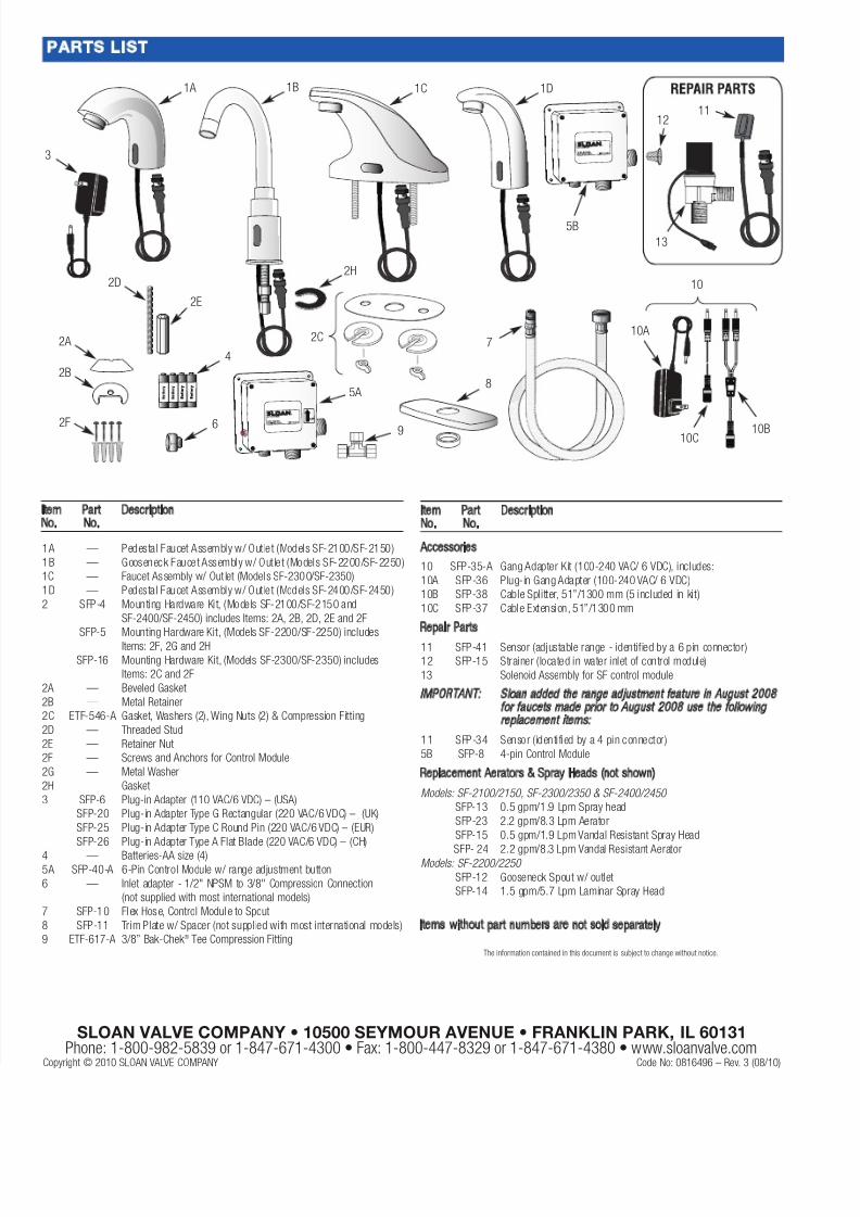
Plug-in Gang Adapter SFP-36
Cable
Splitter SFP-38
Cable Splitter SFP-38
Cable Splitter SFP-38
To
AdditionalFaucets(6 Max.)
A Connect the Adapter and Cables to the Sensor Faucets asshown below.
!!!!IMPORTANT!!!!
DO NOT PLUG IN THE ADAPTER UNTIL ALL
CONNECTIONS ARE MADE
To connect multiple faucets to a single adapter, use the SloanSFP-35-A Gang Adapter Kit (Purchase Separately).
The SFP-35-A Gang Adapter Kit is supplied with cables to connect upto 6 faucets. To connect up to 8 faucets, purchase 2 additionalSFP-38 Cable Splitters separately.
For complete installation, refer to instructions packaged with Gang Adapter Kit.
SFP-35-A Gang Adapter Kit is available in 120 VAC only
7B - GANG ADAPTER INSTALLATION
8 - SET RANGE ADJUSTMENT
9 - SET WATER FLOW TIME-OUT
NOTE: The sensor range is dependent on the distance of your hand or card while the sensor is in range setting mode.
NOTE: If no target is placed in front of the sensor, the sensor range will set to its longest distance.
8/4/2019 0816496
http://slidepdf.com/reader/full/0816496 7/8
7
1. Faucet delivers water in an uncontrolled manner.
A. Faucet is defective. Contact Sloan Valve Company InstallationEngineering Department (see below).
2. Faucet does not deliver any water when Sensor is activated.
INDICATOR: Solenoid valve produces an audible “CLICK.” A. Water supply stop(s) closed. Open water supply stop(s).B. Water strainer in control module is clogged. Close supply stops
and remove water inlet line at control module. Remove, cleanand reinstall strainer and water inlet line. Replace strainer ifrequired.
INDICATOR: Solenoid valve DOES NOT produce an audible“CLICK.”
A. Batteries low (battery powered models). Replace batteries.B. Power failure (adapter powered models). Check power supply.
3. Faucet delivers only a slow flow or dribble when Sensor isactivated.
A. Water supply stop(s) are partially closed. Completely open watersupply stop(s).
B. Water strainer in control module is clogged. Close supply stopsand remove water inlet line at control module. Remove, cleanand reinstall strainer and water inlet line. Replace strainer ifrequired.
C. Aerator is clogged. Remove, clean, and reinstall aerator. Replaceaerator if required.
D.Valve is defective. Contact Sloan Valve Company InstallationEngineering Department (see below).
4. Faucet does not stop delivering water or continues to drip after
user is no longer detected. A. Valve is defective. Contact Sloan Valve Company Installation
Engineering Department (see below).
5. The water temperature is too hot or too cold on a Faucetconnected to hot and cold supply lines.
A. Supply Stops are not adjusted properly. Adjust Supply Stops.
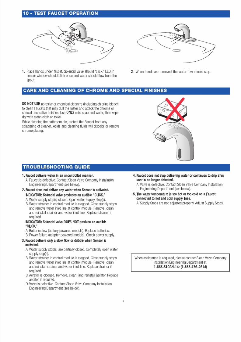
DO NOT USE abrasive or chemical cleaners (including chlorine bleach)to clean Faucets that may dull the luster and attack the chrome orspecial decorative finishes. Use ONLY mild soap and water, then wipedry with clean cloth or towel.
While cleaning the bathroom tile, protect the Faucet from anysplattering of cleaner. Acids and cleaning fluids will discolor or removechrome plating.
When assistance is required, please contact Sloan Valve CompanInstallation Engineering Department at:
1-888-SLOAN-14: (1-888-756-2614)
1. Place hands under faucet. Solenoid valve should “click,” LED insensor window should blink once and water should flow from thespout.
2. When hands are removed, the water flow should stop.
10 - TEST FAUCET OPERATION
CARE AND CLEANING OF CHROME AND SPECIAL FINISHES
TROUBLESHOOTING GUIDE
8/4/2019 0816496
http://slidepdf.com/reader/full/0816496 8/8
SLOAN VALVE COMPANY • 10500 SEYMOUR AVENUE • FRANKLIN PARK, IL 60131Phone: 1-800-982-5839 or 1-847-671-4300 • Fax: 1-800-447-8329 or 1-847-671-4380 • www.sloanvalve.com