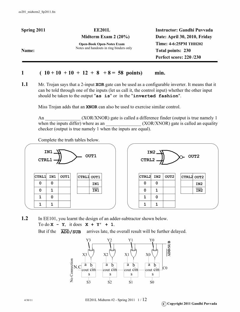
ee201_midterm2_Sp2011.fm 4/30/11 EE201L Midterm #2 - Spring 2011 1 / 12 C Copyright 2011 Gandhi Puvvada Spring 2011 EE201L Instructor: Gandhi Puvvada Midterm Exam 2 (20%) Date: April 30, 2010, Friday Open-Book Open-Notes Exam Time: 4-6:25PM THH202 Name: Total points: 230 Perfect score: 220 /230 1 ( 10 + 10 + 10 + 12 + 8 + 8 = 58 points) min. 1.1 Mr. Trojan says that a 2-input XOR gate can be used as a configurable inverter. It means that it can be told through one of the inputs (let us call it, the control input) whether the other input should be taken to the output "as is" or in the "inverted fashion". Miss Trojan adds that an XNOR can also be used to exercise similar control. An _______________ (XOR/XNOR) gate is called a difference finder (output is true namely 1 when the inputs differ) where as an _______________ (XOR/XNOR) gate is called an equality checker (output is true namely 1 when the inputs are equal). Complete the truth tables below. 1.2 In EE101, you learnt the design of an adder-subtractor shown below. To do X - Y, it does X + Y’ + 1. But if the arrives late, the overall result will be further delayed. IN1 OUT1 CTRL1 IN2 OUT2 CTRL2 IN1 OUT1 CTRL1 0 0 0 1 1 0 1 1 IN2 OUT2 CTRL2 0 0 0 1 1 0 1 1 CTRL1 OUT1 IN1 IN1 CTRL2 OUT2 IN2 IN2 ADD/SUB a b cin s cout a b cin s cout a b cin s cout a b cin s cout X3 X2 X1 X0 Y3 Y2 Y1 Y0 S3 S2 S1 S0 C0 ADD /SUB N.C No Connection Notes and handouts in ring binders only
1.1 Mr. Trojan says that a 2-input XOR gate can be used as a configurable inverter. It means that it can be told through one of the inputs (let us call it, the control input) whether the other input should be taken to the output "as is" or in the "inverted fashion".
Miss Trojan adds that an XNOR can also be used to exercise similar control.
An _______________ (XOR/XNOR) gate is called a difference finder (output is true namely 1 when the inputs differ) where as an _______________ (XOR/XNOR) gate is called an equality checker (output is true namely 1 when the inputs are equal).
Complete the truth tables below.
1.2 In EE101, you learnt the design of an adder-subtractor shown below. To do X - Y, it does X + Y’ + 1. But if the arrives late, the overall result will be further delayed.
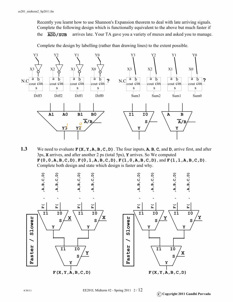
Recently you learnt how to use Shannon's Expansion theorem to deal with late arriving signals.Complete the following design which is functionally equivalent to the above but much faster if the arrives late. Your TA gave you a variety of muxes and asked you to manage.
Complete the design by labelling (rather than drawing lines) to the extent possible.
1.3 We need to evaluate F(X,Y,A,B,C,D). The four inputs, A, B, C, and D, arrive first, and after 3ps, X arrives, and after another 2 ps (total 5ps), Y arrives. So We computed F(0,0,A,B,C,D), F(0,1,A,B,C,D), F(1,0,A,B,C,D), and F(1,1,A,B,C,D).Complete both design and state which design is faster and why.
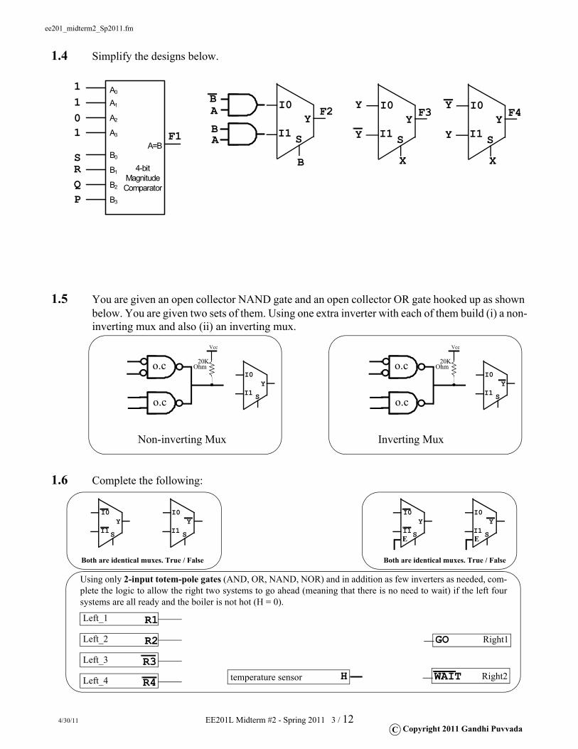
1.5 You are given an open collector NAND gate and an open collector OR gate hooked up as shown below. You are given two sets of them. Using one extra inverter with each of them build (i) a non-inverting mux and also (ii) an inverting mux.
1.6 Complete the following:
A=B
4-bit Magnitude Comparator
A0
A1
A2
A3
B0
B1
B2
B3PQRS
1
01
1 I1
I0Y
S
B
B
B
A
A F2
F1 I1
I0Y
S
X
Y
YF3
I1
I0Y
S
X
Y
YF4
I1
I0Y
S
Non-inverting Mux
Vcc
20KOhmo.c
o.cI1
I0Y
S
Inverting Mux
Vcc
20KOhmo.c
o.c
I1
I0Y
S I1
I0Y
S
Both are identical muxes. True / False
I1
I0Y
S I1
I0Y
S
Both are identical muxes. True / False
E E
Using only 2-input totem-pole gates (AND, OR, NAND, NOR) and in addition as few inverters as needed, com-plete the logic to allow the right two systems to go ahead (meaning that there is no need to wait) if the left foursystems are all ready and the boiler is not hot (H = 0).
State machine design, register-transfer operations, index incrementation to process elements in an array, state transition conditions, clocks spent:
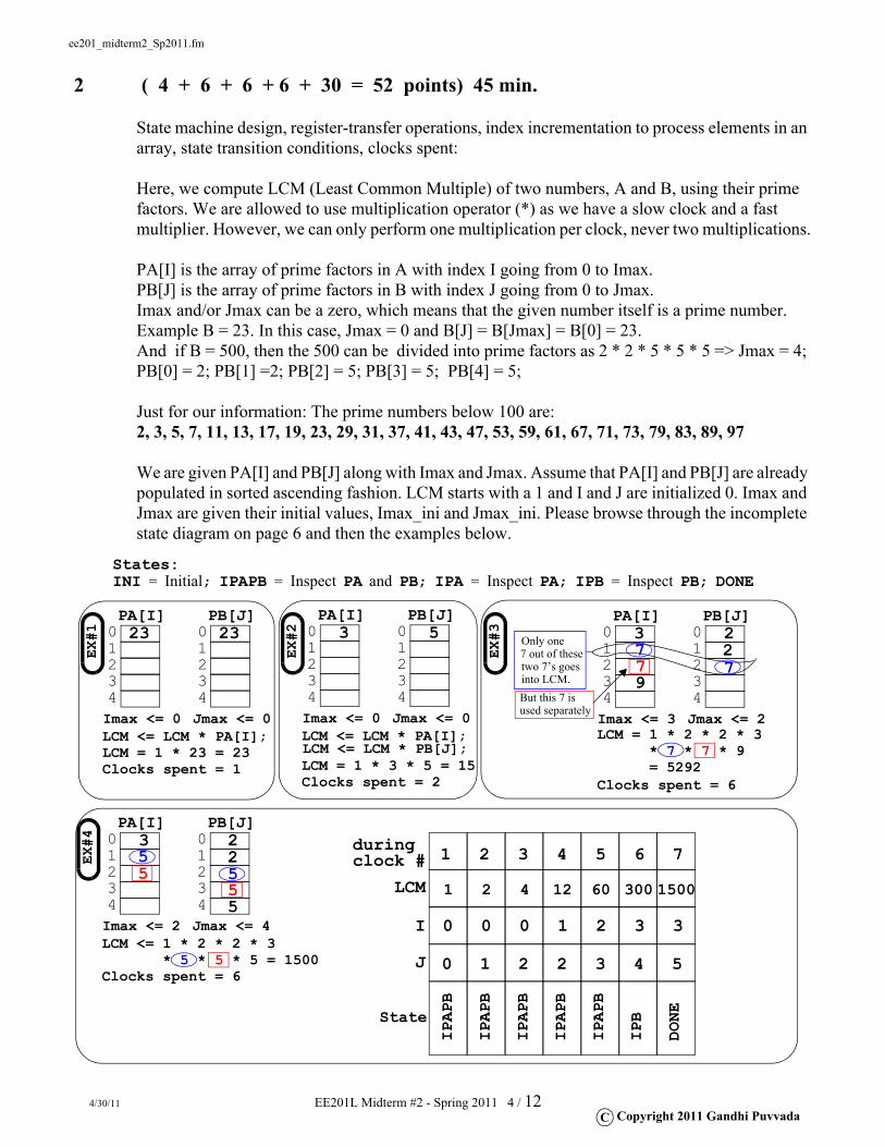
Here, we compute LCM (Least Common Multiple) of two numbers, A and B, using their prime factors. We are allowed to use multiplication operator (*) as we have a slow clock and a fast multiplier. However, we can only perform one multiplication per clock, never two multiplications.
PA[I] is the array of prime factors in A with index I going from 0 to Imax.PB[J] is the array of prime factors in B with index J going from 0 to Jmax. Imax and/or Jmax can be a zero, which means that the given number itself is a prime number. Example B = 23. In this case, Jmax = 0 and B[J] = B[Jmax] = B[0] = 23.And if B = 500, then the 500 can be divided into prime factors as 2 * 2 * 5 * 5 * 5 => Jmax = 4; PB[0] = 2; PB[1] =2; PB[2] = 5; PB[3] = 5; PB[4] = 5;
Just for our information: The prime numbers below 100 are:2, 3, 5, 7, 11, 13, 17, 19, 23, 29, 31, 37, 41, 43, 47, 53, 59, 61, 67, 71, 73, 79, 83, 89, 97
We are given PA[I] and PB[J] along with Imax and Jmax. Assume that PA[I] and PB[J] are already populated in sorted ascending fashion. LCM starts with a 1 and I and J are initialized 0. Imax and Jmax are given their initial values, Imax_ini and Jmax_ini. Please browse through the incomplete state diagram on page 6 and then the examples below.
2.1 Complete the tables for the following examples
2.2 Mr. Bruin wrote the 4 transition conditions for the 4 state transition arrows diverging from the IPAPB state as shown on the side. His design fails in the case of (circle)EX#1 EX#2 EX#3 EX#4 EX#4A EX#4B
2.3 If the current state is IPAPB, and if you happen to be inspecting the last items of both PA and PB arrays, then you can prepare to transit to DONE state (a) certainly (b) if PA[I] < PB[J] (c) if PA[I] > PB[J] (d) if PA[I] == PB[J]Complete the state diagram
3.1 Special counter: The following counter is from the last year (Spring 2010) MT#2 exam with some modification in the bottom 2-bit counter. The first flip-flop is being set on RESET rather than being cleared. There is a new OR gate in place of an earlier AND gate feeding into the D input. Also the value tied to the mux is 001 (=1).
3.2 The above design is modified by removing the OR gate in the bottom counter.
12 pts A0
A1A2
B0B1B2
S0S1S2
Adder
I00I01I02
I10I11I12
Y0Y1Y2
S
Mux
100 1
00
D Q
Register
Q0
Q1
Q2
D Q
D Q
CLK
CLR
LSB
MSB
RESET
D QCLKCLK
RESETSET
Write down the repetitive pattern of the three bit counter starting from reset.________________________________________________________________________________________
D QCLKCLK
RESETCLR
carefully consider when the bottom counter cares for
1
an enable from the top counter and when it does not.
12 pts
A0A1A2
B0B1B2
S0S1S2
Adder
I00I01I02
I10I11I12
Y0Y1Y2
S
Mux
100 1
00
D Q
Register
Q0
Q1
Q2
D Q
D Q
CLK
CLR
LSB
MSB
RESET
D QCLKCLK
RESETSET
Write down the repetitive pattern of the three bit counter starting from reset.________________________________________________________________________________________
D QCLKCLK
RESETCLR
carefully consider when the bottom counter cares for
1
an enable from the top counter and when it does not.
4.1 Memory depth expansion: Build an 32Kx8 using the following 3 chips: -- one 16Kx8 and two 8Kx8 chips
Complete the design below. Add missing labels, address pin labels, wires, and gates.
4.2 State the starting and ending addresses of 32K range of addresses consisting of the system address 12345678H . This 32K range resides in a system of 4 giga (232 = 1 Giga) address space (00000000H - FFFFFFFFH). ___________________________________________Break that 32KB range into two 16KB ranges. (1) ____________________________ (2) ____________________________
4.3 The following range of address in a 1Mega address space (220 = 1 M) is not a natural range: 24000H to 37FFFH . State the size of this range in Kilo-locations (example 333K) ___________
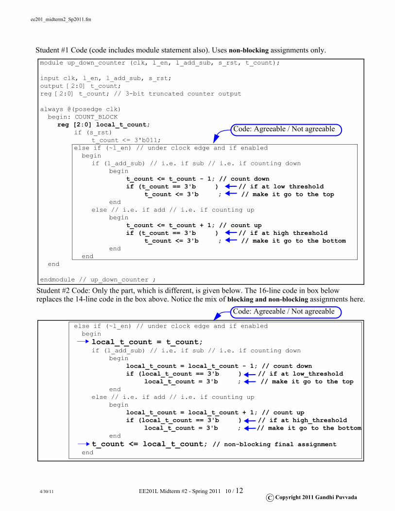
Here, we are designing a special 3-bit UP/DOWN counter which, when enabled, counts from 1 up to 5 (1, 2, 3, 4, 5) and goes back to 1 if it is counting up
or counts from 5 down to 1 (5, 4, 3, 2, 1) and goes back to 5 if it is counting down .
It has an active-high synchronous reset (S_RST) which has the highest priority and forces the counter to go to 3 (the middle of the range). Next priority is for the active-low enable control (L_EN). The L_ADD_SUB stands for ADD/SUB. When it is "0", we are adding 1 means we are counting up. Four student codes are reproduced below, with the 4 constants removed in each.No syntax errors in any one of them. For each of the four codes, either you agree with the code and fill the 4 constants or you fix the code also (only if the code is wrong).
Students #3 and #4 are clever but are also manipulative. Student #3 copied Student #1’s code and modified. Student #4 copied Student #2’s code and modified.
Student #3 and #4 decided to increment the up-down counter by default first (without looking at (l_add_sub). Their idea is that they would increment it by default and fix it if needed (if (l_add_sub) turns out to be true, meaning down-count).
However, they were not sure because one was using non-blocking where as another was using blocking. Write a brief explanation of your understanding of the issues here.
Student #2 Code: Only the part, which is different, is given below. The 16-line code in box below replaces the 14-line code in the box above. Notice the mix of blocking and non-blocking assignments here.
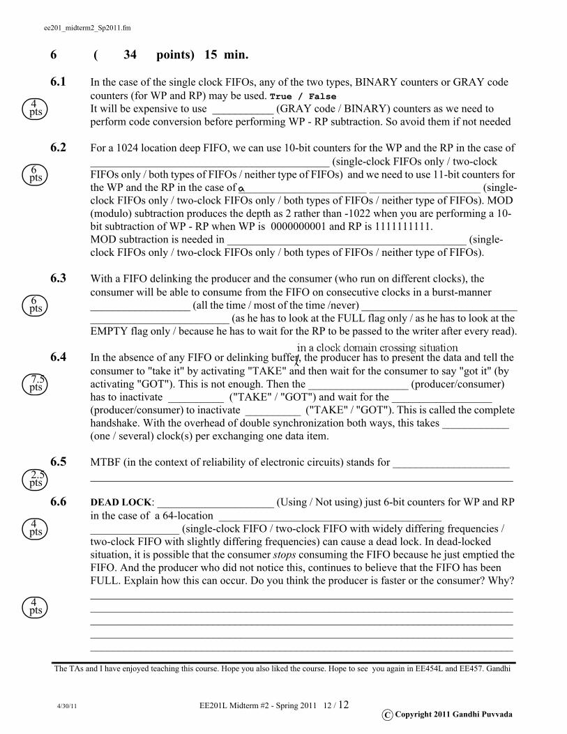
6.1 In the case of the single clock FIFOs, any of the two types, BINARY counters or GRAY code counters (for WP and RP) may be used. True / FalseIt will be expensive to use ___________ (GRAY code / BINARY) counters as we need to perform code conversion before performing WP - RP subtraction. So avoid them if not needed
6.2 For a 1024 location deep FIFO, we can use 10-bit counters for the WP and the RP in the case of ___________________________________________ (single-clock FIFOs only / two-clock FIFOs only / both types of FIFOs / neither type of FIFOs) and we need to use 11-bit counters for the WP and the RP in the case of _______________________ ____________________ (single-clock FIFOs only / two-clock FIFOs only / both types of FIFOs / neither type of FIFOs). MOD (modulo) subtraction produces the depth as 2 rather than -1022 when you are performing a 10-bit subtraction of WP - RP when WP is 0000000001 and RP is 1111111111. MOD subtraction is needed in ___________________________________________ (single-clock FIFOs only / two-clock FIFOs only / both types of FIFOs / neither type of FIFOs).
6.3 With a FIFO delinking the producer and the consumer (who run on different clocks), the consumer will be able to consume from the FIFO on consecutive clocks in a burst-manner __________________ (all the time / most of the time /never) _____________________________________________________ (as he has to look at the FULL flag only / as he has to look at the EMPTY flag only / because he has to wait for the RP to be passed to the writer after every read).
6.4 In the absence of any FIFO or delinking buffer, the producer has to present the data and tell the consumer to "take it" by activating "TAKE" and then wait for the consumer to say "got it" (by activating "GOT"). This is not enough. Then the __________________ (producer/consumer) has to inactivate __________ ("TAKE" / "GOT") and wait for the __________________ (producer/consumer) to inactivate __________ ("TAKE" / "GOT"). This is called the complete handshake. With the overhead of double synchronization both ways, this takes ____________ (one / several) clock(s) per exchanging one data item.
6.5 MTBF (in the context of reliability of electronic circuits) stands for _________________________________________________________________________________________________
6.6 DEAD LOCK: _____________________ (Using / Not using) just 6-bit counters for WP and RP in the case of a 64-location ________________________________________ ________________ (single-clock FIFO / two-clock FIFO with widely differing frequencies / two-clock FIFO with slightly differing frequencies) can cause a dead lock. In dead-locked situation, it is possible that the consumer stops consuming the FIFO because he just emptied the FIFO. And the producer who did not notice this, continues to believe that the FIFO has been FULL. Explain how this can occur. Do you think the producer is faster or the consumer? Why?____________________________________________________________________________________________________________________________________________________________________________________________________________________________________________________________________________________________________________________________________________________________________________________________
4 pts
6 pts
6 pts
7.5 pts
2.5 pts
4 pts
4 pts
The TAs and I have enjoyed teaching this course. Hope you also liked the course. Hope to see you again in EE454L and EE457. Gandhi