23
1 2 GRPS 3 4 MIX

1
44
1
1 2 GRPS 3 4 MIX
SPIRIT FOLIO RAC PAC
Connections
The Controls in Detail -
Technical Specifications
System Block Diagram
1
3
6
8
10
13
15
Mono Input
Stereo Input
Stereo Returns
Master Section

Introduction
Thank you for buying a SPIRIT FOLIO RAC PAC mixer, brought to you with pride by the SPIRIT team of Peter, Graham,Martin, Ian, Stuart, Peter, George, Colin, James, Chris, Mukesh, Andy, Candy and Simon. We hope you have as muchfun as we did!
Owning a SPIRIT console brings you the expertise and support of one of the industrys leading manufacturers and theresults of over 20 years experience supporting some of the biggest names in the business.
Built to the highest standards using quality components, FOLIO RAC PAC is designed to be as easy to use as possible,but some time spent NOW, looking through this manual and getting to know your new mixer will give you lots of helpfultips and confidence, away from the pressures of an important session. Dont be afraid to experiment to find out howeach control affects the sound - this will only extend your creativity and help you to get the best from your mixer.
SAFETY PRECAUTIONS
For your own safety and to avoid invalidation of the warranty please read thissection carefully.
The FOLIO RAC PAC desk must only be connected through the Power SupplyUnit supplied.
The wires in the mains lead are coloured in accordance with the following code:
Green and Yellow: Earth
Blue: Neutral
Brown: Live
As the colours of the wires in the mains lead may not correspond with the coloured markings identifying the terminalsin your plug, proceed as follows:
•• The wire which is coloured Green and Yellow must be connected to the terminal in the plug which is marked withthe letter E or by the earth symbol.
•• The wire which is coloured Blue must be connected to the terminal in the plug which is marked with the letter Nor coloured Black.
•• The wire which is coloured Brown must be connected to the terminal in the plug which is marked with the letter Lor coloured Red.
Ensure that these colour codings are followed carefully in the event of the plug being changed.
The power supply contains no user-serviceable parts. Refer all servicing to aqualified service engineer, through the appropriate Soundcraft dealer.
SPIRIT FOLIO RAC PAC1

ConnectORS
Left Signal
Right Signal
Ground
Headphones
Signal (+ve)
Ground Sense (-ve)
Screen
Signal (+ve)
Gnd/Screen
Gnd/Screen
Signal Send
Signal Return
Gnd/Screen
Tip
Ring Sleeve
Inserts Mix OutputsGroup OutputsAux Outputs
Direct Outputs
Hot (+ve)
Cold (-ve)
Gnd/Screen
Signal
Gnd/Screen
Gnd/Screen
Tip
Ring Sleeve
Unbalanced3 pole Jack
Unbalanced MicXLR
Balanced MicXLR
Balanced3 pole Jack
2. Hot(+ve)
3. Cold(-ve)1. Screen 1. Screen
2. Hot(+ve)
Link 3to 1
INPUTS, 2 TRACK RETURNS & FX RETURNS
(Note: All inputs are balanced, but unbalanced sources may be used as shown)
POWER CONNECTOR PINOUTS
(viewed from cable end)
Pin 1Pin 2Pin 3Pin 4
20V ACn/c0V20V AC
1
3 2
4
R
2SPIRIT FOLIO RAC PAC

ConNections - Input Channels
R
SPIRIT FOLIO RAC PAC3

CONNECTIONS - MASTER SECTION
R
4SPIRIT FOLIO RAC PAC

INITIAL SETTING UP
You will probably use your SPIRIT FOLIO RAC PAC with a wide range of different types of sound source, and these willbe at varying signal levels. It is important to set the GAIN of the inputs correctly to give the best performance.
Set up the individual Mono input channels as follows:
•• Plug in the chosen source (usually the MIC input for mics and the LINE input for anything else). Plug in phantompowered mics before switching the phantom power on. Set the channel fader fully down.
•• Set the Group and Master Faders at 0 and GROUPS TO MIX pressed.
•• Select MIX to C/Room & Phones.
•• Check that SOLO MODE is released.
•• Release the channel routing switches to route to Groups 1-2
•• Provide the chosen source with a typical signal level and press the latching PFL button by the fader. The level ofsignal will be shown on the right-hand Bargraph Meter (the Left meter will be switched off when the PFL button isdown).
•• Adjust the input GAIN until the meter is just reaching the amber LED (0dB) at a typical maximum source level witha steady signal. If the source signal is rich in high-level transients (e.g. drums) a rather higher meter reading of+6/+9 will be needed to achieve an equivalent average level. This leaves enough headroom to cope with peaksin the signal without distortion.
•• Adjust each input channel in the same way.
•• If you find that you cannot set a reasonable level within the range of the GAIN control when using a MIC inputon the Mono channels, try the LINE input instead.
Stereo inputs 11-14 do not have a GAIN control, since the typical source for these inputs will be external tape machinesor effects units which have a much more predictable signal level. Set the +4/-10 switch to +4 (released) initially, andcheck the input level with the PFL switch as decribed above. If the level is too low, switch to the -10 input setting.
You will now have initial settings for each of the input sources and are ready to start building a mix.
•• Connect your power amplifiers and speakers and set the gain of the amplifiers to about 70%.
•• Move the individual channel faders gradually to the required working level, listening carefully for any hint offeedback or overload. You may find that the input gain settings will need to be edged back slightly as the mix isbuilt up.
•• Listen carefully for the characteristic sound of feedback. If you cannot achieve a satisfactory input level settingwithout feedback, adjust microphone and speaker positions and try again.
Careful microphone placement and the choice of a suitable type of microphone is important for vocals. The aim shouldbe to place the microphone as close as possible to the source, to cut out unwanted surrounding sounds. This allows alower gain setting on the mixer and helps to avoid feedback. You will also find that a well-placed microphone will notneed any appreciable equalisation.
SPIRIT FOLIO RAC PAC5

SETTING UP FOR RECORDING
While the connections to the FOLIO RAC PAC for PA work are quite straightforward, recording is rather moredemanding because the mixer is not only required to mix down input signals but also to provide a monitor mix for artiststo hear previously recorded tracks when overdubbing new parts. Two typical set-ups are as follows:
Stereo Recording to DAT
•• Connect input sources and set gain as described above. Route the channels via the groups to Mix. Connect theMix L/R outputs to the tape inputs.
•• Connect the tape outputs to the 2TK Returns. Set the level control on these returns at zero.
•• Connect a monitor amplifier for foldback headphones or a monitor speaker to the Aux 1 output. Set the amplifiervolume to a normal listening level.
•• Use the Aux 1 send controls on the tape channels to set up a mono monitor mix. (make sure that all other Aux 1controls are fully off)
•• If a compressor is to be used on an individual source, connect this to the channel insert point.
•• Connect any effects required using Aux 2-6, and return them to the mix on the FX Returns or unused Stereo Returnsto allow the effect to be balanced with the original source.
It is important to match the input and output levels of your mixer and recording device to avoid distortion and create thebest recording.
•• Set the recording level as recommended for your recording device, feeding a suitable signal from the Group orMix outputs.
•• Monitor the signal going to the recorder by selecting the appropriate source on the C/Room & Phones sourceselect switches. Gradually increase the 2TK return level control while alternately switching between the monitorsource and 2TK until no change in level is detected.
8 Track Recording
•• Connect input sources and set gain as described above. Set the C/Room & Phones source to MIX.
•• Check that the GROUPS TO MIX button is released.
•• Connect the direct outputs on the eight required channels to the recorder inputs.
•• Connect a monitor amplifier for foldback headphones or a monitor speaker to the Aux 1 or Aux 2 (set PRE) output.Set the amplifier volume to a normal listening level.
•• If a compressor or other effect is to be used on an individual source, connect this to the channel insert point.
•• Connect the recorder outputs to the 4 stereo returns. Route the returns to MIX. Alternatively, if only one or twotracks are being recorded, the machine outputs could be brought back to spare mono inputs and routed to a groupfor monitoring.
The C/Room & Phones will now be listening to the monitor mix, or, if selected to Groups will carry the source mix. Notethat the balance of these mixes will be essentially the same.
This configuration allows a very high quality recording to be made, with the signal passing through the shortest signalpath. The mixer may be reconfigured for a separate mix-down session to a stereo master at a later date.
6SPIRIT FOLIO RAC PAC

THE CONTROLS IN DETAIL
MONO INPUT CHANNELS 1-10
1 TRIM
The TRIM control sets how much of the source signal is sent to the rest of the mixer. Toohigh, and the signal will distort as it overloads the channel and causes clipping. Toolow, and the level of any background hiss will be more noticeable and you may not beable to get enough signal level to the output ofthe mixer. This is shown in the diagram on theright:
Setting the knob to the "+4U" mark gives unitygain on the LINE input for nominal +4dBusources, which will be suitable for mostprofessional equipment. Note that somesound equipment, particularly that intendedfor semi-professional use, operates at a lowerlevel (-10dBV) and will therefore need a highergain setting to give the same output level. Asecond point marked "-10U" indicates theunity gain setting for -10dBV sources.
See "Initial Setting Up" to learn how to set theGAIN correctly.
MIC INPUT
The mic input accepts XLR-type connectors and is designed to suit a wide range ofBALANCED or UNBALANCED low-level signals, whether from delicate vocals requiringthe best low-noise performance or close-miked drum kits needing maximum headroom.Professional dynamic, condenser or ribbon mics are best because these will be LOWIMPEDANCE. While you can use low-cost HIGH IMPEDANCE mics, you do not get thesame degree of immunity to interference on the microphone cable and as a result thelevel of background noise may be higher. If you turn the PHANTOM POWER on (topright-hand side of the mixer) the socket provides a suitable powering voltage forprofessional condenser mics.
DO NOT use unbalanced sources with the phantom power switched on. The voltageon pins 2 & 3 of the XLR connector may cause serious damage.
Unplug any mics if you want to use the corresponding LINE Input to avoid the loadpresented by the mic from affecting the Line Input gain.
LINE INPUT
Accepts 3-pole A gauge (TRS) jacks. Use this input for sources other than mics, suchas keyboards, drum machines, synths, tape machines or guitars. The input isBALANCED for low noise and immunity from interference, but you can useUNBALANCED sources by wiring up the jacks as shown in the "Connectors" sectionearlier in this manual, although you should then keep cable lengths as short as possibleto minimise interference pick-up on the cable. Unplug anything in the MIC input if youwant to use this socket.
2 100Hz HI-PASS FILTER
Pressing this switch reduces the level of bass frequencies only, and is a real bonus forsuch a small mixer. Use this in live PA situations to reduce stage rumble or poppingfrom microphones.
5-6
100
10
1
2
3
4
5
6
7
8
If the signal level is too low it may be maskedby the noise.
Signal Noise
If the signal level is too high, clipping distortionmay occur.
ClippedSignal
Noise
SPIRIT FOLIO RAC PAC7

3 EQUALISER
The Equaliser (EQ) allowsprecise manipulation of thesound, particularly toimprove the sound ofmicrophone sources wherethe original signal is often farfrom ideal due to pooracoustics or restrictions onwhere to place microphonesand where slight boosting orcutting of particular voicefrequencies can really makea difference to clarity. The EQ allows enough control to improve, for instance, badrecordings or the precision to gently enhance vocal or live instrument tracks. There arethree sections, HF, MID and LF giving the sort of control usually only found on muchlarger mixers. The EQ knobs can have a dramatic effect, so use them sparingly andlisten carefully as you change any settings so that you get to know how they affect thesound.
HF EQ
Turn to the right to boost high (treble) frequencies by up to 15dB at 12kHz, addingcrispness to cymbals, vocals and electronic instruments. Turn to the left to cut thesefrequencies by up to 15dB, reducing hiss or over-emphasis of high-frequencyconsonants, which can occur with certain types of microphone. Set the knob in thecentre-detented position when a flat response is required.
MID EQ
There are two knobs which work together to form a SWEPT MID EQ. The lower knobprovides 15dB of boost and cut, just like the HF EQ knob, but the frequency at whichthis occurs can be set by the upper knob over a range of 250Hz to 6kHz. This allowssome truly creative improvement of the signal in live situations, because this mid bandcovers the range of most vocals. Listen carefully as you use these controls together tofind how particular characteristics of a vocal signal can be enhanced or reduced. Setthe lower knob to the centre-detented position when not required.
LF EQ
Turn to the right to boost low (bass) frequencies by up to 15dB at 60Hz, adding warmthto vocals or extra punch to synths, guitars and drums. Turn to the left to cut lowfrequencies by up to 15dB for reducing hum, stage rumble or to improve a mushy sound.Set the knob to the centre-detented position when not required.
4 AUX SENDS
These controls route the input channel signal to any one or more of six Auxiliary whichare used to set up separate mixes for FOLDBACK, EFFECTS or recording, and thecombination of all the Aux Sends is mixed to the corresponding Aux Output at the rearof the mixer. The controls are specially chosen to give a particularly smooth and usefulcontrol range all round the scale while still maintaining nearly 90dB cut-off when turnedanticlockwise.
Aux 1 is always PRE-FADE and pre-EQ which is ideal for Foldback or Monitor feedswhere the send needs to be independent of the fader so that, for instance, the mix toartists headphones is not affected by changes in fader level.
20.0
15.0
10.0
5.0
0.0
-5.0
-10.0
-15.0
-20.020 1k 10k 20k100
dB
Frequency/Hz
TYPICAL EQUALISER RESPONSE
LF SWEPT MID HFBOOST
CUT
8SPIRIT FOLIO RAC PAC

Aux 3 and 4 are always POST-FADE, ideal for Effects where it is useful for the Aux Sendto fade up and down with the fader. For flexibility, the Master Section AUX2 PRE switchallows you to switch AUX 2 from post- to pre-fade across the whole mixer as required.
Aux 5 & 6 are identical to Aux 3 & 4 and may be selected as an alternative by pressingthe 5-6 switch.
Leave all of the knobs turned fully left when not in use.
5 PAN
This control sets the amount of the channel signal feeding the pairs of Groups, allowingyou to move the source smoothly across the stereo image. When the control is turnedfully right or left you are able to place the signal at unity gain to either Groups 2 & 4or 1 & 3 respectively.
6 ROUTING
This switch selects either Groups 1 & 2 (switch released) or Groups 3 & 4 (switch pressed)as the destination for the channel signal after it has passed through the PAN control.
7 FADER
The linear FADER gives you smooth control of the overall signal level in the channelstrip, allowing precise balancing of the various source signals being mixed to the MasterSection. You get most control when the input GAIN is set up correctly, giving a normalfader position around the 0 mark, generous control range below and some gain inhand above the mark when you need that little bit extra. See the Initial Setting Upsection for help in setting a suitable signal level.
Note that the post-fader signal is available as a DIRECT OUTPUT from the channel tofeed tape tracks or other external equipment.
8 SOLO
The latching SOLO switch has two distinctive modes of operation, depending on theposition of the master section SOLO MODE switch. When this switch is released(AFL/PFL) all channel SOLO switches function as PFL (Pre-Fade-Listen). When SOLOMODE is pressed (IN PLACE) all SOLO switches become a SOLO-IN-PLACE facility.
In PFL/AFL mode, pressing the SOLO switch feeds the pre-fade channel signal to themonitor output, headphones and Right Bargraph Meter, replacing the selected source.You use this switch to listen to a channel signal without affecting the mixer outputs, tocheck the signal quality or simply to check that it is there!
In SOLO mode, pressing one or more channel SOLO switches mutes all other channelsleaving the selected channels alone in the mix. The Stereo Returns or FX Returns arenot muted, and this allows the selected channels to be monitored in their true stereoposition, including any effects which may have been added.
The associated PEAK LED indicator normally warns when an excessively high signallevel is present in the channel. The signal is sampled just after the EQ section and theLED will light approximately 4dB before clipping. This point is post-insert, and willtherefore take into account the effect of any equipment connected to the Insert jack.
When the SOLO switch is pressed the LED lights continuously to show which channelsare being monitored.
5-6
100
10
1
2
3
4
5
6
7
8
SPIRIT FOLIO RAC PAC9

5-6
13 14
1
2
3
4
5
6
7
STEREO INPUT CHANNELs 11-14
These inputs accept 3-pole A gauge (TRS) jacks. Use these inputs for sources such askeyboards, drum machines, synths, tape machines or as returns from processing units.The inputs are BALANCED for low noise and immunity from interference, but you canuse UNBALANCED sources by wiring up the jacks as shown in the "CONNECTIONS"section earlier in this manual, although you should then keep cable lengths as short aspossible to minimise interference pick-up.
If you wish to use the channel with a mono source, plugging into the Left jackautomatically feeds the source to both sides of the channel.
1 INPUT +4/-10
Most professional equipment uses input and output levels of +4dBu, butsemi-professional tape machines or hi-fi systems use a lower level of -10dBV. This switchallows you to match the sources connected to the Stereo input jacks to either standard,which is important to ensure the best possible sound quality. If you are not sure whichinput level is appropriate, start with the switch UP to select +4dBu. If you are unableto achieve an adequate signal level (even with the fader at maximium), press the switchin for -10dBV.
2 EQUALISATION
HF EQ
Turn to the right to boost high (treble) frequencies, adding crispness to percussion fromdrum machines, synths and electronic instruments. Turn to the left to cut thesefrequencies, reducing hiss or excessive brilliance. Set the knob in the centre-detentedposition when not required. The control has a shelving response giving 12dB of boostor cut at a fixed frequency of 12kHz.
LF EQ
Turn to the right to boost low (bass) frequencies, adding extra punch to synths, guitarsand drums. Turn to the left to reduce hum, boominess or improve a mushy sound. Setthe knob to the centre-detented position when not required. The control has a shelvingresponse giving 12dB of boost or cut at a fixed frequency of 60Hz.
3 AUX SENDS
These controls route a mono sum of the channel signal to any one or more of six Auxiliarywhich are used to set up separate mixes for FOLDBACK, EFFECTS or recording, andthe combination of all the Aux Sends is mixed to the corresponding Aux Output at therear of the mixer. The controls are specially chosen to give a particularly smooth controlrange at the lower end of the scale where it is most needed - quite unique on a mixerof this type.
Aux 1 is always PRE-FADE which is ideal for Foldback or Monitor feeds where the sendneeds to be independent of the fader so that, for instance, the mix to artists headphonesis not affected by changes in fader level.
Aux 3 and 4 are always POST-FADE, ideal for Effects where it is useful for the Aux Sendto fade up and down with the fader. For flexibility, the Master Section AUX2 PRE switchallows you to switch AUX 2 from pre- to post-fade across the whole mixer as required.
Aux 5 & 6 are identical to Aux 3 & 4 and may be selected as an alternative by pressingthe 5-6 switch.
Leave all of the knobs turned fully left when not in use.
10SPIRIT FOLIO RAC PAC

5-6
13 14
1
2
3
4
5
6
7
4 BALANCE
This control sets the amount of the channel signal feeding the pairs of Groups, allowingyou to balance the source in the stereo image. When the control is turned fully right orleft you feed only that side of the signal to the Groups selected by the Routing switch(see below).
5 ROUTING
This switch selects either Groups 1 & 2 (switch released) or Groups 3 & 4 (switch pressed)as the destination for the channel signal after it has passed through the BAL control.
6 FADER
The linear FADER gives you smooth control of the overall signal level in the channelstrip, allowing precise balancing of the various source signals being mixed to the MasterSection. It is important that the input level is set correctly with the +4/-10 switch to givemaximum travel on the fader which should normally be used at around the 0 mark.See the Initial Setting Up section for help in setting a suitable signal level.
7 SOLO
The latching SOLO switch has two distinctive modes of operation, depending on theposition of the master section SOLO MODE switch. When this switch is released(AFL/PFL) all channel SOLO switches function as PFL (Pre-Fade-Listen). When SOLOMODE is pressed (IN PLACE) all SOLO switches become a SOLO-IN-PLACE facility.
In PFL/AFL mode, pressing the SOLO switch feeds a mono sum of the pre-fade channelsignal to the monitor output, headphones and Right Bargraph Meter, replacing theselected source. You use this switch to listen to a channel signal without affecting themixer outputs, to check the signal quality or simply to check that it is there!
In SOLO mode, pressing one or more channel SOLO switches mutes all other channelsleaving the selected channels alone in the mix. The Stereo Returns or FX Returns arenot muted, and this allows the selected channels to be monitored in their true stereoposition, including any effects which may have been added.
When the SOLO switch is pressed the associated LED lights continuously to show whichchannels are being monitored.
SPIRIT FOLIO RAC PAC11

1
44
1
1
2
3
4
5
STEREO RETURNS
There are four Stereo Returns, which have similar controls but different routingconfigurations to provide the maximum flexibility. Each Return has anunbalanced stereo input on 3-pole A gauge (TRS) jacks. If a mono source isto be used, plugging into the Left jack automatically feeds the signal equally toboth sides of the Return.
1 LEVEL
The LEVEL control sets the overall signal level, and enough gain is available tomatch both +4dBu and -10dBV sources. Rotation clockwise increases the gainof the input.
2 AUXILIARY SENDS
Each Return may access Aux 1 (Pre-fade) and one of the post-fade sends.Returns A & C feed to Aux 3 and Returns B & D feed to Aux 4. The controlsshould be turned fully anticlockwise when not in use.
3 BALANCE
This control sets the amount of the channel signal feeding the pairs of Groupsor Mix, allowing you to balance the source in the stereo image. When the controlis turned fully right or left you feed only that side of the signal to the destinationselected by the Routing switch (see below).
4 PFL
When the PFL (Pre-Fade-Listen) switch is pressed a mono sum of the pre-fadesignal is fed to the headphones or monitor output, replacing the selected source.The PFL LED on the Master section illuminates to warn that the headphones,monitor and right bargraph meter are now responding to the PFL/AFL selection.
5 ROUTING
This switch selects either a pair of Groups (switch released) or Mix (switchpressed) as the destination for the Stereo Return signal after it has passed throughthe BAL control. Returns A & B route to Groups 1 & 2, and Returns C & D routeto Groups 3 & 4. The left return signal feeds the odd-numbered Group or MixLeft, while the right return signal feeds the even-numbered Group or Mix Right.
12SPIRIT FOLIO RAC PAC
1
44
1
1 2 GRPS 3 4 MIX
11
10
7
4
6
3
2
1
12
5
9
8
SPIRIT FOLIO RAC PAC13

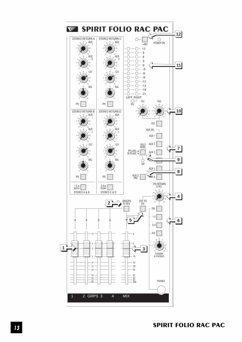
MASTER SECTION
1 GROUP FADERS
Four Group FADERS set the overall level of the Groups, allowing the combined control of a selected number of inputsources. The Groups may feed external equipment directly through the ground compensated Group output jacks, ormay be mixed together to the stereo Mix output (see below). The faders should normally be set close to the 0 mark ifthe input GAIN settings have been correctly set, giving plenty of control below the mark and additional gain in hand ifrequired.
2 GROUPS TO MIX
Pressing this switch routes all Groups to the main stereo Mix. Groups 1 & 3 feed Mix Left and Groups 2 & 4 feed MixRight.
3 MIX FADER
A stereo fader controls the output level of the stereo Mix. The outputs are ground compensated 3-pole A gauge (TRS)jacks. The Mix Left and Right signal paths have pre-fade INSERT points which provide a means of diverting the signalto an external processing unit such as a compressor or limiter. Inserting a jack into the insert breaks the signal path andallows the INSERT SEND (on the tip of the jack) to feed the input of the external unit and the INSERT RETURN (on thering of the jack) to receive the corresponding output. Note that if the tip and ring of the jack are shorted together thesignal path remains unbroken and the Insert may then be used as a way of tapping off the Mix signal before the fader.
4 2 TRACK (2TK) RETURN LEVEL
The unbalanced 2TK return jacks are an ideal place to connect the playback of a tape machine, without using up anyof the LINE inputs. This control sets the level of playback signal fed either to the MIX (when 2TK TO MIX is pressed) orthe headphones or monitor output, when 2TK is pressed. When set fully clockwise the inputs will be matched to -10dBVsources, or will suit a +4dBu source with the LEVEL control at a lower setting. A mono source may be fed automaticallyto both left and right by plugging into the Left return jack only.
The 2TK RETURN is also the best way of connecting a tape or CD player to feed pre-show music to a PA rig, since thisleaves all input settings unaltered. It can also serve as the return from an Effects unit to save using up Line Inputs.
5 2TK TO MIX
Press this switch to route the 2TK RETURN signal directly to the mix outputs. Adjust the input level with the 2TK RETURNLEVEL control. The 2TK Return signal will now be present at the Mix outputs, at a level set by the Master Fader.
6 C/ROOM & PHONES SECTION
The rotary control sets the output level to the MONITOR LEFT & RIGHT outputs. If HEADPHONES are plugged into thePHNS jack the Monitor outputs are cut off, and the knob then sets the headphone listening level. When the PHONESare unplugged the Monitor output is restored.
The section may listen to a choice of sources: 2TK Return, Groups and Mix as selected on the four switches. The selectedsource is also displayed on the bargraph meters.
If any PFL or AFL switch is pressed the selected signal is replaced by the appropriate PFL or AFL signal, which will alsobe displayed on the right bargraph meter.
14SPIRIT FOLIO RAC PAC

1
44
1
1 2 GRPS 3 4 MIX
11
10
7
4
6
3
2
1
12
5
9
8
SPIRIT FOLIO RAC PAC15

AUXILIARY MASTERS
The Master section houses the summing amplifiers for each of the Auxiliary Send , and feeds the signal via groundcompensated output amplifiers to the Auxiliary Output jacks.
7 AUX AFL
The individual outgoing Aux signals may be monitored on the control room outputs or headphones by pressing theappropriate AFL (After-Fade-Listen) switch. The selected signal is also displayed on the right bargraph meter.
8 AUX 2 PRE
Aux 2 is normally post-fade, but for flexibility it may be switched to pre-fade by pressing the AUX 2 PRE switch. Thissimultaneously affects all Aux 2 sends across the mixer.
9 SOLO MODE
All channel SOLO switches are normally a non-destructive PFL (Pre-Fade-Listen). When SOLO MODE is pressed,SOLO-IN-PLACE mode is activated. If any channel SOLO switch is pressed the SIP LED will illuminate and all otherchannels (but not Stereo, FX or 2TK Returns) are cut, leaving the selected channel, complete with effects in the mix. WhileSOLO-IN-PLACE is active, if any PFL or AFL switch is pressed the C/Room & Phones and meters will silently switch overto monitor the selected signal, but the mix output will remain. Releasing the AFL/PFL re-instates the solo signal.
10 FX RETURNS
The unbalanced FX Return jacks are an ideal place to connect the output of an effects unit, without using up any of theLINE inputs. This control sets the level of the signal fed directly to the MIX. When set fully clockwise the inputs will bematched to -10dBV sources, or will suit +4dBu sources with the controls at a lower setting. A mono source may be fedautomatically to both left and right by plugging into the Left return jack only. A CUT switch mutes both FX Returns ifrequired.
11 BARGRAPH METERS
The three colour BARGRAPH METERS have a PEAK response and normally follow the Monitor selection, giving you aconstant warning of excessive peaks in the signal which might cause overloading. The fast attack of the meters meansthat a signal with high level transients (e.g. kick drum) will tend to give a higher reading than a less dynamic signal (e.g.a synth) at the same level. You should therefore aim for an average reading of +6/+9 if the mix contains a highproportion of high level transients and a lower reading of around 0 for steadier signals with the Master Faders atabout the 0 mark.
If the output level is too low and hardly registering at all on the meters, the level of background noise may becomesignificant. In this case check that input levels and gain settings are correct (see the section -- Initial Setting Up)
When an AFL or PFL switch is pressed the selected meter signal is muted and the right meter will display the selectedPFL/AFL signal.
N.B. The 0 position on the meters corresponds to +4dBu at the selected output.
12 PHANTOM POWER
Many professional condenser mics need PHANTOM POWER, which is a method of sending a powering voltage downthe same wires as the mic signal. Press the switch to enable the +48V power to the MIC inputs on channels 1-10.
DO NOT turn on the phantom power when using unbalanced mics which may be damaged by the voltage applied topin 2 & 3 of the mic input XLR.
Note: Mics should always be plugged in before switching the Phantom Power ON.
16SPIRIT FOLIO RAC PAC

R
Applications
Multitrack Recording
This example illustrates how Rac Pac may be set up for multitrack recording to eight tracks. Individual instrument orvocal tracks are recorded on Digital Multitracks by connecting the channel Direct Outputs to the tape inputs. The outputsfrom the Multitrack are brought back on the Stereo Returns (or spare mono channels if only one or two tracks are beingrecorded). A compressor is included on the insert of one of the vocal channels. An Artists Phones mix is derived fromAux 1 (or Aux 2 selected pre-fade).
SPIRIT FOLIO RAC PAC17

Stereo Public Address
In this basic PA set-up, various sources are connected to the inputs, microphones to Mic inputs and keyboards etc. toLine inputs. Note that some guitars will not produce sufficient level for a direct connection, and will require a DirectInjection (DI) box connected via the microphone input. The mic channel has a compressor/limiter included in the insertpoint and a feed to a reverb unit from the direct output. The reverb output is brought back to the mix on FX Return 1.The output is taken from Mix L & R and connected to the speakers via a suitable power amplifier. A compressor/limiter(or graphic equaliser if required) is included in the Mix Inserts, and a cassette machine connects to the 2TK Return toprovide interval music. The Groups may be used to combine several inputs under the control of a single fader beforemixing to the L & R outputs.
R
18SPIRIT FOLIO RAC PAC

Relocating the connector panel
The connector panel is fitted as standard to the rear of the frame, allowing the mixer to be used as a free-standing,desktop unit. If the mixer is to be rack-mounted, it may be found more convenient to move the connector panel to theoptional position in the base of the frame, opposite the front panel, giving rear access to connectors when fitted in therack. A cover plate is mounted in the alternative position, and this is swapped with the connector panel in astraightforward procedure described below:
1 Carefully lay the mixer face down on a flat surface provided with some protective padding. During the followingsteps take care not to apply excessive pressure or damage the control knobs.
2 Using a cross-head screwdriver remove the four screws "A" (2 each side) fixing the cover plate through the sidepanels of the mixer.
3 Release the cover plate by next removing the six screws "B" fixing the plate to the basepanel and connector panel. Lay the coverplate to one side.
4 Now remove the three screws "D" fixing theconnector panel to the top edge of themixer. The connector panel will still besupported by the fixings through the sidepanels.
5 Loosen the four screws "C" fixing theconnector panel to the side panels. Now,supporting the connector panel with onehand, remove the four screws completely,freeing the panel.
6 Swapping the supporting hand, rotate the panel backwards, taking care not to strainor snag any of the ribbon cables, so that thebottom edge now rests on the flange of thebase panel, and loosely fit the screws ("A",4 off) once again through the side panels.
7 Pick up the cover plate and, turning itlengthways locate it in the position originallyoccupied by the connector panel. (Note thatthe cover plate has one flat edge, and onefolded flange. The folded edge ALWAYSfaces the back corner of the mixer.)
8 Loosely fit the four screws "C" through the side panels, three screws "D" at the top edge, and six screws "B" fixing the connector panel.
9 Once you are satisfied that the panels are seated correctly, tighten all screws firmly.
This completes the relocation of the connector panel. Simply reverse the procedure if you wish to return the panel to theoriginal position.
MSPS
MSPS
MSPS
MSPS
MSPSMSPS
MSPSMSPS
D
C
C
B
B
A
A
Cover Panel
Connector P
anel
Front Panel
SPIRIT FOLIO RAC PAC19

Technical Specification
Output Noise Typical Group Output,Input faders down -87dBu
Group fader down -92dBu
Mix output with groups routed to mix -83dBu
Mix fader down -98dBu
Aux Noise Typical, input sends down -85dBu
E.I.N. 150R source -129dBu
Distortion Mic gain 30dB, to group output @ 14dBu < 0.005%
Crosstalk @1kHz Input fader attenuation (top to bottom) >95dB
Aux send attenuation >88dB
Adjacent channel >92dB
Frequency Response 20Hz - 20kHzLine input, via group, to mix output +/-1dB
INPUT & OUTPUT IMPEDANCES Mic 2kΩ
Line 10kΩOutputs 75Ω
INPUT & OUTPUT LEVELS Max mic input +16dBu
Max line input +28dBu
Any output +22dBu
Headphones 150mW into 600Ω
WEIGHT Console Power Pack
6.6 Kg 1.0 Kg
250 482.0
450(minimum rack opening)
146.8
(depth for connectors)
354.6(8U)
DIMENSIONS
All dimensions arein millimetres
20SPIRIT FOLIO RAC PAC

GloSSARY
AFL (After Fade Listen) a function that allows the operator to monitor the post-fade signal in a channel independently of themain mix.
Balance the relative levels of the left and right channels of a stereo signal.
Balanced a method of audio connection which balances the signal between two wires and a screen which carries no signal. Any interference is picked up equally by the two wires, but out of phase resulting in
cancellation of the interference signal.
Clipping the onset of severe distortion in the signal path, usually caused by the peak signal voltage being limited by the circuits power supply voltage.
dB (decibel) a ratio of two voltages or signal levels, expressed by the equation dB=20Log10 (V1/V2). Adding the suffix u denotes the ratio is relative to 0.775V RMS.
DI (direct injection) the practice of connecting an electric musical instrument directly to the input of the mixing console, rather than to an amplifier and loudspeaker which is covered by a microphone feeding
the console.
Effects the use of devices to alter or process the sound to add special effects e.g. reverb, normally as a mix of the original (dry) sound and the treated version.
Equaliser a device that allows the boosting or cutting of selected bands of frequencies in the signal path.
Feedback the howling sound caused by bringing a microphone too close to a loudspeaker driven from its amplified signal.
Foldback a feed sent back to the artistes via loudspeakers or headphones to enable them to monitor the sounds they are producing.
Frequency response the variation in gain of a device with frequency.
Ground Compensation a technique used on unbalanced outputs to cancel out the effect of ground loops caused by connectionsto external equipment.
Headroom the available signal range above the nominal level before clipping occurs.
High Pass filter a filter that rejects low frequencies.
Line level signals at a nominal level of -10 to +6dBu, usually coming from a low impedance source.
Oscillator a built-in tone generator for test and line-up purposes.
Peaking an equaliser response curve affecting only a band of frequencies i.e. based on a bandpass response.
PFL (pre-fade listen) a function that allows the operator to monitor the pre-fade signal in a channel independently of themain mix.
Phantom Power the +48V d.c. voltage applied equally to the two signal pins of a balanced mic input to providepowering for condenser microphones.
Post-Fade the point in the signal path afterafter the channel or master fader and therefore affected by fader position.
Processor a device which affects the whole of the signal passing through it, e.g. gate, compressor or equaliser
Rolloff a fall in gain at the extremes of the frequency response.
Shelving an equaliser response affecting all frequencies above or below the break frequency i.e. a highpass or lowpass derived response.
Signal to Noise Ratio a expression of the difference in level between the audio signal and background system noise.
Solo-in-Place a function that allows the operator to listen to a selected channel on its own but complete with all relevant effects, by automatically muting all other inputs.
Spill acoustic interference from other sources.
Sweep EQ an Equaliser section ( e.g. MID EQ) which operates at a variable rather than fixed frequency giving increased flexibility to the user.
Talkback the operator speaking to the artistes or to tape via the auxiliary or group outputs.
Tape Return a line level input provided specifically to receive the playback output of a tape machine
Transient a momentary rise in the signal level.
TRS Jacks a 3-pole jack with Tip, Ring and Sleeve connections
Unbalanced a methode of audio connection which uses a single signal wire and the cable screen as the signal return. This method does not provide the noise immunity of a balanced input (see above).
SPIRIT FOLIO RAC PAC21

3
12
MO
NO
INP
UT
CH
AN
NE
LS(1
-10)
ST
ER
EO
INP
UT
CH
AN
NE
LS(1
1-14
)
TY
PIC
AL
ST
ER
EO
RE
TU
RN
(A-D
)
MA
ST
ER
SE
CT
ION
System Block Diagram
22SPIRIT FOLIO RAC PAC


