PAGE 1 OF 7 0813 IH-1394 GRAVITY CONVEYOR 1-800-295-5510 uline.com π H-1394, H-1395, H-1396 H-1397, H-3859, H-3860 1. Unpack and inspect your expandable conveyor. 2. Unlock the casters and roll the conveyor into the working area. Lock the casters. 3. If your conveyor arrived in two or more sections that need reconnecting (See Figure 1) into one system, see connecting instructions below: a. Tools required for assembly include two wrenches in each of these sizes: 7/16", 1/2", 9/16". b. Remove cap nut from axle of roller angle assembly "B" (both sides). c. Remove bolt, nylatron washer, and jam nut from lower side bar section "A". d. Roll section "A" and section "B" together making sure outside side bars are on the outside and inside side bars are on the inside (both sides). e. Slide axle of roller angle assembly "B" back and forth to connect section "A" top side bar to section "B" side bar (both sides). Replace cap nut on axle of roller angle assembly "B" and hand tighten only. f. Connect section "A" bottom side bar to section "B" bottom side bar using hardware removed in step 2 (both sides). NOTE: Plastic nylatron washer must be between side bars as illustrated in Figure 1. g. Tighten capnut on top side bar and jam nut on bottom side bar (both sides). Roller Assembly A Section A Section B Washer Bolt Axle Cap Nut Inside Scissor Locknut Roller Assembly B Outside Scissor Washer SPECIFICATIONS INSTALLATION AND OPERATING INSTRUCTIONS Conveyor Bed Width In (mm) 18, 24, 30 (457, 610, 762) Load Capacity Per Linear Foot (305mm) Lbs (kg) 200 (90.9) Skate Wheels Per Axle (1⁄" Steel or Black Polyolefin) 18" (457mm) 7 Skate Wheels Per Axle (1⁄" Steel or Black Polyolefin) 24" (610mm) 9 Skate Wheels Per Axle (1⁄" Steel or Black Polyolefin) 30" (762mm) 10 Casters (Brake and non-brake swivel with rubber wheel) In (mm) 5 x 1⁄" (127 x 32) Adjustable Conveyor Height In (mm) 28⁄ to 41⁄" (724 to 1,054) Expansion to Compaction Ratio 5" (127mm) Axle Center 4.0:1 Expansion to Compaction Ratio 4" (102mm) Axle Center 3.2:1 Expansion to Compaction Ratio 3" (76mm) Axle Center 2.4:1 Figure 1
Transcript
PAGE 1 OF 7 0813 IH-1394
GRAVITY CONVEYOR1-800-295-5510uline.com
π H-1394, H-1395, H-1396H-1397, H-3859, H-3860
1. Unpack and inspect your expandable conveyor.
2. Unlock the casters and roll the conveyor into the working area. Lock the casters.
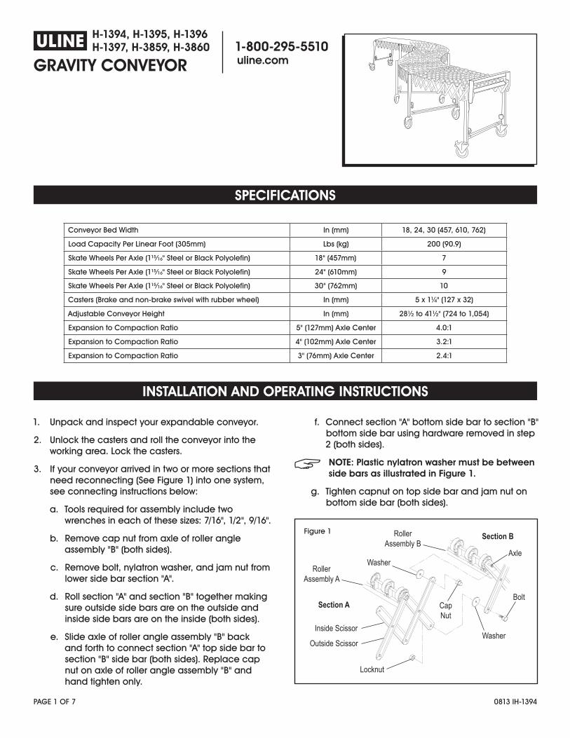
3. If your conveyor arrived in two or more sections that need reconnecting (See Figure 1) into one system, see connecting instructions below:
a. Tools required for assembly include two wrenches in each of these sizes: 7/16", 1/2", 9/16".
b. Remove cap nut from axle of roller angle assembly "B" (both sides).
c. Remove bolt, nylatron washer, and jam nut from lower side bar section "A".
d. Roll section "A" and section "B" together making sure outside side bars are on the outside and inside side bars are on the inside (both sides).
e. Slide axle of roller angle assembly "B" back and forth to connect section "A" top side bar to section "B" side bar (both sides). Replace cap nut on axle of roller angle assembly "B" and hand tighten only.
f. Connect section "A" bottom side bar to section "B" bottom side bar using hardware removed in step 2 (both sides).
NOTE: Plastic nylatron washer must be between side bars as illustrated in Figure 1.
g. Tighten capnut on top side bar and jam nut on bottom side bar (both sides).
RollerAssembly A
Section A
Section B
Washer
Bolt
Axle
CapNut
Inside Scissor
Locknut
RollerAssembly B
Outside ScissorWasher
SPECIFICATIONS
INSTALLATION AND OPERATING INSTRUCTIONS
Conveyor Bed Width In (mm) 18, 24, 30 (457, 610, 762)
Load Capacity Per Linear Foot (305mm) Lbs (kg) 200 (90.9)
Skate Wheels Per Axle (1⁄" Steel or Black Polyolefin) 18" (457mm) 7
Skate Wheels Per Axle (1⁄" Steel or Black Polyolefin) 24" (610mm) 9
Skate Wheels Per Axle (1⁄" Steel or Black Polyolefin) 30" (762mm) 10
Casters (Brake and non-brake swivel with rubber wheel) In (mm) 5 x 1⁄" (127 x 32)
Adjustable Conveyor Height In (mm) 28⁄ to 41⁄" (724 to 1,054)
Expansion to Compaction Ratio 5" (127mm) Axle Center 4.0:1
Expansion to Compaction Ratio 4" (102mm) Axle Center 3.2:1
Expansion to Compaction Ratio 3" (76mm) Axle Center 2.4:1
Figure 1
PAGE 2 OF 7 0813 IH-1394
INSTALLATION AND OPERATING INSTRUCTIONS CONTINUED
SAFETY
MAINTENANCE SCHEDULE
4. The legs are adjustable from 28⁄" to 41⁄" (724mm to 1,054mm). The leg elevation is factory set at 28⁄" (724mm). For proper gravity flow, a 5/16" (8mm) decline per expanded foot (305mm) is recommended. This may vary with carton weight or your specific applications.
5. To expand the conveyor:
a. Unlock the casters.
b. Grasp the handles on each side at both ends of the conveyor and pull until the conveyor is properly expanded.
c. Lock casters and begin use.
6. To set leg elevation for your application:
a. With the conveyor expanded, unscrew the adjustment knobs on the first leg set on the infeed end and lift up on the conveyor to height needed. Tighten adjustment knobs.
b. Do the same on the last leg set on the discharge end.
c. Adjust all legs in between to obtain proper gravity flow.
d. Close conveyor and check for slopes and valleys between the legs and readjust if needed.
CAUTION! Move conveyor only by grasping the handles located on each side at both ends of the conveyor.
CAUTION! When expanding or compacting your conveyor; keep hands, clothing and other items clear of the side bars.
WARNING! Do not exceed the conveyor load capacity, as it may result in possible operator injury or conveyor damage.
CAUTION! Avoid wearing excessively loose clothing when working with moving equipment.
CAUTION! Keep long hair pulled up to prevent it from becoming caught in moving parts.
NOTE: Broken or worn parts must be immediately replaced.
NOTE: Conveyors must only be serviced by properly trained and qualified technicians.
Your conveyor is designed to be virtually maintenance free. We do recommend that you regularly inspect the unit to ensure proper operation of mechanical and safety systems.
DAILY:
• Keep your conveyor free of dirt, debris and grease accumulation.
• Inspect leg elevations and adjust, as necessary, to ensure smooth product flow.
• Look for mechanical damage or worn components and replace as necessary.
MONTHLY:
• Check to ensure that all bolts and nuts are moderately tight.
Caution: Do not over torque as this may cause frame distortion and prevent the system from properly flexing.
Required tools to maintain your conveyor include: Two each of these size wrenches: 7/16", 1/2" and 9/16".
PAGE 3 OF 7 0813 IH-1394
OPERATING ISSUE POSSIBLE CAUSE RECOMMENDATIONS
Conveyor does not open or roll smoothly. Casters are locked or clogged with debris.
Bolts and nuts have been over tightened.
Conveyor has suffered physical damage.
Check casters and unlock or clear as necessary.
Check bolt tension.
Check unit and replace damaged parts.
Product stops on conveyor or does not flow smoothly.
Leg elevations are out of height adjustment.
Skate wheels are jammed.
Conveyor has suffered physical damage.
Readjust legs. (See Page 2, Step 6.)
Check and clear debris as necessary.
Check unit and replace damaged parts.
Uline will replace, free of charge, parts that are damaged during the course of normal operation due to material or workmanship defects.
This warranty extends for a period of two years on all mechanical components and one year on all electrical components (measured from the date you took possession of your conveyor).
NOTE: This warranty does not cover damage due to accident, misuse, abuse and negligence. This warranty does not cover damage due to improper operation or maintenance, connection to improper voltage supply, or attempted repair/modification by anyone other than authorized service personnel.
For specific warranty information or assistance, please contact ULINE at 1-800-295-5510.
WARRANTY
TROUBLESHOOTING
PRODUCT OPTIONS
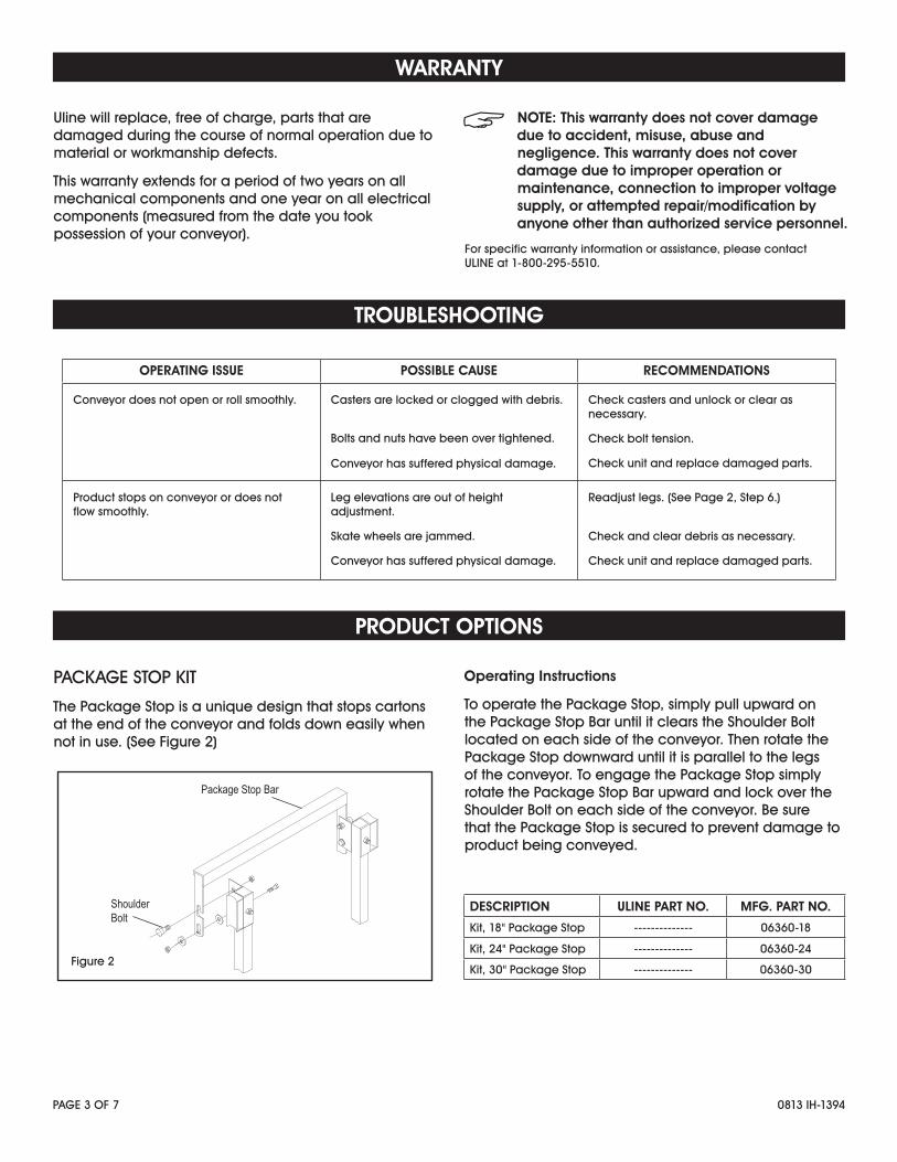
PACKAGE STOP KIT
The Package Stop is a unique design that stops cartons at the end of the conveyor and folds down easily when not in use. (See Figure 2)
Operating Instructions
To operate the Package Stop, simply pull upward on the Package Stop Bar until it clears the Shoulder Bolt located on each side of the conveyor. Then rotate the Package Stop downward until it is parallel to the legs of the conveyor. To engage the Package Stop simply rotate the Package Stop Bar upward and lock over the Shoulder Bolt on each side of the conveyor. Be sure that the Package Stop is secured to prevent damage to product being conveyed.
Package Stop Bar
ShoulderBolt
Figure 2
DESCRIPTION ULINE PART NO. MFG. PART NO.
Kit, 18" Package Stop -------------- 06360-18
Kit, 24" Package Stop -------------- 06360-24
Kit, 30" Package Stop -------------- 06360-30
PAGE 4 OF 7 0813 IH-1394
PRODUCT OPTIONS CONTINUED
6" SWIVEL CASTER
The 6" Swivel Casters provide easier rolling over uneven surfaces. 6 x 2" (152mm x 51mm) casters add 1⁄" (38mm) to conveyor height. (See Figure 3)
AXLE CONNECT HOOKS
Axle Connect Hooks link two or more conveyors together to serve as one continuous conveying surface. (See Figure 4)
Operating Instructions
Axle Connect Hooks link two or more conveyors. Simply push the conveyors together and engage the Axle Connect Hooks located on the last or end axle of the conveyor onto the first or end axle of the mating conveyor.
NOTE: Two Axle Connect Hooks are required.
IMPACT SUPPORT SECTION
The Impact Support Section is a built-in support on the infeed end of the conveyor where packages are loaded onto the conveyor. (See Figure 5)
NOTE: The Impact Support Section can be built in any length required for custom applications.
LEG CONNECT HOOKS
Leg Connect Hooks link two or more conveyors together to serve as one continuous conveying surface. (See Figure 6)
Operating Instructions
Leg Connect Hooks link two or more conveyors. Push the conveyors together and engage the Leg Connect Hooks located on each side of the conveyor legs onto the Leg Connect Bolts located on each side of the mating conveyor.
Axle Connect Hook
Figure 4
Leg ConnectBolt
Leg ConnectHook
Conveyor Leg
Figure 6
Caster 6 x 2Brake
Caster 6 x 2Non-BrakeFigure 3
Impact RollerAngle (Fig.B)
Impact RollerAngle Section
Standard RollerAngle (Fig. A)
A
B
Figure 5
DESCRIPTION ULINE PART NO. MFG. PART NO.
Axle Connect Hooks -------------- 60277
DESCRIPTION ULINE PART NO. MFG. PART NO.
Kit, Leg Connect Hooks, 5" Axle Centers
-------------- 06301-4
Kit, Leg Connect Hooks, 4" Axle Centers
-------------- 06301-3
Kit, Leg Connect Hooks, 3" Axle Centers
-------------- 06301-2
PAGE 5 OF 7 0813 IH-1394
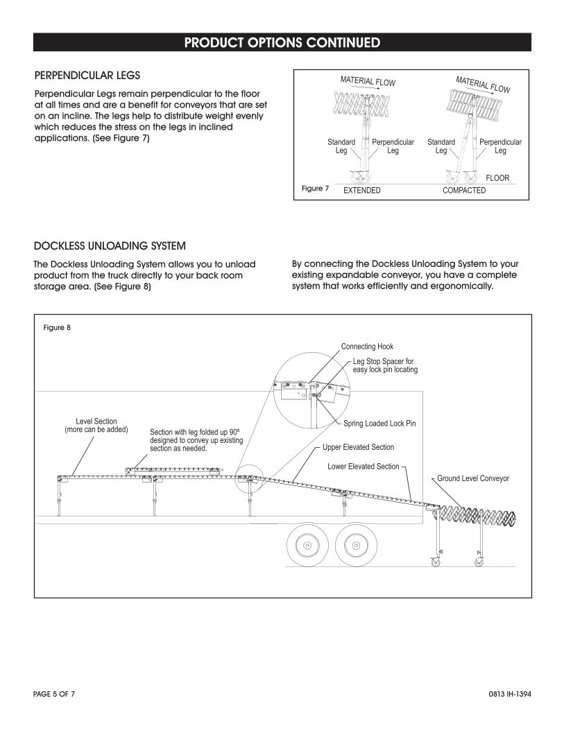
PERPENDICULAR LEGS
Perpendicular Legs remain perpendicular to the floor at all times and are a benefit for conveyors that are set on an incline. The legs help to distribute weight evenly which reduces the stress on the legs in inclined applications. (See Figure 7)
PRODUCT OPTIONS CONTINUED
Level Section(more can be added)
Connecting Hook
Leg Stop Spacer for easy lock pin locating
Spring Loaded Lock Pin
Upper Elevated Section
Lower Elevated SectionGround Level Conveyor
Section with leg folded up 90º designed to convey up existingsection as needed.
StandardLeg
MATERIAL FLOW MATERIAL FLOW
FLOOREXTENDED COMPACTED
PerpendicularLeg
StandardLeg
PerpendicularLeg
Figure 7
Figure 8
DOCKLESS UNLOADING SYSTEM
The Dockless Unloading System allows you to unload product from the truck directly to your back room storage area. (See Figure 8)
By connecting the Dockless Unloading System to your existing expandable conveyor, you have a complete system that works efficiently and ergonomically.
PAGE 6 OF 7 0813 IH-1394
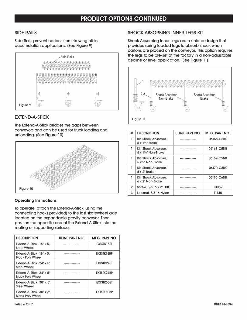
SIDE RAILS
Side Rails prevent cartons from skewing off in accumulation applications. (See Figure 9)
EXTEND-A-STICK
The Extend-A-Stick bridges the gaps between conveyors and can be used for truck loading and unloading. (See Figure 10)
Operating Instructions
To operate, attach the Extend-A-Stick (using the connecting hooks provided) to the last skatewheel axle located on the expandable gravity conveyor. Then position the opposite end of the Extend-A-Stick into the mating or supporting surface.
SHOCK ABSORBING INNER LEGS KIT
Shock Absorbing Inner Legs are a unique design that provides spring loaded legs to absorb shock when cartons are placed on the conveyor. This option requires the legs to be pre-set at the factory in a non-adjustable decline or level application. (See Figure 11)
PRODUCT OPTIONS CONTINUED
Side Rails
Figure 9
Shock AbsorberNon-Brake
2,3
1
Shock AbsorberBrake
Figure 11
Figure 10
# DESCRIPTION ULINE PART NO. MFG. PART NO.
1 Kit, Shock Absorber, 5 x 1⁄" Brake
-------------- 06168-C5BK
1 Kit, Shock Absorber, 5 x 1⁄" Non-Brake
-------------- 06168-C5NB
1 Kit, Shock Absorber, 5 x 2" Non-Brake
-------------- 06169-C5NB
1 Kit, Shock Absorber, 6 x 2" Brake
-------------- 06170-C6BK
1 Kit, Shock Absorber, 6 x 2" Non-Brake
-------------- 06170-C6NB
2 Screw, 3/8-16 x 2" HHC -------------- 10052
3 Locknut, 3/8-16 Nylon -------------- 11140
DESCRIPTION ULINE PART NO. MFG. PART NO.
Extend-A-Stick, 18" x 5', Steel Wheel
-------------- EXTSTK18ST
Extend-A-Stick, 18" x 5', Black Poly Wheel
-------------- EXTSTK18BP
Extend-A-Stick, 24" x 5', Steel Wheel
-------------- EXTSTK24ST
Extend-A-Stick, 24" x 5', Black Poly Wheel
-------------- EXTSTK24BP
Extend-A-Stick, 30" x 5', Steel Wheel
-------------- EXTSTK30ST
Extend-A-Stick, 30" x 5', Black Poly Wheel
-------------- EXTSTK30BP
PAGE 7 OF 7 0813 IH-1394
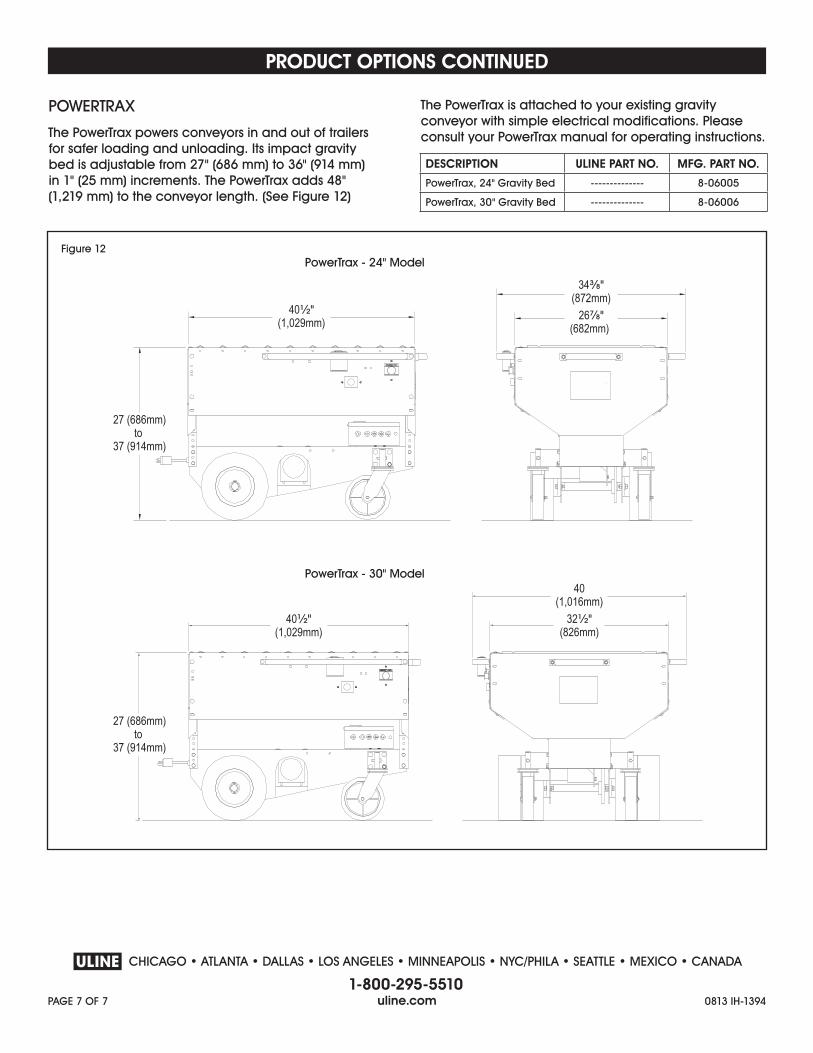
POWERTRAX
The PowerTrax powers conveyors in and out of trailers for safer loading and unloading. Its impact gravity bed is adjustable from 27" (686 mm) to 36" (914 mm) in 1" (25 mm) increments. The PowerTrax adds 48" (1,219 mm) to the conveyor length. (See Figure 12)
The PowerTrax is attached to your existing gravity conveyor with simple electrical modifications. Please consult your PowerTrax manual for operating instructions.