April 19, 2014 Attn: Tim Akerman Executive Director The Mancala Group PO Box 240 Launceston TAS 7250 Dear Tim, RE: GEOTECHNICAL INPUT TO CIEMAS STUDY 1 Background Information The Mancala Group (Mancala) has engaged Ground Control Engineering Pty Ltd (GCE) to provide geotechnical input to the preliminary scoping study for Ciemas deposit. The agreed scope of works is as follows: • Determine the major structural elements, domain lithologically and/or by structure type and present as stereo nets and description; • Describe structures and comment on their likely stability; • Provide comments on dig ability vs depth based on the available information; • Recommend procedures/practices for the collection of additional geotechnical data (additional 30 holes planned) Data provided by Mancala included geotechnical and geological data collected from 15 exploration drillholes, a Geology and Geomechanic Report of Ciemas Gold Project 1 and dtm’s of conceptual pit shells and mineralised lenses. 2 Structural Set Analysis Defect orientation data in the form of alpha and beta angles from the 15 exploration drillholes was compiled and analysed using the stereographic projection software DIPS. A total of 655 structural measurements were recorded in the drillhole logging and included in the analysis. Structural information included in the geotechnical logs included the following structure types: • FV • SHR • VL • VN The VL and VN defect types were combined for the purpose of the structural analysis. 1 Darmwan, A, I, 2012. Geology and Geomechanic Report of Ciemas Gold Project, Area Mining Mineral Au Development in Pasir Manggu, Sekolah, Cikuda and Cibatu Prospect Area, Ciemas District, Sukabumi Regency, West Java Province, Pt. Wilton Wahana Indonesia, 22 July 2012 G0036.AA_RE01_V02 1
Transcript
April 19, 2014
Attn: Tim Akerman Executive Director The Mancala Group PO Box 240 Launceston TAS 7250
Dear Tim,
RE: GEOTECHNICAL INPUT TO CIEMAS STUDY
1 Background Information
The Mancala Group (Mancala) has engaged Ground Control Engineering Pty Ltd (GCE) to provide geotechnical input to the preliminary scoping study for Ciemas deposit. The agreed scope of works is as follows:
• Determine the major structural elements, domain lithologically and/or by structure type and present as stereo nets and description;
• Describe structures and comment on their likely stability; • Provide comments on dig ability vs depth based on the available information; • Recommend procedures/practices for the collection of additional geotechnical data (additional
30 holes planned) Data provided by Mancala included geotechnical and geological data collected from 15 exploration drillholes, a Geology and Geomechanic Report of Ciemas Gold Project1 and dtm’s of conceptual pit shells and mineralised lenses.
2 Structural Set Analysis
Defect orientation data in the form of alpha and beta angles from the 15 exploration drillholes was compiled and analysed using the stereographic projection software DIPS. A total of 655 structural measurements were recorded in the drillhole logging and included in the analysis. Structural information included in the geotechnical logs included the following structure types:
• FV • SHR • VL • VN
The VL and VN defect types were combined for the purpose of the structural analysis.
1 Darmwan, A, I, 2012. Geology and Geomechanic Report of Ciemas Gold Project, Area Mining Mineral Au Development in Pasir Manggu, Sekolah, Cikuda and Cibatu Prospect Area, Ciemas District, Sukabumi Regency, West Java Province, Pt. Wilton Wahana Indonesia, 22 July 2012
G0036.AA_RE01_V02 1
The structure data was separated into the following major lithologies (rock units):
• VBR • TUFF • LPS
The structural data was analysed separately for each lithology and structure type included in the data set. The Terzaghi correction was applied to structure contour plots to account for drilling bias. The stereonets used in the structural analysis are included in Appendix A. The stereonets in Appendix A were used to identify the major structural elements and define structural sets as outlined in Table 1.
Table 1 Major Structural Set Orientations
Structural sets for the different defect types, with similar mean orientations, have been assigned the same structural set number across the three major lithologies as shown in Table 1.
3 Discussion of Potential Structural Influence on Proposed Pits
GCE has completed an initial review of the potential impact of the major structural sets outlined in Table 1 with respect to the preliminary pit design shells provided by Mancala. The pit design shell outlines are shown in yellow in Figure 1 below. Figure 1 Conceptual Pit Design Shell Outlines – Plan View
As shown in Figure 1, the proposed pits are generally orientated along a NE/SW strike, with the major walls oriented NE/SW and dipping to the SE and NW on either side of the pits. The end walls are generally NW/SE striking and dip to the NE and SW at either end of the pits. The potential impact of the major structural sets outlined in Table 1 with respect to the preliminary pit design shells shown in Figure 1 is summarized as follows: Structural Set 1: Structural Set 1 is a dominant structural orientation in the data set and consists of steep south to south-south west dipping structures. Set 1 is evident in all structure types across the three major rock types in the data set. This set has the potential to contribute to topple style failure on the southern walls of the proposed pits. The likelihood and potential for topple failure requires further detailed assessment and depends on the pit wall angles, the spacing and persistence of structural discontinuities (block size) and the shear strength properties of the Set 1 defects. Set 1 is unlikely to be associated with discrete planar wedge failure on this structural set alone due to it being relatively steeply dipping and unlikely to daylight in the pit walls. It may however, provide a bounding release structure for potential wedge failure on the eastern pit walls, associated with Structural Set 3. Structural Set 2: Structural Set 2 is a similarly dominant structural orientation in the data set and consists of steep north to north-north west dipping structures. Set 2 is evident in all structure types across the three major rock types in the data set. This set has the potential to contribute to topple style failure on the northern walls of the proposed pits. As with Set 1, the likelihood and potential for topple failure requires further detailed assessment and depends on the pit wall angles, the spacing and persistence of structural discontinuities (block size) and the shear strength properties of the Set 2 defects. As with Set 1, Set 2 is unlikely to be associated with discrete planar wedge failure on this structural set alone due to it being relatively steeply dipping and unlikely to daylight in the pit walls. It may however, provide a bounding release structure for potential wedge failure on the eastern pit walls, associated with Structural Set 3. Structural Set 3: Structural Set 3 consists of relatively flat, westerly dipping structures. Set 3 is a less dominant structural orientation and is only evident in the SHR and VL/VN structures in the VBR rock unit and in the VL/VN structures in the LPS rock unit. Set 3 has the potential to contribute to planar and wedge style failure on the eastern walls of the proposed pits. The overall potential for wedge failure is limited by the flat dip of the Set 3 structures which ranges from approximately 15° to 35°. If wedge failure is to occur, the friction angle of the defect(s) must be less than the dip of the sliding plane. GCE understand that no test data regarding defect shear strength properties is available at this stage however, friction angles of less than 30° are typically associated with the presence of soft infill materials on the defect surfaces. The potential for wedge failure is somewhat increased by the presence of structural sets 1 and 2 which may form bounding release planes if they are found to intersect Set 3 structure in the pit walls.
4 Rock Strength and Excavatability Point load tests (Is50) and Unconfined Compressive Strength (UCS) tests were undertaken on a number of samples from the study area and reported in the Wilton (2012) report. The Is50 values in Table 2 range from medium strong to the lower range of very strong. The point load tests overestimate the intact rock strength obtained from the UCS test in five of the samples tested. The test results do not have the failure mode recorded so it is unknown if any of the samples failed on pre-existing structures. UCS values range from medium strong to strong (31.3 MPa to 68.2 MPa). Mancala has informed GCE that the block sample was recovered from an inclined shaft developed in 2012. The incline shaft was developed in Volcanic Breccia (VBR). Photographs taken inside the shaft show fresh, blocky ground conditions. There is
G0036.AA_RE01_V02 3
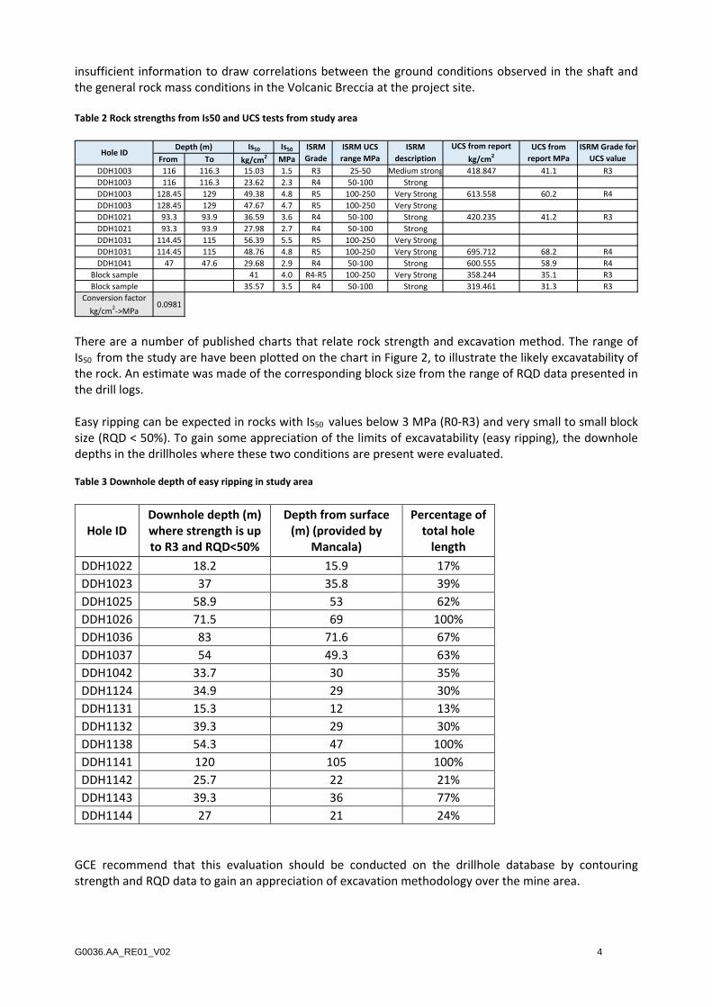
insufficient information to draw correlations between the ground conditions observed in the shaft and the general rock mass conditions in the Volcanic Breccia at the project site. Table 2 Rock strengths from Is50 and UCS tests from study area
There are a number of published charts that relate rock strength and excavation method. The range of Is50 from the study are have been plotted on the chart in Figure 2, to illustrate the likely excavatability of the rock. An estimate was made of the corresponding block size from the range of RQD data presented in the drill logs. Easy ripping can be expected in rocks with Is50 values below 3 MPa (R0-R3) and very small to small block size (RQD < 50%). To gain some appreciation of the limits of excavatability (easy ripping), the downhole depths in the drillholes where these two conditions are present were evaluated. Table 3 Downhole depth of easy ripping in study area
Hole ID Downhole depth (m) where strength is up to R3 and RQD<50%
GCE recommend that this evaluation should be conducted on the drillhole database by contouring strength and RQD data to gain an appreciation of excavation methodology over the mine area.
Additional geotechnical data collection is required in order to complete a detailed geotechnical assessment for the proposed Ciemas deposit mine. The geotechnical data collection should include specific, targeted geotechnical drilling, logging and laboratory geotechnical testing. The following recommendations are provided by GCE regarding geotechnical data collection:
5.1 Geotechnical Drilling
• The geotechnical drilling program should be designed to provide adequate coverage of the proposed mine area, while optimizing drilling metres and relevant data collection. The drilling program must capture adequate geotechnical information to characterize the main geotechnical domains that will comprise the pit walls. Key data includes rockmass characterization, structural data and rock strength parameters;
• Drill holes should be minimum HQ3 (triple tube diamond), drilled with water or a suitable mud mix. Air coring is totally unsuitable;
• The drill should be a heavy duty rig, capable of easily achieving the required depth. Top head drives are preferred to kelly drives to keep the drive pressure constant and vibration to a minimum;
• A variety of soft and hard materials are likely to be encountered and may present some problems with core recovery and quality. The drilling contractor should have a variety of drill bits on hand for trials to achieve the best quality of core recovered, including diamond-impregnated and stepped-face bits;
• Core recovery and core quality is the priority of the geotechnical drilling program;
• Reliable and quality controlled core orientation is required;
• It is recommended that geotechnical logging be conducted at the rig and in the splits.
5.2 Geotechnical Logging
• Detailed geotechnical core logging must be completed by an experienced geotechnical logger in order to collect the data required for geotechnical characterisation and analyses. This data will provide the key input for subsequent assessment of pit slope design parameters. The geotechnical logging should provide standardised geotechnical core logs for each cored geotechnical hole. Key parameters include core photography, RQD, strength estimates, weathering and fracture/defect characterisation. If required, GCE can assist with the development of appropriate geotechnical logging templates for the project.
• The geotechnical logging should be periodically reviewed by an experienced geotechnical engineer to ensure the required and quality and consistency of logging is achieved.
5.3 Laboratory Geotechnical Testing
• Selection and collection of samples for laboratory testing should be conducted in parallel with geotechnical core logging. Samples must be selected to target the specific needs of the geotechnical characterisation studies (ie. rock and defect strength characteristics), and follow current best practice for standardised geotechnical core sampling and testing.
• The anticipated laboratory testing requirements may include the following tests;
o Unconfined Compressive Strength (UCS) testing
o Direct Shear tests for determination of shear strength of discontinuities
G0036.AA_RE01_V02 6
o Triaxial tests to estimate rock mass shear strength
o Slake durability for waste rock characterisation purposes
o Density
o Moisture Content
o Atterburg Limits (for applicable soil samples)
Note: The actual testing requirements will depend on the range of ground conditions and lithologies encountered and should be reviewed throughout the drilling program, in consultation with an experienced geotechnical engineer.
• The services of a NATA accredited laboratory will need to be secured for all geotechnical testing and testing must be conducted according to applicable Australian and international testing standards.
6 Closure We trust that this letter report meets your requirements. Should you require further clarification, please do not hesitate to contact the undersigned.
Yours sincerely,
GROUND CONTROL ENGINEERING PTY LTD
Delia Sidea Principal Geotechnical Engineer M 0429 206 550