Sinusoid Steady-State Analysis Objectives: 1) Be able to perform a phasor transform and its inverse; 2) Be able to phasor-transform a circuit; 3) Solve arbitrarily complex circuits with sinusoidal sources using phasor method.
Transcript
Sinusoid Steady-State AnalysisObjectives:
1) Be able to perform a phasor transform
and its inverse;
2) Be able to phasor-transform a circuit;
3) Solve arbitrarily complex circuits with
sinusoidal sources using phasor
method.
Sinusoid Steady-State AnalysisReview the terminology of sinusoids
v(t) = Vmcos(t + ) V
•Vm : Amplitude or magnitude
• : angular frequency [rad/s]
•t : time [s]
• : phase angle [deg]
•f = /2 : frequency [Hz]
•T = 1/f : period [s]
What is the frequency of the sinusoid
given below?
A. 4t
B. 4 Hz
C. 4 rad/s
i(t) = 36 cos(4t + 45) mA
What is the phase angle of the
sinusoid given below?
A. 60 deg
B. 60 rad
C. 60 deg
v(t) = 50 cos(3000t 60) V
Suppose we want to find the value of the
sinusoidal current described below at
t = 5 ms. When we substitute this value
for t into the sinusoid, the argument for
the cosine function has what units?
A. degrees
B. radians
C. A mix of degrees
and radians
i(t) = 0.2 cos(50t + 45) A
Sinusoid Steady-State AnalysisEvaluating a sinusoid at a specified time
i(0.005) = 0.2 cos(50t + 45) A50 has the units rad/s
50t has the units radians
45 has the units degrees
Need to convert 50t to degrees, or 45 to
radians, and set your calculator
appropriately!
2/360 = 50(0.005)/x x = 45
Thus, i(0.005) = 0.2 cos(45 + 45) A
= 0.2 cos(90) = 0 A
Sinusoid Steady-State AnalysisSuppose v(t) = Vmcos(t + ) V in the circuit
below:
The equation for i(t) is )cos()()(
tVtRidt
tdiL m
The solution of this equation for i(t) is
)(tan
)cos()(
)cos()(
)(
1
22
)(
22
RL
tLR
Ve
LR
Vti mtLRm
where
Consider the equation for the current
in the RL circuit with the sinusoidal
source:
Which term(s) go to 0 as t ∞?
A. The first term
B. The second term
C. Both terms
D. Neither term
)cos()(
)cos()(
)(22
)(
22
t
LR
Ve
LR
Vti mtLRm
Sinusoid Steady-State Analysis
•The first term is the transient term – it
decays to 0 as t goes to infinity
•The second term is the steady-state term –
it persists for all time greater than 0. This
term
• Is sinusoidal
• Has the same frequency as the input voltage
• Has a different magnitude and phase angle
compared to the input voltage
)cos()(
)cos()(
)(22
)(
22
t
LR
Ve
LR
Vti mtLRm
Sinusoid Steady-State AnalysisThe circuit analysis techniques we are
studying will allow us to calculate the
sinusoidal steady-state response of the
circuit – that is, the circuit’s response
to a sinusoidal input once the transient
response has effectively decayed to 0.
This is also called the AC Steady-State
(ACSS) response.
Sinusoid Steady-State AnalysisPhasor
• A complex number in polar form, with a
magnitude and phase angle
• Derived from a sinusoid using the phasor
transform
jtj
m
jtj
m
tj
m
m
j
j
eeV
eeV
eV
tVtv
e
je
Re
Re
Re
Re
)(
)cos()(
cos
sincos
Now
:identitys Euler'
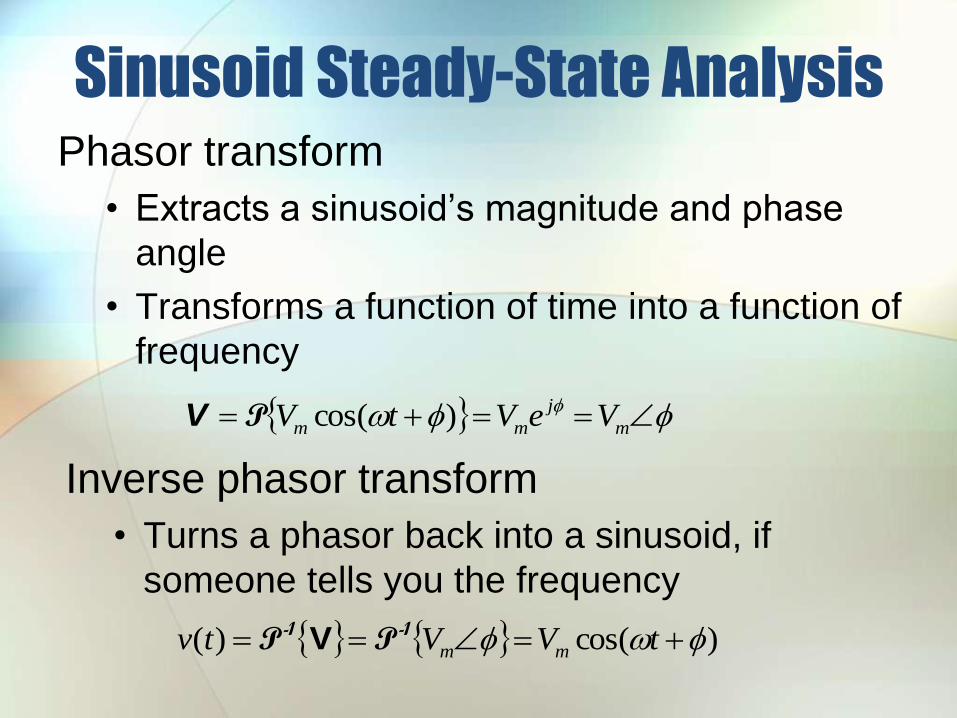
Sinusoid Steady-State AnalysisPhasor transform
• Extracts a sinusoid’s magnitude and phase
angle
• Transforms a function of time into a function of
frequency
m
j
mm VeVtV )cos(PV
Inverse phasor transform
• Turns a phasor back into a sinusoid, if
someone tells you the frequency
)cos()( tVVtv mm
-1-1 PP V
Suppose
i(t) = 36 cos(4t + 45) mA
Then the phasor transform of i(t) is
A. 36 mA
B. 3645 mA
C. 364t mA
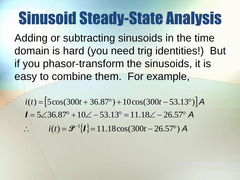
Sinusoid Steady-State AnalysisAdding or subtracting sinusoids in the time
domain is hard (you need trig identities!) But
if you phasor-transform the sinusoids, it is
easy to combine them. For example,
A
A
A
)57.26300cos(18.11)(
57.2618.1113.531087.365
)13.53300cos(10)87.36300cos(5)(
1
tti
ttti
I
I
P
Sinusoid Steady-State Analysis
Consider the equations that relate
voltage and current in a resistor,
inductor, and capacitor in the time
domain, and in the phasor domain.
Sinusoid Steady-State Analysis
Time domainPhasor (frequency)
domain
P
)cos()()(
)cos()(
tRItRitv
tIti
m
m
m
m
RIR
I
IV
I
Note that the voltage and current phasors for a resistor
have the same phase angle – therefore we say that the
voltage and current in a resistor are “in phase”.
Resistors:
Sinusoid Steady-State Analysis
Time domain
Phasor (frequency) domain
P
)90cos(
)sin(
)()(
)cos()(
tLI
tLI
dttdiLtv
tIti
m
m
m
I
V
I
LjeLIj
jeLI
eeLI
eLI
I
j
m
j
m
jj
m
j
m
m
)(
90
)90(
In an inductor, the voltage leads the current by 90
Inductors:
Sinusoid Steady-State Analysis
Time domain
Phasor (frequency) domain
P
)90cos(
)sin(
)()(
)cos()(
tCV
tCV
dttdvCti
tVtv
m
m
m
V
I
V
CjeCVj
jeCV
eeCV
eCV
V
j
m
j
m
jj
m
j
m
m
)(
90
)90(
In a capacitor, the voltage lags the current by 90
Capacitors:
The impedance of a resistor is
A. Always a real number
B. Always an imaginary number
C. A complex number with real
and imaginary parts
The impedance of an inductor is
A. A real number
B. A positive imaginary
number
C. A negative imaginary
number
The impedance of a capacitor has the
units
A. Farads [F]
B. Henries [H]
C. Ohms []
Impedance is a phasor.
A. True
B. False
Sinusoid Steady-State AnalysisSummary:
• In the time domain
• Resistor: v(t) = Ri(t)
• inductor: v(t) = Ldi(t)/dt
• Capacitor: i(t) = Cdv(t)/dt
• In the phasor domain V = ZI
• Z is impedance, defined as the ratio of V to I
• Z has the units Ohms []
• Resistor: ZR = R
• Inductor: ZL = jL
• Capacitor: ZC = 1/jC = -j/C
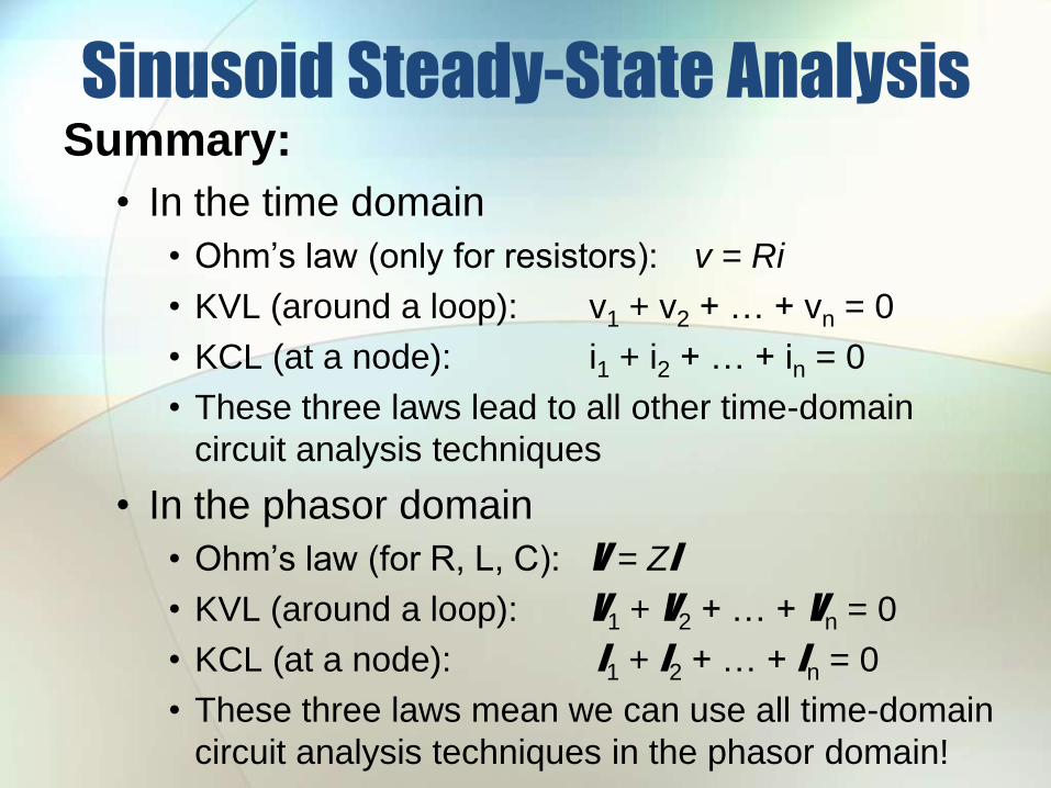
Sinusoid Steady-State AnalysisSummary:
• In the time domain
• Ohm’s law (only for resistors): v = Ri
• KVL (around a loop): v1 + v2 + … + vn = 0
• KCL (at a node): i1 + i2 + … + in = 0
• These three laws lead to all other time-domain
circuit analysis techniques
• In the phasor domain
• Ohm’s law (for R, L, C): V = ZI
• KVL (around a loop): V1 + V2 + … + Vn = 0
• KCL (at a node): I1 + I2 + … + In = 0
• These three laws mean we can use all time-domain
circuit analysis techniques in the phasor domain!
Sinusoid Steady-State Analysis
Circuit in the
time domain
Circuit in the
phasor domain
Solution in the
time domain
Solution in the
phasor domain
P
P -1
Easy –
algebra!
Hard –
calculus!
Sinusoid Steady-State AnalysisSteps in ACSS Analysis:
1. Redraw the circuit (the phasor transform does not
change the components or their connections).
2. Phasor transform all known v(t) and i(t).
3. Represent unknown voltages and currents with V
and I.
4. Replace component values with impedance (Z)
values.
5. Use any circuit analysis method(s) to write
equations and solve them with a calculator.
6. Inverse-transform the result, which is a phasor,
back to the time domain.
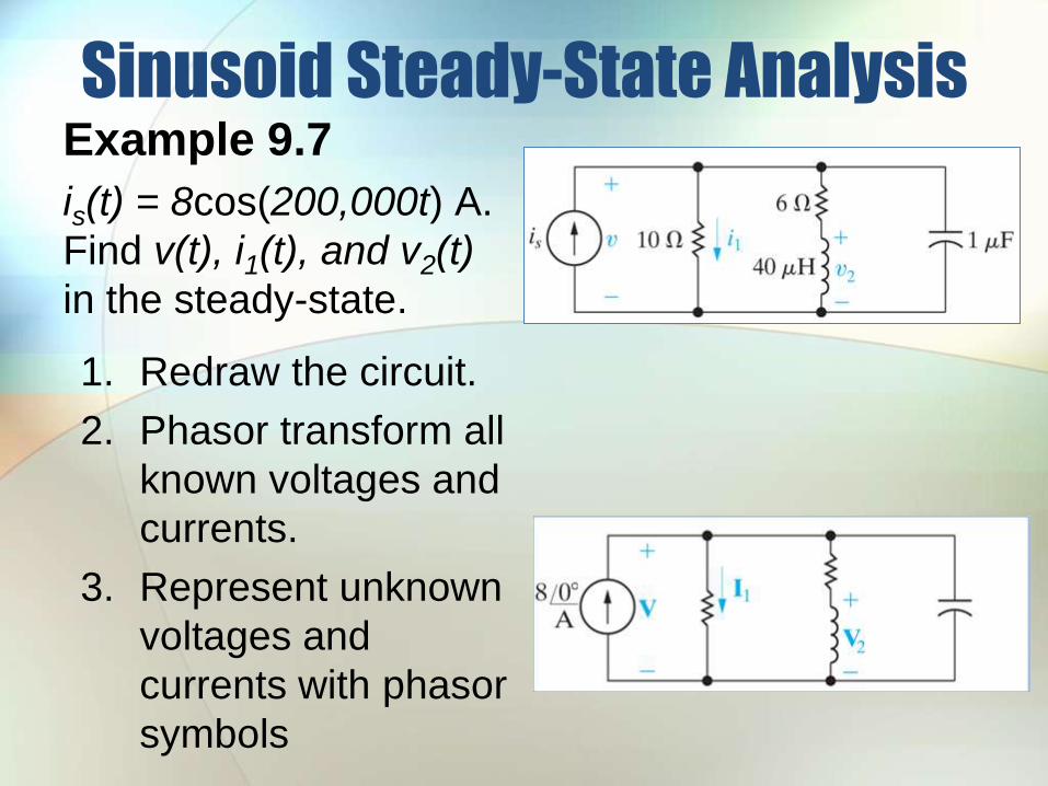
Sinusoid Steady-State AnalysisExample 9.7
is(t) = 8cos(200,000t) A.
Find v(t), i1(t), and v2(t)
in the steady-state.
1. Redraw the circuit.
2. Phasor transform all
known voltages and
currents.
3. Represent unknown
voltages and
currents with phasor
symbols
The next step is to calculate the
impedance of all resistors, inductors,
and capacitors. Actually, the
impedance of the resistors doesn’t
require calculation.
A. True
B. False
The impedance of inductors and
capacitors is calculated using
A. The source frequency
B. The component value
C. Both A and B
Sinusoid Steady-State AnalysisExample 9.7
is(t) = 8cos(200,000t) A.
Find v(t), i1(t), and v2(t)
in the steady-state.
4. Calculate the
impedances of all
resistors, inductors,
and capacitors.
5)1)(000,200(
8)40)(000,200(
jj
C
jZ
jjLjZ
C
L
Sinusoid Steady-State AnalysisExample 9.7
is(t) = 8cos(200,000t) A.
Find v(t), i1(t), and v2(t)
in the steady-state.
5. Use DC circuit analysis techniques to find the
phasor V.
• In this problem, we’ll simplify the circuit by replacing
all impedances by one equivalent impedance, and
use Ohm’s law for phasors.
V)2532()08)(34(
)34(5||)86(||10
jjZ
jjjZeq
IV
Sinusoid Steady-State AnalysisExample 9.7
is(t) = 8cos(200,000t) A.
Find v(t), i1(t), and v2(t)
in the steady-state.
6. Inverse phasor-transform the result to get back
to the time domain.
V
V V
)87.36000,200cos(4087.3640)(
87.3640)2432(
1
ttv
j
P
V
The most direct way to calculate the
phasor I1 is
A. Voltage division
B. Current division
C. Source transform
Sinusoid Steady-State AnalysisExample 9.7
is(t) = 8cos(200,000t) A.
Find v(t), i1(t), and v2(t)
in the steady-state.
5. Use DC circuit analysis techniques to find the
phasor I1.
• Use current division.
A )4.22.3(
)08(10
)34(
1
1
j
j
Z
Zs
eq
II
Sinusoid Steady-State AnalysisExample 9.7
is(t) = 8cos(200,000t) A.
Find v(t), i1(t), and v2(t)
in the steady-state.
6. Inverse phasor-transform the result to get back
to the time domain.
A
A A
)87.36000,200cos(487.364)(
87.364)4.22.3(
1
1
1
tti
j
P
I
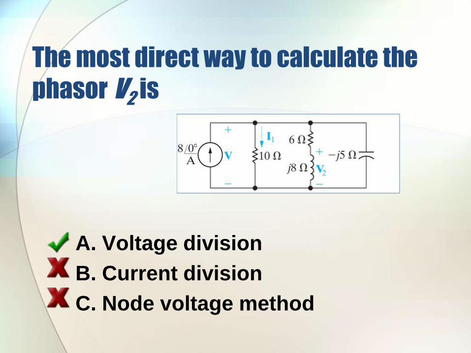
The most direct way to calculate the
phasor V2 is
A. Voltage division
B. Current division
C. Node voltage method
Sinusoid Steady-State AnalysisExample 9.7
is(t) = 8cos(200,000t) A.
Find v(t), i1(t), and v2(t)
in the steady-state.
5. Use DC circuit analysis techniques to find the
phasor V2.
• Use voltage division.
V )032(
)2432(86
82
j
jj
j
ZZ
Z
LR
L
VV
Sinusoid Steady-State AnalysisExample 9.7
is(t) = 8cos(200,000t) A.
Find v(t), i1(t), and v2(t)
in the steady-state.
6. Inverse phasor-transform the result to get back
to the time domain.
V
V V
ttv
j
000,200cos32032)(
032)032(
1
2
2
P
V
Sinusoid Steady-State AnalysisExample 9.7
Suppose we can vary the frequency of the current
source. What frequency will cause is(t) and v(t) to
be in-phase in the steady-state?
If is(t) and v(t) are in-phase in the
steady-state, this means
A. Their phase angles are the same.
B. The equivalent impedance seen by the
current source has a phase angle of 0.
C. The equivalent impedance seen by the
current source is purely resistive.
D. All of the above.
Sinusoid Steady-State Analysis
rad/s 000,50)40(
3614036
0)36(10100)36(10
)36(10101
)36(10
)36(10106036
)6)(6(10
)6)(6)((10
)6)(6(10
)6(10
)6)(6(10
)6)(6(
6
1
10
11
22
2
22
22
22
22
2222
L
CL
LCLL
LCL
Z
L
LCjLjL
LjLj
LjLjCj
LjLj
Lj
LjLj
LjLj
CjLjZ
eq
eq
Im
Sinusoid Steady-State AnalysisExample 9.7
Suppose we can vary the frequency of the current
source. What frequency will cause is(t) and v(t) to