26
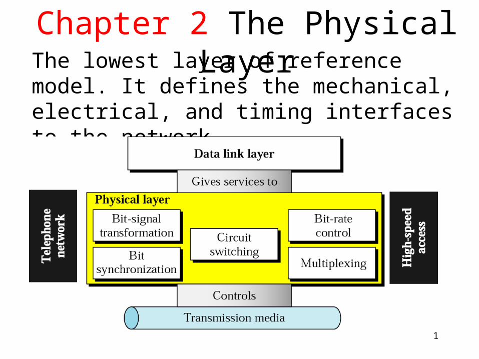
1 Chapter 2 The Physical Layer The lowest layer of reference model. It defines the mechanical, electrical, and timing interfaces to the network.
| Date post: | 21-Dec-2015 |
| Category: |
Documents |
| View: | 222 times |
| Download: | 1 times |
1
Chapter 2 The Physical LayerThe lowest layer of reference model. It defines the mechanical, electrical, and timing interfaces to the network.
2
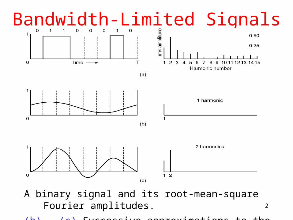
Bandwidth-Limited Signals
A binary signal and its root-mean-square Fourier amplitudes.
(b) – (c) Successive approximations to the original signal.
3
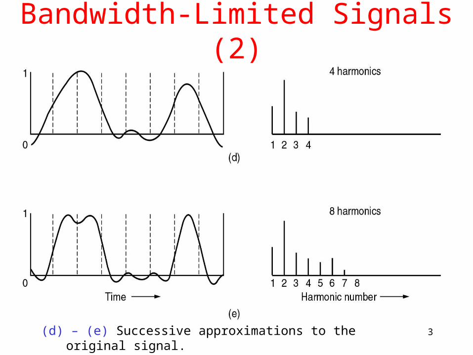
Bandwidth-Limited Signals (2)
(d) – (e) Successive approximations to the original signal.

4
BANDWIDTH AND INFORMATION CAPACITY
Bandwidth is the span of frequencies within the spectrum occupied by a signal and used by the signal for conveying information.
Carrying information requires bandwidth.
5
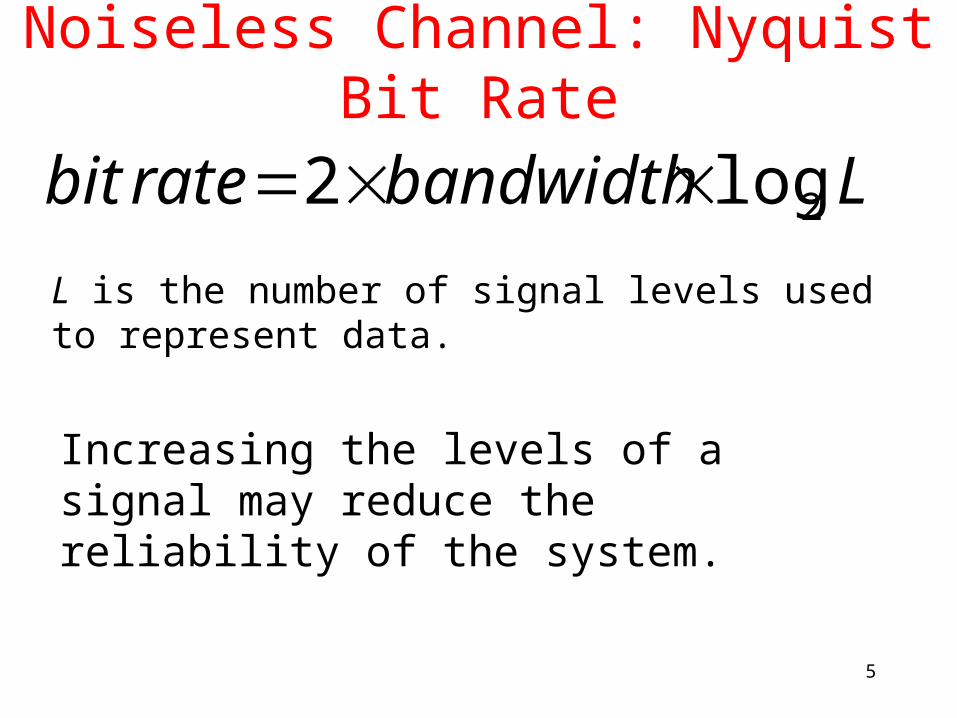
Noiseless Channel: Nyquist Bit Rate
Lbandwidthratebit 2log2 L is the number of signal levels used to represent data.
Increasing the levels of a signal may reduce the reliability of the system.
6
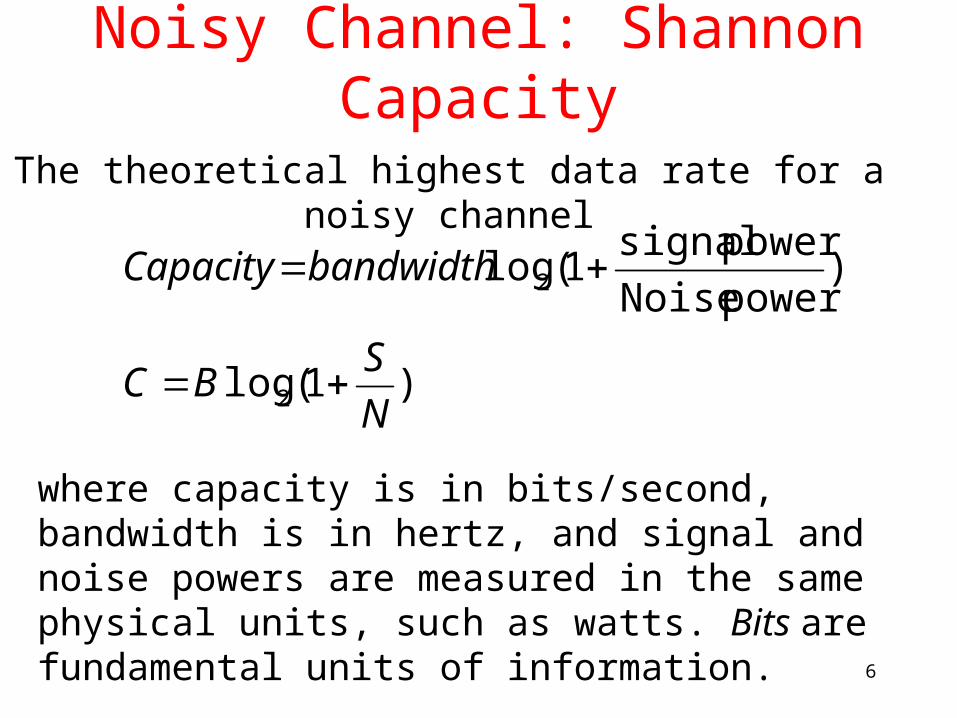
Noisy Channel: Shannon Capacity
where capacity is in bits/second, bandwidth is in hertz, and signal and noise powers are measured in the same physical units, such as watts. Bits are fundamental units of information.
The theoretical highest data rate for a noisy channel
)1(log
)power Noise
power signal1(log
2
2
N
SBC
bandwidthCapacity

7
Using both limits
The Shannon capacity gives us the upper limit;
the Nyquist formula tells us how many signal levels we need.
8
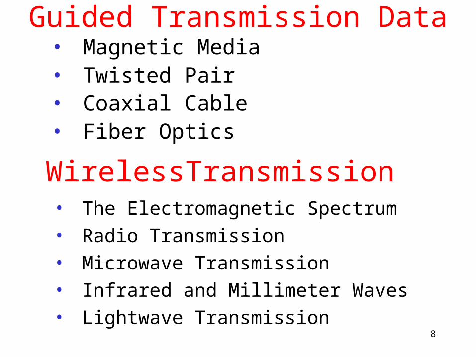
Guided Transmission Data• Magnetic Media• Twisted Pair• Coaxial Cable• Fiber Optics
WirelessTransmission• The Electromagnetic Spectrum
• Radio Transmission
• Microwave Transmission
• Infrared and Millimeter Waves
• Lightwave Transmission
9
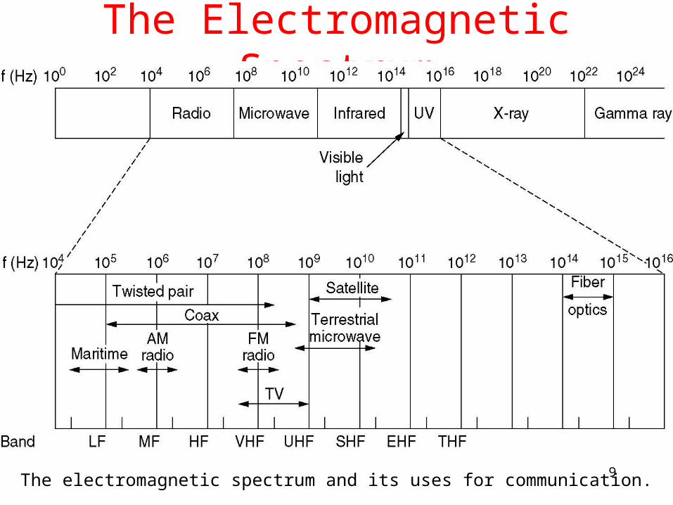
The Electromagnetic Spectrum
The electromagnetic spectrum and its uses for communication.
10
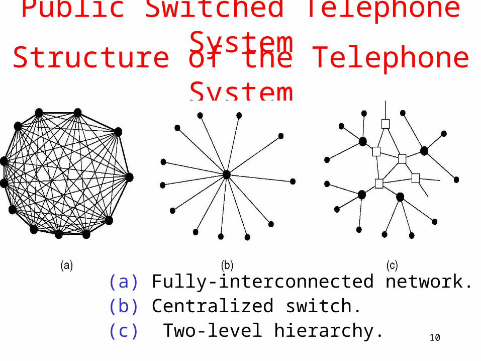
Structure of the Telephone System
(a) Fully-interconnected network.(b) Centralized switch.(c) Two-level hierarchy.
Public Switched Telephone System
11
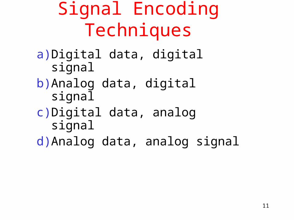
Signal Encoding Techniques
a) Digital data, digital signalb) Analog data, digital signalc) Digital data, analog signald) Analog data, analog signal
12
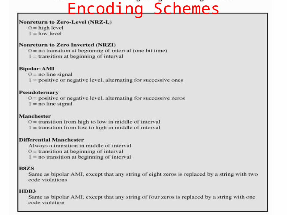
Encoding Schemes
13
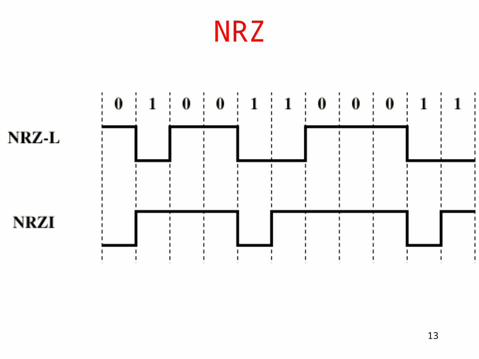
NRZ

14
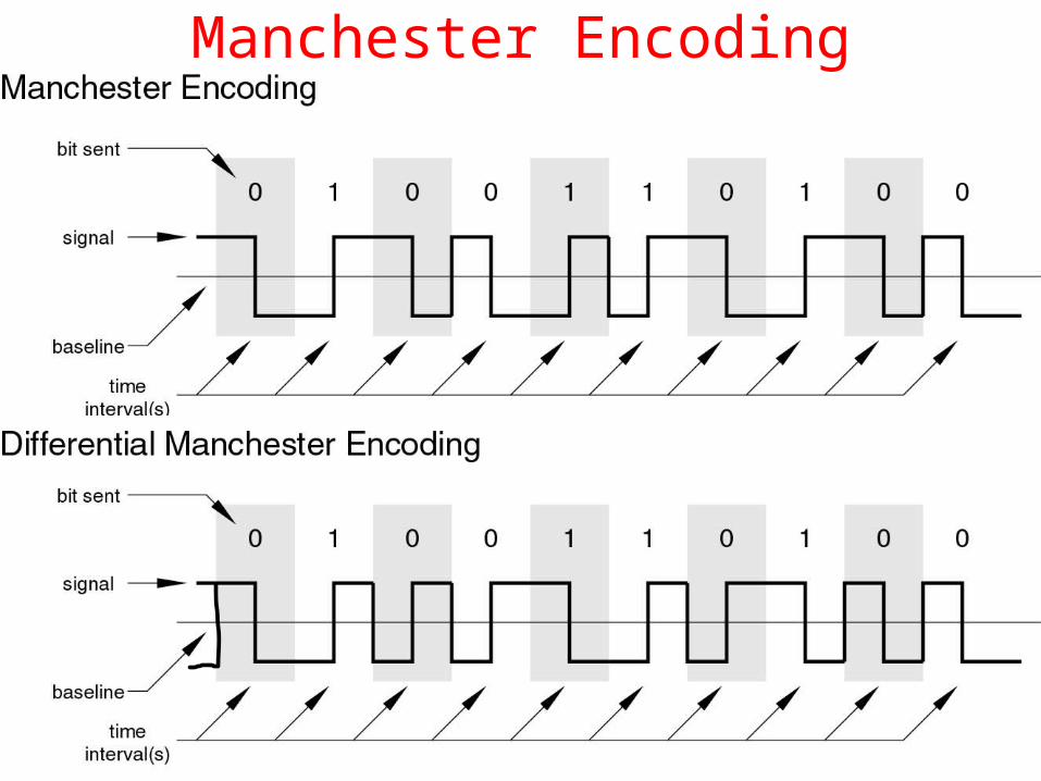
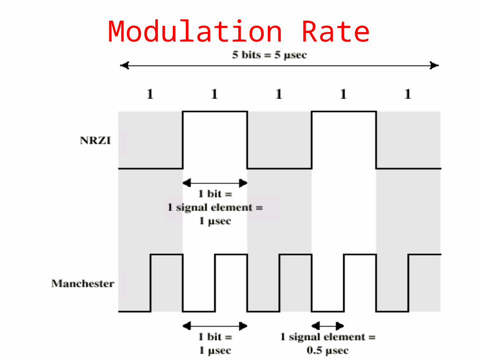
Biphasea) Manchester
– Transition in middle of each bit period– Transition serves as clock and data– Low to high represents one– High to low represents zero– Used by IEEE 802.3
b)Differential Manchester– Mid-bit transition is clocking only– Transition at start of a bit period represents zero– No transition at start of a bit period represents one– Note: this is a differential encoding scheme– Used by IEEE 802.5
15
Manchester Encoding
16
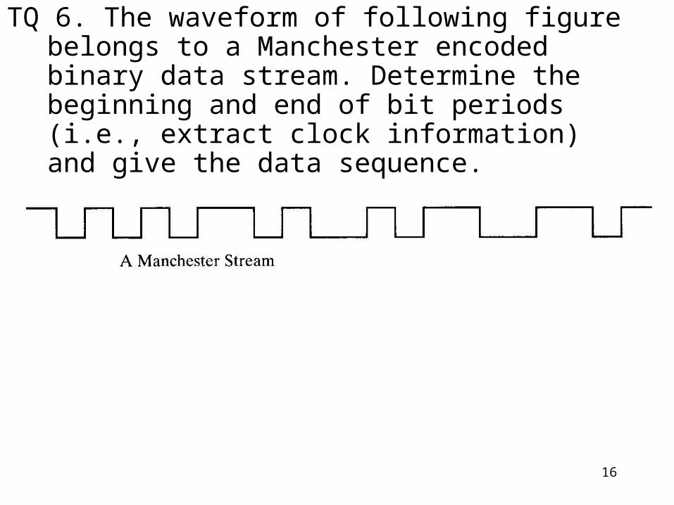
TQ 6. The waveform of following figure belongs to a Manchester encoded binary data stream. Determine the beginning and end of bit periods (i.e., extract clock information) and give the data sequence.
17
Modulation Rate

18
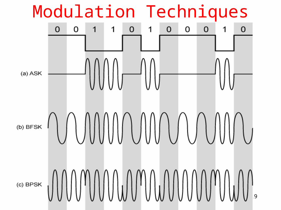
Digital Data, Analog Signal
a) Public telephone system– 300Hz to 3400Hz– Use modem (modulator-demodulator)
b) Amplitude shift keying (ASK)c) Frequency shift keying (FSK)d) Phase shift keying (PK)
19
Modulation Techniques
20
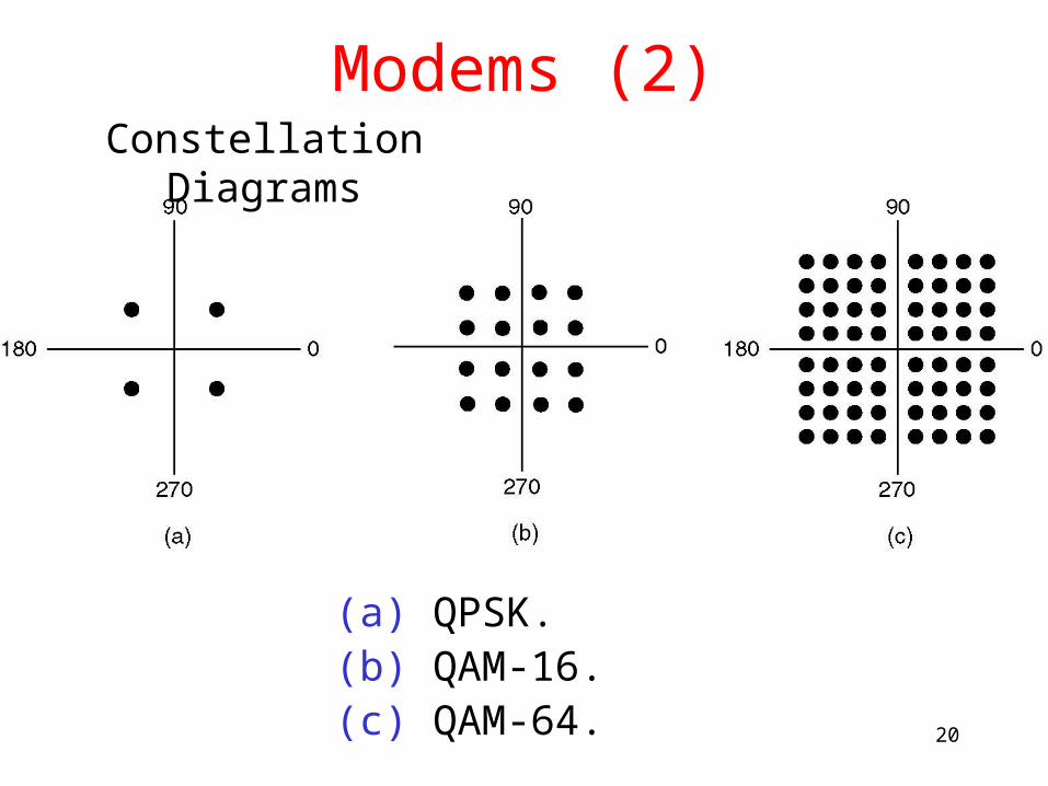
Modems (2)
(a) QPSK.(b) QAM-16.(c) QAM-64.
Constellation Diagrams
21
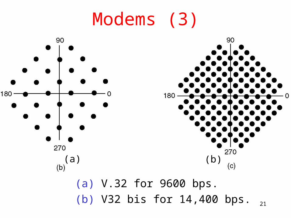
Modems (3)
(a) V.32 for 9600 bps.
(b) V32 bis for 14,400 bps.
(a) (b)
22
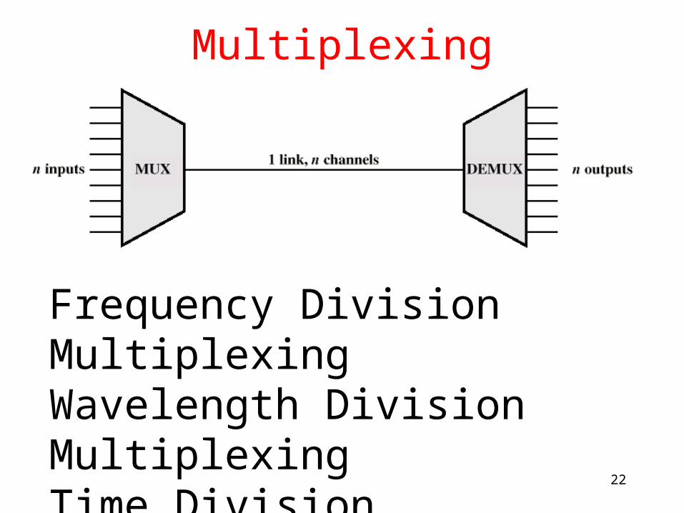
Multiplexing
Frequency Division MultiplexingWavelength Division MultiplexingTime Division Multiplexing
23
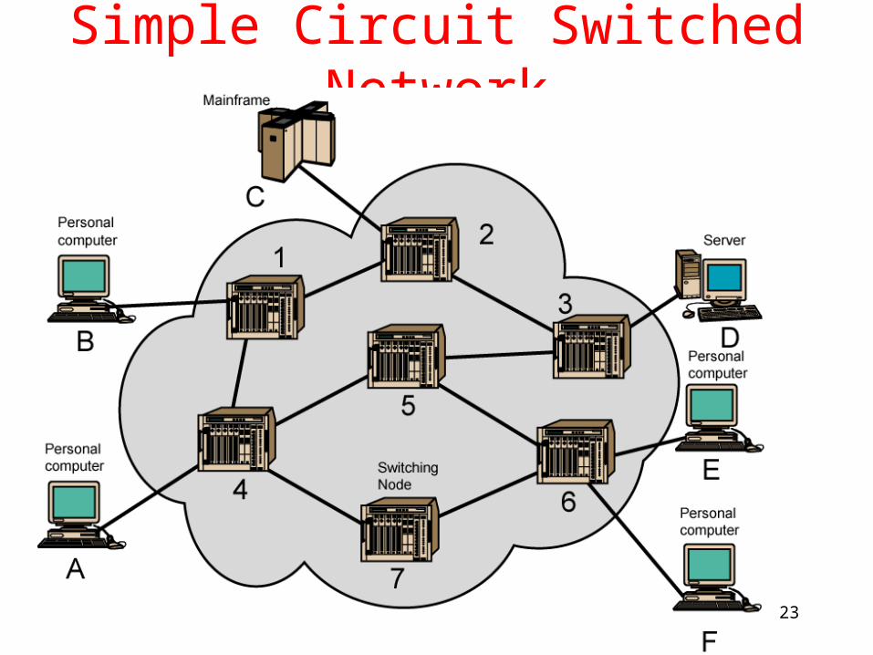
Simple Circuit Switched Network
24
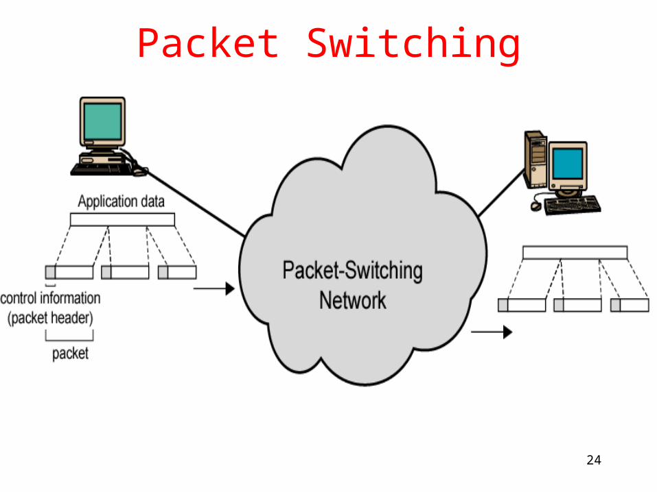
Packet Switching
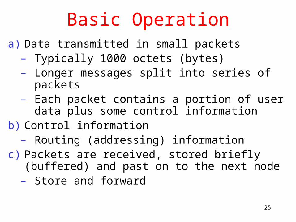
25
Basic Operationa) Data transmitted in small packets
– Typically 1000 octets (bytes)– Longer messages split into series of packets– Each packet contains a portion of user data
plus some control informationb) Control information
– Routing (addressing) informationc) Packets are received, stored briefly (buffered)
and past on to the next node– Store and forward
26
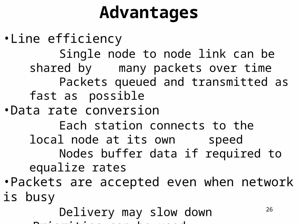
Advantages
•Line efficiencySingle node to node link can be shared by many packets over timePackets queued and transmitted as fast as possible
•Data rate conversionEach station connects to the local node at its
own speedNodes buffer data if required to equalize rates
•Packets are accepted even when network is busyDelivery may slow down
Priorities can be used


