45
1 CHAPTER 5 Advanced Networking Technologies C. Develder and M. Pickavet
| Date post: | 31-Dec-2015 |
| Category: |
Documents |
| Upload: | dominic-mcdonald |
| View: | 216 times |
| Download: | 1 times |

1
CHAPTER 5Advanced Networking Technologies
C. Develder and M. Pickavet

Technologies 2
Content
1. Traffic Engineering
2. Failure Recovery
3. Multicast
4. Ethernet
5. IPv6

Technologies 3
How to route the traffic (or more general: engineer the traffic)?
Now: Shortest path (hop count) routing!
Alternatives:
- Constraint based routing (use other metrics)- Load balancing (use different routes)- MPLS (Multi Protocol Label Switching) as
supportingtechnology
Traffic Engineering

Technologies 4
QoS routing: taking certain constraints into account(bandwidth, delay, cost, …)
CONSTRAINT BASED ROUTING (could be very complex) (additive [hop count, delay], multiplicative [loss rate], concave constraints [bandwidth])
How to distribute “constraint” information? (e.g. BW on links)
Add information on link state during OSPF (Q-OSPF)
CRCR
CRCR
ER ER
Routing table gets much more complex!
low BWfiber link
high BWsatellite link
low delay
High BW
Very useful for both DiffServ and IntServ!
How to find the route with the required QoS?

Technologies 5
Load balancing: distribute traffic more evenly over the network:
- equal cost multipath (use of hash function)- use of MPLS
Shortest path problem: overload certain links
CRCR
CRCR
ER ER
Load balancing
CR

Technologies 6e.g. use for DiffServ
IP payloadIP headerMPLS header
MPLS header (32 bit): Label (20 bit): MPLS labelExp (3 bit): experimental useS (1 bit): stacking bitTTL (8 bit): time to live
3
5
5 4
Label InformationBase (LIB)
Link in Label in Link out Label out
1 5 1 4
2 3 1 5
… … … …
Label SwitchedRouter (LSR)
LSR
IN 1
IN 2 OUT 2
OUT 1
local significance
MPLS: Multi Protocol Label Switching

Technologies 7
Routing <> Label Switching
1
2
3
45
6
7
8
AB
189.123.42.34/16
189.123.0.0 2
189.123.0.0 6
189.123.0.0 8189.123.0.0 B
189.123.0.0 7
B
m
kd
w
kg
g: m 5
m: k 3
k: d 4
d: w 8
w: k B
B k
B m
B d
B w
B k
IP router
IP/MPLS Label Switched Router (LSR)
B g

Technologies 8
MPLS: Path set-up (LSP)
A B
C
D
Y
RSVP-TE
Z
X
W
PATH Lab_Req Y PATH Lab_Req Y
PATH Lab_Req Y
Need label forDestination Y
(LABEL_REQUESTobject in
PATH msg)
PA
TH
Lab
_Req
Y
RESV Lab 300
RE
SV
Lab
100
RESV Lab 100
RESV Lab
200
Respond with alabel (receive)(LABEL objectin RESV msg)
200100
100200300100
100200
100
300
LabelInformation
Base
Label SwitchedRouter
Y: to B Y: to C
Y: to Y
Technologies 11
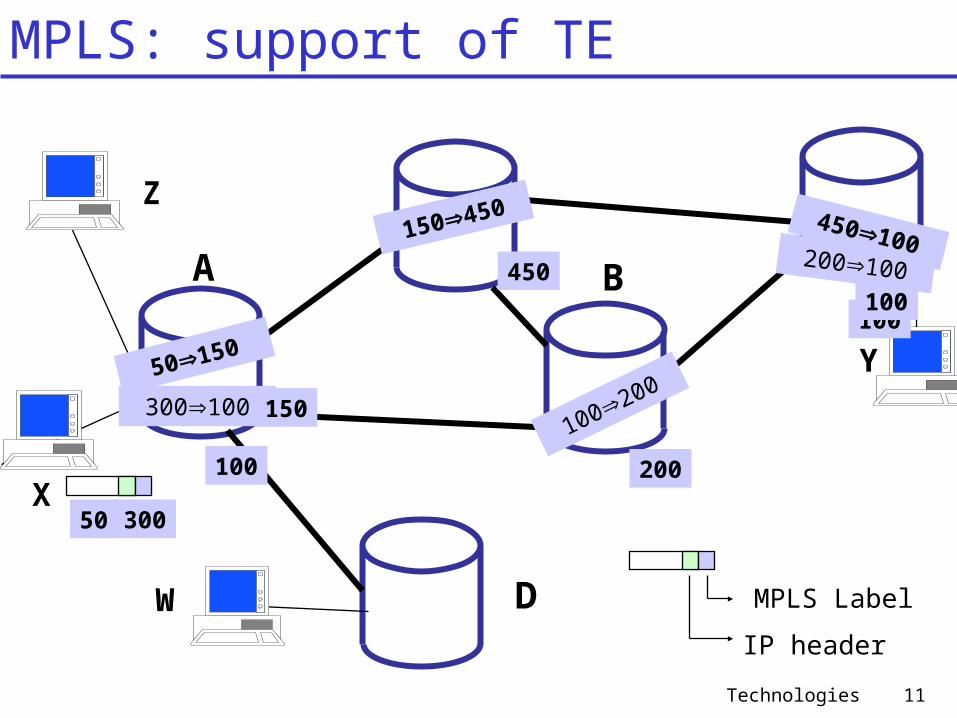
MPLS: support of TE
A B
C
D
Z
X
W MPLS Label
IP header
200100
300100100200
Y50150
150450 450100
300
100 200
100
50
150
450100

Technologies 12
157.193.0.0145.12.0.0
A BF
C
DE
OUT 1
OUT 2
network gateway interface145.12.0.0 B OUT 1
… … …
network gateway interface label145.12.0.0 C OUT 2 5
… … …
5
34
3
LSP
MPLS tunnel (LSP) set-up via explicit routing: during path set-up an explicit path is used
(not the OSPF shortest, but e.g. a constraint based path with lowest delay)
145.12.134.3
MPLS: Example MPLS “tunnel”

Technologies 13
MPLS Virtual Private Network between three company locations
157.193.0.0145.12.0.0
153.145.0.0
Public Internet(MPLS capable)
LSP
MPLS could be combined with DiffServ to provide QoS (the 3 Exp bits are used toindicate the PHB)
easy end-to-endencryption forsecurity
MPLS: VPN example

Technologies 14
Content
1. Traffic Engineering
2. Failure Recovery
3. Multicast
4. Ethernet
5. IPv6

Technologies 15
A B C
E D
Router C: Routing Table
Dest. Nexthop
Interface
A B BCB Direct BCD Direct CDE D CD
knowledge ofnetwork topology
Dijkstra: shortest paths
Router C: Link-State Database
Link Cost SequenceAB 1 A,5AE 1 A,6BD 1 B,6BC 1 B,7CD 1 D,7DE 1 D,6
[AB,BD,BC]
[BD,CD,DE]
[AE,DE]
[AB,AE]
incominglink statepackets
normal operation
Failure Recovery: OSPF based

Technologies 16
Router C: Routing Table
Dest. Nexthop
Interface
A B BCB Direct BCD Direct CDE B BC
knowledge ofnetwork topology
Dijkstra: shortest paths
Router C: Link-State Database
Link Cost SequenceAB 1 A,5AE 1 A,6BD 1 B,6BC 1 B,7CD 1 D,7
[AB,BD,BC]
[BD,CD]
[AE]
[AB,AE]
incominglink statepackets
A B C
E D
Link ED notadvertised
recovery
this may take 50 to 100 seconds
Failure Recovery: OSPF based

Technologies 17
CR
CRCR
CR
ER ER
copy traffic on backup LSP
take traffic frombackup LSP
if primary LSP fails
Set up back-up LSP between edge routersCopy incoming traffic on primary and back-up LSP (1+1 protection)Select traffic from back-up LSP if primary LSP not available VERY FAST (single decision at receiving end = egress router)
Note: all traffic between the two edge routers may be protected with the same back-up LSP
ingressrouter
egressrouter
primaryLSP
backupLSP
Failure Recovery: MPLS based

Technologies 18
MPLS: failure recovery
A B
C
D
Z
X
W MPLS Label
IP header
200100
300100100200
Y50150
150450 450100
300
100 200
100
50
150
450100

Technologies 19
Content
1. Traffic Engineering
2. Failure Recovery
3. Multicast
4. Ethernet
5. IPv6
Technologies 20
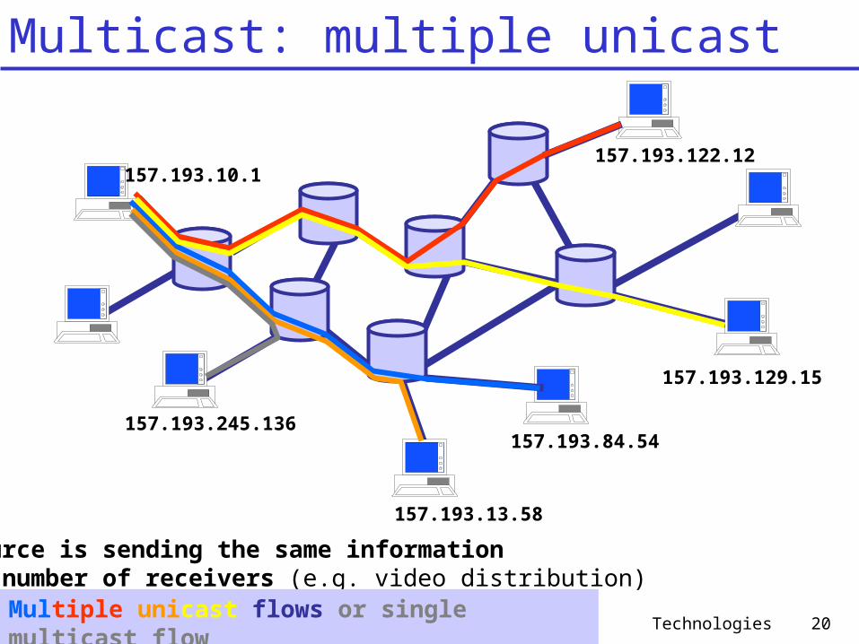
Multicast: multiple unicast
A source is sending the same information to a number of receivers (e.g. video distribution)
Multiple unicast flows or single multicast flow
157.193.122.12
157.193.129.15
157.193.84.54
157.193.13.58
157.193.245.136
157.193.10.1

Technologies 21
Multicast: single multicast tree
Multiple unicast flows or single multicast flow
connection oriented!- requires state in the network- requires signaling- requires special routing protocols
157.193.122.12
157.193.129.15
157.193.84.54
157.193.13.58
157.193.245.136
157.193.10.1157.193.122.12
157.193.129.15
157.193.84.54
157.193.13.58
157.193.245.136
157.193.10.1
226.17.30.197
Class D multicast address( multicast group)
Who belongs to multicast group?
How to become member of the multicast group?
How to set up the multicast tree?

Technologies 22
IGMPInternet Group Management Protocol
(used in a single (sub)network)
Multicast architecture
Internet
MULTICAST ROUTINGDVMRP
Distance Vector Multicast Routing ProtocolPIM
Protocol Independent Multicast(used in a wide area: intradomain)
also interdomain

Technologies 23
Internet Group Management Protocol (IGMP)IGMP messages:
message type sent by purposemembership query : general router ask attached hosts joined multicast groupsmembership query : specific router ask attached hosts specific joined multicast groupmembership report host report host wants to join or is joined to given multicast groupleave group host report leaving multicast group
ERInternet
226.17.30.197 226.17.30.197
226.17.30.197
226.17.32.156
226.17.30.197
226.17.44.23
226.17.44.23
226.17.44.23
226.17.44.23
226.17.32.156
optional! ( soft state)
query
report
Edge Router has to know the multicast groups
where local hostsare subscribed

Technologies 24
Service model of multicast
Service model: - local join of multicast group using IGMP- access router will take care of receiving
multicast group packets (for its local hosts)(use of multicast routing protocol)
- receiver driven joining of a group- senders do not know the receivers- all group members can be sender
Note: no coordination of the choice of a class D address for a multicast group( multiple groups may eventually use the same class D address!)Solution: “source filtering”, as in IGMP v3
Remaining question: How to interconnect the edge routers?Use of multicast routing protocols

Technologies 25
Multicast routing: group shared tree
How to build up the routing tree between edge routers?first approach: multicast group shared tree
Note: all group members use the same (bidirectional) tree
CR
CRCR
CR
CR
ER
ER
ER
ER
ER
ER
ERER
ER
ER
ER

Technologies 26
Multicast routing: group shared tree
How to build up the routing group shared tree?Use of a rendezvous point (center based approach)
Note: choice of rendezvous point is difficult
CR
CRCR
CR
CR
ER
ER
ER
ER
ER
ER
ERER
ER
ER
ER
RP

Technologies 27
Multicast routing: source based tree
CR
CRCR
CR
CR
ER
ER
ER
ER
ER
ER
ER
Second approach: multiple source based treesNote: trees will be different and in general unidirectional

Technologies 28
Multicast routing: source based tree
CR
CRCR
CR
CR
ER
ER
ER
ER
ER
ER
ER
Note: prune messages from edge routers that have no hosts belonging to the multicast group
How to build up a source based tree?Use of a Reverse Path Forwarding (RPF)
An incoming multicast packet is forwarded in a router on all of its outgoing links (except the one on which the packet was received) only if the packet arrived on the link that is on its own shortest pathback to the sender

Technologies 29
Multicast routing: source based tree
CR
CRCR
CR
CR
ER
ER
ER
ER
ER
ER
ER
Prune messages sent from edge routers that have no hosts belonging to the multicast group(“pruned” routers will not forward packets from the multicast group)

Technologies 30
Examples of multicast routing protocols
Protocol Independent Multicast (PIM)Two different scenarios: dense mode and sparse mode
dense mode (DM): large number of users RPF approachsparse mode (SM): few users central approachbidirectional (BIDIR): variant of SM central approach
Distance Vector Multicast Routing Protocol (DVMRP)
source based treesreverse path forwarding, pruning and grafting
Multicast Open Shortest Path First (MOSPF)Core Based Tree (CBT)

Technologies 31
Content
1. Traffic Engineering
2. Failure Recovery
3. Multicast
4. Ethernet
5. IPv6

Technologies 33
X
1 2 3
4
1 2 3
4A B C
D
1 2 3
4
12
3
Y
Send frame from X to YSend frame back from Y to XFill in switch table
Ethernet: Self learning
Ethernet Switch
X 1
Y 3
X 1 X 4X 4
Y 1Y 4

Technologies 35
X
1 2 3
4
1 2 3
4A B
D1
2
Send frame from X to Y
Ethernet: switched loops
Y
Formation of loopsMultiple copies received by terminals
X 1
X 4
X 3
X 1
X 2
X 1
X 4

Technologies 36
with multiple paths, cycles result - switches may multiply and forward frame forever
for increased reliability, desirable to have redundant, alternative paths from source to dest
solution: organize switches in a spanning tree by disabling subset of interfaces
Spanning Tree Protocol (STP)

Technologies 37
Spanning Tree Protocol (STP)
IEEE 802.1D: Spanning Tree Protocol (STP)STP forms a spanning tree where interfaces are blocked to avoid loops in the network
Switches communicate using 2 types of BPDU’s (Bridge Protocol Data Units):- Configuration BPDU’s (at start-up)- Topology Change Notification BPDU’s and their acknowledgements (during operation)
The spanning tree is built automatically STP will also result in a higher reliability

Technologies 38
Spanning Tree Protocol (STP)
Configuration procedure:Step 1: all ports in blocking modeStep 2: choose a root switch Step 3: minimum spanning tree algorithm calculated in a distributed way using the Port Path Costs (cf. Kruskal)
Step 4: ports will change to forwarding mode based on spanning tree
How to choose the root switch?Based on (lowest) Bridge IDBridge ID format:
Bridge priority (2 bytes) MAC address (6 bytes)

Technologies 40
Spanning Tree Protocol: Example
3 2 6 4
5
1 8
7
root
RP
RP
RP
RPRP RP RP
DP DP
DP
DP
DP
DP
DP
DP
DPBP
BPDP
DPBP
DP
BP
DP BP
BP
RP: Root PortDP: Designated PortBP: Blocked Port
hub
switch
router
Technologies 41
Virtual LAN (VLAN)
(Switched) LAN: Local area network where different hosts are interconnected via switches. They can communicate without limitation.
Virtual LAN (VLAN): Defines a subset of the hosts that are able to communicate within a single VLAN. No layer 2 communication between VLAN’s.
VLAN’s allow more flexible management of the network.
Different VLAN implementations: Untagged (port based)Tagged (802.1Q)

Technologies 42
Virtual LAN (VLAN): port basedA port is mapped on a VLAN (VLAN ID),
(typically manual configuration)Ports will communicate only with other ports having the same VLAN IDLogically separate networks (different IP subnets)
traffic between VLAN’s via external routerNo tags are used
1 2 3 4 5 6 7
Example :VLAN 1: ports 1,2,5,7VLAN 2: ports 3,4,6 VLA
N 1
VLA
N 2

Technologies 43
Virtual LAN (VLAN): port based
Multiple VLAN’s require separate portsInterconnection via IP router
A B C
D
VLAN 1VLAN 2VLAN 3
3 separatelinks
3 separatelinks
IP router

Technologies 44
Virtual LAN (VLAN): tagged
Untagged frame: a frame that does not contain a tag header
(tag not necessary in port based VLAN’s)Tagged frame: a frame that contains a tag header immediately following the Source MAC Address field of the frame. There are two types of tagged frames: VLAN-tagged frames and priority tagged frames:
• VLAN-tagged frame: A tagged frame whose tag header carries both VLAN identification and priority information• priority-tagged frame: A tagged frame whose tag header carries priority information, but carries no VLAN identification information (VID = 0)
VLAN-aware: A property of switches or end stations that recognize and support VLAN-tagged frames

Technologies 45
Virtual LAN (VLAN): tagged
Standard IEEE 802.3 Ethernet Frame format
preamble SFD DA SA T/L data FCS
preamble SFD DA SA T/L data FCSTPID TAG
Userpriority
CFIVLAN
identifier
TPID (Tag Protocol Identifier) = 0x8100
CFI (Canonical Format Indicator) = 0 (for ethernet)
SFD (Start-of-Frame Deliniter)
Extra information is inserted

Technologies 46
Virtual LAN (VLAN): tag based
Multiple VLAN’s can use a single port (due to tagging)Interconnection via IP routerAutomatic configuration possible
A B C
D 1 single
link
1 link or3 separate
links

Technologies 47
Content
1. Traffic Engineering
2. Failure Recovery
3. Multicast
4. Ethernet
5. IPv6

Technologies 48
IPv6
Why a new standard?- exhaust of IP address space- learn from experience with IPv4
- Increase address space from 32 bits to 128 bits- Introduce anycast addresses- Use streamlined 40 bytes header- Introduce the notion of a flow (e.g. audio and video flows)- Support traffic classes (see e.g. DSCP in DiffServ)
Example: send request to any server of a certain type,routing system will deliver only to nearest server

Technologies 49
IPv6
payload length (16)
traffic class (8)version(4) flow label (20)
next header (8) hop limit (8)
source address (128 bit)
destination address (128 bit)
payload
IP address: 8 x 16bit numbers in HEXexample: 3FFE:80B0:0:1:A00:20FF:FEA2:8DBC

Technologies 50
IPv6
4-bitversion
4-bitheaderlength
8-bit ToS 16-bit total length of packet
16-bit identification 3-bit flags 13-bit fragmentoffset
8-bit TTL 8-bit protocol 16-bit header checksum32-bit source IP address
32-bit destination IP address
Options (if any)
Data
payload lengthtraffic classversion flow label
next header hop limit
source address (128 bit)
destination address (128 bit)
payload
No fragmentationNo checksumNo options(but possible via next header)Fixed length of
40 bytes
Ipv6 headernext header = TCP TCP+data
Ipv6 headernext header=routing
routing headernext header=TCP
TCP+data
Ipv6 headernext header=routing
routing headernext header=fragment
fragment headernext header=TCP
TCP+data
Routing header: strict or loose source route (similar to IPv4)Fragment header: similar to IPv4


