VNR VIGNANA JYOTHI INSTITUTE OF ENGINEERING AND TECHNOLOGY Department of Automobile Engineering II B.Tech. II Semester (AE) 2016-17 1. Computational Methods 2. Applied Thermodynamics 3. Automotive Engines and Systems 4. Theory of Machines 5. Basic Electrical and Electronics Engineering 6. Machine drawing
Transcript
VNR VIGNANA JYOTHI INSTITUTE OF ENGINEERING AND TECHNOLOGY
Department of Automobile Engineering
II B.Tech. II Semester (AE) 2016-17
1. Computational Methods
2. Applied Thermodynamics
3. Automotive Engines and Systems
4. Theory of Machines
5. Basic Electrical and Electronics Engineering
6. Machine drawing
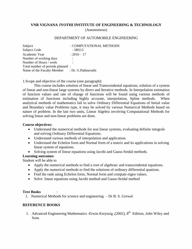
VNR VIGNANA JYOTHI INSTITUTE OF ENGINEERING & TECHNOLOGY
(Autonomous)
DEPARTMENT OF AUTOMOBILE ENGINEERING
Subject : COMPUTATIONAL METHODS
Subject Code : 5BS13
Academic Year : 2016 – 17
Number of working days :
Number of Hours / week :
Total number of periods planned :
Name of the Faculty Member : Dr. G.Padmavathi
1.Scope and objective of the course (one paragraph):
This course includes solution of linear and Transcendental equations, solution of a system
of linear and non-linear large systems by direct and Iterative methods. In Interpolation estimation
of function values and rate of change of functions will be found using various methods of
estimation of functions including highly accurate, interpolation, Spline methods. When
analytical methods of mathematics fail to solve Ordinary Differential Equations of Initial value
and Boundary value Problems type, it may be solved by various Numerical Methods based on
nature of problem. In the last two units, Linear Algebra involving Computational Methods for
solving linear and non-linear problems are done.
Course objectives:
Understand the numerical methods for non linear systems, evaluating definite integrals
and solving Ordinary Differential Equations.
Understand various methods of interpolation and application.
Understand the Echelon form and Normal form of a matrix and its applications in solving
linear system of equations.
Solving system of linear equations using Jacobi and Gauss-Seidal methods.
Learning outcomes:
Student will be able to
Apply the numerical methods to find a root of algebraic and transcendental equations.
Apply the numerical methods to find the solutions of ordinary differential quations.
Find the rank using Echelon form, Normal form and compute eigen values.
Solve linear equations using Jacobi method and Gauss-Seidal method
Text Books :
1. Numerical Methods for science and engineering – Dr B. S. Grewal
5 Transference of a Force from One Plane to Another, Balancing of Several
Masses in Different Planes 2
6 Transference of a Force from One Plane to Another, Balancing of Several
Masses in Different Planes 2
Learning Outcomes
After the completion of Unit V, the student should be able to
Draw the turning movement diagram for flywheel
Gyroscopic effect on naval ship, 4-wheel drive and 2-wheel drive
Balance the un balanced rotating and reciprocating masses in automotive
Cumulative Periods 60
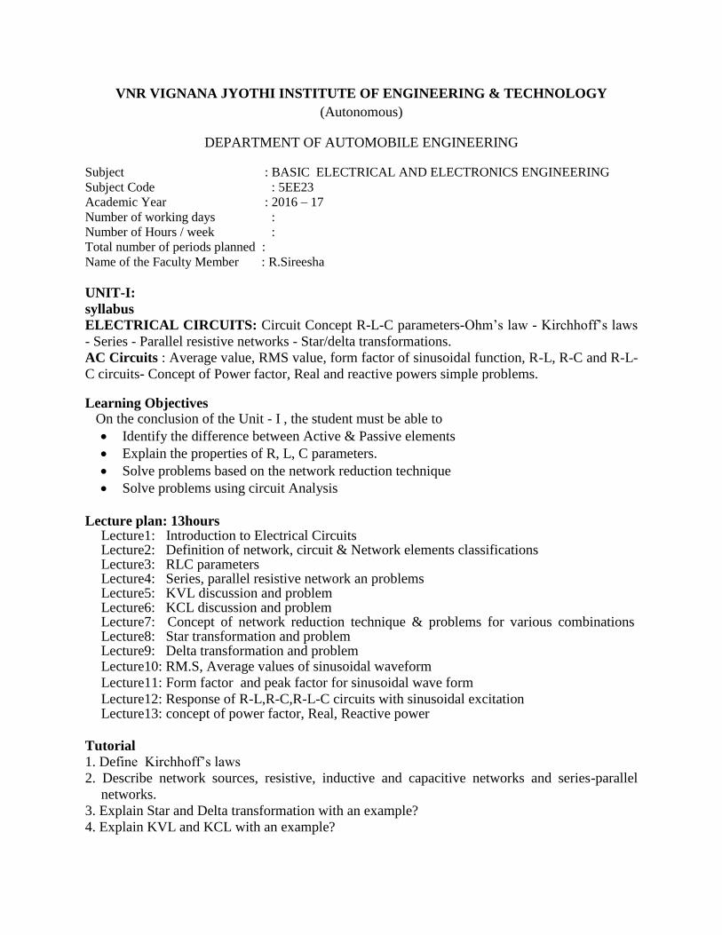
VNR VIGNANA JYOTHI INSTITUTE OF ENGINEERING & TECHNOLOGY
(Autonomous)
DEPARTMENT OF AUTOMOBILE ENGINEERING
Subject : BASIC ELECTRICAL AND ELECTRONICS ENGINEERING
Subject Code : 5EE23
Academic Year : 2016 – 17
Number of working days :
Number of Hours / week :
Total number of periods planned :
Name of the Faculty Member : R.Sireesha
UNIT-I:
syllabus
ELECTRICAL CIRCUITS: Circuit Concept R-L-C parameters-Ohm’s law - Kirchhoff’s laws
- Series - Parallel resistive networks - Star/delta transformations.
AC Circuits : Average value, RMS value, form factor of sinusoidal function, R-L, R-C and R-L-
C circuits- Concept of Power factor, Real and reactive powers simple problems.
Learning Objectives On the conclusion of the Unit - I , the student must be able to
Identify the difference between Active & Passive elements
Explain the properties of R, L, C parameters.
Solve problems based on the network reduction technique
Solve problems using circuit Analysis
Lecture plan: 13hours Lecture1: Introduction to Electrical Circuits Lecture2: Definition of network, circuit & Network elements classifications Lecture3: RLC parameters Lecture4: Series, parallel resistive network an problems Lecture5: KVL discussion and problem Lecture6: KCL discussion and problem Lecture7: Concept of network reduction technique & problems for various combinations Lecture8: Star transformation and problem Lecture9: Delta transformation and problem Lecture10: RM.S, Average values of sinusoidal waveform
Lecture11: Form factor and peak factor for sinusoidal wave form
Lecture12: Response of R-L,R-C,R-L-C circuits with sinusoidal excitation Lecture13: concept of power factor, Real, Reactive power
Tutorial
1. Define Kirchhoff’s laws
2. Describe network sources, resistive, inductive and capacitive networks and series-parallel
networks.
3. Explain Star and Delta transformation with an example?
4. Explain KVL and KCL with an example?
5 An alternating current is expressed as i=14.14sin314t. Determine: a) rms current b) frequency
c) instantaneous current when t = 0.02ms.
6. Give an explanation of analysis of ac circuits with single basic network element taking an
example.
Assignment
1. Define Network & Network elements. 2. Classify network elements based on their properties. 3. Calculate the equivalent resistance for any one type of network. 4. Explain about Active, Reactive and apparent powers. Give expression for the above. 5. Define RMS , average value and form factor of an alternating quantity.
UNIT-II:
Syllabus
DC MACHINES: Principle of operation of DC Generator – emf equation - types – Principle of
operation of DC Motor - DC motor types –torque equation – Three point starter -Swinburne’s
test, applications.
TRANSFORMERS: Principle of operation of single phase transformer–emf equation– losses–
OC and SC tests - efficiency and regulation
Learning Objectives
On the conclusion of the Unit – II, the student must be able to
Explain the principle of operation of DC Generator with types Explain the principle of operation of DC Motor with types Identify the difference between generator and motor Explain the principle of operation of single phase transformer
Lecture Plan : 13 hours
Lecture1&2 : Working principle of DC Generator
Lecture3 : Derivation of EMF Equation with problems Lecture4 : Types of DC generator Lecture 5&6 : Working principle of DC Motor Lecture7 : Derivation of Torque Equation with problems Lecture8 : Maximum Power Transfer Theorem Lecture9 : Three point starter Lecture10 : Swinburne’s test description on DC Motor Lecture11 : Principle of operation of single phase transformer Lecture12 : Derivation of EMF Equation with problems Lecture13 : Efficiency and regulation of single phase transformer
Tutorial
1. Explain the principle of operation of dc motor. 2. A shunt generator delivers 50 kW at 250 V and runs at 400 rpm. The armature and field
resistances are 0.02 Ω and 50 Ω respectively. Calculate the speed of the machine running as
a shunt motor and taking 50 kW input at 250 V. Allow 1 V per brush for contact drop.
3. What are the losses in a transformer and how they vary with load? Deduce a condition for
maximum efficiency.
4. Derive the emf equation of dc generator.
5. Derive the torque equation of dc motor
6. Distingish between dc generator and dc motor.
7. List out Various types of dc generator and dc motor with operation.
Assignment
1. Deduce the relation between induced emf and terminal voltage of separately excited, shunt
and series generators.
2. A 40kVA single phase transformer has core loss of 450W and full load copper loss of
850W. If the power factor of the load is 0.8, calculate (i) full load efficiency, (ii) load
corresponding to maximum efficiency, and (iii) maximum efficiency at unity power factor.
3. Obtain an expression for the load KVA at which maximum efficiency occurs.
UNIT-III:
Syllabus AC MACHINES: Principle of operation of alternator – regulation by synchronous
impedance method –Principle of operation of induction motor – slip – torque
characteristics – applications.
INSTRUMENTS: Principle and construction of permanent magnet moving coil and
moving iron instruments.89
Learning Objectives
On the conclusion of the Unit: III, The student must be able to
Explain the principle of operation of Alternator Solve the alternator problems to find regulation Explain the principle of operation of Induction motor Identify the different types of measuring instruments with working principle.
Lecture plan: 9hours Lecture1&2: working principle of Alternator Lecture3:Constructional details of Alternator Lecture4,5 and 6:problems on Alternator to find regulation Lecture7: working principle of Induction motor Lecture8: Characteristics of Induction motor Lecture9: problems on Induction motor Lecture10:Principle of PMMC Lecture11:Constuctional details of PMMC with torque derivation Lecture12: Principle of MI instrument Lecture13:Constuctional details MI instrument with torque derivation Tutorial 1. Explain the working principle of alternator.
2. A 6 pole alternator runs at 1000 rpm, and supplies power to a 4 pole, 3 phase induction motor.
The frequency of rotor of induction motor is 2 Hz. Determine the slip and speed of the motor.
3. Explain the working principle of a 3 phase induction motor.
4. Explain the working principle of PMMC.
5. Derive the torque equation of PMMC.
6. Explain the working principle of MI.
7. Derive the torque equation of MI.
Assignment
1.Explain why it is not advisable to start a 3 phase induction motor by directly connecting it across the supply. With a circuit diagram? 2.Explain a star – delta starter.
UNIT-IV:
Syllabus
Diode and its characetistics:
Diode equation, Symbol and volt ampere characteristics. Diode applications Half-wave
rectifier, Full-wave rectifier and bridge rectifier(simple problems).
Learning objectives
At the end of completion of all learning activities the student is able to
Explain pn junction diode
Explain forward bias and reverse bias
Explain the V-I characteristics of forward biased pn junction diode
Explain the V-I characteristics of reverse biased pn junction diode
Define static resistance, dynamic resistance and bulk resistance of a diode.
Define reverse saturation current and reverse breakdown voltage of a diode.
Describe current equation of diode.
Explain the current components of a diode
Define transition capacitance and diffusion capacitance of a diode.
Distinguish the features of Si and Ge diodes
Explain the function of rectifier
Explain half wave rectifier and full wave rectifier
Explain the advantages of full wave rectifier over half wave rectifier
Explain the advantage of bridge rectifier
Define and derive Ripple factor, % regulation, efficiency of HWR
Define and derive Ripple factor, % regulation, efficiency of FWR