STRUCTURAL DESIGN CALCULATIONS FOR A NEW LEAN-TO TIMBER FRAMED CARPORT at 1 COPE STREET, WALSALL, WEST MIDLANDS for B M BABBAGE LTD FEBRUARY 2016 Prepared by: Tel: 01543 263554 Ref: H726 Rev 0 Hibberd Consulting Engineers 30 Bore Street Lichfield Staffordshire WS13 6PQ
Transcript
STRUCTURAL DESIGN CALCULATIONS FOR A NEW LEAN-TO
TIMBER FRAMED CARPORT
at
1 COPE STREET, WALSALL, WEST MIDLANDS
for
B M BABBAGE LTD
FEBRUARY 2016
Prepared by:
Tel: 01543 263554
Ref: H726 Rev 0
Hibberd Consulting Engineers
30 Bore Street
Lichfield
Staffordshire
WS13 6PQ
H726 – STRUCTURAL DESIGN CALCULATIONS FOR A NEW LEAN-TO TIMBER
FRAMED CARPORT
CONTENTS
Section Page
Structural Synopsis 1/01
Codes of Practice 1/02
Sketch plan and elevations SK/01
Loading schedule 2/01
Roof support timber members 3/01 - 10
Longitudinal stability (diaphragm wall) 4/01 - 02
1/01 STRUCTURAL DESIGN SYNOPSIS
HCE are appointed by BM Babbage Ltd to provide structural design for a new carport at 1
Cope Street, Walsall.
The carport will be timber framed and is to be constructed as a lean-to structure against the
existing house.
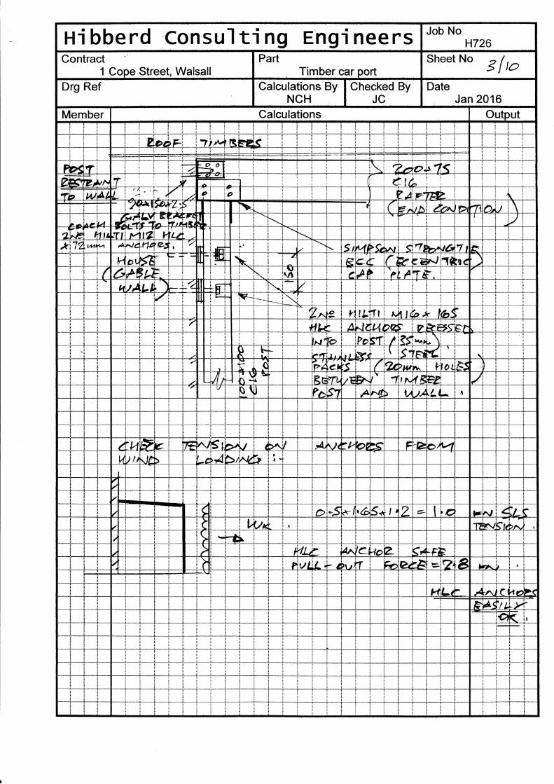
The bitumen felted plyboard roof deck will be supported by timber purlins, spanning between
timber nominally pitched rafters. In turn, the rafters will be supported at the top by proprietary
joist hangers onto the existing masonry wall forming the gable elevation of the house and at
the bottom by timber posts, which will bear onto nominal concrete pad base foundations.
The overall longitudinal stability of the structure will be generated by plywood sheathing
diaphragm action within two of the four side elevation structural bays. Lateral frame stability
will be provided by attachment of the rafters to the main house, combined with roof deck
effective diaphragm action.
The external side and rear elevations are to be clad using timber weather-boarding. This will
be supported and restrained by timber rails fixed to the main timber frame posts, or by fixing
via battens onto the diaphragm studs.
These structural calculations were prepared only for the design of the new carport.
Prior to ordering any new materials referred to within these calculations, the contractor must
record his own site dimensions and also refer to the Architect’s drawings. References to mm
and m dimensions and levels within these calculations concern only the analysis and
mathematical techniques used to determine the appropriate section sizes and overall stability.
These calculations are not intended for measurement, ordering materials of specific length,
cutting sections to length or setting out any aspect of the structure.
1/02
CODES OF PRACTICE
BS 5268:2-2002 Structural use of Timber – Code of Practice for Permissible
Stress Design, Materials and Workmanship.
BS 5268:6.1-1996 Code of practice for the design of timber frame walls.
BS 6399:3-1988 Code of Practice for imposed roof loads.
BS 648: 1964 Schedule of weights of building materials.
loa*C%aT26,/Y yA
ONP
ryPar^1T5
,
I T---l i--_--l I
01
7oa,*15 e&,
k
rrCEl'nf
PROPOSED FLOOR PLAN]ea$e€.)4pstS
PROPOSED REAR ELEVATION
E/\rD T,*o B/LrS - ).5o,^,, pr6r1",*f^ FtP ?ryUA,Dr*?ktzil-*4 To 'd^€B F*Eg - 75^^*lu,^t- ESuxphtrW NApS AT lfua^ fff To Sfu>St bS,fS tfi#D rl,f +SoLg ?LT
.
LLF+nc,
rt lextooTAST
"JfYtsB I
hbouring Brick Wall
ng Engif,ontractI t Cope_Stfeet,Walsall ___l
n 2016
Pavement
?S*Fq,rLr'
?t ArnB.t/.r?\aa{ (
lSlnlt4il,4lf.f,P^rF
oot-
U)'oo-oo
F
oz
EE*o=6obocE8gEOE-o(gEqFP
oo-o
-6t I7 t7
E;tNDF E l*FTtr{, artaI
EEo6OB
_ln*.lr&-
. a_ i a IT
Timber car port
Job No
sheet No sF{, I
Cope Street
S:' i ! i i I ! i i i
Hi bberd consul ti ng Engi nee rs Ilou No
H726Contract
l Cope Street, WalsallPart sheet No
z /orTimber car portDrg Ref Calculations By
NCHChecked
JCBy Date
Jan 2016Member Calculations Output
LriAI!rnta iki'-l.l HE UIt-t
+-L ---$,
e z
cG t W:l
f .*t 71rtrb__l ?N , JE7t *t,-t rd io
( McIMI
l#y:t NIA"tt
-s
L i' 13\ i--it:
7t1ictr) f.., CTl z) iU,2t*Nir{Ut >M Ir -!>Ftrb/ rZ E o tC s
) 2LqI 'l-J ,4r {-
lL, 3n I
7orcF: IM ?a aa->E Da I A4 AuL
3
9cDt:
brl tlVJL DI?.rlrT l e ,75 E .{l Ilrr
)]
I
47-
l.r )Al>Ltr.ftlr-, Bt=a e h ilN D ,A/ia tlt' r4 :
ti,JJ >w o ,tSI Yubr / ?pS f,S c JC bi *rt rS 3- d '*ilDbfu (Oq) .( t),)tA
Calculations for timber joists are in accordance with BS5268:Pt 2:2002 Joist size - 47 wide x 100 deep Timber type - Sawn Softwood as Table NA.2 of BS EN 336 Span of joist = 1.65 m Span type - Simple End bearing - left hand end X = 0 mm Y = 50 mm - right hand end X = 0 mm Y = 50 mm End notches - left hand end - none specified - right hand end - none specified Joist centres = 400 mm Strength class from Table 8 (service classes 1 & 2) - C16 Service class - 2 (Covered and heated or unheated) Maximum design moment = 0.4 kNm/m Design shear force at left hand support = 0.97 kN/m Design shear force at right hand support = 0.97 kN/m Load Description Type A B C Gk Qk
DEAD + IMPOSED UDL 0 1.65 0.43 0.75
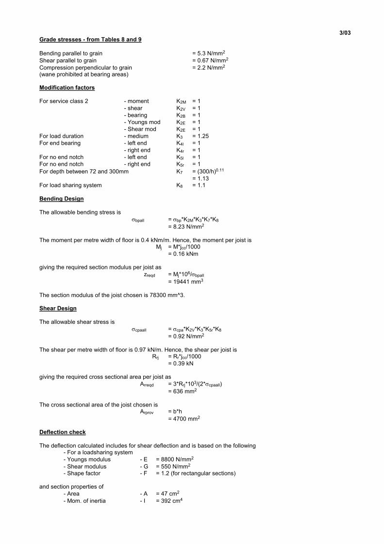
3/03 Grade stresses - from Tables 8 and 9
Bending parallel to grain = 5.3 N/mm2
Shear parallel to grain = 0.67 N/mm2
Compression perpendicular to grain = 2.2 N/mm2 (wane prohibited at bearing areas) Modification factors
For service class 2 - moment K2M = 1
- shear K2V = 1
- bearing K2B = 1
- Youngs mod K2E = 1
- Shear mod K2E = 1
For load duration - medium K3 = 1.25
For end bearing - left end K4l = 1
- right end K4r = 1
For no end notch - left end K5l = 1
For no end notch - right end K5r = 1
For depth between 72 and 300mm K7 = (300/h)0.11
= 1.13 For load sharing system K8 = 1.1
Bending Design
The allowable bending stress is
σbpall = σbp*K2M*K3*K7*K8
= 8.23 N/mm2 The moment per metre width of floor is 0.4 kNm/m. Hence, the moment per joist is Mj = M*jcc/1000
= 0.16 kNm giving the required section modulus per joist as
zreqd = Mj*106/σbpall
= 19441 mm3 The section modulus of the joist chosen is 78300 mm^3. Shear Design
The allowable shear stress is
σcpaall = σcpa*K2V*K3*K5r*K8
= 0.92 N/mm2 The shear per metre width of floor is 0.97 kN/m. Hence, the shear per joist is Rrj = Rr*jcc/1000
= 0.39 kN giving the required cross sectional area per joist as
Arreqd = 3*Rrj*103/(2*σcpaall)
= 636 mm2 The cross sectional area of the joist chosen is Arprov = b*h
= 4700 mm2 Deflection check
The deflection calculated includes for shear deflection and is based on the following - For a loadsharing system
- Youngs modulus - E = 8800 N/mm2
- Shear modulus - G = 550 N/mm2 - Shape factor - F = 1.2 (for rectangular sections) and section properties of
- Area - A = 47 cm2
- Mom. of inertia - I = 392 cm4
3/04
The maximum calculated deflection is 1.4 mm. The allowable deflection in accordance with clause 2.10.7 is 5 mm (0.003*span). The section PASSES all checks
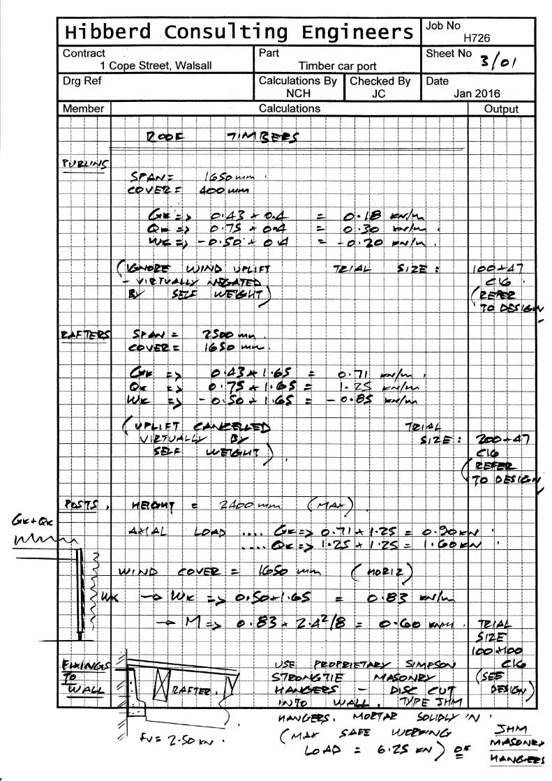
PURLINS: USE 100x47 C16 at 400mm CRS. Fix plywood deck down onto purlins.
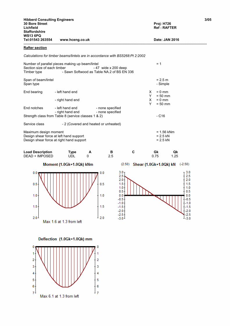
Calculations for timber beams/lintels are in accordance with BS5268:Pt 2:2002 Number of parallel pieces making up beam/lintel = 1 Section size of each timber - 47 wide x 200 deep Timber type - Sawn Softwood as Table NA.2 of BS EN 336 Span of beam/lintel = 2.5 m Span type - Simple End bearing - left hand end X = 0 mm Y = 50 mm - right hand end X = 0 mm Y = 50 mm End notches - left hand end - none specified - right hand end - none specified Strength class from Table 8 (service classes 1 & 2) - C16 Service class - 2 (Covered and heated or unheated) Maximum design moment = 1.56 kNm Design shear force at left hand support = 2.5 kN Design shear force at right hand support = 2.5 kN Load Description Type A B C Gk Qk
DEAD + IMPOSED UDL 0 2.5 0.75 1.25
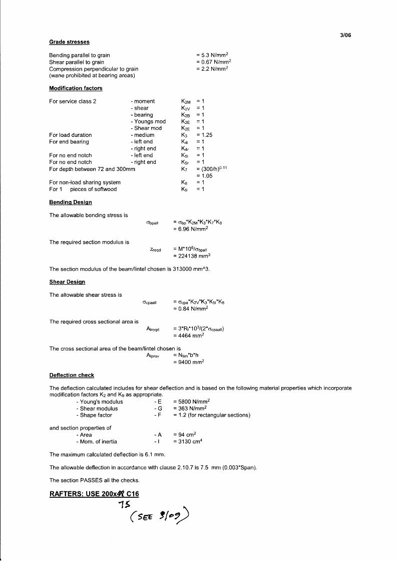
3/06Grade stresses
Bending parallel to grainShear parallel to grainCompression perpendicular to grain(wane prohibited at bearing areas)
Modification factors
For service class 2
For load durationFor end bearing
For no end notchFor no end notch
- moment- shear- bearing- Youngs mod- Shear mod- medium- left end- right end- left end- right end
= 5.3 N/mm2
= 0.67 N/mm2
= 2.2 Nlmmz
= 1.25
= (300/h)011
= 1.05_4-t-a-t
Kznr
KzvKzeKzeKzeKsK+r
furKst
Ks,.
Kt
Ke
Ks
For depth between 72 and 300mm
For non-load sharing systemFor 1 pieces of softwood
Bgndiqq Dqsiqn
The allowable bending stress is6bpall
The required section modulus isZreqd
= tlbp*K2M*Ks*Kz*Ka
= 6.96 N/mm2
= M*106/ogp211
= 224138 mm3
The section modulus of the beam/lintel chosen is 313000 mm^3.
Shear Desiqn
The allowable shear stress is
6cpaall = o"pa*K2v"Kg*Kst*Ke
= 0.84 N/mm2
= 3*Rr*103/(2*ocpaal)
= 4464 mm2
The required cross sectional area is
Atreqd
The cross sectional area of the beam/lintel chosen isAtpro, = Ntim*b*h
= 9400 mmz
Deflectign check
The deflection calculated includes for shear deflection and is based on the following material properties which incorporatemodification factors Kz and Ks as appropriate.
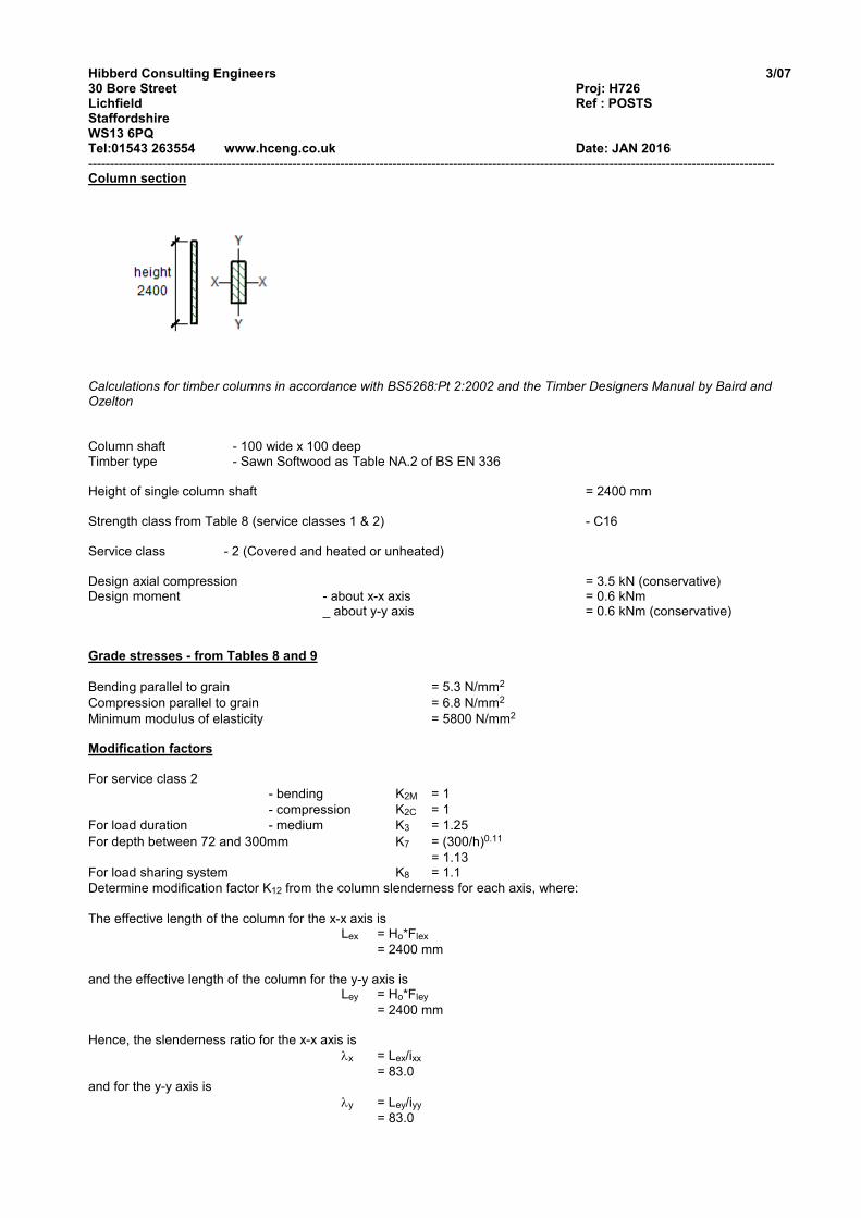
Calculations for timber columns in accordance with BS5268:Pt 2:2002 and the Timber Designers Manual by Baird and Ozelton Column shaft - 100 wide x 100 deep Timber type - Sawn Softwood as Table NA.2 of BS EN 336 Height of single column shaft = 2400 mm Strength class from Table 8 (service classes 1 & 2) - C16 Service class - 2 (Covered and heated or unheated) Design axial compression = 3.5 kN (conservative) Design moment - about x-x axis = 0.6 kNm _ about y-y axis = 0.6 kNm (conservative) Grade stresses - from Tables 8 and 9
Bending parallel to grain = 5.3 N/mm2
Compression parallel to grain = 6.8 N/mm2
Minimum modulus of elasticity = 5800 N/mm2 Modification factors
For service class 2 - bending K2M = 1
- compression K2C = 1
For load duration - medium K3 = 1.25
For depth between 72 and 300mm K7 = (300/h)0.11
= 1.13 For load sharing system K8 = 1.1
Determine modification factor K12 from the column slenderness for each axis, where:
The effective length of the column for the x-x axis is Lex = Ho*Flex
= 2400 mm and the effective length of the column for the y-y axis is Ley = Ho*Fley
= 2400 mm Hence, the slenderness ratio for the x-x axis is
λx = Lex/ixx
= 83.0 and for the y-y axis is
λy = Ley/iyy
= 83.0
3/08
and from Table 22 for compression members - x-x axis K12x = 0.44
- y-y axis K12y = 0.44
The maximum slenderness ratio does not exceed 180. The section can be used for members complying with clause 2.11.4(a),(b),(c) and (d). Determine Axial Stresses
The minimum value of K12 is for the y-y axis, hence, the allowable compressive stress is
σcpaall = σcpa*K2C*K3*K8*K12
= 4.12 N/mm2 The applied compressive stress is
σcpaapp = N*103/(b*h)
= 0.35 N/mm2 Determine Bending Stresses
The allowable bending stress is
σbpall = σbp*K2M*K3*K7*K8
= 8.23 N/mm2 The applied bending stress about the x-x axis is
σbpappx = Mxx*106/Zxx
= 3.59 N/mm2 The applied bending stress about the y-y axis is
σbpappy = Myy*106/Zyy
= 3.59 N/mm2 Combining Axial and Bending Stresses
Using the interaction formula described in clause 2.11.6, with the Euler critical stress
σe = (π2*E)/λmax2
= 8.31 N/mm2 and the Euler coefficient
Ke = 1-(1.5*σcpaapp*K12/σe)
= 0.972 the combined effect of axial load and bending is
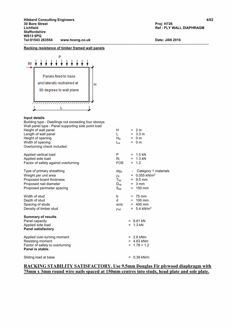
-------------------------------------------------------------------------------------------------------------------------------------------------------------- Racking resistance of timber framed wall panels
Input details
Building type - Dwellings not exceeding four storeys Wall panel type - Panel supporting side point load Height of wall panel H = 2 m Length of wall panel L = 3.3 m Height of opening Hw = 0 m
Width of opening Lw = 0 m
Overturning check included. Applied vertical load P = 1.5 kN Applied side load Rf = 1.3 kN
Factor of safety against overturning FOS = 1.2 Type of primary sheathing styp - Category 1 materials
Weight per unit area ρp = 0.055 kN/m2
Proposed board thickness Tbp = 9.5 mm
Proposed nail diameter Dnp = 3 mm
Proposed perimeter spacing Spp = 150 mm
Width of stud b = 75 mm Depth of stud d = 100 mm Spacing of studs scrs = 400 mm