Abstract— This paper discusses full-dimension multiple-input-multiple-output (FD-MIMO) technology, which is currently anactive area of research and standardization in wireless commu-nications for evolution toward Fifth Generation (5G) cellularsystems. FD-MIMO utilizes an active antenna system (AAS) witha 2-D planar array structure that not only allows a large numberof antenna elements to be packed within feasible base stationform factors, but also provides the ability of adaptive electronicbeamforming in the 3-D space. However, the compact structure oflarge-scale planar arrays drastically increases the spatial correla-tion in FD-MIMO systems. In order to account for its effects, thegeneralized spatial correlation functions for channels constitutedby individual elements and overall antenna ports in the AAS arederived. Exploiting the quasi-static channel covariance matricesof users, the problem of determining the optimal downtilt weightvector for antenna ports, which maximizes the minimum signal-to-interference ratio of a multi-user multiple-input-single-outputsystem, is formulated as a fractional optimization problem.A quasi-optimal solution is obtained through the application ofsemi-definite relaxation and Dinkelbach’s method. Finally, theuser-group specific elevation beamforming scenario is devised,which offers significant performance gains as confirmed throughsimulations. These results have direct application in the analysisof 5G FD-MIMO systems.
Index Terms— Full-dimension multiple-input-multiple-output(FD-MIMO), elevation beamforming, spatial correlation, fifthgeneration (5G), active antenna system (AAS).
I. INTRODUCTION
MULTIPLE-INPUT multiple-output (MIMO) technologyhas remained a subject of interest in the last two
decades due to its ability to cope with the increase in the
Manuscript received April 22, 2017; revised August 29, 2017; acceptedOctober 6, 2017. Date of publication October 13, 2017; date of currentversion February 14, 2018. The work of Q.-U.-A. Nadeem, A. Kammoun andM.-S. Alouini was supported by a CRG4 grant from the Office of CompetitiveResearch Funding (OCRF) at KAUST. The work of Mérouane Debbah wassupported by the ERC Starting Grant 305123 MORE (Advanced Mathemat-ical Tools for Complex Network Engineering). This paper was presentedat the IEEE Global Communications Conference, Washington, DC, USA,in December 2016. The associate editor coordinating the review of thispaper and approving it for publication was X. Yuan. (Corresponding author:Qurrat-Ul-Ain Nadeem.)
Q.-U.-A. Nadeem, A. Kammoun, and M.-S. Alouini are with the Computer,Electrical, and Mathematical Sciences and Engineering Division, King Abdul-lah University of Science and Technology, Thuwal 23955-6900, Saudi Arabia(e-mail: [email protected]; [email protected];[email protected]).
M. Debbah is with Centrale Supélec, 91192 Gif-sur-Yvette, France, andalso with the Mathematical and Algorithmic Sciences Laboratory, HuaweiFrance R&D, 92100 Paris, France (e-mail: [email protected];[email protected]).
Color versions of one or more of the figures in this paper are availableonline at http://ieeexplore.ieee.org.
Digital Object Identifier 10.1109/TCOMM.2017.2762685
wireless data traffic and improve the reliability of wirelesssystems. In order to be compatible with the existing 3rdGeneration Partnership Project (3GPP) Long Term Evolution(LTE) standard, most of the existing MIMO implementationsconsider the deployment of fewer than ten linearly placedantennas at the base station (BS) [1]. The correspondingimprovement in spectral efficiency, although important, is stillrelatively modest and can be vastly improved by scaling upthese systems by possibly orders of magnitude. This has ledto the introduction of massive MIMO systems, that servemany users in the same time-frequency resource using low-complexity signal processing methods [2]–[4].
While massive MIMO technology is a key enabler fornext generation cellular systems, there are still many practicalchallenges down the road to its successful deployment [2], [4].One main challenge is that the number of antennas thatcan be equipped at the top of BS towers is limited bythe BS form factors and operating LTE carrier frequencies.To circumvent this difficulty, the 3GPP has proposed the useof a 2D uniform planar array which can be readily installedin practice as compared to the conventional uniform lineararray (ULA) [5]–[7]. For example, a 16 × 16 uniform planararray with half wavelength inter-element spacing occupiesabout 1m×1m space at the typical LTE carrier frequency of2.5 GHz. By contrast, about 15m spacing is required in thehorizontal direction to install a linear array of 256 antennas,which is not feasible given the limited installation space atBS towers.
In addition to the emergence of large-scale antenna arrays,the cell site architecture itself has evolved in the last decadefrom the one wherein the base transceiver station (BTS)equipment is located away from the passive antenna elementarray, to the one wherein the analogue portion of the BTS,comprising of amplifiers and phase shifters, is located in theremote radio head closer to the passive antenna elements.The next stage is the integration of the active transceiverunit array into the passive antenna element array, resultingin an active antenna system (AAS) [8], [9]. The AAS cansupport adaptive electronic beamforming by controlling thephase and amplitude weights applied to individual antennaelements. The use of an AAS with a 2D planar array structureresults in full-dimension (FD) MIMO, which was identified asa promising technology for 5G cellular systems in the 3GPPRelease-12 workshop in 2012 [10]. Follow-up study items areunder completion [11] and formal standardization is beingdone in Release-13.
NADEEM et al.: DESIGN OF 5G FULL DIMENSION MASSIVE MIMO SYSTEMS 727
FD-MIMO has three important distinguishing features ascompared to the conventional LTE systems. Firstly, the num-ber of antennas supported within feasible BS form factors,indicated in [12, Table II], has increased due to the 2Dplanar structure of the antenna arrays. Secondly, the 2Darrangement of active antenna elements provides the abilityof adaptive electronic beam control over both the elevationand the traditional azimuth dimensions [13], [14]. The radioresource is organized on the basis of antenna ports, whereeach port is mapped to a group of physical antenna elementsarranged in the vertical direction [7]. Controlling the phaseand amplitude weights applied to these elements allows for thedynamic adaptation of the vertical dimension of the antennaport radiation pattern. This technology, referred to as elevationbeamforming, enables more directed and spatially separatedtransmissions to a large number of users [8], [9], [15]–[17].Thirdly, the FD-MIMO architecture lends itself to a hybriddigital analog implementation, where the the multi-user (MU)MIMO precoding stage is implemented in the baseband andthe elevation beamforming stage is implemented in the analogdomain [18], [19].
The hybrid implementation helps reduce the channel stateinformation (CSI) feedback overhead, which is prohibitivelyhigh when implementing fully digital MU-MIMO beamform-ing techniques in massive MIMO systems. In an attempt toreduce this feedback overhead, the authors in [20] exploit thesparsity in millimeter wave (mmWave) channels as well asthe notion of compressive sensing to design a low-complexitybeam selection method that does not require explicit channelestimation. Other works [18], [21] employ channel dimension-ality reduction techniques before the MU precoding stage. TheFD-MIMO active antenna arrays realize this channel dimen-sion reduction in the elevation beamforming stage, where thedowntilt weight vectors are used to group antenna elementsinto a reduced number of antenna ports. The digital precodingstage then requires the estimation of the reduced-dimensioneffective channel.
The additional control over the elevation dimension inFD-MIMO systems enables a variety of strategies such assector-specific and user-specific elevation beamforming, andcell splitting [13], [22], [23]. The authors in [17] used laband field trials to show that 3D beamforming can achievesignificant performance gains in real indoor and outdoordeployments, by adapting the vertical dimension of the antennaport radiation pattern at the BS individually for each useraccording to its location. Some 3D beamforming designs wereproposed in [15] for a single user multiple-input-single-output(MISO) system, wherein the authors used the approximateantenna port radiation pattern expressions from [24], [25]to find the optimal downtilt angle. This approach, also usedin works dealing with multi-user scenarios [23], [26], [27],abstracts the role played by physical elements constituting anantenna port in performing the downtilt by approximating thevertical radiation pattern of each port by a narrow beam in theelevation. The actual radiation pattern depends on the num-ber of elements constituting the port, their patterns, relativepositions and corresponding weights [7], [11]. More sophisti-cated elevation beamforming methods need to be developed
that depend directly on the underlying structure of theport.
This paper discusses the design of the 2D active antennaarray for FD-MIMO implementation. The array constitutes ofcolumns of active antenna elements, where each column isreferred to as an antenna port and is fed with a correspondingdowntilt weight vector to steer the vertical radiation pattern ofthat port in the targeted direction. In our study of FD-MIMOsystems, we make three main contributions which are summa-rized as follows.
• Compact structure of large-scale antenna arrays dras-tically increases the spatial correlation in FD-MIMOsystems, making it imperative to account for it in thedesign of elevation beamforming algorithms. The existingstudies on antenna correlation consider passive antennaelements arranged in the azimuth plane only [28]–[32].In this work, we derive the exact spatial correlationfunction (SCF) for the 3D channels constituted by indi-vidual antenna elements in the 2D AAS by expandingthe array response of each antenna element using thespherical harmonic expansion (SHE) of plane waves. TheSCF is presented in Theorem 1. The analysis followsthe guidelines in [33], where we derived the SCF fora ULA of antenna ports using the approximate antennaport radiation pattern expression from [24]. The finalanalytical expression depends on the angular parametersand the geometry of the array through the Fourier series(FS) coefficients of the power spectra. The correlationbetween the antenna ports is then expressed as a functionof the correlation matrix of the elements constituting theports and their corresponding downtilt weight vectors.
• The main objective of this article is to study the per-formance benefits of FD-MIMO techniques by devisingefficient elevation beamforming algorithms that optimizethe downtilt weight vectors of the antenna ports, utilizingthe quasi-static channel correlation matrices of the usersobtained using the derived SCF. The weight vectors thatmaximize the signal-to-noise ratio (SNR) of a single userMISO system are presented in Theorem 2. The downlinkof a multi-user MISO system is studied next under theassumption that all antenna ports transmit using the samedowntilt weight vector. The problem of determining thisvector that maximizes the minimum signal-to-interferenceratio (SIR) of the system is formulated as a fractionaloptimization problem, for which a quasi-optimal solu-tion is obtained through the application of semi-definiterelaxation and Dinkelbach’s method, as summarized inAlgorithm 1. This scenario is referred to as single down-tilt beamforming (SDB).
• Finally, we devise a user-group specific single down-tilt beamforming (UG-SDB) scenario in Algorithm 2,wherein the user population is partitioned into groupsbased on the users’ quasi-static channel correlation matri-ces and each user-group is served by a subset of antennaports that transmit using a quasi-optimal downtilt weightvector. Nam et al. have proposed two user-groupingschemes based on the users’ channel correlation matricesin [21] - the K-means clustering and the fixed quantization
728 IEEE TRANSACTIONS ON COMMUNICATIONS, VOL. 66, NO. 2, FEBRUARY 2018
method. Our user-grouping method is motivated by thelatter. Simulations results show that even the SDB sce-nario yields significant performance gains when com-pared to the existing elevation beamforming methods inliterature, while user-group specific beamforming furtherimproves the system performance.
The rest of this article is organized as follows. Section IIdiscusses the design of the 2D AAS for FD-MIMO imple-mentation and presents the corresponding 3D channel model.In section III, the exact SCFs for channels constituted bythe individual antenna elements and the overall antenna portsare derived. Section IV presents the elevation beamformingalgorithms that optimize the downtilt weight vectors of theantenna ports in the single user and multi-user MISO settings.User-group specific single downtilt beamforming scenario isdevised in section V. Section VI provides simulation resultsand finally, in section VII some concluding remarks are drawn.
II. ANTENNA CONFIGURATION AND 3D CHANNEL MODEL
The idea of exploiting the elevation domain of the channelfor performance optimization has led to the development ofFD-MIMO systems. The recent reports on FD-MIMO envisionthat an AAS, utilizing a large number of antenna elementsarranged in a 2D planar array structure, can be designed torealize spatially separated transmission links to a large numberof users. In this section, we introduce this 2D AAS and outlinethe corresponding FD-MIMO channel model.
A. Active Antenna Array for FD-MIMO
In order to realize the performance benefits of FD-MIMOtechniques, an efficient implementation of an AAS with a2D planar array structure is a key requirement. The AASis an advanced BS technology, which integrates the activetransceiver unit array into the passive antenna element array,allowing the gain, beamwidth and downtilt of the transmitbeam to be controlled adaptively by active electronic com-ponents connected directly to each element [8], [9]. Theseactive antenna elements should be placed in both the verticaland horizontal directions to provide the ability of adaptiveelectronic beamforming in the elevation and the traditionalazimuth dimensions.
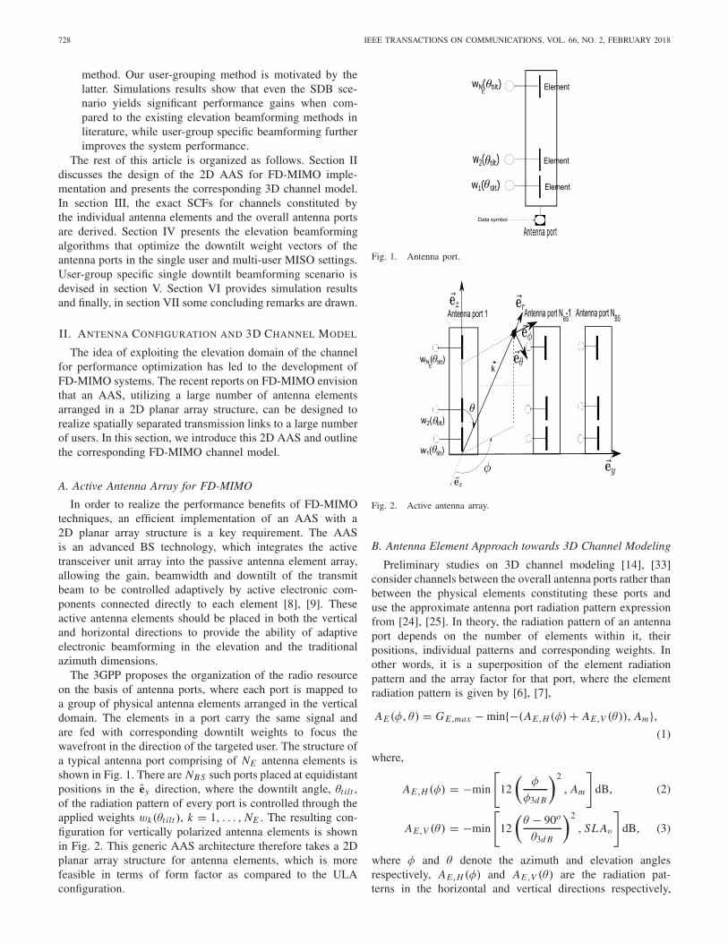
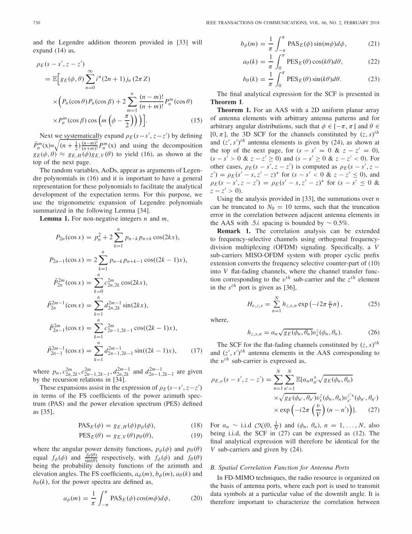
The 3GPP proposes the organization of the radio resourceon the basis of antenna ports, where each port is mapped toa group of physical antenna elements arranged in the verticaldomain. The elements in a port carry the same signal andare fed with corresponding downtilt weights to focus thewavefront in the direction of the targeted user. The structure ofa typical antenna port comprising of NE antenna elements isshown in Fig. 1. There are NBS such ports placed at equidistantpositions in the ey direction, where the downtilt angle, θt ilt ,of the radiation pattern of every port is controlled through theapplied weights wk(θt ilt ), k = 1, . . . , NE . The resulting con-figuration for vertically polarized antenna elements is shownin Fig. 2. This generic AAS architecture therefore takes a 2Dplanar array structure for antenna elements, which is morefeasible in terms of form factor as compared to the ULAconfiguration.
Fig. 1. Antenna port.
Fig. 2. Active antenna array.
B. Antenna Element Approach towards 3D Channel Modeling
Preliminary studies on 3D channel modeling [14], [33]consider channels between the overall antenna ports rather thanbetween the physical elements constituting these ports anduse the approximate antenna port radiation pattern expressionfrom [24], [25]. In theory, the radiation pattern of an antennaport depends on the number of elements within it, theirpositions, individual patterns and corresponding weights. Inother words, it is a superposition of the element radiationpattern and the array factor for that port, where the elementradiation pattern is given by [6], [7],
where φ and θ denote the azimuth and elevation anglesrespectively, AE,H (φ) and AE,V (θ) are the radiation pat-terns in the horizontal and vertical directions respectively,
NADEEM et al.: DESIGN OF 5G FULL DIMENSION MASSIVE MIMO SYSTEMS 729
GE,max is the maximum directional element gain, φ3d B andθ3d B are the half power beamwidths in the azimuth and ele-vation domains respectively, Am is the maximum attenuationand SL Av is the vertical side lobe attenuation level. Theglobal field pattern of a vertically polarized antenna element
in linear scale is√
AE (φ, θ)|lin=
√10
GE,max10 gE (φ, θ), where
gE (φ, θ) ≈ gE,H (φ)gE,V (θ) with,
gE,H (φ) = exp
(−1.2
(φ
φ3d B
)2
ln 10
), (4)
gE,V (θ) = exp
(−1.2
(θ − 90o
θ3d B
)2
ln 10
). (5)
The overall array radiation pattern is a function of this indi-vidual element radiation pattern and the array factor matrix,A, for the AAS given by [7],
A = W ◦ V, (6)
where ◦ is the Hadamard product, V is a NE × NBS matrixcontaining the array responses of the individual radiationelements with each entry given as,
[V]z,s = exp(ik.xz,s), z = 1, . . . , NE , s = 1, . . . , NBS ,(7)
where . is the scalar dot product, xz,s is the location vectorof the zth antenna element in the sth Tx antenna port, andk is the Tx wave vector, where k = 2π
λ v, with v being theunit wave vector. For the configuration shown in Fig. 2, everyentry of V will have a form given by,
[V]z,s(φ, θ)
= exp(
i2π((s−1)
dy
λsin φ sin θ+(z−1)
dz
λcos θ
)), (8)
where dy is the horizontal separation between the antennaports and dz is the vertical separation between the antennaelements, with the phase reference at the origin.
Also W is a NE × NBS matrix comprising of the weightsto be applied to the individual radiation elements. The 3GPPTR36.873 [6] and TR37.840 [7] assume the magnitude of theweights to be identical for each radiation element, while thephase is used to implement the electrical downtilt. Denotingthe (z, s)th entry of W as wz
s , the 3GPP proposed expressionfor wz
s is,
wzs = 1√
NEexp
(−i2π(z − 1)
dz
λcos θt ilts
), (9)
where θt ilts is the downtilt angle for the sth port, definedbetween 0o and 180o. Denoting the (z, s)th entry of V asvz
s (φ, θ), the small-scale 3D channel constituted by the BSantenna port s is given as,
[h]s =NE∑
(z∈port s)=1
wzs
N∑n=1
αn
√gE (φn, θn)v
zs (φn, θn), (10)
= wTs
N∑n=1
αn
√gE (φn, θn)vs(φn, θn), s = 1, . . . , NBS,
(11)
where N is the number of propagation paths, φn and θn arethe azimuth and elevation angle of departure (AoD) of the nth
path respectively, and αn ∼ i.i.d CN (0, 1N ) is the amplitude of
the nth path. Also ws is the weight vector for the sth antennaport, given by the sth column of W, and vs(φn, θn) is thesth column of V. The channel with a given antenna port istherefore a weighted sum of the channels with the NE elementsinside it.
III. SPATIAL CORRELATION FUNCTION
The compact structure of FD-MIMO arrays dramaticallyincreases the spatial correlation between the antenna ports,which is a function of the correlation between the elementsconstituting these ports. In order to realistically evaluate theperformance of FD-MIMO techniques, we derive generalizedanalytical expressions for these SCFs, considering arbitraryAoD distributions and antenna patterns.
A. Spatial Correlation Function for Antenna Elements
Using the antenna element radiation pattern expressionsgiven in (4) and (5) and the array response expression givenin (8), and for αn ∼ i.i.d CN (0, 1
N ) random variables, theSCF for the channels constituted by (z, s)th and (z�, s�)th
antenna elements in the AAS, where z, z� = 1, . . . , NE ,s, s� = 1, . . . , NBS , is expressed as,
ρE (s − s�, z − z�)= E[gE (φ, θ)vz
s (φ, θ)vz�∗s � (φ, θ)],
= E
[gE (φ, θ) exp
(i2π[dy
λ(s − s�) sin φ sin θ
+ dz
λ(z − z�) cos θ
])]. (12)
In order to obtain an analytical expression for ρE (s−s�, z−z�),an approach similar to the one used in [33] will be adopted.The main difference is that here we work with a 2D antennaarray instead of a linear array, which makes the analysismore involved. As a starting point, let Z y = (s − s�) dy
λ and
Zz = (z − z�) dzλ , and define Z =
√Z2
y + Z2z and,
β =
⎧⎪⎪⎪⎪⎨⎪⎪⎪⎪⎩
0, if s − s� = 0&z − z� = 0,
arctan
(Z y
Zz
), if s − s� > 0&z − z� ≥ 0,
π + arctan
(Z y
Zz
), if s − s� ≥ 0&z − z� < 0.
(13)
With these definitions and reformulations, (12) can beexpressed as,
ρE (s − s�, z − z�) = E
[gE (φ, θ) exp
(i2π Z
[cos θ cos β
+ sin θ sin β cos(φ − π
2
) ])]. (14)
Observe that cos θ cos β + sin θ sin β cos(φ − π
2
)is the
dot product of v with spherical coordinates (φ, θ) and xwith spherical coordinates (π/2, β), where x is the locationvector between the (z, s)th and (z�, s�)th antenna elementsin the AAS. Exploiting results on the SHE of plane waves
730 IEEE TRANSACTIONS ON COMMUNICATIONS, VOL. 66, NO. 2, FEBRUARY 2018
and the Legendre addition theorem provided in [33] willexpand (14) as,
ρE (s − s�, z − z�)
= E
[gE (φ, θ)
∞∑n=0
i n(2n + 1) jn (2π Z)
×(
Pn(cos θ)Pn(cos β) + 2n∑
m=1
(n − m)!(n + m)! Pm
n (cos θ)
×Pmn (cos β) cos
(m(φ − π
2
)) )]. (15)
Next we systematically expand ρE (s−s�, z−z�) by defining
Pmn (x)=
√(n + 1
2 ) (n−m)!(n+m)! Pm
n (x) and using the decompositiongE (φ, θ ) ≈ gE,H (φ)gE,V (θ) to yield (16), as shown at thetop of the next page.
The random variables, AoDs, appear as arguments of Legen-dre polynomials in (16) and it is important to have a generalrepresentation for these polynomials to facilitate the analyticaldevelopment of the expectation terms. For this purpose, weuse the trigonometric expansion of Legendre polynomialssummarized in the following Lemma [34].
Lemma 1. For non-negative integers n and m,
P2n(cos x) = p2n + 2
n∑k=1
pn−k pn+k cos(2kx),
P2n−1(cos x) = 2n∑
k=1
pn−k pn+k−1 cos((2k − 1)x),
P2m2n (cos x) =
n∑k=0
c2m2n,2k cos(2kx),
P2m−12n (cos x) =
n∑k=1
d2m−12n,2k sin(2kx),
P2m2n−1(cos x) =
n∑k=1
c2m2n−1,2k−1 cos((2k − 1)x),
P2m−12n−1 (cos x) =
n∑k=1
d2m−12n−1,2k−1 sin((2k − 1)x), (17)
where pn, c2m2n,2k, c2m
2n−1,2k−1, d2m−12n,2k and d2m−1
2n−1,2k−1 are givenby the recursion relations in [34].
These expansions assist in the expression of ρE (s−s�, z−z�)in terms of the FS coefficients of the power azimuth spec-trum (PAS) and the power elevation spectrum (PES) definedas [35],
PASE (φ) = gE,H (φ)pφ(φ), (18)
PESE (θ) = gE,V (θ)pθ (θ), (19)
where the angular power density functions, pφ(φ) and pθ (θ)
equal fφ(φ) and fθ (θ)sin(θ) respectively, with fφ(φ) and fθ (θ)
being the probability density functions of the azimuth andelevation angles. The FS coefficients, aφ(m), bφ(m), aθ (k) andbθ (k), for the power spectra are defined as,
aφ(m) = 1
π
∫ π
−πPASE (φ) cos(mφ)dφ, (20)
bφ(m) = 1
π
∫ π
−πPASE (φ) sin(mφ)dφ, (21)
aθ (k) = 1
π
∫ π
0PESE (θ) cos(kθ)dθ, (22)
bθ (k) = 1
π
∫ π
0PESE (θ) sin(kθ)dθ. (23)
The final analytical expression for the SCF is presented inTheorem 1.
Theorem 1. For an AAS with a 2D uniform planar arrayof antenna elements with arbitrary antenna patterns and forarbitrary angular distributions, such that φ ∈ [−π, π] and θ ∈[0, π], the 3D SCF for the channels constituted by (z, s)th
and (z�, s�)th antenna elements is given by (24), as shown atthe top of the next page, for (s − s� = 0 & z − z� = 0),(s − s� > 0 & z − z� ≥ 0) and (s − s� ≥ 0 & z − z� < 0). Forother cases, ρE (s − s�, z − z�) is computed as ρE (s − s�, z −z�) = ρE (s� − s, z� − z)∗ for (s − s� < 0 & z − z� ≤ 0), andρE (s − s�, z − z�) = ρE (s� − s, z� − z)∗ for (s − s� ≤ 0 &z − z� > 0).
Using the analysis provided in [33], the summations over ncan be truncated to N0 = 10 terms, such that the truncationerror in the correlation between adjacent antenna elements inthe AAS with .5λ spacing is bounded by ∼ 0.5%.
Remark 1. The correlation analysis can be extendedto frequency-selective channels using orthogonal frequency-division multiplexing (OFDM) signaling. Specifically, a Vsub-carriers MISO-OFDM system with proper cyclic prefixextension converts the frequency selective counter-part of (10)into V flat-fading channels, where the channel transfer func-tion corresponding to the v th sub-carrier and the zth elementin the sth port is given as [36],
Hv,z,s =N∑
n=1hz,s,n exp
(−i2π vV n), (25)
where,
hz,s,n = αn√
gE (φn, θn)vzs (φn, θn). (26)
The SCF for the flat-fading channels constituted by (z, s)th
and (z�, s�)th antenna elements in the AAS corresponding tothe v th sub-carrier is expressed as,
ρE,v (s − s�, z − z�) =N∑
n=1
N∑n�=1
E[αnα∗n�√
gE (φn, θn)
×√gE (φn� , θn�)vzs (φn, θn)v
z�∗s � (φn� , θn�)
× exp(−i2π
( v
V
)(n − n�)
)]. (27)
For αn ∼ i.i.d CN (0, 1N ) and (φn , θn), n = 1, . . . , N , also
being i.i.d, the SCF in (27) can be expressed as (12). Thefinal analytical expression will therefore be identical for theV sub-carriers and given by (24).
B. Spatial Correlation Function for Antenna Ports
In FD-MIMO techniques, the radio resource is organized onthe basis of antenna ports, where each port is used to transmitdata symbols at a particular value of the downtilt angle. It istherefore important to characterize the correlation between
NADEEM et al.: DESIGN OF 5G FULL DIMENSION MASSIVE MIMO SYSTEMS 731
the overall antenna ports in terms of the correlation betweenthe underlying physical elements constituting the ports and thecorresponding downtilt weights.
From (10) it is evident that the SCF for the channels con-stituted by any two antenna ports, s and s�, will be a functionof the correlations between all the elements constituting theseports and the weight functions applied to these elements as,
ρ(s, s�) = E[[h]s[h]Hs � ] =
NE∑z=1
NE∑z�=1
wzs w
z�∗s � E[gE (φ, θ)
×vzs (φ, θ)vz�∗
s � (φ, θ)],
=NE∑z=1
NE∑z�=1
wzs w
z�∗s � ρE (s − s�, z − z�), (28)
for s, s� = 1, . . . , NBS , where ρE (s − s�, z − z�) is given by(24). The NBS × NBS correlation matrix for the antenna ports
constituting the AAS can therefore be written as,
RBS = WH
RE W, (29)
where W is a NBS NE × NBS block diagonal matrix of theweight vectors applied to the NBS antenna ports given by,
WH =
⎡⎢⎢⎢⎣
w1H 01×NE 01×NE (NBS−2)
01×NE w2H 01×NE (NBS−2)
. . .
01×NE 01×NE (NBS−2) wNBSH
⎤⎥⎥⎥⎦, (30)
where ws is the NE ×1 weight vector for the sth antenna portand RE is the NBS NE × NBS NE correlation matrix for all theelements constituting the AAS defined as,
[RE ](s �−1)NE +z�,(s−1)NE +z = ρE (s − s�, z − z�), (31)
for z, z� = 1, . . . , NE , s, s� = 1, . . . , NBS , whereρE (s − s�, z − z�) is given by (24). With this formulation,[RBS]s �,s = ρ(s, s�).
732 IEEE TRANSACTIONS ON COMMUNICATIONS, VOL. 66, NO. 2, FEBRUARY 2018
Fig. 3. Validation of the proposed SCF.
Fig. 4. Effect of NE on correlation.
In order to validate the proposed SCF, all antenna portsare assumed to transmit at a downtilt angle of θt ilts = 90o,s = 1, . . . , NBS . The elevation angles are generated accord-ing to Laplacian density spectrum, with mean AoD θ0 andspread σt . The azimuth angles are generated using Von Misesdistribution, with mean μ and spread ∝ 1/κt . The parametervalues are set as N0 = 30, σt = 15o, θ0 = 100o, κt = 10 andμ = π/3. The validation of the theoretical result in (28), whereρE (s−s�, z−z�) is computed using (24), is done by comparisonwith the Monte-Carlo simulated correlation. The Monte Carlosimulations are performed over 100000 realizations of (12) toobtain the simulated ρE (s − s�, z − z�). The results are shownin Fig. 3 for NE = 10, NBS = 8 and dy = dz = 0.5λ. Thederived theoretical result provides a perfect fit to the MonteCarlo simulated correlation for only 30 summations over n. InFig. 4, the correlation is seen to decrease with increasing NE .The reason is attributed to the fact that for higher NE , the mainlobe of the antenna port radiation pattern is narrower. As aconsequence, the energy of a higher number of propagationpaths is not captured by the Tx beam, resulting in a decreasein the Tx power and correlation. Increasing dz will also reducethe correlation for similar reasons. The correlation betweenantenna ports therefore depends on the underlying arrangementof the antenna elements constituting these ports, i.e. the valuesof NE , dz and downtilt weights.
IV. PERFORMANCE OPTIMIZATION
OF FD-MIMO SYSTEMS
The previous section expressed the spatial correlationbetween the antenna ports as a function of the correlations
between the elements constituting the ports and the downtiltweight vectors applied to these ports. In this section, weoptimize the downtilt weight vectors to maximize the downlinkSNR and SIR in the single user and multi-user MISO settingsrespectively. Existing works on 3D beamforming optimize thedowntilt angle utilizing the approximate antenna port radiationpattern expressions from ITU report [15], [26], [37]. Thiswork makes use of the exact radiation pattern expressionsthat depend on the values of NE , dz , and the downtiltweights, and proposes solutions for the downtilt weight opti-mization problem. From here on, the focus is on FD-MISOsettings and Rayleigh correlated channel coefficients given asfollows.
Assumption A-1. The channel vector, h ∈ CNBS×1, for a
user equipped with a single isotropic Rx antenna element andserved by a NE × NBS AAS deployed at the BS is modeled as,
h = R12BSz, (32)
where z has i.i.d zero mean, unit variance complex Gaussianentries and RBS is the user’s channel correlation matrix givenby RBS = WH RE W, where W and RE are defined in (30) and(31) respectively. The channel correlation matrix satisfies thecondition,
lim supNBS
||RBS|| < +∞. (33)
Optimizing the downtilt weights directly using the ray-tracingmodel in (10) is a difficult task, given the explicit dependenceof the channel on the number of paths and associated small-scale parameters (AoDs, powers). The model outlined inAssumption A-1 will allow us to exploit tools from randommatrix theory (RMT) to propose solutions for the optimaldowntilt weight vectors. Moreover, it was shown in [33] thatboth the parametric channel model in (10) and the correlationbased model in (32) give similar results in rich scatteringenvironments.
The optimization of the downtilt angles θt ilts of thes = 1, . . . , NBS antenna ports using the 3GPP proposedexpression for the weight functions in (9) is not tractable,because of the non-linear relationship between θt ilts and wz
s .Instead, this work exploits the linear dependence of the chan-nel in (11) on the downtilt weight vector ws and optimizesthe elements of this weight vector directly, allowing themto take arbitrary unequal values. The proposed algorithmsin the subsequent sections of this work will not yield asimilar structure for the downtilt weight vectors as the onegiven in (9) but will result in elevation domain beams thatyield significant performance gains when compared to existingelevation beamforming methods in literature.
Before formulating the optimization problems for the down-tilt weight vectors, an important trace lemma is recalled thatplays a key role in the problem formulations and analysis.
Lemma 2 ([38, Lemma 14.2]). Let A ∈ CN×N and
x = [x1, . . . , xN ]T ∈ CN×1 be a random vector of i.i.d.
entries independent of A, such that E[xi ] = 0, E[|xi |2] = 1,E[|xi |8] < ∞, and lim supN ||A|| < ∞. Then,
1N xH Ax − 1
N tr Aa.s.−−−−→
N→∞ 0. (34)
NADEEM et al.: DESIGN OF 5G FULL DIMENSION MASSIVE MIMO SYSTEMS 733
A. Elevation Beamforming in a Single-User MISO System
The downlink of a single-cell MISO system is consideredfirst, where a NE × NBS AAS at the BS serves a singleuser equipped with a single Rx antenna element. The receivedcomplex baseband signal y at the user is given by,
y = √�hH x + n, (35)
where x ∈ CNBS×1 is the Tx signal from the AAS, hH ∈
C1×NBS is the channel vector from the BS to the user given
by (32) and n ∼ CN (0, σ 2n ) is the additive white Gaussian
noise (AWGN) with variance σ 2n at the user. Also � is given as,
� = PT x × PL × SF × 10GE,max
10 , (36)
where PL is the path loss experienced by the user, SF is theshadow fading and PT x is the transmitted power. The downlinkSNR for the user is then given as,
γ = �
σ 2n
tr(hhH ). (37)
We are interested in finding the SNR maximizing NE × 1weight vectors ws , s = 1, . . . , NBS , that form the W matrixdefined in (30). The optimization problem is formulated asfollows.
Problem (P1):
maximizew1,w2,...,wNBS
γ (38)
subject to ||ws ||2 = 1, for s = 1, . . . , NBS . (39)
The constraint in (39) ensures that the total power of everyantenna port is bounded and does not grow indefinitely withthe number of elements stacked in a port. This problem hasa simple solution in the large (NBS, NE ) regime given in thefollowing theorem.
Theorem 2. Consider a single user system consisting of aBS equipped with a NE × NBS AAS serving a single-antennauser with the channel covariance matrix RBS . Then in thelarge (NBS, NE ) regime, the optimal 3D beamforming weightvectors w∗
s can be computed as,
w∗s = vλmax (RE
ss ), s = 1, . . . , NBS , (40)
where vλmax (REss)
is the eigenvector corresponding to the maxi-
mum eigenvalue λmax of REss , where RE
ss is a NE × NE matrixgiven by RE ([(s − 1)NE + 1 : s NE ], [(s − 1)NE + 1 : s NE ]),for RE defined in (31), such that,
REss
12 w∗
s =√
λmax(REss)w
∗s . (41)
Physically, REss is the correlation matrix formed by the
elements of port s and is therefore given by the sth NE × NE
diagonal matrix of RE . The proof is postponed to AppendixA.
B. Elevation Beamforming in a Multi-User MISO System
The downlink of a multi-user MISO system is considerednext, where a NE × NBS AAS serves K non-cooperatingsingle-element users. The BS uses linear precoding in thedigital domain to mitigate inter-user interference. The pre-coding vector and the data symbol for user k are denoted
as gk ∈ CNBS×1 and sk ∼ CN (0, 1) respectively. The BS
transmits the NBS × 1 signal,
x =K∑
k=1
gksk = Gs, (42)
where G is the NBS × K precoding matrix and s is the K × 1vector of data symbols. The received complex baseband signalat the user k, yk , is given by,
yk =K∑
l=1
√�khH
k gl sl + nk, (43)
where hHk ∈ C
1×NBS is the channel vector from the BS to the
user k defined using (32) as hk = RBS
12k zk .
Every per user channel correlation matrix RBSk is givenby RBSk = W
HRE
k W as defined in (29), where W is theweight matrix defined in (30) and RE
k is the user k’s elementscorrelation matrix with each entry given as,
[REk ](s �−1)NE +z�,(s−1)NE +z = ρEk (s − s�, z − z�), (44)
for z, z� = 1, . . . , NE , s, s� = 1, . . . , NBS , where ρEk (s −s�, z − z�) is computed using (24) for user k. Also nk ∼CN (0, σ 2
n ) is the AWGN with variance σ 2n at user k and �k is
computed using (36) for user k.Remark 2. The computation of ρEk (s − s�, z − z�) requires
the computation of FS coefficients of the power spectra foruser k. The FS coefficients of the PES for user k, (aθk , bθk )computed using any popular distribution, will depend onlyon the mean elevation AoD/line of sight (LoS) angle of userk and the elevation angular spread at the BS. Similarly, theFS coefficients of the PAS for user k (aφk , bφk ) will dependonly on the mean azimuth AoD/LoS angle of user k and theazimuth angular spread at the BS. Therefore the correlationmatrices vary across the users through their mean elevationand azimuth AoDs, which are used to determine the FScoefficients, aφk , bφk , aθk and bθk , for k = 1, . . . , K , that arethen plugged into (24).
Linear precoding schemes are generally asymptotically opti-mal in the large (NBS, K ) regime and robust to CSI imper-fections [2], [3]. However, the complexity of computing theseschemes is prohibitively high in the large (NBS, K ) regime. Anotable exception is maximum ratio transmission (MRT) [39],which is a popular scheme for large scale MIMO systemsdue to its low computational complexity, robustness, and highasymptotic performance [2]. Therefore, we focus on MRTprecoding given by the conjugate of the channel vector hH
kas,
gk = βhk, (45)
where β is chosen to satisfy the Tx power constrainttr(GGH ) = 1 as,
β = 1√tr(HHH )
, (46)
where H = [h1h2 . . . hK ].
734 IEEE TRANSACTIONS ON COMMUNICATIONS, VOL. 66, NO. 2, FEBRUARY 2018
The SINR and rate of user k are defined respectively as,
SI N Rk = hHk gkgH
k hk∑Kl �=k hH
k glgHl hk + σ 2
ρk
, (47)
rk = log2(1 + SI N Rk ) (48)
With MRT precoding, the SINR can be written as,
SI N Rk = |hHk hk |2∑K
l �=k hHk hlhH
l hk + σ 2
β2ρk
, (49)
An asymptotic analysis of this quantity would yield adeterministic approximation for the SI N R in the large(NBS, NE , K ) regime as stated in the following proposition.
Proposition 1. Consider a multi-user MISO system con-sisting of a BS equipped with a NE × NBS AAS serving Knon-cooperating users with channel correlation matrices RBSk ,k = 1, . . . , K , that satisfy the condition in Assumption A-1.Then in the large (NBS , NE , K ) regime, the SI N R convergesas (50), as shown at the bottom of the next page.
The proof of Proposition 1 is provided in Appendix B.Now given that RBSk = W
HRE
k W as defined in (29),(30), and (44), the SINR converges in the large (NBS , NE , K )as (51), as shown at the bottom of the next page, where ws
and ws � are the NE × 1 weight vectors for the antenna ports sand s� that form the block diagonal matrix W in (30), RE
k,ss isa NE × NE matrix given by RE
k ([(s − 1)NE + 1 : s NE ], [(s −1)NE + 1 : s NE ]), where RE
k is defined in (44). SimilarlyRE
k,ss � is a NE × NE matrix given by REk ([(s − 1)NE + 1 :
s NE ], [(s� − 1)NE + 1 : s�NE ]).Note that RE
k,ss � refers to the cross-correlation matrixbetween the elements of port s and port s�, given by the(s, s�)th NE × NE block matrix of RE
k .1) Problem Formulation: The focus of this section is
on interference limited systems, so the performance metricemployed is the max min SIR, which provides a good bal-ance between system throughput, user fairness, and compu-tational complexity. The deterministic approximation for SIRusing (51) is given as,
SI Rk − ( 1NBS
∑NBSs=1 wH
s REk,ssws)
2
1N2
BS
∑Kl �=k∑NBS
s,s �=1 wHs RE
k,ss �ws �wHs � RE
l,s �sws
a.s.−−→ 0,
(52)
The optimization problem is formulated as,Problem (P2):
maximizew1,w2,...wNBS
minimizek∈{1,...,K }
(∑NBS
s=1 wHs RE
k,ssws)2∑K
l �=k∑NBS
s,s �=1 wHs RE
k,ss �ws �wHs � RE
l,s �sws
(53)
subject to ||ws ||2 = 1, s ∈ {1, . . . , NBS}. (54)
The problem of optimizing the beamforming weightsthrough joint max-min problem formulations has been consid-ered in [40], where the problem of multi-cast beamformingwith different receiver groups was shown to be NP-hardand was solved quasi-optimally using semi-definite relaxation(SDR). The problem at hand is much harder because it
considers the joint optimization of different weight vectorsfor different antenna ports. Even after applying SDR and sub-stituting the positive semi-definite rank-one matrix wswH
s ∈C
NE ×NE for a positive semi-definite matrix Ws ∈ CNE ×NE of
arbitrary rank, the relaxed problem is not tractable because ofthe product of Ws and Ws � in the denominator of the objectivefunction. In order to enable a tractable relaxation, all theantenna ports are assumed to transmit using the same optimaldowntilt weight vector. Dropping the subscripts s and s�, theresulting problem is given as,
Problem (P3):
maxw
mink∈{1,...,K }
(∑NBS
s=1 tr(wwH REk,ss))
2∑Kl �=k∑NBS
s,s �=1 tr(wwH REk,ss �wwH RE
l,s �s)
(55)
subject to tr(wwH ) = 1. (56)
This is a basic elevation beamforming scenario referred toas single downtilt beamforming (SDB). Now substituting thepositive semi-definite rank-one matrix wwH ∈ C
NE ×NE inProblem (P3) for a positive semi-definite matrix W ∈ C
NE ×NE
of arbitrary rank, the semi-definite relaxed problem is given as,Problem (P4):
maxW
mink∈{1,...,K }
(∑NBS
s=1 tr(WREk,ss))
2∑Kl �=k∑NBS
s,s �=1 tr(WREk,ss �WRE
l,s �s)(57)
subject to W � 0, tr(W) = 1. (58)
Problem (P4) is efficiently solved using fractional program-mings tools as discussed now.
2) Optimization Technique and Solution: Fractional pro-gramming provides efficient tools to maximize the minimumof ratios in which the numerator is a concave function, thedenominator is a convex function, and the constraint set isconvex, whereas no low-complexity optimization method isavailable if any of these properties is not met [41], [42].An efficient method to do so is the generalized Dinkelbach’salgorithm, discussed in Appendix A of [42]. In order tomeet the conditions for application of Dinkelbach’s method,Problem (P4) is reformulated as,
Problem (P5):
maxW
mink∈{1,...,K }
∑NBSs=1 tr(WRE
k,ss)√∑Kl �=k∑NBS
s,s �=1 tr(WREk,ss �WRE
l,s �s)(59)
subject to W � 0, tr(W) = 1. (60)
The objective function in (59) considers a set of ratios oftwo functions, where we denote the numerator by fk(W) andthe denominator by gk(W), k = 1, . . . , K . In order to studythese functions, the following properties of the vec functionare exploited.
Lemma 3. For any matrix A ∈ CM×N , the vec operator is
NADEEM et al.: DESIGN OF 5G FULL DIMENSION MASSIVE MIMO SYSTEMS 735
Algorithm 1 Single Downtilt Beamforming (SDB)1: procedure GENERALIZED DINKELBACH(W)2: Set > 0;3: Initialize λ = 0;4: repeat5: W∗ = max
W∈CNE ×NE{ min1≤k≤K
[ fk(W) − λgk(W)]},where fk(W) and gk(W) are given by
(64) and (66) respectively, subject toW � 0 and tr(W) = 1;
6: F = min1≤k≤K { fk(W∗) − λgk(W∗)};7: λ = min1≤k≤K fk(W∗)/gk(W∗);8: until F < .9: procedure GAUSSIAN RANDOMIZATION(w)
10: for l = 1 to L11: Generate ζ l ∼ CN (0, W∗);12: Construct a feasible solution wl = sgn(ζ l)/
√NE ;
13: end for14: Determine l∗ = max
l=1,...,Lmin
1≤k≤KSI Rk(wl), where SI Rk
is given by (55);15: w∗ = wl∗ .
tr(AT BCDT ) = vec(A)T (D ⊗ B)vec(C), (63)
∀A, B, C, D ∈ CM×M .
Exploiting these properties, fk(W) and gk(W) can beexpressed as,
fk(W) =NBS∑s=1
vec(WT )T vec(REk,ss). (64)
gk(W) =
√√√√√ K∑l �=k
NBS∑s,s �=1
vec(WT )T (REl,s �s
T ⊗REk,ss �)vec(W)
(65)
= ||⎛⎝ K∑
l �=k
NBS∑s,s �=1
(REl,s �s
T ⊗ REk,ss �)
⎞⎠
12
vec(W)||2. (66)
It can be seen from (64) that fk(W) is a linear functionof W. Also gk(W) is a convex function, expressed as anL2 norm in (66). Problem (P5) therefore considers a set ofratios { fk(W)
gk(W) }Kk=1, where each ratio has an affine numerator
fk(W), convex denominator gk(W) and convex constraintsand can therefore be solved using the generalized Dinkelbach’salgorithm [42]. The Dinkelbach’s procedure to solve Problem(P5) is formulated in Algorithm 1. Once the optimal W∗ isobtained, the corresponding weight vector w that solves theProblem (P3) needs to be extracted. Generally the resultingmatrix W∗, although globally optimal for Problem (P5) has
a rank greater than one and therefore yields a quasi-optimalsolution for Problem (P3). It is important to post-process therelaxed solution W∗ to extract a close to optimal w∗. Besidesthe eigenvector approximation method, where w∗ is approx-imated as the principal eigenvector of W∗, randomization isanother way to extract an approximate solution from the SDRsolution W∗. The idea is to generate a random vector ζ ∈C
NE ×1 ∼ CN (0, W∗) and use it to construct an approximatesolution to Problem (P3). The procedure and theoretical accu-racy results have been discussed in [40], [44]. The specificdesign of the randomization procedure is problem-dependentand has been summarized at the end of Algorithm 1.
The proposed SDB algorithm splits downlink beamforminginto two linear stages: an elevation beamforming stage thatdepends only on the users’ channel correlation matrices tomaximize the minimum user SIR of the system and the MRTprecoding stage for the effective channels with dimensionreduced from NBS NE to NBS . This channel dimension reduc-tion can be seen in (10), where the channel with antenna ports is a weighted sum of the channels with the NE elementsinside port s. The feedback overhead for the implementationof the digital precoding stage is therefore significantly reduced,since the number of antenna ports is much less than the totalnumber of antenna elements.
The channel correlation matrix for each user can be com-puted at the BS exploiting the theoretical expression in (24),which requires knowledge of only the angular spread at the BS(locally estimated) and the user’s LoS azimuth and elevationangles. The BS can estimate the location of each user in theuplink and compute the corresponding LoS angle. In this work,we have assumed that the BS has perfect knowledge of theusers’ channel correlation matrices, which can be accuratelylearned and tracked since they are constant in time. Evenfor nomadic users, the correlation matrices evolve in timemuch more slowly than the actual Rayleigh fading processas discussed in [21] and can be tracked using well-knownexisting algorithms.
V. USER GROUP SPECIFIC ELEVATION BEAMFORMING
The last section focused on the SDB scenario, where all theusers are served by vertical beams transmitted using the sameoptimal downtilt antenna port weight vector.
A. Motivation
In order to minimize the loss incurred by the single downtiltassumption, we further propose the user-group specific singledowntilt beamforming (UG-SDB) scenario, where the userpopulation is partitioned into groups based on their channel
SI N Rk −1
N2BS
( trRBSk)2
1N2
BS(∑K
l �=k tr(RBSkRBSl) +∑Kk=1 tr(RBSk)
σ 2
ρk)
a.s.−−→ 0, k = 1, . . . , K . (50)
SI N Rk − ( 1NBS
∑NBSs=1 wH
s REk,ssws)
2
1N2
BS(∑K
l �=k∑NBS
s,s �=1 wHs RE
k,ss �ws �wHs � RE
l,s �sws +∑Kk=1∑NBS
s=1 wHs RE
k,sswsσ 2
ρk)
a.s.−−→ 0, (51)
736 IEEE TRANSACTIONS ON COMMUNICATIONS, VOL. 66, NO. 2, FEBRUARY 2018
correlation matrices and each group is served by a set ofantenna ports fed with the weight vector optimized for that par-ticular user group. Different user groups are therefore servedby different elevation domain beams and MRT precodingis used within each group. The grouping ensures that eachdowntilt weight vector is optimized using the statistics of asmaller number of co-located users, resulting in the betterdesign of each elevation domain beam.
This idea of user grouping was effectively utilized in [21] inthe context of joint spatial division and multiplexing (JSDM)approach, wherein the authors partitioned the users into groupsbased on two qualitative principles - first, that the users inthe same group have channel covariance eigenspaces thatapproximately span a given common group subspace andsecond that different user groups have almost orthogonalsubspaces. The authors proposed two schemes, the K-meansclustering and the fixed quantization method, to cluster theusers. The simulation results showed the superior performanceof the fixed quantization algorithm, which motivated us to usethe counterpart of this scheme in the FD-MIMO setting.
B. Method
The proposed scheme considers G user groups, where thegroup subspaces denoted by Vg ∈ C
M×rg ; g = 1, . . . , G,M = NBS × NE , are fixed and known apriori based onthe geometric arrangement of the users in the cell. Thechoice of these subspaces is critical to the performance ofthe proposed algorithm. The method employed proposes togroup the users such that the elevation angular supports fordifferent user groups are disjoint. Therefore, we choose Gmean elevation AoDs, θ0,g, and a fixed value for the groupelevation angular spread �, such that the resulting intervals[θ0,g − �, θ0,g + �] are disjoint. The M × M correlationmatrices RE
g , g = 1, . . . , G, for these G sets of mean elevationAoDs and angular spread are formed using (31) and thecorresponding eigenspaces Vg , g = 1, . . . , G, are computed.These eigenspaces constitute the group subspaces. The K usersare then assigned to the G groups, based on the chordaldistance between the users’ channel correlation eigenspacesand the group subspaces. The number of users in each groupis denoted by Kg , g = 1, . . . , G.
At the transmitter side, the antenna ports are partitioned intoG groups, where the number of antenna ports in each groupis NBS,g = NBS/G, with G chosen as a factor of NBS . Thefirst NBS,g adjacent ports in Fig. 2 serve the first user groupand so on. The optimal weight vector for the gth antennaport group, w∗
g , is obtained using Algorithm 1, utilizing thechannel correlation matrices of the users in the gth group.Therefore G different elevation beams are designed. The UG-SDB technique is summarized in Algorithm 2 and will beshown to yield excellent performance gains in the next sectionin the large (NBS, NE ) regime.
VI. RESULTS AND DISCUSSIONS
The performance gains realizable through the careful designof the downtilt antenna port weight vectors are now studied
Algorithm 2 User Group Specific Single Downtilt Beamform-ing (UG-SDB)1: procedure USER GROUPING(Sg )2: for g = 1 to G3: Initialize the user group set Sg = ∅;4: Choose θ0,g and elevation spread � such that the inter-
vals [θ0,g − �, θ0,g + �] are disjoint;5: Compute RE
g (θ0,g,�) using (44) for the chosen θ0,g and�;
6: Obtain the group subspace Vg = Ug , where Ug is theM × rg matrix of eigenvectors corresponding to rg
dominant eigenvalues of REg , with rg chosen such
that∑G
g=1 rg = M;7: end for8: for k = 1 to K9: Compute RE
k using (44) for the propagation scenariounder study;
10: Obtain the eigenspace UM×rkk , corresponding to the rk
dominant eigenvalues of REk ;
11: Compute dC(Uk, Vg) = ||UkUHk − VgVH
g ||2F , g =1, . . . , G;
12: Find g = min1≤g�≤G
dc(Uk, Vg�);
13: Add user k to group g, i.e. Sg := Sg ∪ {k};14: end for15: procedure WEIGHT VECTOR OPTIMIZATION(wg)16: Divide NBS antenna ports into G equal groups, with
NBS,g ports serving each user group.17: for g = 1 to G18: Use Algorithm 1 to obtain the quasi-optimal weight
vector w∗g for the antenna ports in group g serving
the Sg-user MISO system.19: end for
using simulations with parameter values set as θ3d B, φ3d B =65o, σt = 15o, κt = 10, μ = 0, GE,max = 8dBi and N0 = 30.
A. Performance of Theorem 2 in the SingleUser MISO Setting
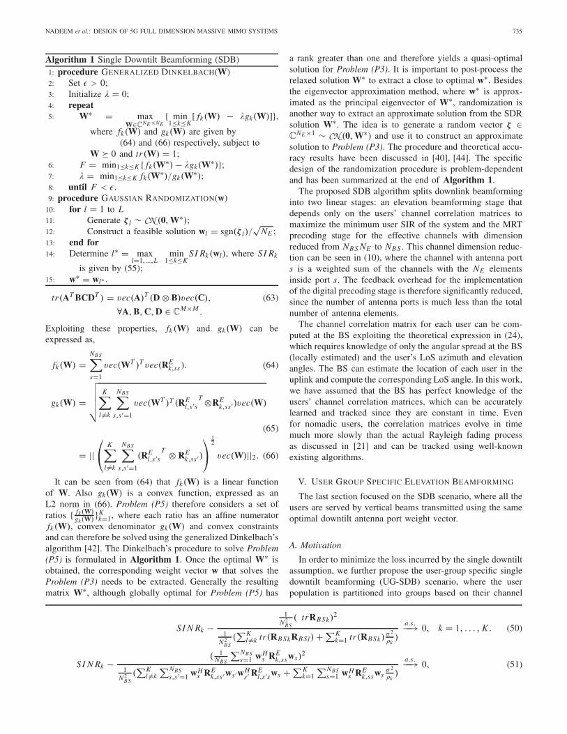
The single-user MISO case is studied first, whereTheorem 2 is used to optimize the weight vectors ws , ofthe s = 1, . . . , NBS antenna ports. The BS equipped with a10 × NBS AAS serves an outdoor user located at the edge ofa cell of radius 250m, with the LoS angle θ0 computed to be95.37o. The user throughput for the optimal downtilt weightvectors is plotted in red in Fig. 5 along with the cases wherethe electrical downtilt angles are set to specific pre-definedvalues with weights computed using (9). It is evident thatchoosing the weight vectors according to Theorem 2 yieldshigher capacity values. Also, the theoretical capacity obtainedusing the deterministic approximation of the SNR in (70)approximates the Monte-Carlo simulated capacity obtainedusing (37) quite well.
B. Performance Comparison of SDB in theMulti-User MISO Setting
In this section, we study the multi-user MISO system withK users placed randomly in a cell of radius 250m, at a
NADEEM et al.: DESIGN OF 5G FULL DIMENSION MASSIVE MIMO SYSTEMS 737
Fig. 5. Performance of a single user MISO system.
minimum distance of 30m from the BS, where NBS > K .Simulations results are used to confirm the performance gainsof the proposed SDB algorithm by comparing it with thefollowing downtilting strategies.
• Cell-specific tilting (CST): The first strategy uses acommon fixed tilt denoted as θt ilt for all antenna portswith MRT precoding in the horizontal domain [26].The downtilt weights corresponding to the tilt angle arecomputed using the 3GPP proposed weight expressiongiven in (9).
• Switched Beam Tilting (SBT): In this tilting strategyproposed in [23], the cell is partitioned into two verticalregions and one of the two (θt ilt , θ3dB) pairs is applied atthe BS when serving each region. The pairs are calculatedas (113.75o, 21o) and (96.51o, 6.5o). The transmissionusing MRT precoding is scheduled to one of the twovertical regions in each time slot. The vertical regionactivity factor for region s is given as |Ks |
K , where Ks
is the set of users in the vertical region s. This strategyis denoted as MRT-SBT.
• Multi-User Active Beamforming (MUAB): In this tilt-ing strategy proposed in [27], the approximate antennaport radiation pattern expression given in [24] is utilized.Under the high SNR approximation, the optimal downtiltangle is computed as the weighted arithmetic mean valueof the elevation LoS angles of all the users. This strategyis studied with MRT precoding and the resulting systemis denoted as MRT-MUAB respectively.
The first result uses a 10 × 40 AAS to compare the SIRperformance of SDB to that of MRT-CST, where the latteris simulated for several values of θt ilt and the correspondingweights are computed using (9). The Monte-Carlo simulatedminimum user SI R is plotted in Fig. 6 along with thedeterministic equivalent in (52). The Gaussian randomizationin Algorithm 1 is implemented using L = 100 and 400 iter-ations. The deterministic equivalent matches the Monte-Carloresult quite well for moderate number of antennas. Moreimportantly, the potential of elevation beamforming in enhanc-ing the system performance is confirmed as the quasi-optimaldowntilt weight vector obtained using the SDB algorithmyields significant performance gains when compared to theexisting implementations with fixed downtilt angles.
Fig. 6. Performance of SDB in a multi-user MISO system.
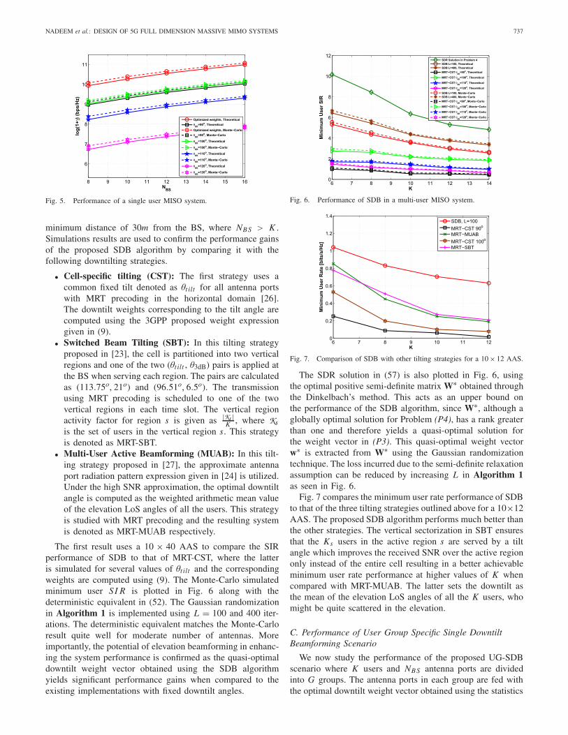
Fig. 7. Comparison of SDB with other tilting strategies for a 10 × 12 AAS.
The SDR solution in (57) is also plotted in Fig. 6, usingthe optimal positive semi-definite matrix W∗ obtained throughthe Dinkelbach’s method. This acts as an upper bound onthe performance of the SDB algorithm, since W∗, although aglobally optimal solution for Problem (P4), has a rank greaterthan one and therefore yields a quasi-optimal solution forthe weight vector in (P3). This quasi-optimal weight vectorw∗ is extracted from W∗ using the Gaussian randomizationtechnique. The loss incurred due to the semi-definite relaxationassumption can be reduced by increasing L in Algorithm 1as seen in Fig. 6.
Fig. 7 compares the minimum user rate performance of SDBto that of the three tilting strategies outlined above for a 10×12AAS. The proposed SDB algorithm performs much better thanthe other strategies. The vertical sectorization in SBT ensuresthat the Ks users in the active region s are served by a tiltangle which improves the received SNR over the active regiononly instead of the entire cell resulting in a better achievableminimum user rate performance at higher values of K whencompared with MRT-MUAB. The latter sets the downtilt asthe mean of the elevation LoS angles of all the K users, whomight be quite scattered in the elevation.
C. Performance of User Group Specific Single DowntiltBeamforming Scenario
We now study the performance of the proposed UG-SDBscenario where K users and NBS antenna ports are dividedinto G groups. The antenna ports in each group are fed withthe optimal downtilt weight vector obtained using the statistics
738 IEEE TRANSACTIONS ON COMMUNICATIONS, VOL. 66, NO. 2, FEBRUARY 2018
Fig. 8. Performance of user-group specific single downtilt beamforming ina multi-user MISO system.
Fig. 9. Effect of the number of user groups on the performance of a multi-user MISO system.
of the users being served in that group. The simulation isdone for NBS = 36, NE = 5 and G = 3. The values forθ0,g , g = 1, . . . , G and � are set as [93o, 101o, 109o] and7.5o respectively. The user grouping is done as explained inAlgorithm 2, where r∗
g = 60 and the optimal weight vector w∗g
for each antenna ports group, comprising of NBS,g = 12 ports,is computed using the SDB Algorithm 1. The result for theminimum user SIR is plotted in Fig. 8, which clearly highlightsthe performance gains that can be achieved by user-grouping.The gap between the curves with and without grouping startsto decrease as K increases, because for higher K , a largernumber of users Kg are served in each group by the sameNBS,g antenna ports per group.
The proposed user-grouping method is compared with K-means clustering, which is a standard iterative algorithmthat partitions the observations into groups such that eachobservation belongs to the group with the nearest mean.Our proposed user-grouping method motivated by the fixedquantization method in [21] performs better than K-means,which is also in accordance with the observation of the authorsin [21].
In the next figure, we study the effect of increasing thenumber of user groups. The results are plotted for G = 2, 3, 4and 5 in Fig. 9, where θ0,g , g = 1, . . . , G and � are selected,ensuring that the resulting angular supports are disjoint.A 5×60 AAS is utilized for K = 30 users. The quasi-optimalweight vector w∗
g , for antenna ports group g serving user groupg is computed following the steps in Algorithm 2. As the
number of groups increases upto four, the SIR performanceimproves since every user group is now served with an optimaldowntilt weight vector determined using the spatial statisticsof only the users in that group. A higher number of groupsrealizes a higher degree of vertical separation of the usersthrough the design of a higher number of elevation domainbeams, where each beam serves a small number of co-locatedusers. However, depending on the positions of the users in thecell, it becomes more and more likely to have Kg > NBSg inone of the groups as G increases, requiring user scheduling inthat group, while the overall number of users K < NBS . As theratio of Kg to NBSg becomes high in group g, the minimumSIR under grouping starts to deteriorate as compared to thatwith a lower number of groups.
These founding results provide a flavor of the performancegains realizable through FD-MIMO techniques. More sophis-ticated 3D beamforming methods can be devised in the futurethat allow every port to transmit at a different optimal downtiltangle. In fact, for NBS >> K , spatially separated beamsto almost all the users can be realized, which is why FDbeamforming can be highly advantageous when amalgamatedwith massive MIMO techniques.
VII. CONCLUSION
This paper reviewed the recent development of FD-MIMOtechnology for evolution towards 5G cellular systems andstudied the architecture of the 2D active antenna arrays utilizedby these systems. The 2D AAS not only serves as a practicalimplementation of massive MIMO systems, but also has thepotential to boost spectral efficiency by providing the abilityof adaptive electronic beam control in both the elevation andazimuth dimensions. The SCF for the channels constitutedby individual antenna elements in the AAS was derivedand used to compute the correlation between the overallantenna ports for any arbitrary 3D propagation environment.The performance benefits of FD-MIMO techniques were thenstudied by devising elevation beamforming algorithms, thatoptimize the downtilt antenna port weight vectors in the singleuser and multi-user MISO settings, utilizing the quasi-staticchannel correlation matrices of the users obtained from thederived SCF. The problem of determining the downtilt weightvector that maximizes the minimum SIR of the multi-userMISO system was formulated under the assumption that allports serve using the same optimal downtilt weight vector,and solved using SDR and Dinkelbach’s method. Finally,the user-group specific single downtilt beamforming scenariowas devised. Simulation results confirmed the potential ofFD-MIMO techniques to improve the system performance.
APPENDIX APROOF OF THEOREM 2
This theorem follows from expressing tr(hhH ) as aquadratic term in z using (32) to re-write the SNR in (37)as follows,
γ = �
σ 2n
hH h = �
σ 2n
zH R12
H
BS R12BSz. (67)
Next exploiting Lemma 2 and the fact that the covariancematrix RBS defined in (29) is Hermitian, positive semi-definite
NADEEM et al.: DESIGN OF 5G FULL DIMENSION MASSIVE MIMO SYSTEMS 739
1
NBSSI N Rk − ( 1
NBStr(RBSk))
2
∑Kl �=k
1NBS
tr(RBSkhlhHl ) + σ 2
∑Kk=1
1NBS
tr(RBSk)
�k
a.s.−−→ 0. (75)
SI N Rk − ( 1NBS
tr(RBSk))2
1N2
BS(∑K
l �=k tr(RBS
12l
H
RBSkRBS
12l ) + σ 2
∑Kk=1 tr(RBSk)
�k)
a.s.−−→ 0. (76)
and satisfies the condition in Assumption A-1 we have,
1
NBSzH RBSz − 1
NBStr(RBS)
a.s.−−→ 0. (68)
where, tr(RBS) =NBS∑s=1
wsH RE
ssws , (69)
and REss is a NE × NE matrix given by RE ([(s − 1)NE + 1 :
s NE ], [(s − 1)NE + 1 : s NE ]), where RE is defined in (31).Therefore in the large (NBS, NE ) regime,
1
NBSγ − �
NBSσ 2n
NBS∑s=1
wsH RE
sswsa.s.−−→ 0. (70)
Consequently, in the large (NBS , NE ) regime, the optimizationproblem (P1) can be written as,
maximizew1,w2,...,wNBS
NBS∑s=1
wsH RE
ssws (71)
subject to ||ws ||2 = 1, for s = 1, . . . , NBS . (72)
Problem (P1) is equivalent to finding the optimal w∗s =
argw
max||w||2=1||RE
ss
12 w||22, s = 1, . . . , NBS , which has the simple
eigenvector solution stated in Theorem 2.
APPENDIX BPROOF OF PROPOSITION 1
In order to prove Proposition 1, the following theorem willbe required.
Theorem 3. Continuous Mapping Theorem [45]. Let {Xn}be a sequence of N-dimensional random vectors. Let g :R
N → RL be a continuous function. Then,
Xna.s.−−→ X �⇒ g(Xn)
a.s.−−→ g(X), (73)
wherea.s.−−→ denotes almost sure convergence.
To prove Proposition 1, note that the channel vector
for user k, hk is given by RBS
12k zk , where the condition
described in Assumption A-1 on the Hermitian, positive semi-definite channel correlation matrices RBSk holds for all users,k = 1, . . . , K . With this, (49) can be written as,
SI N Rk = |zHk RBSkzk |2∑K
l �=k zHk RBS
12k
H
hl hHl RBS
12k zk+ σ2∑K
k=1 zHk RBS k zk
�k
. (74)
Applying Lemma 2 along with the continuous mappingtheorem on the numerator and Lemma 2 along with the factthat if A ∈ C
M×N and B ∈ CN×M , then tr(AB) = tr(BA) on
the denominator would yield the convergence result for (74)as shown in (75), at the top of this page.
Substituting the expression for hl as RBS
12l zl and applying
the convergence theorem in Lemma 2 a second time on thedenominator would yield (76), as shown at the top of this page.Again using tr(AB) = tr(BA), would complete the proof ofProposition 1.
REFERENCES
[1] E. Dahlman, S. Parkvall, J. Sköld, and P. Beming, 3G Evolution:HSPA and LTE for Mobile Broadband, 2nd ed. San Diego, CA, USA:Academic, 2008.
[2] F. Rusek et al., “Scaling up MIMO: Opportunities and challenges withvery large arrays,” IEEE Signal Process. Mag., vol. 30, no. 1, pp. 40–60,Jan. 2013.
[3] T. L. Marzetta, “Noncooperative cellular wireless with unlimited num-bers of base station antennas,” IEEE Trans. Wireless Commun., vol. 9,no. 11, pp. 3590–3600, Nov. 2010.
[4] L. Lu, G. Y. Li, A. L. Swindlehurst, A. Ashikhmin, and R. Zhang,“An overview of massive MIMO: Benefits and challenges,” IEEE J. Sel.Topics Signal Process., vol. 8, no. 5, pp. 742–758, Oct. 2014.
[5] Y.-H. Nam et al., “Full-dimension MIMO (FD-MIMO) for next gen-eration cellular technology,” IEEE Commun. Mag., vol. 51, no. 6,pp. 172–179, Jun. 2013.
[6] Study on 3D Channel Model for LTE, document 3GPP TR 36.873V12.0.0, Sep. 2014.
[7] Study of Radio Frequency (RF) and Electromagnetic Compatibility(EMC) Requirements for Active Antenna Array System (AAS) BaseStation, document 3GPP TR 37.840 V12.0.0, Mar. 2013.
[8] K. Linehan and R. Chandrasekaran, “Active antennas: The next step inradio and antenna evolution,” CommScope, Hickory, NC, USA, WhitePaper WP-105435, 2011. [Online]. Available: https://www.yumpu.com/en/document/view/8991085/active-antennas-the-next-step-in-radio-and-antenna-evolution
[9] Huawei. (Nov. 2012). Active Antenna System: Utilizing the Full Poten-tial of Radio Sources in the Spatial Domain. [Online]. Available:http://www1.huawei.com/en/static/AAS-129092-1-197969.pdf
[10] Study on 3D-Channel Model for Elevation Beamforming and FD-MIMOStudies for LTE, document R1-122034, 3GPP TSG RAN Plenary 58,Barcelona, Spain, Dec. 2012.
[11] Study on Elevation Beamforming/Full-Dimension (FD) MIMO for LTE,document 3GPP TR 36.897 V13.0.0, Jun. 2015.
[12] B. Debaillie et al., “Analog/RF solutions enabling compact full-duplexradios,” IEEE J. Sel. Areas Commun., vol. 32, no. 9, pp. 1662–1673,Sep. 2014.
[13] Y. Song, X. Yun, S. Nagata, and L. Chen, “Investigation on elevationbeamforming for future LTE-advanced,” in Proc. IEEE Int. Conf. Com-mun. Workshops (ICC), Jun. 2013, pp. 106–110.
[14] A. Kammoun, H. Khanfir, Z. Altman, M. Debbah, and M. Kamoun,“Preliminary results on 3D channel modeling: From theory to standard-ization,” IEEE J. Sel. Areas Commun., vol. 32, no. 6, pp. 1219–1229,Jun. 2014.
[15] W. Lee, S.-R. Lee, H.-B. Kong, and I. Lee, “3D beamforming designsfor single user MISO systems,” in Proc. IEEE Global Commun.Conf. (GLOBECOM), Dec. 2013, pp. 3914–3919.
[16] Y. Kim et al., “Full dimension MIMO (FD-MIMO): The next evolutionof MIMO in LTE systems,” IEEE Wireless Commun., vol. 21, no. 2,pp. 26–33, Apr. 2014.
[17] J. Koppenborg, H. Halbauer, S. Saur, and C. Hoek, “3D beamformingtrials with an active antenna array,” in Proc. ITG Workshop SmartAntennas, 2012, pp. 110–114.
[18] F. Sohrabi and W. Yu, “Hybrid digital and analog beamforming designfor large-scale antenna arrays,” IEEE J. Sel. Topics Signal Process.,vol. 10, no. 3, pp. 501–513, Apr. 2016.
740 IEEE TRANSACTIONS ON COMMUNICATIONS, VOL. 66, NO. 2, FEBRUARY 2018
[19] R. Rajashekar and L. Hanzo, “Hybrid beamforming in mm-wave MIMOsystems having a finite input alphabet,” IEEE Trans. Commun., vol. 64,no. 8, pp. 3337–3349, Aug. 2016.
[20] J. Choi, “Beam selection in mm-wave multiuser MIMO systemsusing compressive sensing,” IEEE Trans. Commun., vol. 63, no. 8,pp. 2936–2947, Aug. 2015.
[21] J. Nam, A. Adhikary, J.-Y. Ahn, and G. Caire, “Joint spatial division andmultiplexing: Opportunistic beamforming, user grouping and simplifieddownlink scheduling,” IEEE J. Sel. Topics Signal Process., vol. 8, no. 5,pp. 876–890, Oct. 2014.
[22] S. Saur and H. Halbauer, “Exploring the vertical dimension of dynamicbeam steering,” in Proc. 8th Int. Workshop Multi-Carrier Syst. Solutions(MC-SS), May 2011, pp. 1–5.
[23] N. Seifi, M. Coldrey, and T. Svensson, “Throughput optimization inMU-MIMO systems via exploiting BS antenna tilt,” in Proc. IEEEGlobal Commun. Conf. (GLOBECOM) Workshops, 2012, pp. 653–657.
[24] Guidelines for Evaluation of Radio Interface Technologies for IMT-Advanced, document ITU-R M.2135-1, Radiocommunication Sector ofInternational Telecommunication Union, 2009.
[25] Further Advancements for E-UTRA Physical Layer Aspects (Release 9),document 3GPP TR 36.814 V9.0.0, Mar. 2010.
[26] N. Seifi, J. Zhang, R. W. Heath, Jr., T. Svensson, and M. Coldrey,“Coordinated 3D beamforming for interference management in cel-lular networks,” IEEE Trans. Wireless Commun., vol. 13, no. 10,pp. 5396–5410, Oct. 2014.
[27] W. Lee, S.-R. Lee, H.-B. Kong, S. Lee, and I. Lee, “Downlink verticalbeamforming designs for active antenna systems,” IEEE Trans. Com-mun., vol. 62, no. 6, pp. 1897–1907, Jun. 2014.
[28] A. M. Tulino, A. Lozano, and S. Verdú, “Impact of antenna correlationon the capacity of multiantenna channels,” IEEE Trans. Inf. Theory,vol. 51, no. 7, pp. 2491–2509, Jul. 2005.
[29] S. K. Yong and J. S. Thompson, “Three-dimensional spatial fadingcorrelation models for compact MIMO receivers,” IEEE Trans. WirelessCommun., vol. 4, no. 6, pp. 2856–2869, Nov. 2005.
[30] M. Shafi et al., “Polarized MIMO channels in 3-D: Models, measure-ments and mutual information,” IEEE J. Sel. Areas Commun., vol. 24,no. 3, pp. 514–527, Mar. 2006.
[31] K. Mammasis, R. W. Stewart, and J. S. Thompson, “Spatial fadingcorrelation model using mixtures of Von Mises Fisher distributions,”IEEE Trans. Wireless Commun., vol. 8, no. 4, pp. 2046–2055, Apr. 2009.
[32] P. D. Teal, T. D. Abhayapala, and R. A. Kennedy, “Spatial correlationfor general distributions of scatterers,” IEEE Signal Process. Lett., vol. 9,no. 10, pp. 305–308, Oct. 2002.
[33] Q.-U.-A. Nadeem, A. Kammoun, M. Debbah, and M.-S. Alouini, “Ageneralized spatial correlation model for 3D MIMO channels basedon the Fourier coefficients of power spectrums,” IEEE Trans. SignalProcess., vol. 63, no. 14, pp. 3671–3686, Jul. 2015.
[34] D. J. Hofsommer and M. L. Potters, “Table of Fourier coeffi-cients of associated Legendre functions,” Comput. Dep. Math. Center,Amsterdam, The Netherlands, Tech. Rep. 478, Jun. 1960.
[35] Q.-U.-A. Nadeem, A. Kammoun, M. Debbah, and M.-S. Alouini, “Spa-tial correlation characterization of a full dimension massive MIMO sys-tem,” in Proc. IEEE Global Commun. Conf. (GLOBECOM), Dec. 2016,pp. 1–7.
[36] M. R. McKay and I. B. Collings, “On the capacity of frequency-flat and frequency-selective Rician MIMO channels with single-ended correlation,” IEEE Trans. Wireless Commun., vol. 5, no. 8,pp. 2038–2043, Aug. 2006.
[37] B. Partov, D. J. Leith, and R. Razavi, “Utility fair optimization ofantenna tilt angles in LTE networks,” IEEE/ACM Trans. Netw., vol. 23,no. 1, pp. 175–185, Feb. 2015.
[38] R. Couillet and M. Debbah, Random Matrix Methods for WirelessCommunications, 1st ed. New York, NY, USA: Cambridge Univ. Press,2011.
[39] T. K. Y. Lo, “Maximum ratio transmission,” IEEE Trans. Commun.,vol. 47, no. 10, pp. 1458–1461, Oct. 1999.
[40] E. Karipidis, N. D. Sidiropoulos, and Z.-Q. Luo, “Quality of serviceand max-min fair transmit beamforming to multiple cochannel multicastgroups,” IEEE Trans. Signal Process., vol. 56, no. 3, pp. 1268–1279,Mar. 2008.
[41] A. Zappone and E. Jorswieck, “Energy efficiency in wireless networksvia fractional programming theory,” Found. Trends Commun. Inf. Theory,vol. 11, nos. 3–4, pp. 185–396, 2015.
[42] A. Zappone, L. Sanguinetti, G. Bacci, E. Jorswieck, and M. Debbah,“Energy-efficient power control: A look at 5G wireless technologies,”IEEE Trans. Signal Process., vol. 64, no. 7, pp. 1668–1683, Apr. 2016.
[43] K. Schäcke, “On the Kronecker product,” M.S. thesis, Dept. Math., Univ.Waterloo, Waterloo, ON, Canada, 2004.
[44] Z.-Q. Luo, W.-K. Ma, A. M.-C. So, Y. Ye, and S. Zhang, “Semidefiniterelaxation of quadratic optimization problems,” IEEE Signal Process.Mag., vol. 27, no. 3, pp. 20–34, May 2010.
[45] J. Shao, Mathematical Statistics. New York, NY, USA: Springer, 2007.
Qurrat-Ul-Ain Nadeem (S’15) was born inLahore, Pakistan. She received the B.S. degree inelectrical engineering from the Lahore Universityof Management Sciences, Pakistan, in 2013, andthe M.S. degree in electrical engineering fromthe King Abdullah University of Science andTechnology, Thuwal, Saudi Arabia, in 2015, whereshe is currently pursuing the Ph.D. degree with theElectrical Engineering Department. Her researchinterests include channel modeling, antenna arraydesign and performance analysis of wireless
communication systems.
Abla Kammoun (M’10) was born in Sfax, Tunisia. She received theEngineering degree in signal and systems from the Tunisia Polytechnic School,La Marsa, and the master’s and Ph.D. degrees in digital communicationsfrom Telecom Paris Tech. From 2010 to 2012, she was a Post-DoctoralResearcher with the TSI Department, Telecom Paris Tech. She was thenwith the Alcatel-Lucent Chair on Flexible Radio, Suplec, until 2013. She iscurrently a Research Scientist with the King Abdullah University of Scienceand Technology. Her research interests include performance analysis, randommatrix theory, and semi-blind channel estimation.
Mérouane Debbah (S’01–AM’03–M’04–SM’08–F’15) received the M.Sc. and Ph.D. degrees fromthe Ecole Normale Suprieure de Cachan, France.He was with Motorola Labs, Saclay, France, from1999 to 2002, and the Vienna Research Center forTelecommunications, Vienna, Austria, until 2003.From 2003 to 2007, he was with the Mobile Com-munications Department, Institut Eurecom, SophiaAntipolis, France, as an Assistant Professor. Since2007, he has been a Full Professor with CentraleSu-pelec, Gif-sur-Yvette, France. From 2007 to 2014,
he was the Director of the Alcatel-Lucent Chair on Flexible Radio. Since2014, he has been the Vice-President of the Huawei France R&D Center andthe Director of the Mathematical and Algorithmic Sciences Laboratory. Hisresearch interests lie in fundamental mathematics, algorithms, statistics, andinformation and communication sciences research. He is a WWRF Fellowand a member of the academic senate of Paris–Saclay. He was a recipient ofthe ERC grant MORE (Advanced Mathematical Tools for Complex NetworkEngineering). He received 17 best paper awards, among which the 2007 IEEEGLOBECOM Best Paper Award, the Wi-Opt 2009 Best Paper Award, the2010 Newcom++ Best Paper Award, the WUN CogCom Best Paper 2012and 2013 Award, the 2014 WCNC Best Paper Award, the 2015 ICC BestPaper Award, the 2015 IEEE Communications Society Leonard G. AbrahamPrize, the 2015 IEEE Communications Society Fred W. Ellersick Prize, the2016 IEEE Communications Society Best Tutorial Paper Award, the 2016European Wireless Best Paper Award, the 2017 EURASIP Best Paper Award,and the Valuetools 2007, Valuetools 2008, CrownCom2009, Valuetools 2012,and SAM 2014 best student paper awards. He was a recipient of the MarioBoella Award in 2005, the IEEE Glavieux Prize Award in 2011, and theQualcomm Innovation Prize Award in 2012. He is an Associate Editor inChief of the journal Random Matrix: Theory and Applications. He was anAssociate and Senior Area Editor of the IEEE TRANSACTIONS ON SIGNAL
PROCESSING from 2011 to 2013 and 2013 to 2014, respectively.
Mohamed-Slim Alouini (S’94–M’98–SM’03–F’09)was born in Tunis, Tunisia. He received the Ph.D.degree in electrical engineering from the CaliforniaInstitute of Technology, Pasadena, CA, USA, in1998. He served as a Faculty Member with theUniversity of Minnesota, Minneapolis, MN, USA,then Texas A&M University at Qatar, Doha, Qatar,before joining King Abdullah University of Scienceand Technology, Thuwal, Saudi Arabia, as a Pro-fessor of electrical engineering in 2009. His currentresearch interests include the modeling, design, and
performance analysis of wireless communication systems.