38
1 ECE692 Topic Presentation Power/thermal-Aware Utilization Control Xing Fu 22 September 2009
| Date post: | 03-Jan-2016 |
| Category: |
Documents |
| Upload: | melina-morton |
| View: | 214 times |
| Download: | 1 times |

1
ECE692 Topic Presentation
Power/thermal-Aware Utilization Control
Xing Fu22 September 2009

2
Outline of the Presentation
• Why consider power/thermal in real-time systems?• Conflicts between power/thermal management and real-time
guarantee.• For example, the CPU frequency reduction the tasks’
execution times will increase.
• Related work• The Limitations.
• Motivation of papers to present• 1st: meet all the deadlines despite runtime exec time variations
and save power.• 2nd: guarantees both thermal and timeliness.

3
Power-Aware CPU Utilization Control
for Distributed Real-Time Systems Xiaorui Wang, Xing Fu, Xue Liu*, Zonghua Gu$
University of Tennessee, Knoxville*McGill University
$Hong Kong Univ. of Sci. and Tech.

4
Recap of Utilization Control• CPU utilization: a trade-off
– Too high system overload possible crash• OS frozen by higher-priority real-time threads
– Too low poor application QoS, excessive power consumption
• Schedulable utilization bound– Utilization ≤ bound meet all deadlines– Highest possible utilization with deadline guarantee
• Uncertainties– Unpredictable exec times (e.g. influenced by sensor data)– External resource contention (e.g. Denial of Service attacks)
Must maintain desired utilization under uncertainty!
University of Tennessee, Knoxville
5
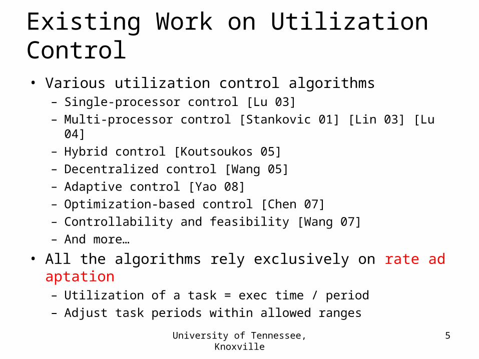
Existing Work on Utilization Control• Various utilization control algorithms
– Single-processor control [Lu 03]– Multi-processor control [Stankovic 01] [Lin 03] [Lu 04]– Hybrid control [Koutsoukos 05]– Decentralized control [Wang 05]– Adaptive control [Yao 08]– Optimization-based control [Chen 07]– Controllability and feasibility [Wang 07]– And more…
• All the algorithms rely exclusively on rate adaptation– Utilization of a task = exec time / period– Adjust task periods within allowed ranges
University of Tennessee, Knoxville

6
Limitations of Rate Adaptation
1. Often infeasible to achieve utilization set points– WCET configuration underutilization even at highest rates– Under-utilized processors excessive power consumption
• Can save power by frequency scaling
2. Estimated rate ranges may not be accurate– Unexpected rate saturation feasibility
3. Task rates cannot be adapted in some DRE systems– Need another knob for utilization control
University of Tennessee, Knoxville

7
Power-Aware CPU Utilization Control• Util control by rate adaptation + CPU frequency scaling
– Utilization of a task = exec time / period
• Control approach– Controlled variable: utilizations of all the processors in a DRE– Manipulated variable: task rates and DVFS level– Variations: inaccurate or varying task exec times
T1
T2
T3
T11 T12 T13
P1P2 P3
Precedence Constraints
Subtask
University of Tennessee, Knoxville

8
Recap of End-to-End Task Modelin Distributed Real-Time Systems
• Periodic task Ti = a chain of subtasks {Tij} on diff procs– All subtasks run at the same rate– End-to-end deadline = sum of all sub-deadlines
• Task rate can be adjusted within a range– Higher rate better performance
• CPU frequency can be adjusted within a range– Lower frequency power savings
T1
T2
T3
T11 T12 T13
P1P2 P3
Precedence Constraints
Subtask
University of Tennessee, Knoxville

9
Control Problem Formulation• Control objective:
subject to two constraints
1. task rates: Rmin,j rj(k) Rmax,j (1 ≤ j ≤ m)
2. CPU frequency: Fmin,i fi(k) Fmax,i (1 ≤ i ≤ n)
T1
T2
T3
T11 T12 T13
P1P2 P3
Precedence Constraints
Subtask
n
iii
mjkrkuB
j 1
2
}1)|({))((min
University of Tennessee, Knoxville

10
System Model without Freq Scaling
• New utilization = old utilization + change• Utilization change = actual exec time × task rate change
• cjl: estimated execution time of Tjl
• gi = actual execution time / estimation
– Models uncertainty in execution times
u1(k) = u1(k-1) + g1c11r1(k-1)u2(k) = u2(k-1) + g2c12r1(k-1)
T1
P1 P2
T11 T12
System model:
University of Tennessee, Knoxville

11
System Model with Freq Scaling
• Utilization change = actual exec time × task rate change• actual exec time = exec time / relative CPU frequency
T1
P1 P2
T11 T12
New system model:
System model is now nonlinear for a single control loop Solution: separate to two control loops
Each loop assumes that the other control input is constant
)1(
)1(
)(
)(
1
1
1
1
kf
kr
kf
krcg 1)-(ku (k)u 11111
)1(
)1(
)(
)(
2
1
2
1
kf
kr
kf
krcg 1)-(ku (k)u 12222
University of Tennessee, Knoxville

12
Two-Layer Control Architecture Two coordinated control loops
Cluster-level task rate adaptation loop (EUCON) One CPU frequency scaling loop on each processor Two loops run on different timescales: rate loop runs much faster
ModelPredictiveController
Distributed Real-Time System(m tasks, n processors)
UtilizationMonitor
RateModulator RM
UM UM
RM
ProportionalController
FrequencyModulator
PC
FM
PC
FM
…P1 P2 Pn
ModelPredictiveController
University of Tennessee, Knoxville
ProportionalController

13
CPU Frequency Scaling Loop
• System model of processor P1 by assuming rj(k) = rj
• Controller design– g1 is unknown and assumed to be 1 (exec times are accurate)
– A proportional (P) controller can achieve stability and accuracy
• Stability analysis for model variations– When g1 is not 1, (exec times vary at runtime)
– Result: 0 < g1 < 2
• Actual exec times cannot be twice their estimated values
• Need to be pessimistic for exec time estimation
)1()( 1
1
1
1
kf
r
kf
rcg 1)-(ku (k)u 11111
University of Tennessee, Knoxville

14
Coordination Analysis
• Goal: Coordinate the two control loops for global stability• Stability of rate loop under the impact of the freq loop
– Result: relative CPU frequency cannot be less than 0.1– Most real processors have DVFS range from 1 to 0.5 (roughly)
• Control period configuration– Period of the frequency loop > settling time of the rate loop– Period of the rate loop = 2 sec
• Determined based on task periods
– Settling time of the rate loop = 5 periods– Period of the frequency loop = 20 sec > 10 sec
University of Tennessee, Knoxville

15
System Implementation• Implemented based on FC-ORB real-time middleware• Test-bed
– 12 tasks (25 subtasks) on 4 AMD 3800+ processor (5 freq levels)– openSUSE Linux 11 with real-time support– RMS (Rate Monotonic Scheduling) with release guard
• Controllers– Rate controller: running on a separate machine– Frequency P controller: running on each processor
• CPU frequency modulator– 5 discrete freq levels to approximate the desired continuous level?
• For 3.2, use 3, 3, 3, 3, 4 on a smaller timescale (subintervals)
University of Tennessee, Knoxville

16
Empirical Results for Freq Scaling Loop
• No rate adaptation• Utilization set point is
RMS bound• Exec time increase fr
om 600s to 1200s• Freq scaling can be u
sed for util control and power savings
• More results are in the paper
University of Tennessee, Knoxville

17
Frequency Scaling vs. EUCON
EUCON fails due to rate saturation
EUCON leads to power waste
Freq scaling achieves the set points
Freq scaling achieves power savings
Freq scaling loop is
activated here
University of Tennessee, Knoxville

18
Coordinated Utilization Control
Rate adaptation alone fails Freq scaling alone fails
Coordinated control achieves the set points
Coordinated control also achieves power savings
University of Tennessee, Knoxville

19
Conclusions
• Existing work on utilization control relies exclusively on rate adaptation, which has some limitations
• This paper– Formulates a new utilization control problem by
rate adaptation + CPU frequency scaling for power saving– Proposes a two-layer control architecture – Provides coordination analysis– Presents empirical results to demonstrate the effectiveness
University of Tennessee, Knoxville

20
Dynamic Thermal and Timeliness Guarantees for Distributed Real-Time
Embedded Systems
Department of EECSUniversity of Tennessee, Knoxville
Xing Fu, Xiaorui Wang, and Eric Puster

21
Introduction • Distributed Real-Time Embedded Systems
• Examples: Mission critical systems and Cyber physical system
• Requirements• guarantee timeliness• guarantee thermal
• 50% of all electronics failures are related to overheating• the lifetime of a processor can be approximately halved if
its temperature is increased 10-15℃。• 15 increase in temperature could double the failure rat℃
e of a disk drive• Temperature must be explicitly controlled for reliability.• An Integrated solution

22
Integrated solution
• Util control by rate adaptation • Utilization of a task = exec time / period
• Thermal control by CPU frequency scaling• CPU frequency Power Temperature
System Diagram
Processor N
FMTM
Cluster Level Utilization Controller
TC
UM RM
FMTMTC
UM RMRate Modulator
Utilization Monitor
Thermal Controller
Thermal Monitor
Frequency Modulator
Processor 1 Processor 2
23
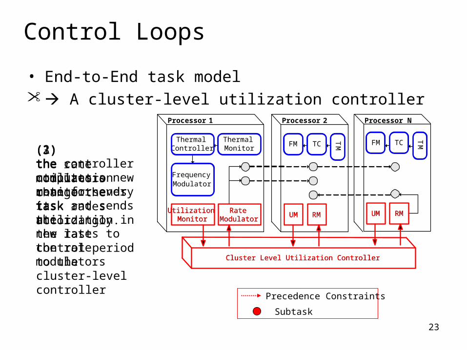
Control Loops
• End-to-End task model A cluster-level utilization controller
Precedence Constraints
Subtask
(2) the controllercomputes a new rate for every task and sends thenew rates to the rate modulators
(1) the utilization monitor sends its utilization in the last control period to the cluster-level controller
(3) the rate modulatorschange the task rates accordingly.
Processor N
FM
TM
Cluster Level Utilization Controller
TC
UM RM
FM
TMTC
UM RMRate Modulator
Utilization Monitor
Thermal Controller
Thermal Monitor
Frequency Modulator
Processor 1 Processor 2
UM UMUtilization Monitor
Cluster Level Utilization Controller
RM RMRate Modulator

24
Thermal Control Loop
Processor
CPU frequency TemperatureThermal
Controller
Temperature set point
55 ℃50 ℃
Error: -5℃ Decrease
Workload variation
50℃
• PID (Proportional-Integral-Differential) controller• System modeling• Controller design• Performance analysis

25
System model
• We use two steps to model the relationship between ti(k) and fi(k)
• Power model relates fi(k) to Pi(k).
• Thermal model relates Pi(k) to ti(k).
• System model
( ) (2 ) ( 1) (1 ) ( 2) ( 1)s s s
i i i i ii i i i i
T T Tt k t k t k A d k
R C R C C
ST
iR
iC
Sampling period of sensors
Thermal resistance
Thermal capacity
( ) ( ) ( 1)i i id k f k f k 1 100 200 300 400 500
30
34
38
42
46
50
Time (sec)
Tem
per
atu
re (
Cel
siu
s)
measurement
Model

26
Controller Design & Performance
Processor
TemperatureTemperature set point )(ke
• PID controller
( )pK e k( ) ( 1) ( )i i pf k f k K e k
• Control performance
(e.g. Stability, Zero steady state error)
• If the temp cannot reach the temp set point even when frequency is the highest, the controller is saturated and the system has highest performance.

27
Coordination
• Goal: coordinate the two control loops for global stability
• Global stability: both the two control loops are still stable under the impact from the other loop.
•Robust Control : Small gain theorem
• Example: Utilization control loop
• Results: global stable under our hardware configuration and workload.
Set pointController
System controlled
Uncertainty

28
Thermal controller
Thermal controller
Thermal controller
Thermal controller
System Implementation
• Our solution is evaluated on a hardware test-bed while most existing work uses simulations.
• Implemented based on FC-ORB real-time middleware• Test-bed
• 12 tasks (25 subtasks) on 4 AMD 3800+ processor (5 freq levels)• OpenSUSE Linux 11 with real-time support• RMS (Rate Monotonic Scheduling) with release guard
• Controllers
Utilization controller

29
Key components
• Temperature sensors• Open source software.• Thermometer Machine Specific Register File System• The measured temperature is the maximum temperature of the
processor.

30
Baselines
• OPEN• A typical open-loop solution that configures the task rates and
processor DVFS levels in a static way.
• Ad Hoc• When the current processor temperature is lower than the set
point, Ad Hoc will increase the processor’s DVFS level by one. • When the temperature is lower than the set point, Ad Hoc sets
the DVFS level to the lowest one to avoid overheating.

31
Empirical Results
• Thermal controller
1 200 400 600 800 1000 120025
30
35
40
45
50
55
Time (sec)
Tem
per
atu
re (
°C)
Measurement
Set point
20
25
30
35
40
45
50
41 42 43 44 45
Set Point
Tem
per
atu
reSet pointThermal ControllerAd Hoc
1 200 400 600 800 1000 120025
30
35
40
45
50
55
Time (sec)
Tem
per
atu
re (
°C)
Measurement
Set point
• No utilization control • Temperature set point decreases from 400s to 800s.
• Our solution achieves better performance.

32
Empirical Results
• Thermal variations
1 200 400 600 800 1000 1200 1400 160020
30
40
50
60
Time (sec)
Tem
per
atu
re (
°C)
RTES1
RTES3
RTES2
RTES4
1 200 400 600 800 1000 1200 1400 16000
0.2
0.4
0.6
0.8
1
Time (sec)
CP
U u
tiliz
atio
n
RTES1
RTES3
RTES2
RTES4
1 200 400 600 800 1000 1200 1400 160020
30
40
50
60
Time (sec)
Tem
per
atu
re (
°C)
RTES1
RTES3
RTES2
RTES4
1 200 400 600 800 1000 1200 1400 16000
0.2
0.4
0.6
0.8
1
Time (sec)
CP
U u
tiliz
atio
n
RTES1
RTES3
RTES2
RTES4
Temp set point of a single processor is lowered due to thermal emergency.
Temp set point of all single processors are lowered due to thermal emergency.
Utilization is guaranteed in spite of thermal controller
Utilization is guaranteed in spite of thermal controller

33
Empirical Results
• Task execution time variations
1 200 400 600 800 1000 12000
0.2
0.4
0.6
0.8
1
Time (sec)
CP
U u
tiliz
atio
n
RTES1RTES3
RTES2
RTES4
1 200 400 600 800 1000 12000
0.2
0.4
0.6
0.8
1
Time (sec)
CP
U u
tiliz
atio
n
RTES1
RTES3
RTES2
RTES4
1 200 400 600 800 1000 120025
30
35
40
45
50
55
Time (sec)
Tem
per
atu
re (
°C)
OPEN
Coordinated solution
Set point
• Control based solution guarantees both timeliness and thermal.
• OPEN may violate both utilization and thermal bound.

34
Conclusions
• Existing work studies utilization control and thermal guarantee separately which has some limitations.
• This paper • Proposes an integrated solution problem by
utilization control + thermal control for reliability.• Designs a thermal control loop.• Provides coordination analysis by Robust Control.• Presents empirical results to demonstrate the
effectiveness.

35
Comparison of two papers
Paper 1 Paper 2
What about Power-aware utilization control
Simultaneous utilization and thermal control
Focus CPU frequency scaling loop
Thermal control loop
Key idea CPU frequency can be manipulated to change execution time
Integrate conflicting control loop based on robust control theory

36
Critiques for Paper 1
• DVFS, the only knob to adjust power?• Memory hierarchy and I/O?• Overhead of the frequency transition
• Alternative ways to create a continuous frequency
• Options to convert nonlinear system model • Nonlinear controller• Controllability and feasibility issues• Underutilized real-time systems (courtesy of Klairul)

37
Critiques for Paper 2• Nearly all existing thermal management utilize DVFS as
power management.• Disadvantage• Fan control. Pulse Width Modulation (PWM).
• The assumption of temperature model • multi-core architecture
• Presentation of robust control theory• Possible solution: learn from [1] to present the technical.
• Current way (introducing a ratio) to model uncertainty can be extended.
[1] Task Scheduling for Control Oriented Requirements for Cyber-Physical Systems, RTSS 2008, from Georgia Institute of Technology

38


