Page 1
Work supported in part by US Department of Energy contract DE-AC02-76SF00515
1
Effects of molecular interface modification in hybrid organic-inorganic photovoltaic
cells
a)
94305
ABSTRACT
We have systematically investigated the effects of surface modification of titania
(TiO2) in hybrid TiO2/regioregular poly(3-hexylthiophene) (P3HT) photovoltaic cells.
By employing a series of para-substituted benzoic acids with varying dipoles and a series
of multiply-substituted benzene carboxylic acids, the energy offset at the TiO2/polymer
interface and thus the open circuit voltage of devices can be tuned systematically by 0.25
V. Transient photovoltage measurements showed that the recombination kinetics were
dominated by charge carrier concentration in these devices and were closely associated
with the dark current. The saturated photocurrent of TiO2/P3HT devices exhibits more
than a two-fold enhancement when molecular modifiers with large electron affinity were
employed. The ability of modifiers to accept charge from polymers, as revealed in
photoluminescence quenching measurement with blends of polymers, was shown to be
correlated to the enhancement in device photocurrent. A planar geometry
photoluminescence quenching measurement showed that TiO2 substrates modified by
these same molecules that accept charge quenched more excitons in regioregular P3HT
than bare TiO2 surfaces. An exciton diffusion length in P3HT as large as 6.5 – 8.5 nm
July 2007
Department of Materials Science & Engineering, Stanford University, Stanford, CA
Chiatzun Goh, Shawn R. Scully and Michael D. McGehee
Submitted to Journal of Applied Physics
SLAC, Stanford University, Stanford, CA 94025
SLAC-PUB-12695
Page 2
2
was extracted. By measuring the external quantum efficiency (EQE) of working devices,
it was found that all of the excitons that were quenched were accountable as extracted
photocurrent. EQE was effectively increased from 5% to 10 – 14% with certain surface
modifiers; consequently exciton harvesting was more than doubled. The use of
Ruthenium (II) sensitizing dyes with good exciton harvesting property coupled with
suppression of the recombination kinetics improved the efficiency of optimized bilayer
TiO2/P3HT devices from 0.34 % to 0.6 % under AM 1.5 solar illuminations. The
implication of this work is directly relevant to the design of nanostructured bulk
heterojunction inorganic-organic cells, in which efficient exciton harvesting and control
of the recombination kinetics are key to achieving high efficiency.
_____________________________
a) Electronic mail: [email protected]
Subject-matter keywords: photovoltaic cells, organic, hybrid organic-inorganic, poly(3-
hexylthiophene), P3HT, titania, TiO2, molecular, surface, interface, modification,
recombination, dipoles, protonation, dyes, bilayer, bulk heterojunctions.
Page 3
3
I. INTRODUCTION
There has been tremendous development in the field of organic photovoltaic (PV)
cells1-7 and dye-sensitized solar cells (DSSCs)7-10 as part of a continuous effort to realize
low-cost solar cells. These excitonic solar cells11 rely on the offset band energy1-3 at a
donor-acceptor heterojunction to split excitons.12,13 Due to the small exciton diffusion
length in typical organic semiconductors of 3 – 15 nm,14-18 the most efficient organic
solar cells have been based on blending the donor acceptor phases intimately together in
so called “bulk heterojunction” structure,2,3 such that all excitons can reach the interface
before undergoing geminate recombination. Once the excitons are split, the charge
carriers need to be collected by the external electrodes before they recombine at the
interface. In bulk heterojunction PV cells, the large interfacial area between the donor-
acceptor pair inherently increases the cross section for charge recombination and
consequently increases device dark current. There is increasing evidence of the
formation of geminate pairs upon exciton separation in some devices,19-21 which requires
engineering of the interface energetics to improve the yield of fully separated electron
and hole carriers under operating condition. By optimizing the interface energetics, the
exciton splitting can be engineered efficient, while the back recombination of split
carriers can be suppressed. Therefore, the study and application of interface engineering
is essential towards improving excitonic solar cells performance.
Interface modification can have many effects on a PV cell. Molecular interface
modifiers (IM) can impart a dipole at the donor-acceptor interface and shift the interface
energy offset upon attachment.22-24 Besides affecting the energy levels of the donor-
acceptor pair, the IMs’ molecular orbitals form electronic states at the interface, which
Page 4
4
may block or mediate forward charge transfer or reduce back charge recombination.
Furthermore, IMs are known to passivate inorganic surface states by chemically
interacting with surface dangling bonds,25,26 thus changing the surface energetics. By
modifying the physical and chemical properties of a surface, the IMs also affect the
interfacial interaction with a material, for example giving rise to different growth modes
or morphologies of organic semiconductors.27,28 Lastly, IMs can act as energy acceptors
if their absorption spectrum overlaps with the photoluminescence of an emitter in close
proximity.29
The combination of metal oxide (e.g. titania, tin oxide, zinc oxide) and conjugated
polymer is an attractive donor-acceptor pair candidate in excitonic solar cells.30-33 In
these hybrid inorganic-organic PV cells, the inorganics can be individually structured
before the organic phase is incorporated to form bulk heterojunction PV cells.34,35 The
flexibility to pattern these metal oxides separately makes it easier to fabricate ordered
bulk heterojunction36-39 and conveniently allows the interface modification step to be
included before the organics are deposited. The ability to tune the interfacial properties
while keeping the same donor-acceptor materials provides for a means to systematically
study the effect of interface modification. Modification of organic-inorganic interfaces
using molecular materials is fitting, as the surface of metal oxides guarantees well-
situated reactive sites for molecular attachment. Although substantial effort has been
directed towards improving the efficiency of hybrid PV cells, the focus was on the
combination of different materials as donor-acceptor pair and how best to optimize
nanoscale phase separation,31,32,35,38,39 while little work has been done to investigate the
donor-acceptor interface.22,38,40
Page 5
5
For this study, we modified the interface in titania (TiO2)/regioregular poly(3-
hexylthiophene) (P3HT) PV cells by attaching molecules to TiO2 that bind via
carboxylate bonds. We tuned the interfacial energy level offsets by forming interfacial
dipoles with both a series of para-substituted benzoic acids (Fig. 1a) and a class of
benzene carboxylic acid molecules (Fig. 1b). The change in energy level offset resulted
in a correlated change in the dark current of the PV device and the open circuit voltage
(Voc). Transient photovoltage (TPV) measurements revealed the recombination kinetics
in these devices, which explains the difference in dark current. IMs with large electron
affinity tend to yield larger photocurrent by at least two-fold compared to an unmodified
cell. Photoluminescence (PL) quenching measurement of blends of IMs with P3HT
showed a clear correlation of the IM’s ability to quench excitons in P3HT and the
enhancement in device photocurrent. A planar geometry PL quenching measurement
showed that TiO2 substrates modified by these same molecules that possess large electron
affinity quenched more excitons in P3HT than bare TiO2 surface. This enhanced exciton
harvesting results in an extracted exciton diffusion length (Ld) of 6.5 – 8.5 nm for P3HT.
The measured external quantum efficiency (EQE) of working devices accounted for all
the photocurrent predicted based on the number of quenched excitons, with EQE
increasing from 5% to 10 – 14% with surface modifications. We further employed a
class of red Ruthenium (II) dye molecules (Fig. 1c) with good exciton harvesting
property and concomitantly controlled the interfacial recombination kinetics to improve
the efficiency of optimized bilayer TiO2/P3HT devices from 0.35 % to 0.6 % under AM
1.5 solar illuminations. An amphiphilic Ru (II) dye showed great promise as an IM
Page 6
6
candidate to be used in bulk heterojunction devices as it suppresses charge carrier
recombination while retaining efficient exciton harvesting.
II. EXPERIMENT
Contact angle measurements were performed on a Ramé-hart 100 contact angle
goniometer. Atomic force microscope (AFM) measurements were made with a
multimode Veeco AFM using Tap150 probes (Nanodevices). PL quenching
measurements were taken with samples loaded in nitrogen sealed chamber. PL excitation
was provided by a 512-nm Spectra-Physics Stabilite 2017 argon ion laser at an incident
angle of ~ 30° from the film normal. The PL was collected at the normal angle with an
Acton Research Spectra Pro 500i spectrometer coupled with a CCD camera. The TiO2
films used in PL measurements were made thin (~ 5 - 8 nm) to ensure a negligible effect
from optical interference.29
All chemicals were purchased from Aldrich except the Ru(II) dyes, which were
purchased from Solaronix SA. All chemicals were used as received except P3HT, which
was purified by Soxhlet extraction using hexane and then chloroform before use. Sol-gel
TiO2 films were prepared either on glass or fluorine-doped tin oxide (FTO) substrates
(AFG Industries, Inc., 100 Ω/square). Substrates were cleaned by ultrasonication in
Extran-100 surfactant, acetone, isopropanol and deionized water. TiO2 films were made
by mixing 100 part ethanol, 2.5 part deionized water and 1 part concentrated hydrochloric
acid by volume together. 1 part of titanium tetraethoxide was then mixed with 8 part of
ethanol solution. The mixture was stirred for at least 15 minutes and filtered through a
0.45 µm filter. The sol-gel solution was spin coated onto substrates at 2000 – 3000 rpm.
Page 7
7
Films were condensed in an oven at 120 °C overnight and calcined at 450 °C for 1 h to
achieve typical thickness of 70 – 90 nm. To make 6 – 8 nm thick TiO2 films for PL
quenching measurements, a dilute sol-gel solution was prepared by mixing 0.1 g of
titanium tetraethoxide with 10 g of ethanol solution.
The surface of TiO2 films were modified by immersing them for 2 – 3 hrs in (i) 1
mM benzoic derivative solution in acetonitrile, (ii) 0.3 mM carboxylic acid benzene
solution in acetonitrile or (iii) 0.1 mM N3 in ethanol solution or 0.1 mM N719 or Z907 in
1:1 acetonitrile:t-butylalcohol solution. The films were thoroughly rinsed in 3 sets of
fresh solvent (~ 2 mins total) and blow dried with nitrogen. t-butylpyridine (TBP)
treatment was done by immersing substrates in TBP for 15 minutes with a subsequent
ethanol rinse. The films were then moved into a nitrogen-purged glove box for
subsequent deposition of polymer films and top silver (Ag) electrodes. P3HT films were
spin-coated from tetrahydrofuran (THF) solutions. The Ag electrodes were thermally
deposited in a chamber with pressure less than 1 x 10⁻⁶ Torr. Typical device area was
~0.05 cm2. Finished devices of the structure FTO/TiO2/(with or without) interface
modifier/P3HT/Ag were annealed on a hot plate in an inert atmosphere at 130 -140 °C for
4 – 8 hours. Subsequent characterization and measurements were all done in the glove
box.
Current-voltage (J-V) curves of devices were obtained with a Keithley 2400
source measure unit. Solar illumination was provided by a Spectra Physics 300W solar
simulator equipped with an AM 1.5G filter. The light intensity was calibrated with a
Newport 818SL silicon photodiode. The calculated spectral mismatch factor of 0.78 for
P3HT is included in all reported efficiencies here. Once intensity was calibrated, a UV-
Page 8
8
filter with a cutoff of 400 nm was placed in front of the cells to avoid optical excitation of
the TiO2. EQE measurements were obtained by illuminating devices with an expanded
and uniformly collimated 512-nm Spectra-Physics Stabilite 2017 argon ion laser beam,
whose intensity was monitored. Photocurrent action spectrum was obtained by
illuminating the device with a scanning monochromatically-selected tungsten lamp that
was chopped with a Scitec optical chopper. The photocurrent was monitored with a
Stanford Research SR830 lock-in amplifier.
For the TPV experiment,41 the devices were held at a certain steady state Voc by
illuminating from the solar simulator with adjustable intensity, while a frequency doubled
Nd:YAG laser (λ = 532 nm, 5-7 ns FWHM) supplied the pulse beam for the transient
photovoltage with a repetition rate of 11 Hz. A Tektronix TDS1012 digital oscilloscope
was used to record the photovoltage decay transient. The transient photovoltage ∆V was
kept below 10 mV to ensure a small perturbation to the steady-state Voc.
III. RESULTS AND DISCUSSION
A bilayer TiO2/P3HT cell configuration was chosen for this interface modification
study because the planar heterojunction between TiO2 and P3HT simplifies device
modeling, analysis and fabrication. The use of layered device not only negates
complicated issues related to bulk heterojunctions such as pore filling, phase segregation
and charge collection, but also keeps the optical interference profile similar between
devices provided the same layer thicknesses are used.14,42 Insights attained from studying
a planar system are directly applicable to bulk heterojunction systems, whose
nanostructured inorganic phase can be similarly modified with IMs.
Page 9
9
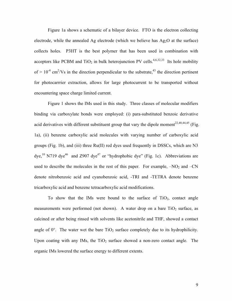
Figure 1a shows a schematic of a bilayer device. FTO is the electron collecting
electrode, while the annealed Ag electrode (which we believe has Ag2O at the surface)
collects holes. P3HT is the best polymer that has been used in combination with
acceptors like PCBM and TiO2 in bulk heterojunction PV cells.4,6,32,33 Its hole mobility
of > 10-4 cm2/Vs in the direction perpendicular to the substrate,43 the direction pertinent
for photocarrrier extraction, allows for large photocurrent to be transported without
encountering space charge limited current.
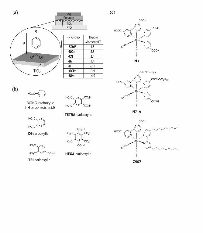
Figure 1 shows the IMs used in this study. Three classes of molecular modifiers
binding via carboxylate bonds were employed: (i) para-substituted benzoic derivative
acid derivatives with different substituent group that vary the dipole moment22,40,44,45 (Fig.
1a), (ii) benzene carboxylic acid molecules with varying number of carboxylic acid
groups (Fig. 1b), and (iii) three Ru(II) red dyes used frequently in DSSCs, which are N3
dye,10 N719 dye46 and Z907 dye47 or “hydrophobic dye” (Fig. 1c). Abbreviations are
used to describe the molecules in the rest of this paper. For example, –NO2 and –CN
denote nitrobenzoic acid and cyanobenzoic acid, -TRI and -TETRA denote benzene
tricarboxylic acid and benzene tetracarboxylic acid modifications.
To show that the IMs were bound to the surface of TiO2, contact angle
measurements were performed (not shown). A water drop on a bare TiO2 surface, as
calcined or after being rinsed with solvents like acetonitrile and THF, showed a contact
angle of 0°. The water wet the bare TiO2 surface completely due to its hydrophilicity.
Upon coating with any IMs, the TiO2 surface showed a non-zero contact angle. The
organic IMs lowered the surface energy to different extents.
Page 10
10
The difference in binding constants to TiO2 and molecular sizes of the IM affects
surface coverage. Kruger et. al showed that even though the attachment groups of the
molecules with –NO2 and –OCH3 have different acidity, the surface concentration of
adsorbed –NO2 and –OCH3 on TiO2 at monolayer coverage was similar with surface area
per molecule of ~ 0.3 nm2.22 On the other hand, the area occupied by N3 molecules at
full monolayer coverage was found to be 1.65 nm2 due to its larger molecular size.10
Note that a monolayer coverage of a particular type of modifiers does not necessary mean
perfect coverage, as additional coadsorption of smaller molecules45 and intercalation of
solvent molecules can be possible.44
A. Band edge shift
One effect the IMs have is to change the band offset at the interface by forming a
layer of dipoles. Depending on the chemical nature of the IM, there can be two
contributions: (i) the molecular dipole, which depends on the electron withdrawing and
donating nature of the atoms across the molecular structure,22 (ii) the protonation of the
TiO2 surface stemming from the dissociative adsorption of the carboxylic acid group to
form a carboxylate bond, in which the positive charge of the proton on the surface and
the negative charge on the carboxylic group forms an interfacial dipole.23,24 The TiO2
band edge has been shown to shift according to the Nernstian potential dependence of 60
mV per pH unit in solution.48
1. Band edge shift due to molecular dipoles
Page 11
11
The use of molecular dipoles to adjust the work function of semiconductors or
metals in general has been widely investigated.40,49 Much of the work was directed
towards improving charge injection from metals into organic materials in organic light
emitting diodes and PV cells.40,50,51 There are few reports of tuning the electron transfer
kinetics and mechanism at a heterojunction interface, and even those were directed at
DSSCs.22,45
We utilized the class of para-substituted benzoic acids investigated
previously22,40,44,45 but included two more derivatives, aminobenzoic acid and
fluorosulfonyl benzoic acid. Depending on the specific functional group substituted at
the para position, the IMs form a dipolar layer with varying dipole direction and strength.
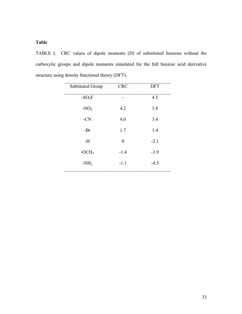
Table I tabulates the dipole moments of these molecules. The left column set was
obtained from literature52 for the corresponding substituted benzene without the
carboxylic group, while the right column set was simulated53 using density functional
theory for the whole structure including the carboxylic group. As carboxylic group forms
a chelating group to Ti(IV) acting like an ester-type linkage, which causes it to be less
electron-withdrawing, the dipole moments of adsorbed molecules are expected to fall
somewhere between those two sets.
This dipolar layer, when attached to the TiO2 surface, induces a step in the local
vacuum level due to the electric field across this layer (Fig. 2). The work function and
the band edge of the TiO2 surface are changed by e∆V, where ∆V is the magnitude of
surface potential change and can be calculated from Poisson’s equation to be:
0
cosεε
θµr
sNV =∆ (1)
Page 12
12
and Ns is the surface dipole concentration, µ is the dipole moment, θ is the angle to which
the dipole makes to the surface normal, εr is the dielectric constant, and ε0 is the
permittivity of free space. A linear relationship between the work function change of
TiO2 and the dipole moments of these para-substituted benzoic acid derivatives was
determined previously using a Kelvin probe.22,44
Figure 2 illustrates schematically the energy band diagram for flat band
conditions of a bilayer TiO2/polymer system with and without a dipole sheet between
them. Figure 2a shows that when the dipole is directed towards the TiO2, the band edge
potential of TiO2 shifts away from the local vacuum level of the polymer. Thus the
effective gap between the conduction band (Ec) of TiO2 and the highest occupied
molecular orbitals (HOMO) of polymer reduces when compared to unmodified TiO2 in
Figure 2b. If the dipoles are pointing away from titania, the band edge of titania shifts
closer to the vacuum level of the polymer, and the gap between Ec and HOMO increases
(Fig. 2c). Because the typical photocarrier concentration of 1015 - 1016 cm-3 under usual
illumination is smaller than the valence and conduction edge density of states, the Voc,
the split between the electron and hole quasi Fermi levels under illumination, is limited
by the effective Ec – HOMO gap. The presence of a dipole layer changing the effective
Ec – HOMO gap consequently affects the maximum attainable Voc. Although the
maximum Voc attainable is thermodynamically limited by this gap, the actual Voc
observed critically depends on the recombination kinetics of charge carriers (Sec. D).
Figure 2 is drawn such that flat band condition is assumed to be close to the open circuit
condition, although we acknowledge the existence of diffusion photocurrent away from
the heterojunction causes the band to slope slightly at open circuit condition.11,54
Page 13
13
The TiO2 samples modified with various molecular dipoles were used to fabricate
bilayer TiO2/P3HT devices. Figure 3 shows the device characteristics in the dark and
under AM 1.5 illumination. A thick polymer layer (~160 nm) was used to improve the
device yield and to obtain more reproducible dark current, which is affected by shunting
when the polymer film is thin. Any difference in the J-V characteristics shown in Figure
3 arises from the existence of the molecular dipoles. The dark J-V curves in Figure 3a
have similar shapes, and differ only by an offset along the voltage axis. The amount of
voltage shift between the devices of ~ 250 mV has been previously observed in solid
state DSSCs.22
The Voc of P3HT devices is plotted against the calculated dipole moments of the
molecular dipoles in Figure 3c. Voc correlates very well with the dipole magnitude.
Dipoles pointing at TiO2 decreased Voc by as much as 0.2 V, whereas dipoles pointing
away from TiO2 only increased Voc by at most 0.03 – 0.05 V. The small increment in Voc
with dipoles pointing away from titania is possibly due to the opposite dipole
contribution from protonation effect of the carboxylic acid group (Sec. A.2). In Figure 3c,
this protonation contribution, determined from the vertical difference between the Voc of
the unmodified cell and the dashed line, is found to be ~ 0.06 – 0.07 V. The relative Voc
change with different molecular dipoles is reproducible, though the absolute Voc between
batches of films can vary by ± 30 mV. If we assume a previously measured Ns of 3 x
1018 m-2 and εr = 5.3 22,44 in Eq. 1, a 0.85 V shift of the Voc is expected with –NO2
modification if the dipoles are oriented normal to the surface. The reduced magnitude of
Voc change with dipole moment in a real device is attributable to different orientation of
the dipoles in contact with polymers,55 a higher effective εr or a lower Ns.
Page 14
14
That the trend of Voc change and the dark current translation is correlated to the
dipole moments of the IM strongly suggests that the main effect of the dipole is to change
the energy offset at the TiO2/polymer interface. There is no evidence of the IMs acting as
physical tunneling barrier that suppresses recombination. The recombination kinetics
difference is thus dominated by the energy offset at the interface. When the Ec – HOMO
gap is smaller, the electron concentration in TiO2 and hole concentration in P3HT are
higher at a given voltage. Higher carrier concentration results in faster charge
recombination rate and higher dark current. The earlier turn-on of dark current
consequently results in a lower Voc.
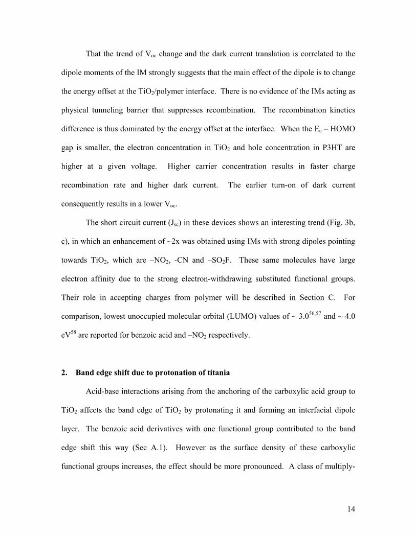
The short circuit current (Jsc) in these devices shows an interesting trend (Fig. 3b,
c), in which an enhancement of ~2x was obtained using IMs with strong dipoles pointing
towards TiO2, which are –NO2, -CN and –SO2F. These same molecules have large
electron affinity due to the strong electron-withdrawing substituted functional groups.
Their role in accepting charges from polymer will be described in Section C. For
comparison, lowest unoccupied molecular orbital (LUMO) values of ~ 3.056,57 and ~ 4.0
eV58 are reported for benzoic acid and –NO2 respectively.
2. Band edge shift due to protonation of titania
Acid-base interactions arising from the anchoring of the carboxylic acid group to
TiO2 affects the band edge of TiO2 by protonating it and forming an interfacial dipole
layer. The benzoic acid derivatives with one functional group contributed to the band
edge shift this way (Sec A.1). However as the surface density of these carboxylic
functional groups increases, the effect should be more pronounced. A class of multiply-
Page 15
15
substituted benzene carboxylic acid molecules, shown in Figure 1b, was used. This class
of molecules has increasing number of functional groups for protonation with varying
pKa. Since their molecular dipoles are small compared to the para-substituted benzoic
acid derivatives, the interfacial dipoles need to be mainly considered. The change in
band edge due to this protonation effect is equivalently described by Figure 3a.
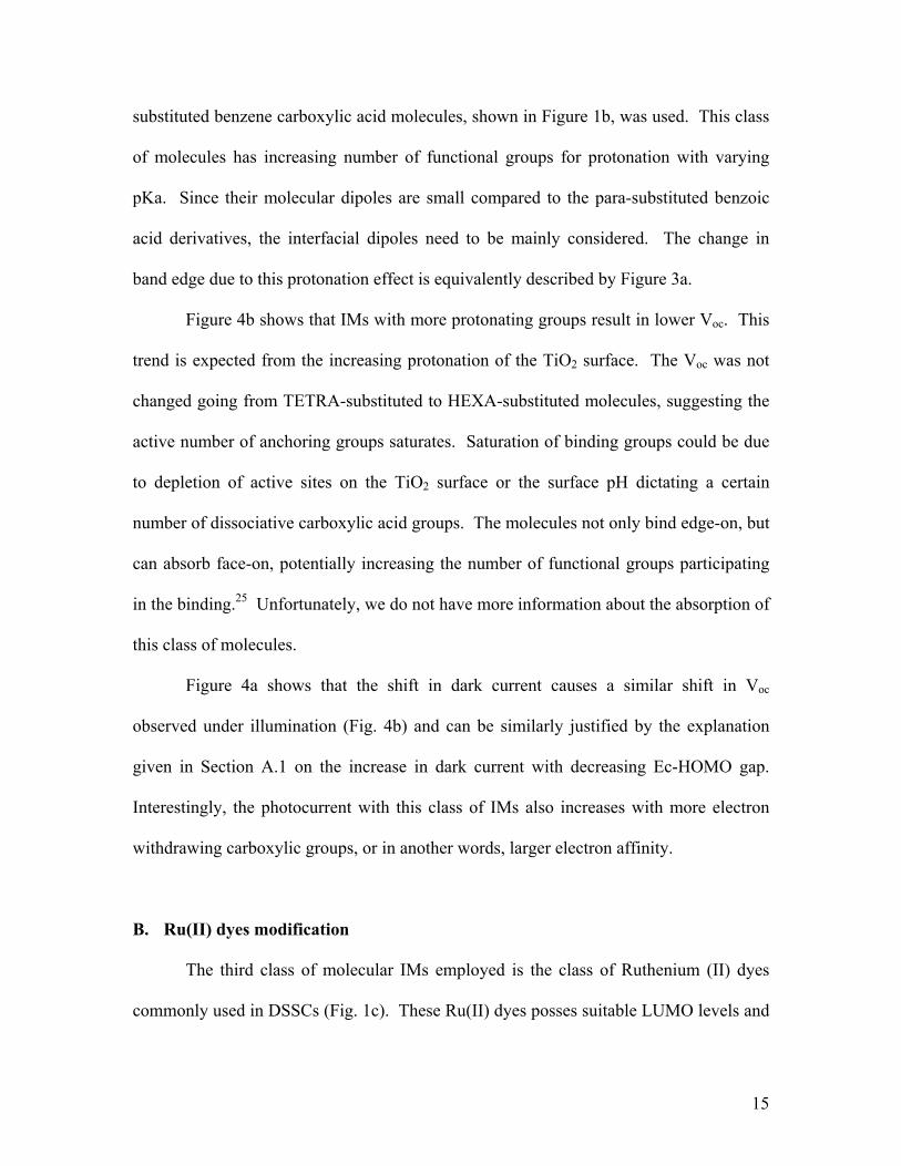
Figure 4b shows that IMs with more protonating groups result in lower Voc. This
trend is expected from the increasing protonation of the TiO2 surface. The Voc was not
changed going from TETRA-substituted to HEXA-substituted molecules, suggesting the
active number of anchoring groups saturates. Saturation of binding groups could be due
to depletion of active sites on the TiO2 surface or the surface pH dictating a certain
number of dissociative carboxylic acid groups. The molecules not only bind edge-on, but
can absorb face-on, potentially increasing the number of functional groups participating
in the binding.25 Unfortunately, we do not have more information about the absorption of
this class of molecules.
Figure 4a shows that the shift in dark current causes a similar shift in Voc
observed under illumination (Fig. 4b) and can be similarly justified by the explanation
given in Section A.1 on the increase in dark current with decreasing Ec-HOMO gap.
Interestingly, the photocurrent with this class of IMs also increases with more electron
withdrawing carboxylic groups, or in another words, larger electron affinity.
B. Ru(II) dyes modification
The third class of molecular IMs employed is the class of Ruthenium (II) dyes
commonly used in DSSCs (Fig. 1c). These Ru(II) dyes posses suitable LUMO levels and
Page 16
16
exhibit binding to TiO2 that allow rapid electron transfer (< 50 fs)10 to TiO2 . The LUMO
levels (~ 3.95 eV)59 also sit between the LUMO of P3HT (~ 3.0 eV) and the Ec of TiO2 (~
4.2 eV) and can possibly mediate charge transfer from the polymer to TiO2. The energy
levels of the three-layer system are such that the electron travels in one direction from the
polymer to TiO2 via the IM but is potentially inhibited from recombining with the
polymer. These Ru(II) molecules possess a similar density of carboxylic acid group as
the multiply-substituted benzene carboxylic acid molecules (Sec. A.2), thus a band edge
shift in the TiO2 of similar magnitude (~0.2 V) is expected upon attachment of these
molecules. These molecules also possess small molecular dipoles resulting from the
spatial asymmetry of the HOMO and the LUMO.10
The three Ru(II) dyes investigated as IMs are respectively N3, N719 and Z907.
N3 is the most common dye used in DSSCs and exhibits fast electron transfer to TiO2
upon photoexcitation.10 N719 dye is similar in most aspects to N3 except the hydrogen
of two of the carboxylic groups is substituted with tetrabutylammonium (TBA). This less
protonated N719 dye resulted in an Ec closer to the vacuum level and showed higher Voc
when used in DSSCs.23,46 Z907 dye is attractive because its amphiphilic nature improves
interactions with polymers47,60 and its alkyl chain is known to inhibit recombination and
improve Voc.38,61
Figure 5a plots the dark current of devices with these dye modifications. Figure
5b shows that all surface modifiers except for the Z907 dye reduced the Voc. The
reduction in Voc is due to the protonation of the TiO2 by the carboxylic acid. The N3-
modified device showed the lowest Voc, but if N719 with fewer carboxylic groups was
used, the Voc was increased by ~ 60 mV. In addition, we also employed the additive tert-
Page 17
17
butylpyridine (TBP), which is known both to shift the band edge of TiO2 upwards due to
its basicity and to physically plug voids at the interface at the molecular scale, to increase
the Voc.62,63 For both N3 and N719-modified titania, TBP increased the Voc by another
~60-70 mV. All these shifts in Voc are consistent with the picture of band edge shift due
to interfacial dipoles. Interestingly, the hydrophobic dye Z907 actually enhanced the Voc,
even though the attachment of the molecules is achieved similarly through carboxylate
groups. This is not surprising considering that that Z907 is known to slow down the
recombination kinetics in solid state DSSCs61 and zinc oxide/polymer devices.38 Its 9-
carbon alkyl chain has been credited for forming charge carrier recombination barrier.61
Figure 5b shows the photocurrent curves for the same devices. N3 and N719 dyes
were found to enhance Jsc by ≥ 2x, while Z907 increased it by 60-70%. The photocurrent
enhancement could not come from the sensitization effect of the dyes, because the
absorption of a monolayer of these dyes is negligible. Photocurrent action spectra of
these devices in Figure 5c show that there is no contribution beyond the adsorption edge
of P3HT even though the dyes absorb out to 800 nm.38 When normalized, the
photocurrent action spectra in Figure 5c overlay on each other and match the absorption
spectrum of P3HT. Section C explains that this enhanced Jsc originates from higher
exciton quenching when TiO2 is modified with the dyes
The N3 and N719-modified devices gave rise to slightly different enhancement,
probably due to the different electronic coupling at the TiO2/dye or dye/polymer interface.
An interesting observation is that upon treatment with TBP, both N3 and N719 devices
retained similar Jsc. This suggests that there is not always a tradeoff between Jsc and Voc.
In the case of Z907 modification, both Jsc and Voc actually improved. Therefore, the
Page 18
18
explanation of TiO2 band edge shift increasing the driving force for forward charge
transfer, which ultimately increases the charge transfer yield, is not applicable.
The lesser photocurrent enhancement from Z907 dye is intriguing. With similar
LUMO levels and charge transfer property as the other two Ru(II) dyes, Z907 is expected
to behave similarly. The uniqueness lies in its alkyl chains. At the same time that these
insulating segments slow down charge carrier recombination and increase Voc, the
forward charge transfer from the polymer to the TiO2 is also partially inhibited by the
extending alkyl chains. This slower forward charge transfer rate may explain the smaller
Jsc enhancement. Z907 is an attractive IM candidate in nanostructured metal
oxides/polymer devices because it potentially imparts slow recombination kinetics to
offset large recombination interface to maintain large Voc and fill factor. A recent work
also showed the concomitant benefit of using Z907, which is to increase the incorporation
of P3HT in nanostructured template.60
C. Models for increased photocurrent yield
The modifications with all three groups of IMs resulted in enhanced photocurrent,
by > 2x in some cases. We discussed earlier that the ability of IM to accept electrons
from the polymer is closely linked to the enhanced photocurrent in devices. The charge
accepting ability was revealed in a PL quenching experiment probing blends of P3HT
with 2.5 mol % IM spun from THF solutions (not shown). The PL of P3HT is quenched
in the vicinity of electron acceptors. IMs that enhance device photocurrent were
consistently found to accept charges from P3HT.
Page 19
19
The exact nature of exciton quenching by the IM is expected to differ in a blend
compared to a monolayer on a flat surface. The quenching by a monolayer of IM
attached onto TiO2 is more relevant to working PV devices. By comparing the PL
intensity of a polymer film on a planar quenching substrate and a non-quenching
substrate for a range of polymer film thickness, the exciton diffusion length (Ld) can be
determined.64-66 Glass was used as the non-quenching substrate, while a thin layer of
TiO2 coated on glass with or without IM was the quenching substrate. Thin TiO2 (~5 – 8
nm) was used to ensure a negligible effect from optical interference.29,65 The variation in
polymer film thickness spun on different modified TiO2 surface was usually ± 1 nm.
Film thickness was determined from the optical density.
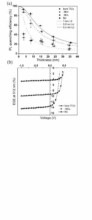
Figure 6a shows the PL quenching as a function of P3HT film thickness. When
deposited on bare TiO2 or –NH2 modified TiO2, P3HT exhibits some quenching at large
thickness, but the quenching never approaches 100% as its thickness is reduced.64 This
lack of complete quenching is unexpected because in very thin film of polymers (d < Ld),
all the excitons should be able to diffuse to the quenching interface. For thin films where
the absorption is assumed to be linear with thickness, the quenching profile follows:66
)]/2exp(1[)]/2exp(1[
D
Ddquenching Ldd
LdLPL
−+−−
= (2)
We extracted an Ld by fitting data to Eq. 2 to allow for comparison between the data sets.
Figure 6a shows that when P3HT was deposited on –NO2 modified TiO2, the PL
quenching is about twice as high compared to that on bare TiO2 at large thickness and
approaches 100% with decreasing film thicknesses. When the TiO2 was modified with
N3 dye, a slightly higher quenching was observed. The Ld extracted for –NO2 modified
and N3-modiifed substrates are 6.5 and 8.5 nm respectively. It is observed that among
Page 20
20
other IMs used, only those with large electron affinity result in higher PL quenching. A
similar Ld value for P3HT of 9 nm measured using triplet-triplet annihilation method was
recently reported by I.D.W. Samuel.67
To see if the difference between the PL quenching magnitudes observed on bare
and modified TiO2 was due to difference in polymer film roughness, we performed AFM
measurements. AFM micrograph of a 3.3 nm thick P3HT film on the different substrates
showed that the polymer film covered the TiO2 surfaces completely and exhibited similar
surface Rms roughness of 0.4 – 0.45 nm (not shown). For comparison, the surface
roughness of bare TiO2 is only 0.27 nm. There was no polymer surface roughness
difference to explain the PL quenching difference.
To prove that there is no diffusion of these IMs into the polymer causing PL
quenching, we accounted for all the quenched excitons in photocurrent. Figure 6b shows
EQE measurements of sufficiently thick P3HT (160 nm) bilayer devices. At this film
thickness, the optical interference effect is negligible and the absorption profile follows
Beer’s Law. For a given Ld and a flat quenching surface and neglecting the reflectance
loss, the EQE is expected as:65,68
)1( ααd
d
LL
EQE+
= (3)
The absorption coefficient, α, at 512 nm for P3HT is 1.9 x 105 cm-1. The J-V curve for
the unmodified cell shows saturated photocurrent with increasing reverse bias, indicating
that geminate recombination is not a bottleneck and any photocurrent enhancement is not
due to the competition between recombination and charge extraction. Experimentally,
the EQE obtained on –NO2 device is twice that on the unmodified cell, and the EQE of
~10 % at 512 nm is expected for Ld of 6.5 nm. Similarly the EQE value of ~14%
Page 21
21
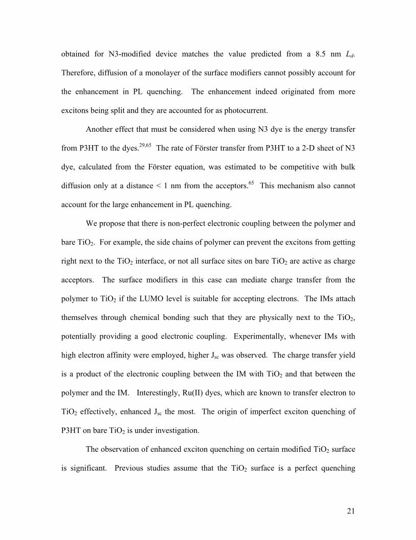
obtained for N3-modified device matches the value predicted from a 8.5 nm Ld.
Therefore, diffusion of a monolayer of the surface modifiers cannot possibly account for
the enhancement in PL quenching. The enhancement indeed originated from more
excitons being split and they are accounted for as photocurrent.
Another effect that must be considered when using N3 dye is the energy transfer
from P3HT to the dyes.29,65 The rate of Förster transfer from P3HT to a 2-D sheet of N3
dye, calculated from the Förster equation, was estimated to be competitive with bulk
diffusion only at a distance < 1 nm from the acceptors.65 This mechanism also cannot
account for the large enhancement in PL quenching.
We propose that there is non-perfect electronic coupling between the polymer and
bare TiO2. For example, the side chains of polymer can prevent the excitons from getting
right next to the TiO2 interface, or not all surface sites on bare TiO2 are active as charge
acceptors. The surface modifiers in this case can mediate charge transfer from the
polymer to TiO2 if the LUMO level is suitable for accepting electrons. The IMs attach
themselves through chemical bonding such that they are physically next to the TiO2,
potentially providing a good electronic coupling. Experimentally, whenever IMs with
high electron affinity were employed, higher Jsc was observed. The charge transfer yield
is a product of the electronic coupling between the IM with TiO2 and that between the
polymer and the IM. Interestingly, Ru(II) dyes, which are known to transfer electron to
TiO2 effectively, enhanced Jsc the most. The origin of imperfect exciton quenching of
P3HT on bare TiO2 is under investigation.
The observation of enhanced exciton quenching on certain modified TiO2 surface
is significant. Previous studies assume that the TiO2 surface is a perfect quenching
Page 22
22
interface. This assumption was made because some experiments had shown that the
exciton lifetime in conjugated polymer was significantly shortened in the presence of
TiO2. The lifetime of MEH-PPV has been shown to reduce from 300 ps to <10 ps.31 and
another work showed < 100 fs.69 That of the oligomeric thiophene was shortened from
230 ps to < 6 ps.70 This indicates that the charge transfer from polymer to bare TiO2 can
be very fast. Further improvement in the forward charge transfer rate cannot improve
exciton splitting significantly. It is likely that IMs with suitable LUMO levels mediate
charge transfer from P3HT to TiO2, thereby bypassing some barriers and improving
exciton harvesting. There should be relevance of the IM’s LUMO participation in the
charge transfer process as excitons encounter the IM prior to TiO2.
D. Transient photovoltage measurement of recombination kinetics
In section A and B, the dark current of PV devices was compared to understand
how the Voc changes with interface modification. It was argued that the dark current is
higher at a fixed voltage if the Ec – LUMO gap is smaller due to higher electron and hole
carrier concentration. The recombination rate in operating devices was determined by
making transient photovoltage measurement (TPV) measurements.41 In a TPV
measurement (Fig. 7a), devices are held at a steady state Voc, the magnitude of which is
adjusted by varying the intensity of a bias lamp. A pulsed light creates a small
perturbation to the Voc by transiently generating electrons and holes. At Voc, these
additional carriers (photovoltage) decay with the lifetime determined by the rate of
charge carriers recombining across the heterojunction interface. Figure 7b shows a
typical TPV curve. The decay curve can be fitted to a monoexponential decay to extract
Page 23
23
a characteristics lifetime, τ. The effective recombination rate, krec, is 1/τ. If
recombination is assumed to be second order bimolecular, the recombination rate
pnBdtnd ⋅⋅−=)( (5)
depends on the bimolecular recombination rate constant B, and the electron and hole
concentration. As quasi Fermi levels approach the band edges or Voc increases, the
charge carrier concentrations increase exponentially. At the same time, the mobility of
charge carriers improves as more traps become filled. Improved mobility consequently
increases the frequency of opposite charge carriers encountering each other at the
interface, which enhances B for a diffusion limited recombination mechanism. Therefore
the recombination rate is expected to increase with Voc. Figure 7c depicts the plot of krec
versus Voc of different devices. The recombination rate was found to increase
exponentially with bias, a characteristic that has been observed in DSSCs system.23,41,62
For these TiO2/P3HT devices, the slopes were found to be ~0.55 – 0.6 decade per 100
mV.
Most cells exhibit recombination rates of 103 - 105 s-1 at operating conditions.
The right most point of each data set corresponds approximately to 1 sun intensity.
Compared to the unmodified cell, all devices exhibit similar recombination rate constant
curve shape (Fig. 7c). The same slopes suggest that interface modification has not altered
the underlying recombination mechanism. Devices with earlier turn-on of dark current
exhibit faster recombination rate as expected. The difference in the curves in Figure 7c
can either be due to a translation along the Voc axis, which is related to the changes in the
effective Ec – HOMO gap, or a translation along the krec axis, which is related to the
change in B. With the clear trend of how dipoles affects the Voc (Sec. A), the main
Page 24
24
contribution still comes from a shift in band edge offset at the TiO2/polymer interface.
The only exception is that the Z907 dye actually reduces the recombination rate because
the alkyl chains form a charge carrier recombination barrier.
It is interesting that a layer of IMs does not have an effect on slowing down
recombination, except Z907 with long alkyl chains. These results are similar to what was
previously observed, that the IMs act more as an agent that modulates the interface
energetics,22 than as a recombination barrier. Researchers have investigated the use of a
large bandgap inorganic material in DSSCs as charge transfer barriers.41,71 The
“monolayer” of IMs used here are less effective as recombination barrier probably due to
imperfect coverage at the molecular scale or due to its π-conjugated semiconducting
nature. It is also possible that the recombination across the TiO2/P3HT interface is
diffusion limited and a small alteration in the reaction rate has no effect on the
recombination.
E. Optimized bilayer
Experimental results in earlier sections were obtained using a thick polymer layer
so that the dark current could be more reproducible, and allowed analysis that assumes
Beer’s Law absorption. Here the characteristics of a bilayer cell was improved by
optimizing layer thickness14,66,72,73 to maximize the optical field close to the exciton
splitting interface. This ensures a higher concentration of excitons is generated within a
diffusion length away from the interface. Figure 8a shows the optical power profile at
532 nm wavelength (close to P3HT absorption maximum) inside a device stack with an
optimum P3HT thickness of 50 nm. Figure 8b shows the J-V characteristics of actual
Page 25
25
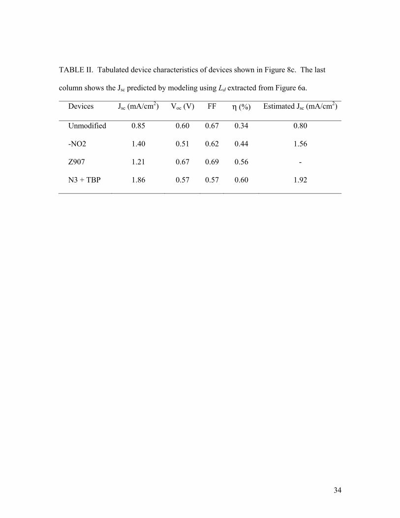
bilayer TiO2/P3HT devices with three different IMs. Table II summarizes the device
characteristics of these devices and the Jsc predicted based on Ld extracted from Figure 6a.
As compared to earlier devices with thicker P3HT, the devices here typically exhibit ~1.5
times higher Jsc, while the Voc is retained. The EQE of N3 modified devices was
measured to be 19.5%, close to the estimated 20%. Jsc is highly reproducible to within
±10% and in devices with rectification ratios above 103 at -1V and 1 V, Voc is consistent
within ±15 mV. The power efficiency of some of these thin bilayer devices (or trilayer
devices counting the IMs as a layer) approach 0.60 %.
IV. CONCLUSION
This work systematically studies the effect of interface modification in hybrid
inorganic-organic PV cells and has provided insight to its device physics. It provides
design strategy to improve this type of cell. We showed that both molecular dipoles and
acid-base interaction can cause a band edge shift in TiO2, resulting in a change in Voc.
This work illustrates that surface modification needs to take into account the effect of
dipoles on the band edge shift, and the inevitable effects of protonation from carboxylic,
phosphonic or sulfonic anchoring groups. We measured a larger Ld of P3HT of 6.5 – 8.5
nm on certain surface-modified TiO2 compared to bare TiO2, and showed that electron
accepting nature of the IM is likely responsible for the photocurrent enhancement in PV
devices. This larger Ld than previously thought has significant implications, for example,
the dimensions of nanostructure in bulk-heterojunction PV cells needed for achieving
efficient exciton harvesting may be relaxed. Utilizing the knowledge learned in this work,
we increased the power efficiency of planar TiO2/P3HT devices from 0.34 % to 0.6 %
Page 26
26
with Ru(II) dye modifications. Z907 dye showed promises as the IM for use in bulk
heterojunction nanostructured metal oxide-polymer PV cells due to its desirable
properties of suppressing charge carrier recombination while retaining efficient exciton
harvesting.
ACKNOWLEDGEMENTS
This work was supported by the Global Climate and Energy Project at Stanford
University, the Department of Energy and a Kodak Research Fellowship. The authors
would like to thank Colin Reese for simulating the dipole moments of the benzoic acid
derivatives and Dr. Brian O’Regan for insightful discussions.
Page 27
27
REFERENCES
1C. W. Tang, Appl. Phys. Lett. 48, 183 (1986).
2G. Yu, J. Gao, J. C. Hummelen, F. Wudl, and A. J. Heeger, Science 270, 1789 (1995).
3J. Halls, C. Walsh, N. Greenham, E. Marseglia, R. Friend, S. Moratti, and A. Holmes,
Nature 376, 498 (1995).
4W. Ma, C. Yang, X. Gong, K. Lee, and A. J. Heeger, Adv. Funct. Mater. 15, 1617
(2005).
5F. Yang, M. Shtein, and S. R. Forrest, Nat. Mater. 4, 37 (2005).
6G. Li, V. Shrotriya, J. S. Huang, Y. Yao, T. Moriarty, K. Emery, and Y. Yang, Nat.
Mater. 4, 864 (2005).
7S. E. Shaheen, D. S. Ginley, and G. E. Jabbour, MRS Bulletin 30, 10 (2005).
8B. O'Regan, and M. Gratzel, Nature 353, 737 (1991).
9U. Bach, D. Lupo, P. Comte, J. Moser, F. Weissortel, J. Salbeck, H. Spreitzer, and M.
Gratzel, Nature 395, 583 (1998).
10A. Hagfeldt, and M. Gratzel, Accounts Chem. Res. 33, 269 (2000).
11B. Gregg, J. Phys. Chem. B 107, 4688 (2003).
12I. G. Hill, A. Kahn, Z. G. Soos, and R. A. Pascal, Chem. Phys. Lett. 327, 181 (2000).
13J. L. Bredas, J. Cornil, and A. J. Heeger, Adv. Mater. 8, 447 (1996).
14L. A. A. Pettersson, L. S. Roman, and O. Inganas, J. Appl. Phys. 86, 487 (1999).
15M. Theander, A. Yartsev, D. Zigmantas, V. Sundstrom, W. Mammo, M. Andersson,
and O. Inganas, Phys. Rev. B 61, 12957 (2000).
Page 28
28
16J. Halls, K. Pichler, R. Friend, S. Moratti, and A. Holmes, Appl. Phys. Lett. 68, 3120
(1996).
17J. E. Kroeze, T. J. Savenije, M. J. W. Vermeulen, and J. M. Warman, J Phys. Chem. B
107, 7696 (2003).
18D. E. Markov, E. Amsterdam, P. W. M. Blom, A. B. Sieval, and J. C. Hummelen, J.
Phys. Chem. A 109, 5266 (2005).
19P. Peumans, and S. R. Forrest, Chem. Phys. Lett. 398, 27 (2004).
20V. D. Mihailetchi, L. J. A. Koster, J. C. Hummelen, and P. W. M. Blom, Phys. Rev.
Lett. 93, 216601 (2004).
21T. Offermans, S. C. J. Meskers, and R. A. J. Janssen, Chem. Phys. 308, 125 (2005).
22J. Kruger, U. Bach, and M. Gratzel, Adv. Mater. 12, 447 (2000).
23J. R. Durrant, S. A. Haque, and E. Palomares, Coord. Chem. Rev. 248, 1247 (2004).
24Y. X. Liu, S. R. Scully, M. D. McGehee, J. S. Liu, C. K. Luscombe, J. M. J. Frechet, S.
E. Shaheen, and D. S. Ginley, J Phys. Chem. B 110, 3257 (2006).
25J. Moser, S. Punchihewa, P. P. Infelta, and M. Gratzel, Langmuir 7, 3012 (1991).
26R. Cohen, L. Kronik, A. Shanzer, D. Cahen, A. Liu, Y. Rosenwaks, J. K. Lorenz, and A.
B. Ellis, J. Am. Chem. Soc. 121, 10545 (1999).
27R. J. Kline, M. D. Mcgehee, and M. F. Toney, Nat. Mater. 5, 222 (2006).
28A. Salleo, M. L. Chabinyc, M. S. Yang, and R. A. Street, Appl. Phys. Lett. 81, 4383
(2002).
29Y. X. Liu, M. A. Summers, C. Edder, J. M. J. Frechet, and M. D. McGehee, Adv. Mater.
17, 2960 (2005).
Page 29
29
30P. A. van Hal, M. P. T. Christiaans, M. M. Wienk, J. M. Kroon, and R. A. J. Janssen, J.
Phys. Chem. B 103, 4352 (1999).
31P. van Hal, M. Wienk, J. Kroon, W. Verhees, L. Slooff, W. van Gennip, P. Jonkheijm,
and R. Janssen, Adv. Mater. 15, 118 (2003).
32W. J. E. Beek, M. M. Wienk, and R. A. J. Janssen, Adv. Mater. 16, 1009 (2004).
33A. Arango, L. Johnson, V. Bliznyuk, Z. Schlesinger, S. Carter, and H. Horhold, Adv.
Mater. 12, 1689 (2000).
34K. M. Coakley, Y. X. Liu, M. D. McGehee, K. L. Frindell, and G. D. Stucky, Adv.
Funct. Mater. 13, 301 (2003).
35K. M. Coakley, and M. D. McGehee, Appl. Phys. Lett. 83, 3380 (2003).
36K. M. Coakley, and M. D. McGehee, Chem. Mater. 16, 4533 (2004).
37C. Goh, K. M. Coakley, and M. D. McGehee, Nano Lett. 5, 1545 (2005).
38P. Ravirajan, A. M. Peiro, M. K. Nazeeruddin, M. Graetzel, D. D. C. Bradley, J. R.
Durrant, and J. Nelson, J. Phys. Chem. B 110, 7635 (2006).
39D. C. Olson, J. Piris, R. T. Collins, S. E. Shaheen, and D. S. Ginley, Thin Solid Films
496, 26 (2006).
40G. Ashkenasy, D. Cahen, R. Cohen, A. Shanzer, and A. Vilan, Accounts Chem. Res. 35,
121 (2002).
41B. C. O'Regan, S. Scully, A. C. Mayer, E. Palomares, and J. Durrant, J. Phys. Chem. B
109, 4616 (2005).
42T. Stubinger, and W. Brutting, J. Appl. Phys. 90, 3632 (2001).
43C. Goh, R. J. Kline, M. D. McGehee, E. N. Kadnikova, and J. M. J. Frechet, Appl. Phys.
Lett. 86, 122110 (2005).
Page 30
30
44F. Nuesch, M. Carrara, and L. Zuppiroli, Langmuir 19, 4871 (2003).
45S. Ruhle, M. Greenshtein, S. G. Chen, A. Merson, H. Pizem, C. S. Sukenik, D. Cahen,
and A. Zaban, J Phys. Chem. B 109, 18907 (2005).
46M. K. Nazeeruddin, S. M. Zakeeruddin, R. Humphry-Baker, M. Jirousek, P. Liska, N.
Vlachopoulos, V. Shklover, C. H. Fischer, and M. Gratzel, Inorg. Chem. 38, 6298 (1999).
47P. Wang, S. M. Zakeeruddin, J. E. Moser, M. K. Nazeeruddin, T. Sekiguchi, and M.
Gratzel, Nat. Mater. 2, 402 (2003).
48G. Rothenberger, D. Fitzmaurice, and M. Gratzel, J. Phys. Chem. 96, 5983 (1992).
49L. Zuppiroli, L. Si-Ahmed, K. Kamaras, F. Nuesch, M. N. Bussac, D. Ades, A. Siove, E.
Moons, and M. Gratzel, Eur. Phys. J. B 11, 505 (1999).
50S. Khodabakhsh, D. Poplavskyy, S. Heutz, J. Nelson, D. D. C. Bradley, F. Murata, and
T. S. Jones, Adv. Funct. Mater. 14, 1205 (2004).
51B. de Boer, A. Hadipour, M. M. Mandoc, T. van Woudenbergh, and P. W. M. Blom,
Adv. Mater. 17, 621 (2005).
52D. R. Lide, Ed. (2006). CRC Handbook of Chemistry and Physics. Boca Raton, Taylor
and Francis.
53simulated using density functional theory with 6-311++Gdp basis set
54J. A. Barker, C. M. Ramsdale, and N. C. Greenham, Phys. Rev. B 67, 075205 (2003).
55T. F. Heinz, H. W. K. Tom, and Y. R. Shen, Phys. Rev. A 28, 1883 (1983).
56J. A. Harrison, and D. W. Shoesmit*, J. of Electroanal. Chem. 32, 125 (1971).
57J. Weber, and J. Volke, Electrochim. Acta 24, 113 (1979).
58E. D. Clarke, P. Wardman, and K. H. Goulding, Biochemical Pharmacology 29, 2684
(1980).
Page 31
31
59A. Hagfeldt, and M. Gratzel, Chem. Rev. 95, 49 (1995).
60G. P. Bartholomew, and A. J. Heeger, Adv. Funct. Mater. 15, 677 (2005).
61L. Schmidt-Mende, J. E. Kroeze, J. R. Durrant, M. K. Nazeeruddin, and M. Gratzel,
Nano Lett. 5, 1315 (2005).
62S. A. Haque, Y. Tachibana, R. L. Willis, J. E. Moser, M. Gratzel, D. R. Klug, and J. R.
Durrant, J. Phys. Chem. B 104, 538 (2000).
63M. K. Nazeeruddin, A. Kay, I. Rodicio, R. Humphrybaker, E. Muller, P. Liska, N.
Vlachopoulos, and M. Gratzel, J. Am. Chem. Soc. 115, 6382 (1993).
64B. A. Gregg, J. Sprague, and M. W. Peterson, J. Phys. Chem. B 101, 5362 (1997).
65S. Scully, and M. D. McGehee, J. Appl. Phys. 100, 034907 (2006).
66P. Peumans, A. Yakimov, and S. R. Forrest, J. Appl. Phys. 93, 3693 (2003).
67I. D. W. Samuel , MRS Fall Meeting (2005).
68obtained by first solving the continuity equation for a TiO2/thick polymer bilayer
geometry assuming exciton diffusion length of Ld and Beer's law generation rate profile,
and then by taking the slope of the steady state exciton concentration profile at the
TiO2/polymer interface, which gives the photocurrent density. EQE is the photocurrent
density divided by the incident photon flux. .
69N. A. Anderson, E. C. Hao, X. Ai, G. Hastings, and T. Q. Lian, Chem. Phys. Lett. 347,
304 (2001).
70W. J. E. Beek, and R. A. J. Janssen, Adv. Funct. Mater. 12, 519 (2002).
71E. Palomares, J. N. Clifford, S. A. Haque, T. Lutz, and J. R. Durrant, J. Am. Chem. Soc.
125, 475 (2003).
Page 32
32
72P. Ravirajan, S. Haque, J. Durrant, D. Poplavskyy, D. Bradley, and J. Nelson, J. Appl.
Phys. 95, 1473 (2004).
73P. Ravirajan, S. A. Haque, D. Poplavskyy, J. R. Durrant, D. D. C. Bradley, and J.
Nelson, Thin Solid Films 451/452, 624 (2004).
Page 33
33
Table
TABLE I. CRC values of dipole moments (D) of substituted benzene without the
carboxylic groups and dipole moments simulated for the full benzoic acid derivative
structure using density functional theory (DFT).
Subtituted Group CRC DFT
-SO2F - 4.5
-NO2 4.2 3.8
-CN 4.0 3.4
-Br 1.7 1.4
-H 0 -2.1
-OCH3 -1.4 -3.9
-NH2 -1.1 -4.5
Page 34
34
TABLE II. Tabulated device characteristics of devices shown in Figure 8c. The last
column shows the Jsc predicted by modeling using Ld extracted from Figure 6a.
Devices Jsc (mA/cm2) Voc (V) FF η (%) Estimated Jsc (mA/cm2)
Unmodified 0.85 0.60 0.67 0.34 0.80
-NO2 1.40 0.51 0.62 0.44 1.56
Z907 1.21 0.67 0.69 0.56 -
N3 + TBP 1.86 0.57 0.57 0.60 1.92
Page 35
35
Figure Captions
FIG. 1. (a) Schematic of bilayer TiO2/polymer devices with dipolar modification of
titania surface. The table lists the substituent –R group on the para position of the
benzoic acid accompanied with calculated dipole moment. (b) Molecular structures of the
benzene carboxylic molecules with varying amount of carboxylic acid groups. (c)
Molecular structures of the three Ru(II) dyes as IM.
FIG. 2. Schematics of band diagram of TiO2/polymer cell at flat band (assumed to be
close to open circuit condition) (a) with interfacial dipoles pointing towards TiO2, (b)
without any modification (c) with interfacial dipoles pointing away from TiO2. Quasi
Fermi levels are drawn as dash lines and the split between them dictates the Voc.
FIG. 3. J-V curves of TiO2/160 nm P3HT bilayer devices with and without interface
modifications employing para-substituted benzoic acid derivatives (a) in dark and (b)
under illuminations. (c) Voc and Jsc of devices shown in b plotted against dipole moment
of the modifiers. A dashed line is drawn as a guide to the eye.
FIG. 4. J-V curves of TiO2/160 nm P3HT bilayer devices with and without interface
modifications employing multiply substituted benzene carboxylic acid molecules (a) in
dark and (b) under illuminations.
Page 36
36
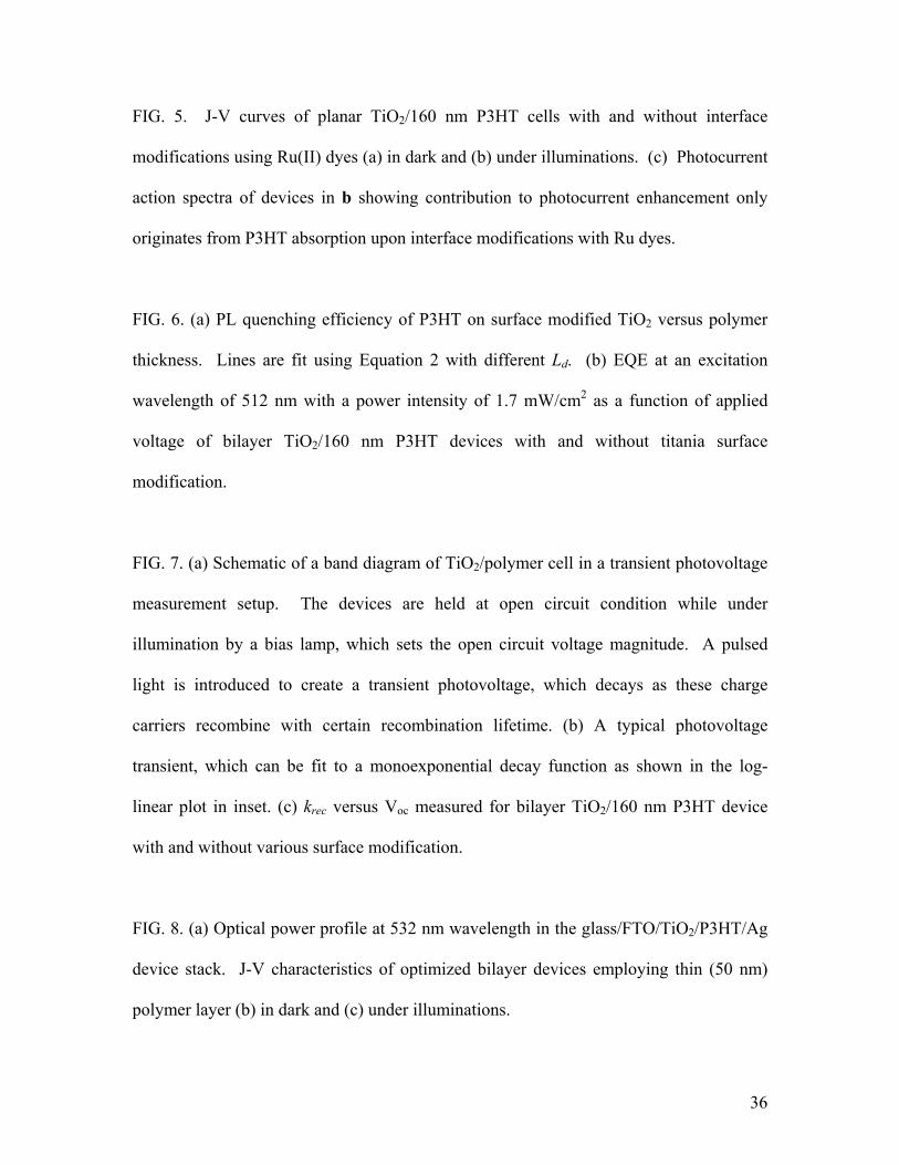
FIG. 5. J-V curves of planar TiO2/160 nm P3HT cells with and without interface
modifications using Ru(II) dyes (a) in dark and (b) under illuminations. (c) Photocurrent
action spectra of devices in b showing contribution to photocurrent enhancement only
originates from P3HT absorption upon interface modifications with Ru dyes.
FIG. 6. (a) PL quenching efficiency of P3HT on surface modified TiO2 versus polymer
thickness. Lines are fit using Equation 2 with different Ld. (b) EQE at an excitation
wavelength of 512 nm with a power intensity of 1.7 mW/cm2 as a function of applied
voltage of bilayer TiO2/160 nm P3HT devices with and without titania surface
modification.
FIG. 7. (a) Schematic of a band diagram of TiO2/polymer cell in a transient photovoltage
measurement setup. The devices are held at open circuit condition while under
illumination by a bias lamp, which sets the open circuit voltage magnitude. A pulsed
light is introduced to create a transient photovoltage, which decays as these charge
carriers recombine with certain recombination lifetime. (b) A typical photovoltage
transient, which can be fit to a monoexponential decay function as shown in the log-
linear plot in inset. (c) krec versus Voc measured for bilayer TiO2/160 nm P3HT device
with and without various surface modification.
FIG. 8. (a) Optical power profile at 532 nm wavelength in the glass/FTO/TiO2/P3HT/Ag
device stack. J-V characteristics of optimized bilayer devices employing thin (50 nm)
polymer layer (b) in dark and (c) under illuminations.