16
1 Greenwald FESAC, Aug. 07 Whyte First Wall Issues: ITER to DEMO D.G. Whyte, B. Lipschultz Plasma Science & Fusion Center, MIT, Cambridge USA Greenwald Panel, FESAC Meeting August 8, 2007
| Date post: | 28-Dec-2015 |
| Category: |
Documents |
| Upload: | brian-caldwell |
| View: | 215 times |
| Download: | 1 times |

1Greenwald FESAC, Aug. 07 Whyte
First Wall Issues:ITER to DEMO
D.G. Whyte, B. LipschultzPlasma Science & Fusion Center, MIT, Cambridge USA
Greenwald Panel, FESAC Meeting
August 8, 2007

2Greenwald FESAC, Aug. 07 Whyte
First-Wall & PSI becoming increasingly important and difficult as we move from present tokamaks
ITER demonstration fusion power plants
Issue / ParameterPresent
TokamaksITER DEMO Consequences
Quiescent energy exhaust
GJ / day ~ 10 3,000 60,000- active cooling
- max. tile thickness ~ 10 mm
Transient energy exhaust from plasma instabilities
T~ MJ / Awall(m2) / (1 ms)1/2 ~ 2 15 60
- require high Tmelt/ablate
- limit? ~ 60 for C and W
- surface distortion
Yearly neutron damage in plasma-facing materials
displacements per atom~ 0 ~ 0.5 20
- evolving material properties: thermal conductivity & swelling
Max. gross material removal rate with 1% erosion yield
(mm / operational-year)< 1 300 3000
- must redeposit locally
- limits lifetime
- produces films
Tritium consumption
(g / day) < 0.02 20 1000- Tritium retention in materials and recovery

3Greenwald FESAC, Aug. 07 Whyte
Upstream peak power exhaust: SOL Width ~ R leads to q//,max ~ 2-3 GW/m2 in reactor
Daunting engineering task, but can we access physics in present devices?
€
q//,MAX ≡PSOL
4π R λ q //
BT
BZ
⎛
⎝ ⎜
⎞
⎠ ⎟sep
~PSOL
R2
qcyl
ε~ q⊥⋅qcyl
q//,sep
(W/m2)
108
109
q//,sep 1.43x10⁴ q0.86 qcyl 1.03
109108
ITER
ARIES-AT
PSOL=0.7 (P+Paux)
Whyte et al. ITPA 07 Garching

4Greenwald FESAC, Aug. 07 Whyte
Tritium/fuel control and retention represents the single largest step between
present devices/ITER and a DEMO

5Greenwald FESAC, Aug. 07 Whyte
High materials temperatures seem mandatory to control fuel retention and anneal neutron damage:
What temperature will be required?
Wampler et al. J. Nucl. Mater. 176 & 177 (1990) 987
Anneal T (C)
1000 CD r
etai
ned
(%)
0
100
Film LocationTmax
(K)
(H+D) / C
Front-face >1000 0.01
Behind tile 420 ~ 1
JT-60U tokamak (Tanabe et al. ITPA Toronto 06)
Thermal conductivity restoredby high-T annealing
L. Snead, T. Burchell,J. Nucl. Mater. 224 (1995) 222.

6Greenwald FESAC, Aug. 07 Whyte
Both long pulse AND high temperatures required to reach true particle equilibrium
in first wall.
ITERambient T
Seconds requiredTo permeate1 cm thickarmour108
106
104
G.M. Wright, Ph.D. thesis, U. Wisc 2007

7Greenwald FESAC, Aug. 07 Whyte
Summary
• The requirements for a sustainable fuel cycle and wall viability push us strongly to investigate first walls with much higher ambient temperatures Tritium recovery, suppression of retention in codeposits. Walls and particles in equilibrium Annealing of neutron damage Technological requirement: gas cooling + peak heat load removal
• A key physics / design issue will be the selection of the ambient temperature that provides the appropriate trade-offs between temperature limits (e.g. heating from transients), desired high power density, and high temperature benefits such as tritium recovery. Exponential T dependences demand experimental demonstration / testing.
• “Hot-wall” tokamak operation would investigate a physics, operational and technological path that seems vital to fusion’s success, but which no one else, including ITER, is pursuing. Must be coupled with a concentrated effort on PSI science and diagnosis +
sustainment physics.
8Greenwald FESAC, Aug. 07 Whyte
Additional Materials

9Greenwald FESAC, Aug. 07 Whyte
Cross-device study that showed no dependence of q with R, also revealed a scaling of q ~ P0.5 that results in
favorable extrapolation to ITER & reactors
ARIES-AT: qpeak ~ 6 MW/m2

10Greenwald FESAC, Aug. 07 Whyte
Target heat removal is the highest priority in edge design, but the strategy forward is confused by the lack of consistent or compelling empirical scalings
“All than can be strongly concludedfrom Table 1 [scalings for SOL heat flux] is thatthere is a need for improved experimentalmeasurements and a theory-orientedapproach for making extrapolationsfor the target heat flux..”Tokamak Physics Update: Power and ParticleControl, A. Loarte, et al. Nucl. Fusion 47 (2007) S203.

11Greenwald FESAC, Aug. 07 Whyte
As Kallenbach1, we find T ~ R. Further regression analysis shows T is invariant with PSOL
and insensitive to other global and separatrix parameters1 Kallenbach,et al. JNM 337-339 (2005) 381.
T ~ R1.1±0.1 q*0.15±0.2 PSOL
0.01±0.05 nsep0.2±0.06
T (
m)
€
T = C0 ⋅ fshape( )BT
BZ
q*
⎛
⎝ ⎜
⎞
⎠ ⎟
2 / 7 ⎡
⎣ ⎢ ⎢
⎤
⎦ ⎥ ⎥
7 / 9
nχ( )7 / 9
⋅ R14 / 9( ) ⋅
1
PSOL5 / 9
The invariance with PSOL counter-indicates the scaling expected from conduction
Whyte et al. ITPA 07 Garching

12Greenwald FESAC, Aug. 07 Whyte
The separatrix seems to exhibit a critical gradient scale length set by R
Te (eV)
Rsep / Ro
AUGDIII-DJETC-ModJT-60U
Whyte et al. ITPA 07 Garching
13Greenwald FESAC, Aug. 07 Whyte
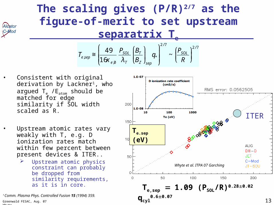
The scaling gives (P/R)2/7 as the figure-of-merit to set upstream separatrix Te
• Consistent with original derivation by Lackner1, who argued Te /Eatom should be matched for edge similarity if SOL width scaled as R.
• Upstream atomic rates vary weakly with T, e.g. D ionization rates match within few percent between present devices & ITER.. Upstream atomic physics
constraint can probably be dropped from similarity requirements, as it is in core.
€
Te,sep ≅49
16κ e,0
PSOL
λT
BT
BZ
⎛
⎝ ⎜
⎞
⎠ ⎟sep
q*
⎛
⎝ ⎜ ⎜
⎞
⎠ ⎟ ⎟
2 / 7
~PSOL
R
⎛
⎝ ⎜
⎞
⎠ ⎟2 / 7
1 Comm. Plasma Phys. Controlled Fusion 15 (1994) 359.
Te.sep (eV)
Te,sep 1.09 (PSOL/R)0.280.02 qcyl0.60.07
ITER
Whyte et al. ITPA 07 Garching

14Greenwald FESAC, Aug. 07 Whyte
“Archeological” deposition measurements:Tokamak plasmas effectively net “transfer”
carbon from one location of the wall to another
• 13-C isotope tracer experiments support idea that C is transferred from main-wall “limiters” to inboard divertor
• Controlling mechanisms of main-wall erosion sources, long-range transport and deposition balance are not well understood.
13CH4
McL
ean et al AP
S 04
Whyte, Stangeby et al. IVC 07 Stockholm

15Greenwald FESAC, Aug. 07 Whyte
Operational consequences of 1021 C/s global transfer rate demonstrate necessity for high ambient temperature to
control Tritium retention in carbon films.
Ambient wall
temperatureT/C
# Pulses to reach 350 g T limit in
ITER*
# days to T-limit in DEMO 1
# days lifetime
for “limiters” in DEMO 2
~ 400 K ~ 0.3 500 ~ 6
~240
> 1000 K ~ 0.01 >104 ~ 230
1 Assumes 1 kg safety limit
2 Assumes 20 m2 limiter surface* ITER is water-cooled
Tambient ~ 400K
Whyte et al. IVC07 Stockholm
16Greenwald FESAC, Aug. 07 Whyte
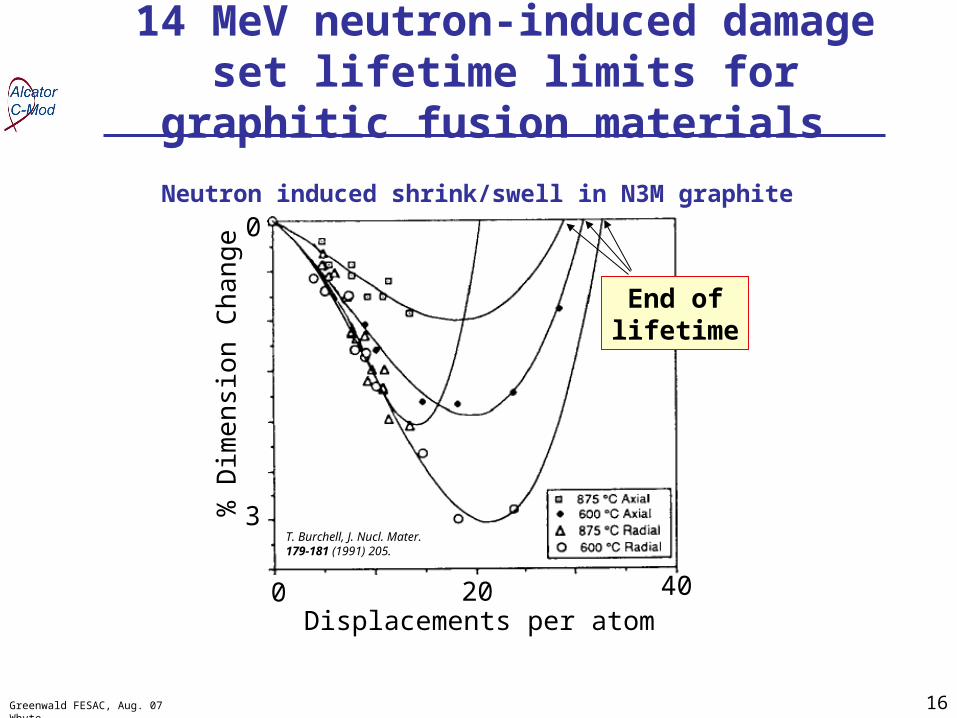
14 MeV neutron-induced damage set lifetime limits for graphitic fusion materials
T. Burchell, J. Nucl. Mater. 179-181 (1991) 205.
Displacements per atom0 20 40
0%
Dim
ensi
on C
hang
e
3
End oflifetime
Neutron induced shrink/swell in N3M graphite


