29
1 HW/SW codesign of a multiple-injections driver for engine control systems Alessandra Nardi Fan Mo Mentor : Alberto Ferrari
| Date post: | 20-Dec-2015 |
| Category: |
Documents |
| View: | 214 times |
| Download: | 0 times |

1
HW/SW codesign of a multiple-injections driver for engine
control systems
Alessandra Nardi
Fan Mo
Mentor : Alberto Ferrari

2
OUTLINE
• Problem definition
• Driver specifications
• Behavioral model
• Functional simulation results

3
PROBLEM DEFINITION - I
• HW/SW Driver for fuel injection
• Direct injection engine– 2 to 4 cylinders
• One injector for every cylinder– independent– max 5 strokes for engine cycle
• Tight time constraints
4
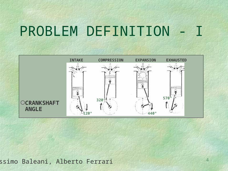
PROBLEM DEFINITION - I
INTAKE COMPRESSION EXPANSION EXHAUSTED
120°
320°
440°
570°
CRANKSHAFT ANGLE
Massimo Baleani, Alberto Ferrari

5
PROBLEM DEFINITION - II
Engine phase Engine angle
0
180
360
540
Exhaust ExplosionCompression Intake
6
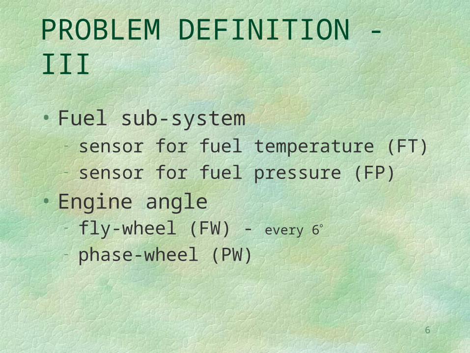
PROBLEM DEFINITION - III
• Fuel sub-system– sensor for fuel temperature (FT)– sensor for fuel pressure (FP)
• Engine angle – fly-wheel (FW) - every 6
– phase-wheel (PW)

7
DRIVER INPUT/OUTPUT
INPUTS
• FW, PW, FT, FP
• Stroke fuel quantities (Q1,…,Q5)
• Stroke opening angles (T1,…,T5)• every TDC Exhaust
PARAMETERS:
Stroke angle ranges : (_o_k, _c_k)
Minimum closure time : Tcmin

8
DRIVER INPUT/OUTPUT
OUTPUTS• Engine angle position (ALPHA90) - every 90
• Engine speed (SRPM90) - every 90
• DC events
• Injector signal J
• Fuel injected in the last cycle: F1, F2, F3, F4, F5
9
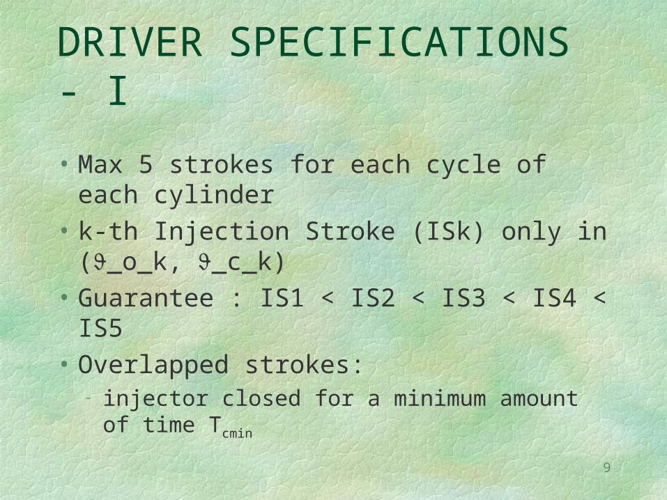
DRIVER SPECIFICATIONS - I
• Max 5 strokes for each cycle of each cylinder
• k-th Injection Stroke (ISk) only in (_o_k, _c_k)
• Guarantee : IS1 < IS2 < IS3 < IS4 < IS5
• Overlapped strokes:– injector closed for a minimum amount of time
Tcmin

10
DRIVER SPECIFICATIONS - II
Tk (_o_k, _c_k) ?
• IF Tk < _o_k
THEN _o_k = _o_k
• IF Tk > _o_k
THEN ISk not scheduled
• IF Tk (_o_k, _c_k)
THEN _o_k = Tk

11
DRIVER SPECIFICATIONS - III
• In case of overlapped strokes:
Minimum Closure Time
IS1
IS1
IS2
IS2

12
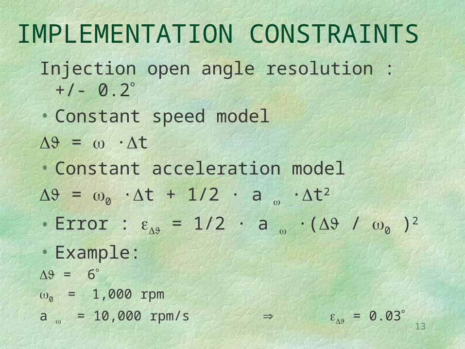
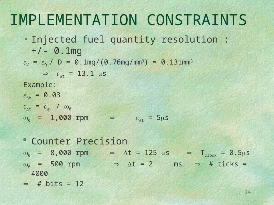
IMPLEMENTATION CONSTRAINTS
• Injection open angle resolution : +/- 0.2• Injected fuel quantity precision : 0.1mg
– if not cut
• All computation must be integer• Only basic mathematical instructions (no sqrt)
• Use IC/OC to implement timed functionality
13
IMPLEMENTATION CONSTRAINTSInjection open angle resolution : +/- 0.2• Constant speed model
= ·t
• Constant acceleration model
= 0 ·t + 1/2 · a ·t2
• Error : = 1/2 · a ·( / 0 )2
• Example: = 60 = 1,000 rpm
a = 10,000 rpm/s = 0.03
14
IMPLEMENTATION CONSTRAINTS• Injected fuel quantity resolution : +/- 0.1mgV = Q / D = 0.1mg/(0.76mg/mm3) = 0.131mm3
t = 13.1 s
Example:
= 0.03
t = / 0
0 = 1,000 rpm t = 5s
Counter Precision0 = 8,000 rpm t = 125 s Tclock = 0.5s
0 = 500 rpm t = 2 ms # ticks = 4000
# bits = 12

15
FUNCTIONAL/ARCHITECTURE CODESIGN
• Behavioral Model– Behavioral Decomposition #1
resources– Behavioral Decomposition #2
resources optimization
16
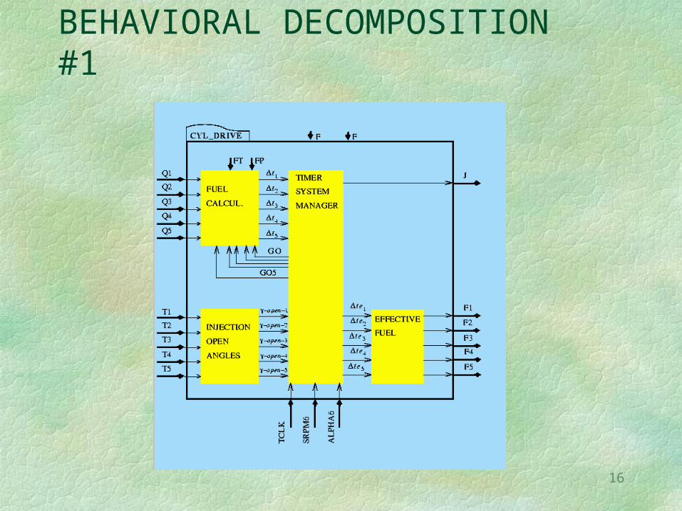
BEHAVIORAL DECOMPOSITION #1

17
BEHAVIORAL DECOMPOSITION #2
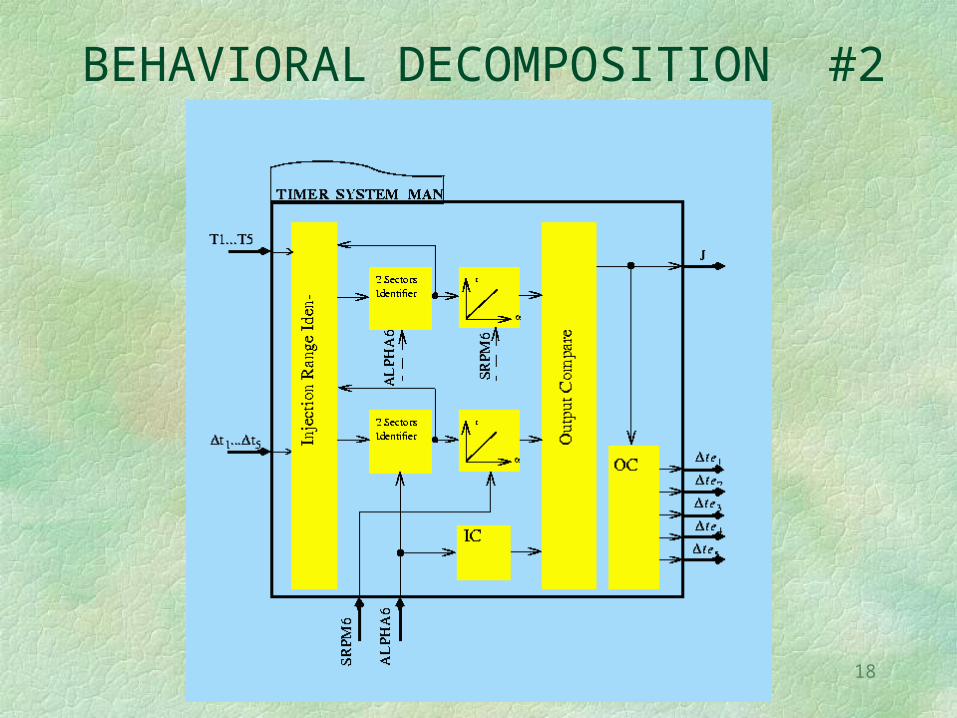
18
BEHAVIORAL DECOMPOSITION #2
19
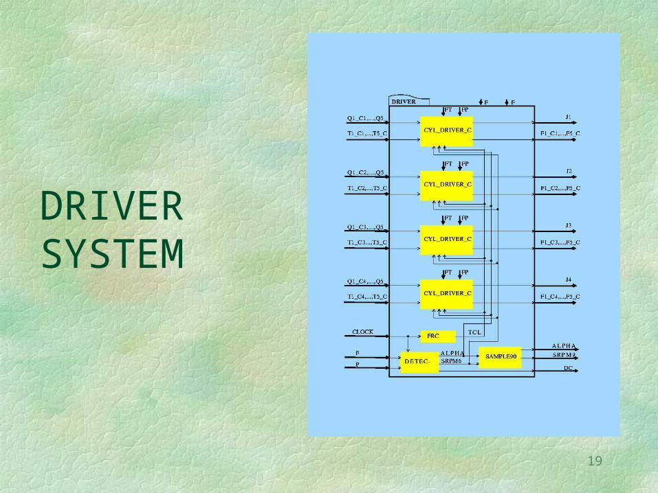
DRIVER SYSTEM
20
ENGINE DETECTION
Description of the modules:
- FRC
- DETECTOR
- SAMPLE90

21
CYLINDER DRIVER

22
CYL_DRIVER/OPEN_INJECTION_ANGLES
Tk (_o_k, _c_k) ?
• IF Tk < _o_k
THEN _o_k = _o_k
• IF Tk > _o_k
THEN Isk not scheduled
• IF Tk (_o_k, _c_k)
THEN _o_k = Tk
23
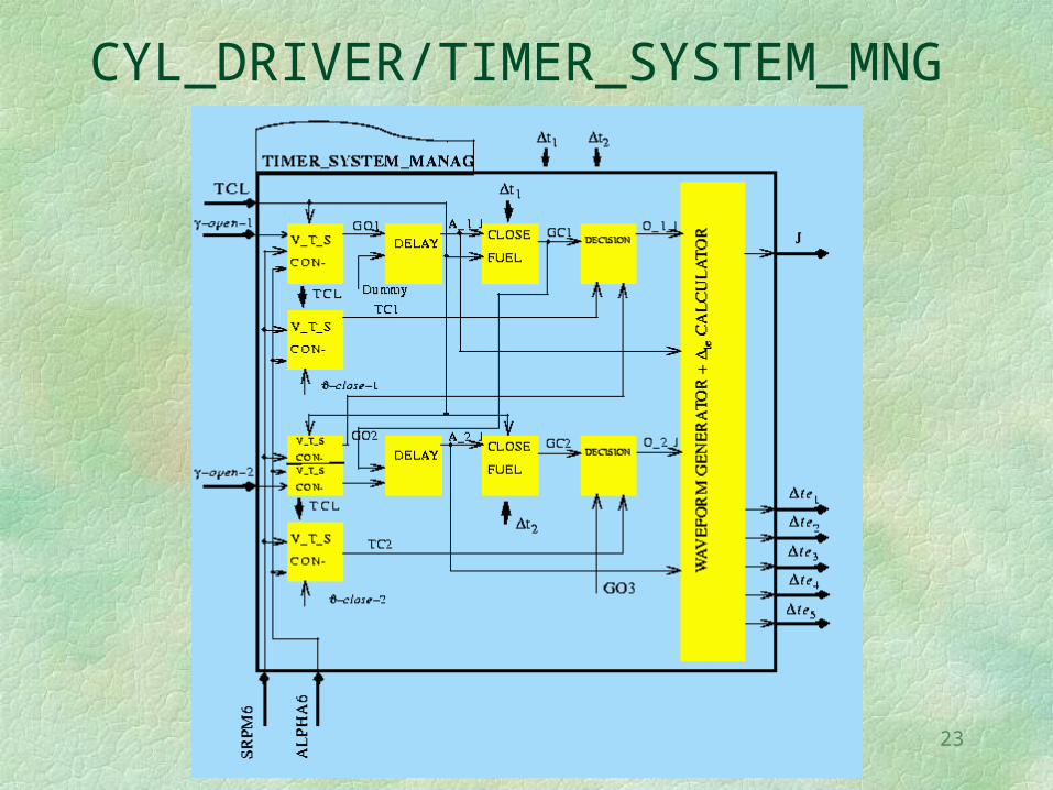
CYL_DRIVER/TIMER_SYSTEM_MNG

24
TIMER_SYSTEM_MNG/V_T_S_CONVERTER
25
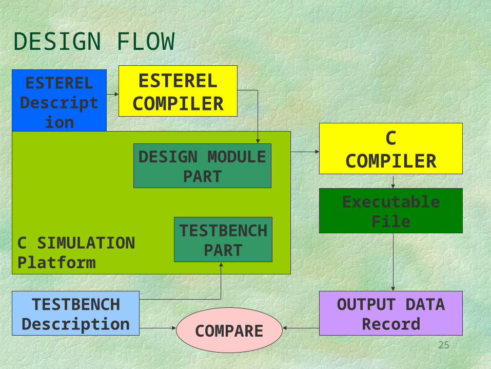
DESIGN FLOW
ESTERELDescription
ESTERELCOMPILER
C SIMULATIONPlatform
TESTBENCHPART
DESIGN MODULEPART
TESTBENCHDescription
CCOMPILER
ExecutableFile
OUTPUT DATARecordCOMPARE

26
SIMULATION RESULTS: RPM
0
1000
2000
3000
4000
5000
6000
7000
8000
0 1000000 2000000 3000000 4000000
Time [s]
Spe
ed [
rpm
]
27
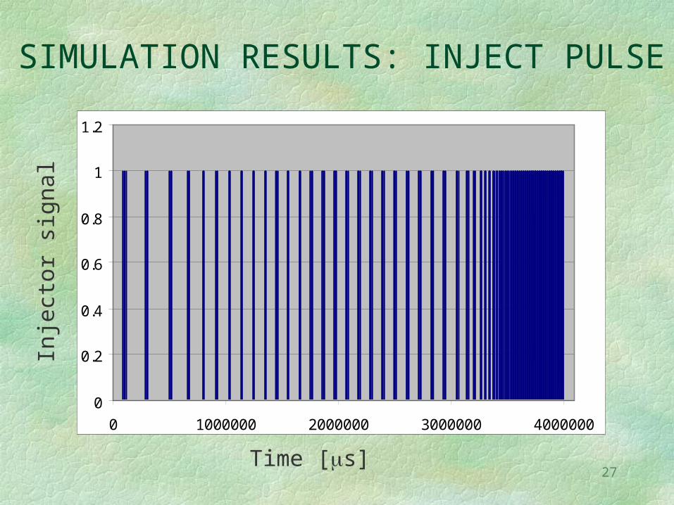
SIMULATION RESULTS: INJECT PULSE
0
0.2
0.4
0.6
0.8
1
1.2
0 1000000 2000000 3000000 4000000
Time [s]
Inje
ctor
sig
nal

28
SIMULATION RESULTS: INJECT PULSE
0
0.2
0.4
0.6
0.8
1
1.2
0 50 100 150
Inje
ctor
sig
nal
Angle [°]
29
PERFORMANCE
- RPM: error < 0.3rov/min
- STROKE: no functional error,
angle error < 0.08 degree
- CLOCK FREQUENCY: 1MHz
(with reference to Testbench provided by Alberto Ferrari)


![EE141 1 Electronic Design Automation [ Adopted from Jan M. Rabaey, Alessandra Nardi, Abhay Dixit, Meeta Bhate, Kedar Rajpathak, Tulika Mitra]](https://static.documents.pub/doc/80x56/56649e155503460f94aff3b7/ee141-1-electronic-design-automation-adopted-from-jan-m-rabaey-alessandra.jpg)


