15
Sunsystem Solar Collector Installation and Operation Manual International Edition 1

Sunsystem
Solar Collector Installation and Operation Manual
International Edition
1

Sunsystem
Content1. Important Information………………………………………………………………..3
2. Unpack and Inspect…………………………………………………………………...5
3. Plumbing…………………………………………………………………………...…..5
4. Stagnation and Overheating…………………………………………………………..6
5. Structure of heat pipe with glass tube…………………………………………..…….7
6. Frame Installation……………………………………………………………………..8
7. Installation collector…………………………………………………….……………11
8. Circuit installation illustration…………………………………...........…………….14
9. Medium liquid filling illustration…………………………………………..………15
10. Medium liquid filling inside the pipeline………………………………………….16
11. Maintenance………………………………………………………………………...17
12. Precautions…………………………………………………………………………..18
2
Sunsystem
1. Important Information 1.1. Local standards
Installation must be completed in accordance with the relevant local standards and regulations. 1.2. Qualified Installer
Installation must be completed by qualified plumbing professionals. 1.3. Pressure and Temperature Control and Relief
a).Solar loop should be designed for normal operation at <600kpa via using a pressure limiting (pressure reduction) value on the main cold supply line. System must be designed to allow pressure release at no more than 800kpa (113psi) and hot water dumping from the solar loop or storage tank once the temperature reaches 99 ℃
b).It is recommended that the lever on the pressure and temperature relief value (PTRV) be operated every 6 months to ensure reliable operation. It is important to raise and lower the lever gently.
1.4. Water quality a).Water in direct flow through the manifold header must firstly meet potable water
requirement and in addition the following: Total dissolved solids ﹤600mg/lire or p.p.m Total hardness ﹤200mg/lire or p.p.m Chloride ﹤250mg/lire or p.p.m Magnesium ﹤10mg/lire or p.p.m b).In areas with hard water (﹥200ppm),lime scale may from inside in heater pipe. In
such regions, it is advisable to install a water softening device to ensure the long term efficient operation of the collector, or use a closed loop for the solar circulation loop.
c). If using a glycol/water must meet the above requirements, and the glycol must be changed periodically to prevent the glycol from becoming acidic. 1.5. Metallic corrosion
a). Both copper & stainless steel are susceptible to corrosion when high concentrations of chloride are present. The solar collector may be used for heating of spa or pool water, but levels of free chorine must not exceed 2p.p.m.
b). In addition the warranty provided on the heater when using for spa or pool heating is 2 years, which is the standard for spa and pool heater. Chloride level present in most reticulated pubic potable water supplies are safe for use in the collector provided there is no use of bore waters in the reticulated supply. 1.6. Freeze protection
Freeze protection should be in corporate into the system by use of a low manifold temperature setting on the solar controller, which turns on the pump if the manifold drops below a preset level (eg.5℃/41℉). Alternatively a closed loop filled with a glycol-water
3
Sunsystem
mix may be used to provide freeze protection. Evacuated tubes are not susceptible to damage in cold weather, and heat pipes are protected against damage caused by freezing of the water inside. 1.7. Hail resistance
a).The glass evacuated tubes are surprising strong and able to handle significant impact stresses once installed. Testing and impact stress modeling proves that the tubes are able to withstand impact from hail up to 25mm/1” in diameter when installed at angle of 40° or greater. The ability of the evacuated tubes to withstand impact from hail is greater influenced by the angle of impact and so installing the collectors at low angles do reduce their impact resistance. However, even when laying flat, impact by hail up to 20mm/3/4” in size will not cause breakage.
b).It is recommended that in areas prone to large hail (>20mm/3/4”) the solar collector should be installed at an angle of 40°or greater to provide optimum protection. As many populated areas in the world fall within the latitude of 30-70° this angel is generally a common installation anyway.
c).If in the unlikely circumstance that a tube should become broken it can be easily in a matter of minutes. The solar collector can still function properly with one or more broken tubes, however a reduction in heat output will result (depending upon how many tube are broken). 1.8. System design and installation
Please read all installation instruction carefully before beginning system design or installation. The system configuration may need to be customized to suit the specific requirements of the installation. Please ensure that any system design meets local building, water quality regulations.
2. Unpack and Inspect 2.1 Transport
When transporting the boxes of the evacuated tube, take notice of the THIS WAY UP arrows. If the boxes can only be laid down, always place on a flat, firm surface such as a compressed wooden board. If stacking the boxes, ideally do not exceed 3 layers, and ensure they are strapped down in place to avoid movement. Straps should be padded with
4
Sunsystem
thick cardboard or similar at box corners to avoid cutting into the box. 2.2 Components list
Please familiarize yourself with the components listed on the packing list, which is included in the collector manifold packing box. If any components missed, or additional parts are required, please contact your supplier who will have parts in store. 2.3 Tube Inspection
Open the tube box (es), which contain both evacuated tubes and heat pipes. Check to make sure the evacuated tubes are all intact and the bottom of each tube is silver. If a tube has a while or clear bottom, it is damaged and should be replaced. Each evacuated tubes contains a pair of metal heat transfer fins .As soon as the evacuated tubes are removed from the box, please put on the rubber tube caps, which are located in the manifold box. This will protect the bottom tip of the glass tube from being broken it knocked .Do not remove and/or expose the tubes to sunlight until you install them, otherwise the inner tube and heat transfer fin will become very hot. The outer glass surface will not become hot. 2.4. Heat pipe If heat pipe are bent during handing, don’t worry as they are not easily damaged. Just ensure they are relatively straight before insertion into the evacuated tube. 2.5. Frame
Unpack the standard frame kit that is packed together with the manifold, if a flat roof frame or low pitched roof frame is being used, shoes components will packed separately from the manifold. It may be necessary to purchase bolts or other fasteners to suit the installation surface. The attachment plates and bolts required to attach the manifold and bottom track are already in place on the frame front tracks. For each frame front track, there are two extra sets of bolts that can be used for securing the roof the roof attachment straps
3. Plumbing
3.1.Plumbing Connection Once the frame has been mounted and the manifold attached, the manifold header
may be connected to the system plumbing. 3.2. Choice of Piping Material
13mm OD, or 15mm OD copper piping is generally used for most solar collector installations. As the flow rate is slow, a large diameter pipe is unnecessary and will only increase system costs and heat loss. Solar collectors come standard with two flexible SS pipe (not in all markets). They are designed for connection to the manifold as they are easy to bend and pass through the roof. The end of the flexible pipe is either 1/2 ℉or 3/4 ℉BSP thread, and so can accept standard male BSP thread fittings for connection to cooper pipe.
5

Sunsystem
3.3. Pressure level Regardless of the installation configuration, pressure release values, expansion
vessels and/or other pressure control devices must be installed. The solar loop should be designed to operate at no more than 800kpa (PRV may be 850 kPa). (800 kPa=8bar=116psi). For installation where mains pressure water is used, the system should ideally be designed to operate at a pressure of <500 kPa, achieved by use of a pressure limiting / reduction value. 3.4 Temperature value.
It is recommended, and may be required by regulations, that a temperature control device (tempering value) be fitted into the hot water pipe between the water heater and bathrooms and en-suites to reduce the risk of scalding. This is achieved by controlling the water temperature to below 50 ℃ /122 ℉ (temperature maybe adjustable). 3.5 Temperature Sensor Insertion
The solar controller’s temperature sensor should be coated with a thick layer of thermal paste and inserted into the sensor port to the full depth. If the fit is too loose, slide a piece of copper plate or wire in beside the sensor. Seal the sensor port opening with silicone sealant to prevent water ingress. Ensure that sensors used on the collector are high temperature rated (up to 250℃/486℉), in particular the cable.
4. Stagnation and Overheating
Stagnation refers to the condition that occurs when the pump stops running, due to pump failure, power blackout, or as a result of a high tank temperature protection feature built into the controller, which turns the pump off. If a PTRV is installed on collector inlet or outlet the collector will continue to increase in temperature until the limit of the temperature relief valves is reached, at which point hot water will be dumped from the system. If a PTRV on the tank will open to release pressure or heat as required. Under such conditions the manifold will normally reach a maximum temperature of around 160℃/320℉. Generally the heat returning from the collector in the form of steam is not enough to affect a continued increase in tank temperature i.e. Heat input < tank heat losses.
Under normal use stagnation should rarely occur as a result of pump stoppage, since Power blackouts normally happen during storms and not clear sunny weather. High tank temperature protection should only occur when hot water is not used for several days (when on holiday), and only during strong periods of sunlight (summer). If leaving the house for an extended period of time ( more than 2-3days), it is advisable to cover the collector panel or design the system with a heat dissipation device or alternative use for the heat, thus preventing overheating of the system and collector stagnation.
Stagnation of the solar collector will NOT damage the solar collector, however insulation used on the piping close to the manifold inlet and outlet should be able to withstand temperatures of up to 200℃/395 ℉ (E.g. Glass wool or mineral wool-with an
6

Sunsystem
exterior wrap of aluminum foil, thus protecting against the elements).
5. Structure of heat pipe with glass Tube
The heat pipe series solar collector are always connected with existing heating supply device. The selective coating on the inner cover of the evacuated tubes converts solar energy into heat energy and transfers heat to the heat pipes by aluminum fins. The liquid in the heat pipe changes into vapor which rises to the condenser. The heat then passes through the heat exchanger and the vapor becomes liquid , returning to the base of the heat pipe. The heat conducts to the heat transfer liquid(anti-freezing liquid or water )via a copper pipe. This transference of heat into the liquid creates a continuous circulation as long as the collector is heated by the sun.
Feature: Can operate with water pressure up to 0.6Mpa can be combined with existing energy source storage do not need be installed above the collector.
6. Frame Installation
6.1. Frame Material All frame components are made of 2.0 mm thickness Aluminum Alloy make the
frame both strong and corrosion resistant. It is important that the frame attachment
7

Sunsystem
points and externally supplied fasteners are also of suitable structural strength. 6.2 Installation Please refer the following steps. 1 a) Install on the flat roof 1 b)Install Install on the slope roof2
Choose the brackets “Z hook” as the support. Install front track , bottom tracks on the above fixed brackets( Z hooks ) as
right top figure then put bottom track on front tracks end as right bottom figure.
7. Installation collector
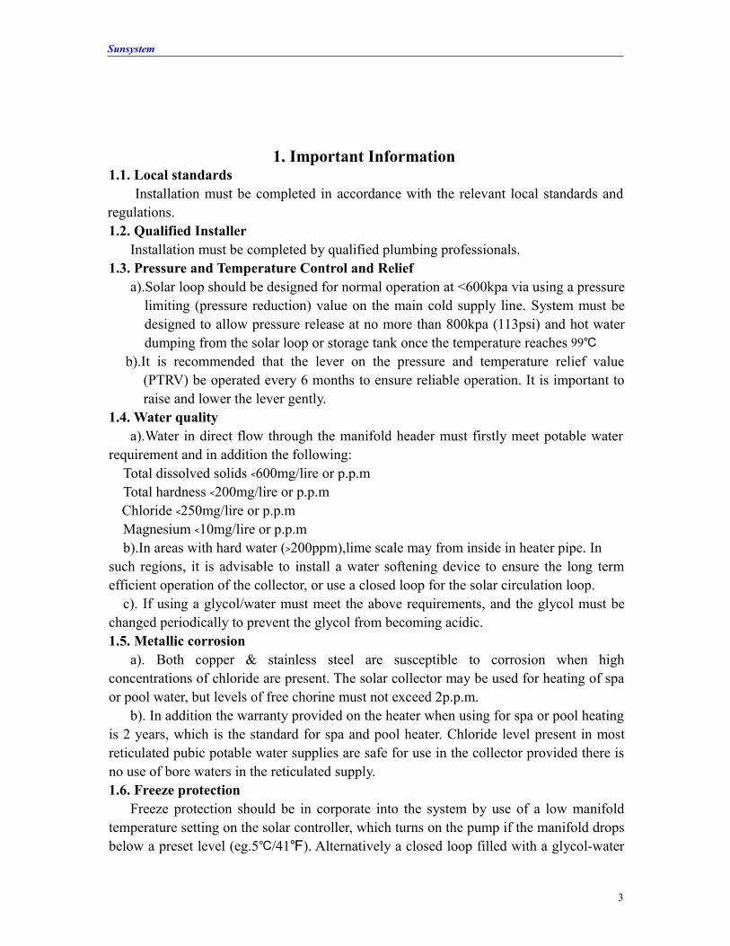
7.1 Manifold Material The outer shell of the Manifold is made of 2.0 mm thickness Aluminum Alloy. We
used the Rock-wool as the insulation material and the Flow Passage is the TU Copper.
8
Sunsystem
7.2 Lighting Protection It is advisable to earth / ground the copper circulation loop of the collector to avoid
lighting related damage. 7.3 Collector direction
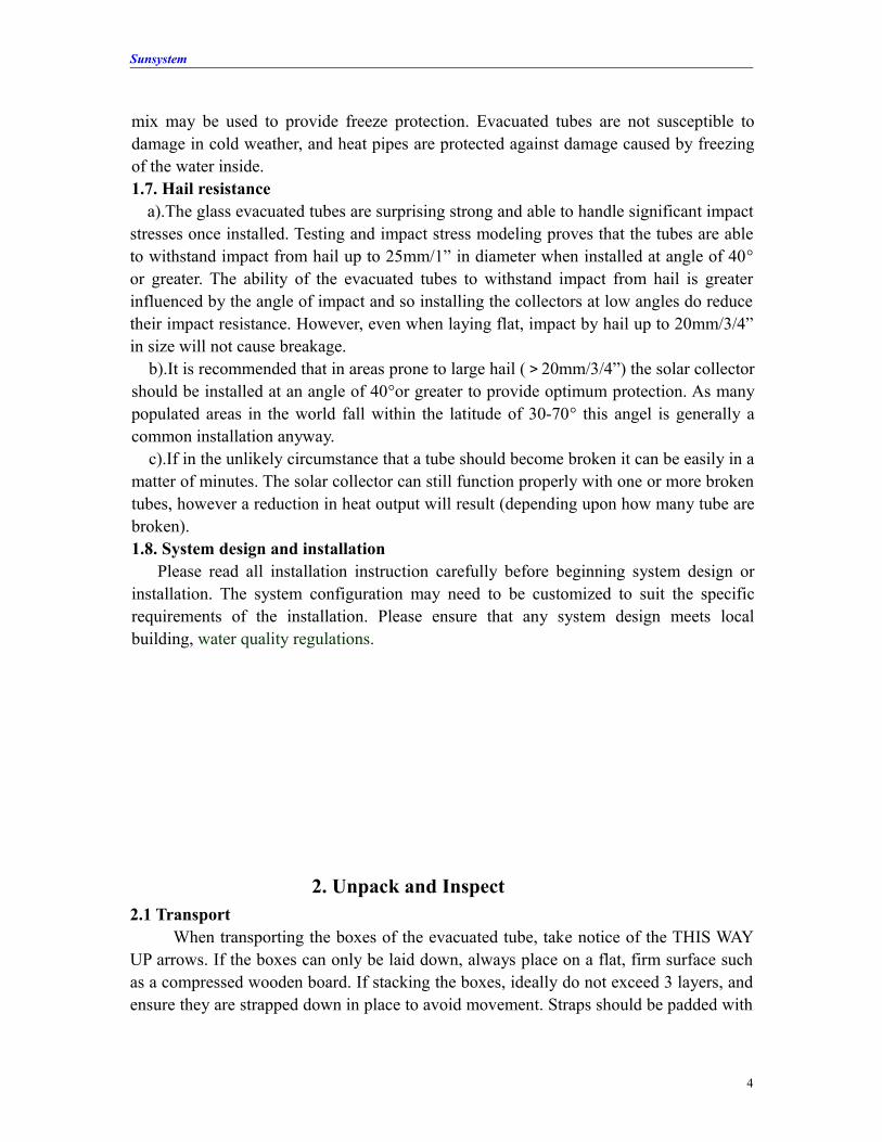
The collector should face the equator, which if in the northern hemisphere is due south, and vice versa, Facing the collector in the correct direction and at the correct angle is important to ensure optimal heat output from the collector, however a deviation of up to 10 from due north or south is acceptable, and will have minimal effect on heat output. 7.4 Location
The collector should be positioned as close as possible to the storage cylinder to avoid long pipe runs. Storage cylinder positioning should therefore consider the location requirements of the solar collector. The storage cylinder should also be located as close as possible to the most frequent draw off pipe runs.
9

Step1: First install the nylon cap on the bottom track, and then screw off the jacket from the nylon cap.
Step2: Put the anti-dust rubber ring on the vacuum tube (mild dish washing liquid & water will be very useful). Then paint the heat conduction resin on the heat pipe condenser.
Step3: Insert the vacuum tube inside the nylon cap. (Be careful: don’t touch the vacuum tube on the ground, or it will be broken.)
Step4: Hold the vacuum tube tightly, then insert it inside the opposite hole which on the manifold slowly.
Step 5: Screw the jacket on the nylon cap. 7.5 Pipe connections a) Connection to the inlet and outlet may be use of brass compression fittings (with copper olive) , or low temperature soldering. b) For domestic heating application with 2 collectors or less, nominal 15mm/(1/2” )pipe is suitable. c) For applications using 2 or more solar collectors in series, it is advisable to use a nominal 20mm/(3/4”) piping.
7.6 Connection of Multiple collectors of 20 ㎡
When connecting collectors in series, flexible connections should be used between each collector, in order to allow for expansion and contraction of the copper header with temperature changes .Failure to use flexible connection between consecutive collectors may result in damage to the header if the system stagnates.
10
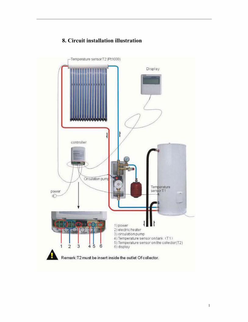
8. Circuit installation illustration
11

9. Medium liquid filling illustration
10. Medium liquid filling inside the pipeline: Pure Water 56% and Original Anti-freezing liquid: 44%
12
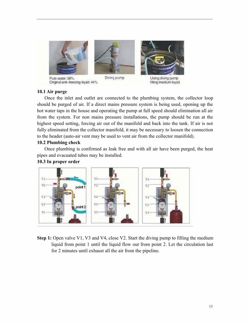
10.1 Air purge Once the inlet and outlet are connected to the plumbing system, the collector loop
should be purged of air. If a direct mains pressure system is being used, opening up the hot water taps in the house and operating the pump at full speed should elimination all air from the system. For non mains pressure installations, the pump should be run at the highest speed setting, forcing air out of the manifold and back into the tank. If air is not fully eliminated from the collector manifold, it may be necessary to loosen the connection to the header (auto-air vent may be used to vent air from the collector manifold). 10.2 Plumbing check
Once plumbing is confirmed as leak free and with all air have been purged, the heat pipes and evacuated tubes may be installed. 10.3 In proper order
Step 1: Open valve V1, V3 and V4, close V2. Start the diving pump to filling the medium liquid from point 1 until the liquid flow out from point 2. Let the circulation last for 2 minutes until exhaust all the air from the pipeline.
13
Step 2: Close the valve V3, then close the V1 and take off the diving pump. Step 3: Connect the expansion vessel on V3, open the valve V3 and V2 for the valve
V4, it must be open forever. Starting the working station, observing the balancing Valve (V5) to see if there is any air inside the pipeline. If there is air inside the
pipeline, fill medium liquid again as the above steps until exhaust the all the air.
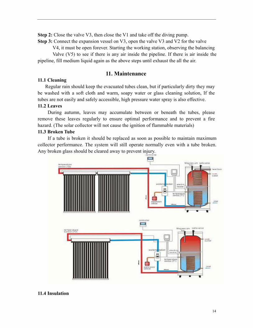
11. Maintenance 11.1 Cleaning
Regular rain should keep the evacuated tubes clean, but if particularly dirty they may be washed with a soft cloth and warm, soapy water or glass cleaning solution, If the tubes are not easily and safely accessible, high pressure water spray is also effective. 11.2 Leaves
During autumn, leaves may accumulate between or beneath the tubes, please remove these leaves regularly to ensure optimal performance and to prevent a fire hazard. (The solar collector will not cause the ignition of flammable materials) 11.3 Broken Tube
If a tube is broken it should be replaced as soon as possible to maintain maximum collector performance. The system will still operate normally even with a tube broken. Any broken glass should be cleared away to prevent injury.
11.4 Insulation
14
The plumbing pipes running to and from the collector should be heavily insulated. This insulation foam should be checked annually for damage. For any insulation that is exposed to sunlight UV stabilized foam.
12. Precautions
12.1 Solar for central heating-preventing Overheating If a system has been designed to provide contribution to central heating, it will
often provide much more heat in the summer than is required for hot water supply alone. In such cases it is advisable for the home to have a sap or pool that can use the heat in the summer period or a heat dissipation device be installed. 12.2 Metallic components
Always wear glove when handing the various solar collector components. All efforts have been made to make the metal components safe to handle, but there may still be some shape edges. 12.3 Evacuated tubes
Be careful when handing the evacuated tubes, as they will break if knocked heavily or dropped. Wear gloves if handing any broken glass.
12.4 Wind and Snow Load a). When install the collector , please consider the issue of wind resistance. The Standard frame and all frame kits are designed to withstand wind speeds of up to 208km/h. b). In areas prone to heavy snow falls the solar collector should ideally be installed at an angel of 50 degree or greater to help promote snow sliding off the tube. In addition it is advisable to raise the front of the front collector frame 15-20mm off the roof surface as this allows snow to sit beneath the collector and also more easily blow away from under the collector. 12.5 High temperatures
With the heat pipe installed in the evacuated tube, and good sunlight, the heat pipe condenser can reach temperatures in excess of 200 /℃ 392℉. At this temperature touch the heat pipe will result in serious burns, so please take care when experimenting with or “demonstrating” the evacuated tube and heat pipes, in an installed, fully plumbed system, if the pump is stopped during good sunlight, the collector header and plumbing pipe close to the manifold can reach temperatures of 160 / ℃ 320℉, and therefore caution should be taken when touching such components.
15


