3rd Micro and Nano Flows Conference Thessaloniki, Greece, 22-24 August 2011 An Experimental Investigation on Friction Characteristics of Air Flow in Microtube with Structured Surface Roughness Ting-Yu Lin 2 , Chia-Wei Chen 1 , Chien-Yuh Yang 1* and Satish G., Kandlikar 2 * Corresponding author: Tel.: +886 (3)426 7355; Fax: +886 (3)425 4501; Email: [email protected]1: National Central University, Jhong-Li, Taoyuan, Taiwan 2: Rochester Institute of Technology, Rochester, New York, USA Abstract Experiments were conducted in this research to investigate roughness effect to flow characteristics and heat transfer coefficient of air and CO 2 flow in circular micro-tubes. The internal surface of tested tube included smooth, structure helical fin surfaces and random roughness surfaces. Smooth tube is a commercial S. S. 304 tube with internal diameter of 962 µm and average roughness Ra=0.8 µm, while rough circular tubes were lab made Nickel tube with diameters ranging from 926 µm to 977 µm and roughness elements from 5.3 µm to 44.6 µm in height. The experimental results indicated that f and Nu in smooth tube was predicted very well by conventional correlations both for air and CO 2 . In rough tubes the friction factor was significant higher than the prediction of conventional correlations both in laminar and turbulent flow. Heat transfer enhancement in laminar flow is slightly, nevertheless, in turbulent flow the heat transfer enhancement was significant and the enhancement increases with the increasing of Re. The random rough tubes revealed a higher heat transfer enhancement than the structured helical fin tubes. Keywords: Roughness effects, flow characteristics, heat transfer coefficient, micro-tubes, Nickel, CO 2 , Air 1. Introduction Heat transfer and flow characteristics studies in microchannels had been widely increasing due to the development of MEMS technology and the application in micro heat exchanger, fuel cell, biomedical chip etc. Fundamental research in microchannels is essential to the design and development in products. Many earlier research in literature revealed heat transfer and flow characteristics data in microchannels departure from the prediction of conventional correlations for smooth channels (Peiyi and Little (1983); Lin et al. (1991); Mala and Li (1999); Cheng and Wu (2003); Cheng and Wu (2003); Phares and Smedley (2004)). For liquid flow in circular smooth microtubes, friction factor and heat transfer coefficient was found to agree well with conventional correlations (Judy et al. (2002); Yen et al. (2003); Lelea et al. (2004); Lin and Yang (2007); Yang and Lin (2007)). The data sets were found to be predicted well by conventional correlation with diameter higher than 15 µm (Judy et al. 2002) for friction factor and 123 µm (Yang and Lin 2007) for Nusselt number. Kandlikar et al. (2005) , Brackbill and Kandlikar (2007), Brackbill and Kandlikar (2010) systematically investigated the effect of structured roughness to friction factor in rectangular microchannels with different structured surface roughness. Their data showed in smooth channel f was in good agreement with conventional correlation while in rough channel f was significant higher than the smooth channel correlations. A modified hydraulic diameter was defined for using in rough channel. Previous research has also study roughness effect of gas flow in microchannels. The friction factor in 45-83 µm channel was greater than conventional correlation in both laminar and turbulent flow (Peiyi and Little (1983). While in friction factor in smooth channel was founded to be in good agreement with the prediction of smooth channel correlation(Tang et al. (2007), however, in - 1 -
Transcript
3rd Micro and Nano Flows Conference Thessaloniki, Greece, 22-24 August 2011
An Experimental Investigation on Friction Characteristics of Air Flow in Microtube with
Structured Surface Roughness
Ting-Yu Lin2, Chia-Wei Chen1, Chien-Yuh Yang1* and Satish G., Kandlikar2
1: National Central University, Jhong-Li, Taoyuan, Taiwan 2: Rochester Institute of Technology, Rochester, New York, USA
Abstract Experiments were conducted in this research to investigate roughness effect to flow characteristics and heat transfer coefficient of air and CO2 flow in circular micro-tubes. The internal surface of tested tube included smooth, structure helical fin surfaces and random roughness surfaces. Smooth tube is a commercial S. S. 304 tube with internal diameter of 962 µm and average roughness Ra=0.8 µm, while rough circular tubes were lab made Nickel tube with diameters ranging from 926 µm to 977 µm and roughness elements from 5.3 µm to 44.6 µm in height. The experimental results indicated that f and Nu in smooth tube was predicted very well by conventional correlations both for air and CO2. In rough tubes the friction factor was significant higher than the prediction of conventional correlations both in laminar and turbulent flow. Heat transfer enhancement in laminar flow is slightly, nevertheless, in turbulent flow the heat transfer enhancement was significant and the enhancement increases with the increasing of Re. The random rough tubes revealed a higher heat transfer enhancement than the structured helical fin tubes. Keywords: Roughness effects, flow characteristics, heat transfer coefficient, micro-tubes, Nickel, CO2, Air 1. Introduction Heat transfer and flow characteristics studies in microchannels had been widely increasing due to the development of MEMS technology and the application in micro heat exchanger, fuel cell, biomedical chip etc. Fundamental research in microchannels is essential to the design and development in products. Many earlier research in literature revealed heat transfer and flow characteristics data in microchannels departure from the prediction of conventional correlations for smooth channels (Peiyi and Little (1983); Lin et al. (1991); Mala and Li (1999); Cheng and Wu (2003); Cheng and Wu (2003); Phares and Smedley (2004)). For liquid flow in circular smooth microtubes, friction factor and heat transfer coefficient was found to agree well with conventional correlations (Judy et al. (2002); Yen et al. (2003); Lelea et al. (2004); Lin and Yang (2007); Yang and Lin (2007)). The data sets were found to be predicted well by conventional correlation with diameter
higher than 15 µm (Judy et al. 2002) for friction factor and 123 µm (Yang and Lin 2007) for Nusselt number. Kandlikar et al. (2005) , Brackbill and Kandlikar (2007), Brackbill and Kandlikar (2010) systematically investigated the effect of structured roughness to friction factor in rectangular microchannels with different structured surface roughness. Their data showed in smooth channel f was in good agreement with conventional correlation while in rough channel f was significant higher than the smooth channel correlations. A modified hydraulic diameter was defined for using in rough channel. Previous research has also study roughness effect of gas flow in microchannels. The friction factor in 45-83 µm channel was greater than conventional correlation in both laminar and turbulent flow (Peiyi and Little (1983). While in friction factor in smooth channel was founded to be in good agreement with the prediction of smooth channel correlation(Tang et al. (2007), however, in
3rd Micro and Nano Flows Conference Thessaloniki, Greece, 22-24 August 2011
rough tubes the friction factor was higher than the prediction of smooth channel correlations. Circular tube with different internal surface roughness was made in Kandlikar et al. (2003) by acid treatment, the Ra/di changed from 0.36 % to 0.16 % for 0.62mm tube and 0.18% to 0.28% for 1.067 mm tube. Heat transfer enhancement due to roughness was observed in their research. Heat transfer enhancement in both laminar and turbulent flows has been an area of great interest for quite a long time (Webb 1992). In macroscale laminar flow, some of the enhancement techniques receiving renewed interest are: twisted tubes (Krishna et al. (2009); Wongcharee and Eiamsa-ard (2011)), porous materials (Huang et al. (2010)), and coiled wires (Akhavan-Behabadi et al. 2010). In turbulent flow, enhanced structure on channel internal walls was investigated and found to enhance heat transfer. Pethkool et al. (2011) investigated heat transfer enhancement in helically corrugated tube. Their data showed that the effect of relative roughness was higher than the effect of pitch. There is very limited data available for studying systematic effect of enhancement techniques on heat transfer and pressure drop. Very few researches investigated heat transfer of gas flow in microchannel due to the difficulties in experiments. This research aimed to make roughness structure on internal surface of circular tube. Furthermore, the flow characteristics and heat transfer performance of gas flow in these tubes were tested. Experiments of smooth tube in the same diameter range with rough tube were also performed in order to compare the effect of roughness to friction factor and Nu. Process of rough tubes making and experimental results of friction factor and Nusselt number were discussed in detail. 2. Experimental set up Figure 1 shows a schematic drawing of the experimental setup. Air and CO2 bottles were used to offer fluid flowing through tube. Flow meters with different working ranges were used to measure the flow rate. Test section was
installed in vacuum chamber to decrease the natural convection heat loss. Thermocouples are attached on the tube wall to measure the wall temperatures. Tube was directly Joule heating through power supply. The experimental set up is the same as the research of (see the paper submitted to Journal Lin and Kandlikar [2011]).
Fig. 1 Schematic drawing of the experimental setup
Test section Surface treatment of substratum To produce different internal rough surfaces tubes, the fabrication process included 4 part as illustrated in Fig. 2: (a) The chosen of Substratum (b) Rough structure making (c) Nickel layer depositing and (d) Erasing of substratum. The details are described as follows:
Fig.2 Process steps for the fabrication of rough tubes making (a) Substratum tube (b) Rough structure making on the tube (c) Nickel layer
depositing (d) Erasing of substratum
(a) Substratum tube: An inner and outer diameter of 0.5 mm and 1 mm aluminum tube has been chosen for its characteristics in easy to be machined and etched. (b) Rough structure making on the tube: Structured and random rough surfaces were first generated on the external surface of aluminum tube. (c) Nickel layer depositing:
- 2 -
3rd Micro and Nano Flows Conference Thessaloniki, Greece, 22-24 August 2011
Nickel was chosen to form a tube due to its relative high electricity resistance, high hardness and high strength. Erasing of substratum: (d) Erasing of substratum: 50 oC NaOH solutions with 10% concentration was used to erase the aluminum substratum. A tube with internal rough surface was obtained after etching the aluminum substratum. The external surface of aluminum substratum after treatment was evaluated by a laser co focal microscope as shown in Fig. 3. (a)-(d). Figure 3 (a) and (b) show the rough surfaces generated by directly scraping aluminum tube through sandpaper #50 and #120. The measured Ra values of the surface were 9.3 m and 5.6 m , respectively. While a uniform and structured surface was generated by the machining of circular dies and helical fins surface tube was formed as shown in Fig. 3 (c). The depth and pitch of fins are 45 µm and 220 µm. Another helical fins type was created by chemical etching. An aluminum substratum wrapped by PTFE tape then etched by NaOH. Wrapped Grooves were formed on the substratum surface without wrapping the PTFE tape, and hence helical fins were generated shown as Fig. 3(d). The fin depth and pitch are 96 µm and 1.9 mm respectively.
Fig3. External surface of aluminum
substratum (a) Tube B generated by sandpaper#50 (b)
Tube C generated by sandpaper#120 (c) Tube D generated by circular dies (d) Tube E
generated by NaOH etching In this research the thickness was designed
about 120 µm based on the consideration of strength and electric resistance. The cross section image of aluminum tube with nickel deposited on it and the rough tube after erasing aluminum substratum is shown in Fig. 4. Nickel layer was uniformly deposited on aluminum tube and a circular Nickel tube with designed internal surface was formed.
Fig4. Cross section of the deposit tube (a) with aluminum substratum (b) after erasing substratum Internal surfaces profile of nickel tube Figure 5 shows the internal surfaces profile of test tubes presented in the form of true image, 3-D contour and center line profile. The tubes were cut open and image was taken and analyzed by a laser co focal microscope. Fig. 5 (a) is the commercial smooth stainless steel 304 tube termed as Tube A, the Ra of this tube is about 0.8 µm. Figs. 5(b)-(e) are lab made Nickel tubes. Fig. 5(b) and 5(c) were the rough tubes termed Tube B and Tube C which were generated from the substratum treated by sand paper #50 and #120, respectively. Fig. 5 (d) and (e) were the rough tubes termed Tube D and Tube E which were generated from the substratum treated by circular dies and PTFE tape with chemical etching.
(a) Tube A (smooth)
- 3 -
3rd Micro and Nano Flows Conference Thessaloniki, Greece, 22-24 August 2011
(b) Tube B (Rc=18.7 µm)
(c) Tube C (Rc=5.3 µm)
(d) Tube D (Rc=13.2 µm, Pitch=0.22mm)
(e) Tube E (Rc=44.6 µm, Pitch=1.90mm)
Fig. 5 Internal surface profile of test tubes
In the present study the internal surface roughness in the Nickel tube is complicated due to the non-uniform roughness elements. Instead of using Ra, the roughness level was represent by Rc in the present study. Where Rc is the mean value of the profile element heights with a sampling length defined as follows:
Where are the element heights as
shown in Fig. 6.
Fig. 6 Mean value of the profile element
heights with a sampling length (JIS B 0601: 2001)
The characteristics of test tubes in the present study were shown in Table 1, includes: surface condition of substratum, tools to machine substratum, diameters, heating length and internal surface condition of test tubes.
Table1. Detailed of the test tubes in the present
study A: smooth, B: Random rough (#50 sandpaper),
C: Random rough (#120 sandpaper), D: Helical fins (dies), E: Helical fins (PTFE tape)
. Results
.1 Friction factor ressibility of air and CO2
p
3 3 Due to the compap arent friction factor was calculated from the correlation give by Shapiro [1953] as following:
Where , , , , , and are the hydraulic diamet , e len , specific gas constant, fluid temperature, mass flux, inlet and outlet pressure of tubes. Figure 7 shows friction factor as a function of Re for CO
er tub gth
2 and air flow in 962 µm smooth tube. It is observed that the friction factor data of CO2 and air are the same and can be predicted very
- 4 -
3rd Micro and Nano Flows Conference Thessaloniki, Greece, 22-24 August 2011
well by conventional correlation both in laminar and turbulent flow. The transition Re is about 2000 which is similar with that of fluid flow in macro scale tubes.
Fig. 7 Friction factor plotted as a function of
is
Re for CO2 and air flow in smooth tube
In smooth tube the internal diameter usually used as characteristics length. However in rough tube the definition of tube diameter will effects the friction factor and heat transfer data. By considering the effect of cross section area reduction due to protruding roughness elements, constricted diameter dcf defined by (Kandlikar, Schmitt et al. 2005) was used to represent hydraulic diameter as the following:
Figure 8 shows the comparison of friction c
fa tor of Tube E by defining hydraulic diameter as di and dcf. The data show a better agreement with the conventional correlation by using dcf as hydraulic diameter.
Fig. 8 The comparison of f by using different
The com luids is as
definition of hydraulic diameter for Tube E
(Helical, Rc=44.6 µm)
parison of different fshown in Fig. 9 (a) and (b). There is no significant difference of f for CO2 and air flow in tubes. All the rough tube data revealed f significant higher than the prediction of conventional correlation. While the smooth tube data was in good agreement with conventional correlation.
(a)
(b)
Fig. 9 Friction factor ll tubes in (a) air (b)
3.2 Heat Transfer Coefficient and Nu are
of aCO2
Heat transfer coefficient hcalculated from the following correlation:
Where is heat flux, is wall temperature measured by thermo ples, cou is the local fluid temperature calculated from energy balance. Due to the low fluid heat capacity and small tube diameter in the present study, input heat is too lower to neglect the
- 5 -
3rd Micro and Nano Flows Conference Thessaloniki, Greece, 22-24 August 2011
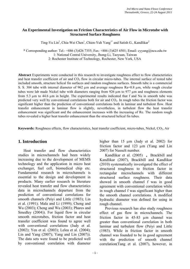
effect of heat loss, axial conduction and viscous heating. Detailed data reduction of friction factor and heat transfer coefficient can be found from the research of the paper submitted to Journal by Lin and Kandlikar [2011]. Figure 10 shows the comparison Nu for air and CO2 flow in smooth tube. Both air and CO2 data sets revealed that the Nu can be predicted well by conventional correlation.
Fig. 10 Heat transfer coefficient and Nu for air
Figure 11 shows the Nu of air and CO2 in
and CO2 flow in smooth tube
Tube D in different heating length compare to conventional correlations. There data is very less dependent on heating length. In laminar flow, Nu is slightly higher than smooth channel theoretical prediction. In turbulent flow, Nu is higher than prediction with Re higher than 10,000. In turbulent flow with Re from 3,000 to 10,000 no heat transfer enhancement was observed.
Fig. 11 Nu of Tube D as a function of Re
for a
re 12 shows all the Nu data of air and
O
ir and CO2 Figu
C 2 in all tubes in laminar flow. The Nu approached to the prediction of smooth tube correlations. In higher Re the Nu is slightly higher than conventional correlation. This is due to developing flow effects. The experimental data concluded that there is no significant heat transfer enhancement in laminar flow. There is no significant difference among all the test tubes in the present study.
Fig. 12 Nu of air and CO2 flow in all test tubes
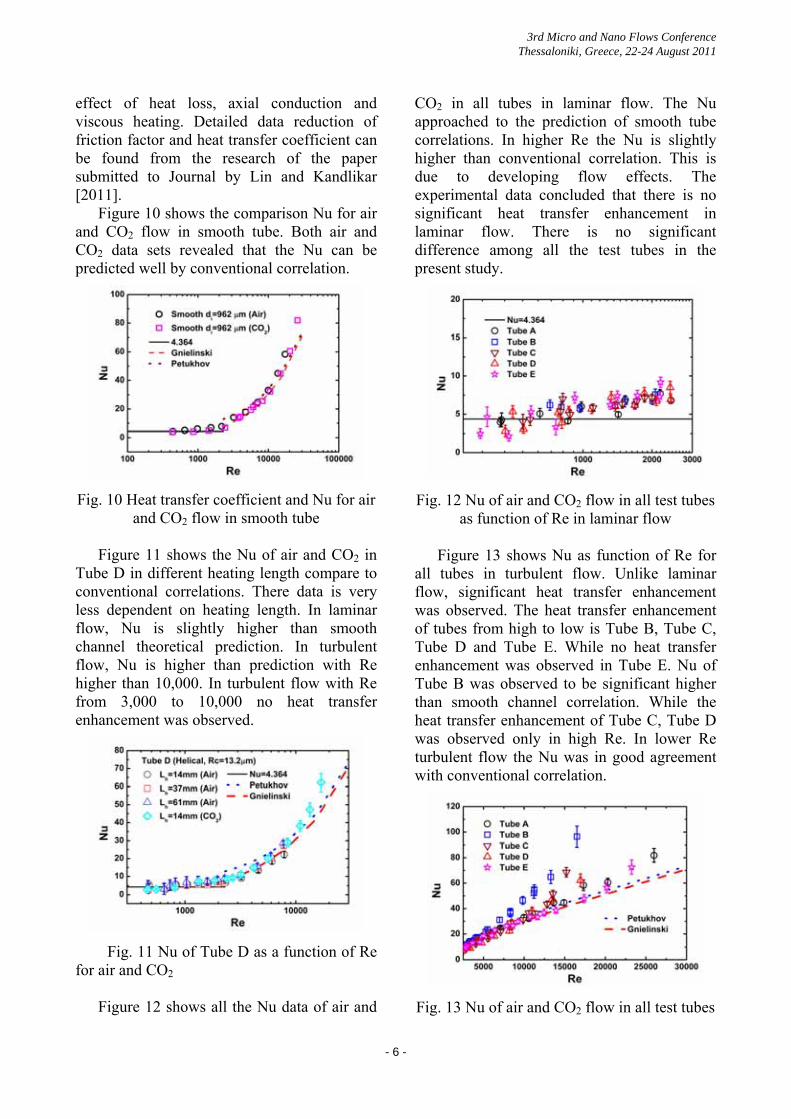
Figure 13 shows Nu as function of Re for
as function of Re in laminar flow
all tubes in turbulent flow. Unlike laminar flow, significant heat transfer enhancement was observed. The heat transfer enhancement of tubes from high to low is Tube B, Tube C, Tube D and Tube E. While no heat transfer enhancement was observed in Tube E. Nu of Tube B was observed to be significant higher than smooth channel correlation. While the heat transfer enhancement of Tube C, Tube D was observed only in high Re. In lower Re turbulent flow the Nu was in good agreement with conventional correlation.
Fig. 13 Nu of air and CO2 flow in all test tubes
- 6 -
3rd Micro and Nano Flows Conference Thessaloniki, Greece, 22-24 August 2011
as function of Re in turbulent flow
4. Conclusions
with 4 different rough surface
omenclature
ted diameter, m
nsionless H Helical fin height, m
of fluid, W/m
Heating length of tube, m imensionless
t
dimensionless ss, m
re, oC re, oC
n-Behabadi, M. A., Kumar, R., . R., Azimi, R., 2010, Pressure
drop
ghness on press
on of lubrication theory and study
y of convective heat transfer in si
l silicon micr
Enhancing heat
Nickel tubes structure was successfully made in the present study. Flow characteristics and heat transfer performance of air and CO2 flow in tubes were studied. Flow characteristics and heat transfer performance in a smooth stainless steel tube in the same diameter range was also revealed to compare with the data in rough tubes. Friction factor and Nusselts number in smooth data was in a very good agreement with conventional correlations in laminar and turbulent flow. While friction factor in roughness tubes were higher than the prediction of conventional correlation derived from macro scale smooth tube both in laminar and turbulent flow. Heat transfer coefficient in laminar flow agrees with the conventional correlation, the heat transfer enhancement is slightly. In turbulent flow, heat transfer enhancement was observed clearly. The enhancement increases with the increasing of Re. By comparing the Nu in different rough tubes, it was observed that the heat transfer coefficient data of rough tubes from high to low are Tube B (random rough structure, Rc=18.7 µm), Tube C (random rough structure, Rc=5.3 µm), Tube D (helical fins structure, Rc=13.2 µm, pitch=0.22 mm) and Tube E (helical fins structure, Rc=44.6 µm, pitch=1.90 mm). Nu of Tube E was predicted well by conventional correlations for smooth tube. No heat transfer enhancement was observed. While the other rough tubes revealed a significant heat transfer enhancement phenomenon and the enhancement increased with Re. More studies are needed to identify the effects of surface rough to flow characteristics and heat transfer performance in tubes. N
dcf constricdh Hydraulic diameter, m di Internal diameter, m f Fanning friction factor, dime
h Heat transfer coefficient, W/m2 oC kf Thermal conductivityoCL Length, m Lh Nu Nusselt number, dP Helical fin pitch,m Pin Inlet pressure, Pa Pou Outlet pressure, Pa ∆P Pressure drop, Pa q” Heat flux, W/m2
Re Reynolds number, Ra Average roughneRc Roughness, m T Temperature, oC Tf,x Local fluid temperatuTw,x Local wall temperatu References
AkhavaSalimpour, M
and heat transfer augmentation due to coiled wire inserts during laminar flow of oil inside a horizontal tube. International Journal of Thermal Sciences 49, 373-379.
Brackbill, T. P. and Kandlikar, S. G., 2007, Effect of sawtooth rou
ure drop and turbulent transition in microchannels. Heat Transfer Engineering 28 (8-9), 662-669.
Brackbill, T. P. and Kandlikar, S. G., 2010, Applicati
of roughness pitch during laminar, transition, and low reynolds number turbulent flow at microscale. Heat Transfer Engineering 31 (8), 635-645.
Cheng, P. and Wu, H. Y., 2003, An experimental stud
licon microchannels with different surface conditions. International Journal of Heat and Mass Transfer 46 (14), 2547-2556.
Cheng, P. and Wu, H. Y., 2003, Friction factors in smooth trapezoida
ochannels with different aspect ratios. International Journal of Heat and Mass Transfer 46 (14), 2519-2525.
Huang, Z. F., Nakayama, A., Yang, K., Yang, C., Liu, W., 2010,
- 7 -
3rd Micro and Nano Flows Conference Thessaloniki, Greece, 22-24 August 2011
trans
for liqui
on heat transfer and
rization of surfa
9, Heat transfer and press
icrotube heat transfer and fluid flow of distilled water.
cal frictional press
on forced conv
ion Effects During Single-Phase Flow in
tics of water in microtubes.
Inter
g, S., Promvonge, P., 2011, Turb
ar liquids through circu
ics of compressible fluid flow, vol.
tudy of compressibility, roughness and rarefaction influences on
ed heat transfer. New York, John Wiley & So
and heat transfer characteristics of lami
of Friction Factors for the Flow of G
water flow in micr
boiling heat transfer in m
fer in the core flow by using porous medium insert in a tube. International Journal of Heat and Mass Transfer 53, 1164-1174.
Judy, J., Maynes, D., Webb, B. W., 2002, Characterization of frictional pressure drop
d flows through microchannels. International Journal of Heat and Mass Transfer 45 (17), 3477-3489.
Kandlikar, S. G., Joshi, S., Tian, S., 2003, Effect of surface roughness
fluid flow characteristics at low Reynolds numbers in small diameter tubes. Heat Transfer Engineering 24 (3), 4-16.
Kandlikar, S. G., Schmitt, D., Carrano A. S., Taylor, J. B., 2005, Characte
ce roughness effects on pressure drop in single-phase flow in minichannels. Physics of Fluids 17 (10): 100606.
Krishna, S. R., Pathipaka, G., Sivashanmugam, P., 200
ure drop studies in a circular tube fitted with straight full twist. Experimental Thermal and Fluid Science 33, 431-438.
Lelea, D., Nishio, S., Takano, K., 2004, The experimental research on m
International Journal of Heat and Mass Transfer 47 (12-13), 2817-2830.
Lin, S., Kwok, C. C. K., Li, R. Y., Chen, Z. H., Chen, Z. Y., 1991, Lo
ure drop during vaporization of R-12 through capillary tubes. International Journal of Multiphase Flow 17, 95-102.
Lin, T.-Y. and C.-Y. Yang, 2007, An experimental investigation
ection heat transfer performance in micro tubes by the method of liquid crystal thermography. International Journal of Heat and Mass Transfer 50 (23-24), 4736-4742.
Lin, T.-Y. and Kandlikar, S. G., 2011, "A Theoretical Model for Axial Heat Conduct
Microchannels." Submitted to Journal of Heat Transfer.
Mala, G. M. and D. Li , 1999, Flow characteris
national Journal of Heat and Fluid Flow 20, 142-148.
Pethkool, S., Eiamsa-ard, S., Kwankaomen
ulent heat transfer enhancement in a heat exchanger using helically corrugated tube. International Communications in Heat and Mass Transfer 38: 340-347.
Phares, D. J. and Smedley, G. T., 2004, A study of laminar flow of pol
lar microtubes. Physics of Fluids 16, 1267-1272.
Shapiro, A.K., 1953. The dynamics and thermodynam
1-2. Jhon Wiley.
Tang, G. H., Li, Z., He, Y. L., Tao, E. Q., 2007, Experimental s
microchannel flow. International Journal of Heat and Mass Transfer 50 (11-12), 2282-2295.
Webb, R. L., 1992, Principles of enhanc
ns.
Wongcharee, K. and Eiamsa-ard, S., 2011, Friction
nar swirl flow through the round tubes inserted with alternate clockwise and counter-clockwise twisted-tapes. International Communications in Heat and Mass Transfer 38, 348-352.
Wu, P. and Little, W. A., 1983, Measurement
ases in Very Fine Channels Used for Microminiature Joule-Thomson Refrigerators. Cryogenics 23 (5), 273-277.
Yang, C.-Y. and Lin, T.-Y., 2007, Heat transfer characteristics of
otubes. Experimental Thermal and Fluid Science 32 (2), 432-439.