77
Dr. S.H. Upadhyay Mechanical & Industrial Engineering Deptt. IIT Roorkee
| Date post: | 20-Oct-2015 |
| Category: |
Documents |
| Upload: | jeewan-atwal |
| View: | 168 times |
| Download: | 2 times |
Dr. S.H. UpadhyayMechanical & Industrial Engineering Deptt.
IIT Roorkee

CWS-25; MTE-25; ETE-501.Introduction to mechatronics and mechatronics
approach; measurement system; control systems;microprocessor based controllers.
2.Sensors and transducers:Performance terminology;photoelectric transducers; flow transducers; opticalsensors and transducers; semiconductor lasers,selection of sensors, mechanical/electricalswitches, inputting data by switches.
3.Actuators and mechanisms: Actuation systems;pneumatic and hydraulic systems; process controlvalves; rotary actuators; mechanical actuationsystems; electrical actuation systems
2

4. Signal conditioning: Signal conditioning; filteringdigital signals; Multiplexers; Data acquisition;Digital signal processing; Pulse modulation; dataPresentation systems.
5. Microprocessors and microcontrollers: Control;microcomputer structure; Microcontrollers;applications; programmable logic controllers.
6. Modeling & system response: Mathematicalmodels; Mechanical, electrical, hydraulic andthermal Systems; Dynamic response of systems;Transfer function and frequency response; closedloop controllers; MATLAB as development tool.
7. Design and Mechatronics: Input/output system;Computer based modular design; Systemvalidation; Remote monitoring and control;Designing; Possible design solutions; Case studies.
3

Mechatronics: Bolton, W., Longman Introduction to Mechatronics: D.G.Alciatore & Michael B. Histand; TataMc Graw Hill
Mechatronic system Design; ShettyDedas, Kolk and Richard
Mechatronic handbook: Bishop; CRCpress
4

5
“The name [mechatronics] was coined by Ko Kikuchi, now
president of Yasakawa Electric Co., Chiyoda-Ku, Tokyo.”
“The word, mechatronics is composed of mecha from mechanics
and tronics from electronics. In other words, technologies and
developed products will be incorporating electronics more and
more into mechanisms, intimately and organically, and making it
impossible to tell where one ends and the other begins.”
Mechatronics
mecha
tronicsEletronics
Mechanics

Harashima, Tomizuka, and Fukada, 1996
“Synergistic integration of mechanical engineering with
electronics and intelligent computer control in the design and
manufacturing of industrial products and processes.”
Auslander and Kempf, 1996
◦ Mechatronics is the application of complex decision making
to the operation of physical systems.
6

Shetty and Kolk in 1997“Mechatronics is a methodology used for the optimal designof electromechanical products.”
W. Bolton, 1995
“Integration of electronics, control engineering, andmechanical engineering.”
S. Ashley, 1997“Synergistic use of precision engineering, control theory,
computer science, and sensor and actuator technology todesign improved products and processes.”
7

D. G. Alciatore and M. B. Histand,1998
“Field of study involving the analysis, design, synthesis, and
selection of systems that combine electronics and mechanical
components with modern controls and microprocessors.”
Mechatronics is generally
◦ recognized worldwide as a vibrant area of study.◦ Undergraduate and graduate programs in mechatronic
engineering are now offered in many universities.◦ Refereed journals are being published and dedicated
conferences are being organized and are generally highlyattended.
8

Implementing electronics control in a mechanical system.
Enhancing existing mechanical design with intelligent control.
Replacing mechanical component with a electronic solution.
9

Mechanical Engineering
Electrical Engineering
Computer Engineering
Computer/Information Systems
10
Information
Systems
Electrical
Systems
Computer
Systems
Mechanical
Systems
Mechatrnoics

The need
Analysis of problem
Preparation of Specification
Generation of possible solutions
Selection of a suitable solution
Production of a detailed design
Production of working drawings
11

TRADITIONAL DESIGN: The temperature control for adomestic central heating system has been the bi-metallicthermostat of a closed loop control system. The bending ofbi-metallic strip changes as the temperature changes and isused to operate an on/off switch for the heating system.
The bi-metallic thermostat is comparatively crude andthe temperature is not accurately controlled; alsodevising a method for having different temperatures atdifferent times of the day is complex and not easilyachieved.
12

MECHATRONIC DESIGN: A mechatronic solution to theproblem might be to use a microprocessor controlledsystem employing perhaps a thermo-diode as the sensor
The microprocessor-controlled system can, however,cope easily with giving precision and programmedcontrol. The system is much more flexible. Thisimprovement in flexibility is a common characteristicof mechotronics systems when compared withtraditional systems.
13

14
Real life applications:
THERMOSTAT
TRADITIONAL DESIGN MECHATRONICS DESIGN

15
TRADITIONAL THERMOSTAT DESIGNTRADITIONAL THERMOSTAT DESIGN
SECTIONAL VIEW COMPONENTS OF THERMOSTAT

16
CONVERSION TO MECHATRONIC DESIGNCONVERSION TO MECHATRONIC DESIGN

17
A PICKA PICK--ANDAND--PLACE ROBOT PLACE ROBOT The basic form of a Pick-and-Place robot unit is
shown in the Figure (a).
The robot has three axes, about which the motioncan occur i.e. rotation in a clockwise or counterclockwise direction of the unit on its base, armextension or contraction and arm up and down; alsothe gripper can open and close.
These movements can be actuated by the use ofpneumatic cylinders operated by solenoid-controlledvalves with limit switches to indicate when a motionis completed.
Thus the clockwise rotation of the unit might resultfrom the piston in a linear cylinder being extendedand the counter clockwise direction by its retraction.Likewise the upward movement of the arm mightresult from the piston in a linear cylinder beingextended and the downward motion from itretracting; the extension of the arm by the piston inanother cylinder extending and its return movementby the piston retracting.
The gripper can be opened or closed by the piston ina linear cylinder extending or retracting. Figure (b)shows a basic mechanism that could be used
Figure (a)
Figure (b)

18
MECHATRONICS SOLUTIONMECHATRONICS SOLUTION Figure below shows how a micro controller could be used to
control the solenoid valves and hence the movements of the
robot unit.

19
CAR PARK BARRIERS CAR PARK BARRIERS As an illustration of a PLC, consider the
coin-operated barriers for a car park.
The in-barrier is to open when thecorrect money is inserted in thecollection box and the out-barrier is toopen when a car is detected at the carpark side of the barrier.
The Figure shows the types of valvesystems that can be used to lift andlower the pivoted barriers.
When a current flows through thesolenoid of valve A, the piston in acylinder moves upwards and causes thebarrier to rotate about its pivot and raiseto a let a car through. When the currentthrough solenoid of valve A ceases, thereturn spring of the valve results in thevalve position changing back to itsoriginal position.
When the current is switched to throughthe solenoid of valve B the pressure isapplied to lower the barrier. Limitswitches are used to detect when thebarrier is down and also when fully up.

20
MECHATRONICS SOLUTIONMECHATRONICS SOLUTION
PLC connections Ladder diagram

21
ADVANTAGES OF MECHATRONICS DESIGNADVANTAGES OF MECHATRONICS DESIGN
HIGH RESOLUTION & ACCURACY
REDUCES HOUSE HOLD HEATING COST
SELF CALIBRATING
FLEXIBLE DESIGN
ENVIRONMENTAL FRIENDLY

In the late 1970s, the Japan Society for the Promotion ofMachine Industry (JSPMI) classified mechatronic productsinto
Class I:◦ Primarily mechanical products with electronics
incorporated to enhance functionality.◦ Examples include numerically controlled machine tools and
variable speed drives in manufacturing machines. Class II:
◦ Traditional mechanical systems with significantly updatedinternal devices incorporating electronics. The external userinterfaces are unaltered.
◦ Examples include the modern sewing machine andautomated manufacturing systems.
22

Class III:◦ Systems that retain the functionality of the traditional
mechanical system, but the internal mechanisms arereplaced by electronics.
◦ An example is the digital watch. Class IV:
◦ Products designed with mechanical and electronictechnologies through synergistic integration.
◦ Examples include photocopiers, intelligent washers anddryers, and automatic ovens.
23

The enable technologies for each mechatronic product classillustrate the progression of electromechanical products instride with developments in control theory, computationtechnologies, and microprocessors.
ClassClass II productsproducts were enabled by servo technology, powerelectronics, and control theory.
ClassClass IIII productsproducts were enabled by the availability of earlycomputational and memory devices and custom circuit designcapabilities.
ClassClass IIIIII productsproducts relied heavily on the microprocessor andintegrated circuits to replace mechanical systems.
ClassClass IVIV productsproducts marked the beginning of true mechatronicsystems, through integration of mechanical systems andelectronics.
24

It was not until the 1970s with the development of themicroprocessor by the Intel Corporation thatintegration of computational systems with mechanicalsystems became practical.
The electronic ignition system was one of the firstmechatronic systems to be introduced in theautomobile in the late 1970s.
25

In several technical areas the integration of products or
processes and electronics can be observed.
This is especially true for mechanical systems which
developed since about 1980.
These systems changed from electro-mechanical systems with
discrete electrical and mechanical parts to integrated
electronic-mechanical systems with sensors, actuators, and
digital microelectronics.
These integrated systems, as seen in Table are called
mechatronic systems , with the connection of MECHAnics and
elecTRONICS.
26

All these definitions agree that mechatronics is an
interdisciplinary field , in which the following
disciplines act together (see Figure)
mechanical systems (mechanical elements, machines,
precision mechanics);
electronic systems (microelectronics, power
electronics, sensor and actuator technology); and
information technology (systems theory, automation,
software engineering, artificial intelligence).
27

28

29
Mechatronics: synergetic integration of different disciplines.

Some modern mechanical process like a powerproducing or a power generating machine. A primaryenergy flows into the machine and is then either directlyused for the energy consumer in the case of an energytransformer, or converted into another energy form inthe case of an energy converter.
The form of energy can be electrical, mechanical(potential or kinetic, hydraulic, pneumatic), chemical,or thermal. Machines are mostly characterized by acontinuous or periodic (repetitive) energy flow.
For other mechanical processes, such as mechanicalelements or precision mechanical devices, piecewise orintermittent energy flows are typical.
30

31
Mechanical process and information
processing develop towards mechatronic
systems.

Division of Functions between Mechanics and
Electronics
Improvement of Operating Properties
Addition of New Functions
32
General scheme of a (classical) mechanical-electronic system.

•More features•Higher precession•User friendly•More flexible•Lower cost, Efficient•Environment friendly.•Smaller geometry.•More reliable.•Safer
33

34

Above figure illustrates all the components ina typical mechatronic system.
The actuators produce motion or cause someaction.
The sensors detect the state of the systemparameters, input, and output; digital devicescontrol the system;
Conditioning and interfacing circuits provideconnections between the control circuits andinput/output devices and
Graphical display provide visual feedback tousers.
35
36
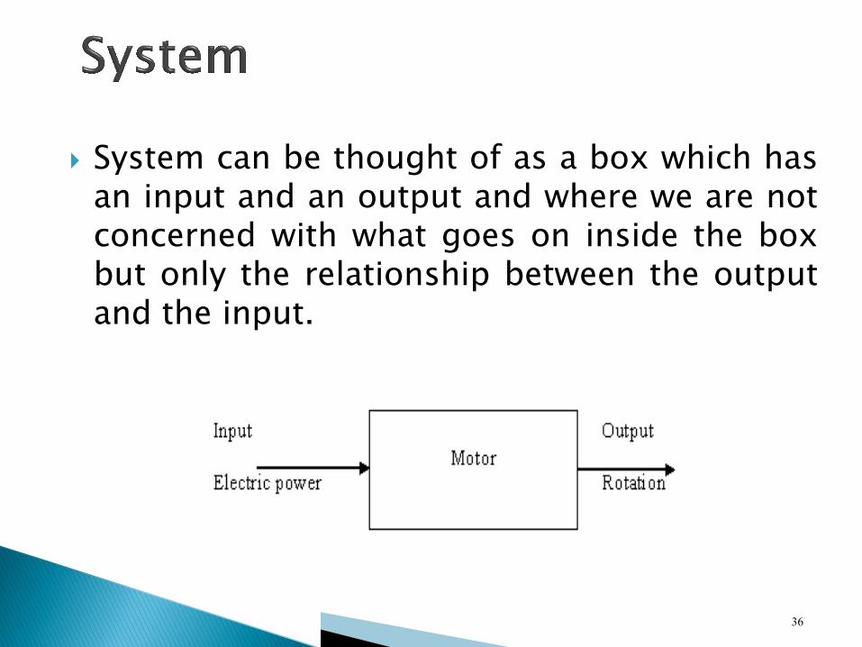
System can be thought of as a box which hasan input and an output and where we are notconcerned with what goes on inside the boxbut only the relationship between the outputand the input.

A fundamental part of many mechatronic system is a
measurement system composed of the three basic parts shown
in fig.
The transducer is a sensing device that converts a physical
input into an output, usually a voltage.
The signal processor performs filtering, amplification, or other
signal conditioning on the transducer output.
The term sensor is often used to refer to the transducer or to
the combination of transducer and signal processor.
Finally recorder is an instrument, a computer, a hard-copy
device or simply a display that maintains the sensor data for
online monitoring or subsequent processing.
37

38
Signal processorTransducer Recorder
Elements of a measurement system

A black box used for making measurements.
It has the input the quantity being measured and output the value of the quantity.
Example: temperature measurement system
39
Input
TemperatureThermometer
Output
Number on
a scale
An example of a measurement system

The given figure is also another example of ameasurement system.
The thermocouple is a transducer thatconverts temperature to a small voltage.
The amplifier increases the magnitude of thevoltage; the A/D (analog-to-digital) converteris a device that changes the analog signal to acoded digital signal;
The LED (light emitting diodes) display thevalue of the temperature.
40

signal conditioner display
41

A control system can be thought of as a black box
which is used to control its output to some particular
value or particular sequence of value.
For example, a domestic central heating control
system has as its input the temperature required in
the house and as its output the house at the
temperature.
i.e set the required temperature on the thermostat or
controller and the heating furnace adjusts itself to
pump water through radiators and so produce the
required temperature in the house.
42

43
Central Heating System
Input
Required
temperature
Output
Temper
ature of
the set
value

Open loop systems
Closed loop systems
44

45
Switch Electric fireInput
Decisi
on to
switch
on or
off
Electric
power
Output
Temper
ature
change
Open Loop SystemOpen Loop System

46
Input
Requir
ed
temper
ature
Switch Electric fire
Electric
power
Output
A
constant
tempera
ture
Measuring
device
-
+Comparison element
Deviation
signal
Feedback of temperature signal

47
Controlled
variable
Refer
ence
value
Control unitCorrection
unit
Measuring
device
-
+Comparison element
Error
signal
Measured value
Process

Comparison element◦ This compares the required or reference value of
the variable condition being controlled with themeasured value of what is being achieved andproduces and error signal. It can be regarded asadding the reference signal, which is positive, tothe measured value signal, which is negative in thiscase:
Error signal= reference value signal – measured valuesignal
Control element◦ This decides what action to take when it receives an
error signal.
48

Correction element◦ The correction element produces a change in the
process to correct or change the controlledcondition.
◦ Thus it might be a switch which switches on aheater and so increase the temperature of theprocess or a valve which opens and allows moreliquid to enter the process.
Process element◦ The process is what is being controlled.
◦ It could be a room in a house with temperaturebeing controlled or a tank of water with its levelbeing controlled.
Measurement element◦ The measurement element produces a signal
related to the variable condition of the process thatis being controlled.
49

Controlled variable - the room temperature
Reference value - the required room temperature
Comparison element -the person comparing themeasured value with the requiredvalue of the temperature
Error signal -the difference between themeasured and requiredtemperatures
Control unit -the person
Correction unit -the switch on the fire
Measuring device - a thermometer
50

51

The digital integrated circuit (IC) called amicroprocessors [Figure].
This revolution has occurred because themicroprocessor brings the flexibility ofprogram control and thecomputational power of a computer to bearon any problem.
Microprocessors are now rapidly replacingthe mechanical cam-operated controllersand being used in general to carry outcontrol functions.
52

53

In many simple systems there might be justan embedded microcontroller, this being amicroprocessor with memory all integratedon one chip, which has been specificallyprogrammed for the task concerned.
microprocessor-based control systems arerapidly replacing many older control systemsbased on analog circuits or electromechanicalrelays
One of the first microprocessor-basecontrollers made specifically for controlapplications was the programmable logiccontroller (PLC).
54

This is a microprocessor-based controllerwhich used programmable memory to storeinstructions and to implement functionssuch as logic, sequence, timing countingand arithmetic to control events and can bereadily reprogrammed for different tasks.
A microprocessor by itself is not a computer;additional components such as memory andinput/output circuits are required to make itoperational
55

56
OutputsInputs
A
Controller
Control program
B
D
C
P
Q
R
S
Programmable logic controller

However, the microcontroller Figure, which is aclose relative of the microprocessor, does containall the computer functions on a single IC,
Microcontroller lack some of the power and speedof the newer microprocessors, but theircompactness is ideal for many control applications;most so-called microprocessor controlled devices,such as vending machines, are really usingmicrocontrollers.
57

58

Some specific reasons for using a digital, microprocessrdesign in control systems are the following:
◦ Low level signals from sensors once converted todigital, can be transmitted long distances virtuallyerror-free.
◦ A microprocessor can easily handle complexcalculations and control strategies.
◦ Long term memory is available to keep track ofparameters in slow moving system.
◦ Changing the control strategy is easy by loading in anew program; no hardware changes are required.
◦ Microprocessor-base controllers are more easilyconnected to the computer network within anorganization. This allows designer to enter programchanges and read current system status from theirdesk terminals.
59

When buying or ordering an MBC the following is a step bystep procedure to simplify the process.
◦ 1. Specify Digital Inputs - List the Digital inputs and theirvoltage ranges.
◦ 2. Specify Analog Inputs - List the Analog inputs and theirvoltage swings.
◦ 3. Specify Data Inputs - List any Data inputs.
◦ 4. Specify On/Off Outputs - List On/Off outputs and theircurrent ratings.
◦ 5. Specify Proportional Outputs - List Proportional outputsand their current ratings.
◦ 6. Specify Data Outputs - List the Data outputs.
◦ 7. Describe the desired MBC operation. Describe anymonitoring, limiting or automation to be done by the MBC
60

62

63
Spark timing
Air Fuel Mixture Solenoid
Fuel injection valve
Engine speed
Crankshaft position
Spark timing feedback
Engine temperature
Throttle position
Mass air flow
Micro
processor

64

It has Analog and digital circuits, sensors,actuators, and microprocessors.
Working◦ User places an original in a loading bin and pushes a
button to start the process.◦ The original is transported to the platen glass◦ A high intensity light source scans the original and
transfers the corresponding image as a chargedistribution to a drum.
◦ Blank piece of paper is retrieved from loadingcartridge, and image is transferred onto the paperwith an electrostatic deposition of ink toner powderthat is heated to bond to the paper.
◦ A sorting mechanism then delivers the copy to anappropriate bin.
65

Control◦ Analogue circuits control the lamp, heater, and other power
circuit.◦ Digital circuit controls digital display, indicator lights,
buttons, switches forming the user interface.◦ Other digital ckt include logic ckts and microprocessor that
coordinates all the functions of the machine.
Sensors◦ Optical sensors and micro switches detect the presence on
absence of paper, its proper positioning, and whether ornot door and latches are in proper position.
◦ Encoders used to track motor rotation.
Actuators ◦ (servo/stepper) load and transport the paper, turn the drum
and index the drum.
66

67

68

69

70

71

72

Actuators◦ Servo Motors
Sensors◦ IR Sensor for obstruction detection◦ Bumper Sensor for obstruction detection◦ Compass, for orientation detection◦ Accelerometer, for tilt detection◦ Ultrasonic sensor, for range detection.
Micro Controller◦ BASIC Stamp 2 module
73

Growth in mechatronic systems will be fueled by thegrowth in the constituent areas.
Advancements in traditional disciplines fuel the growthof mechatronics systems by providing “enablingtechnologies.”
For example, the invention of the microprocessor hada profound effect on the redesign of mechanicalsystems and design of new mechatronics systems.
We should expect continued advancements in cost-effective microprocessors and microcontrollers, sensorand actuator development enabled by advancements inapplications of MEMS, adaptive control methodologiesand real-time programming methods, networking andwireless technologies, mature CAE technologies foradvanced system modeling, virtual prototyping, andtesting.
74
The continued rapid development in these areas willonly accelerate the pace of smart product development.
The Internet is a technology that, when utilized incombination with wireless technology, may also lead tonew mechatronic products.
While developments in automotives provide brightexamples of mechatronics development, there arenumerous examples of intelligent systems in all walksof life, including smart home appliances such asdishwashers, vacuum cleaners, microwaves, andwireless network enabled devices.
In the area of “human-friendly machines” we canexpect advances in robot-assisted surgery, andimplantable sensors and actuators.
Other areas that will benefit from mechatronic advancesmay include robotics, manufacturing, space technology,and transportation.
The future of mechatronics is wide open.
75

Mechatronic system designs are complex by nature, andare becoming more complex day by day.
As the system design grow in overall size toaccommodate ever increasing demands for functionalityand performance, these design must integrate analogand digital hardware, as well as the software thatcontrols them.
Mechatronic system’s behavior is determined byinterdependencies between different components.
Therefore, an integrated and interdisciplinaryengineering approach is necessary.
For this reason, engineers must be assisted by toolswhich allow a systems analysis with respect tocapabilities, capacities and behavior without reallyconstructing the system.
This necessitates an appropriate modeling andsimulation tool for mechatronic systems.
76

77


