45
Schlumberger Private Schlumberger Private Introduction to Nodal Analysis Advanced Artificial Lift for Production Solutions and Optimization Engineers Presented by Jeff Kain
| Date post: | 21-Dec-2015 |
| Category: |
Documents |
| Upload: | martin-udan |
| View: | 39 times |
| Download: | 1 times |

Sch
lum
berg
er P
rivate
Sch
lum
berg
er P
rivate
Introduction to Nodal Analysis
Advanced Artificial Lift for Production Solutions and
Optimization Engineers
Presented by Jeff Kain

Sch
lum
berg
er P
rivate
Sch
lum
berg
er P
rivate
Objectives
• Understand the components of Inflow performance
• Understand the components of vertical lift performance
• Understand combining inflow and vertical lift performance
• Describe the Pressure versus depth relationship for different lift methods

Sch
lum
berg
er P
rivate
Sch
lum
berg
er P
rivate
Pressure Losses
Pe
_
PrPwfsPwf
Pdr
Pur
Pusv
Pdsv
Pwh
Pdsc Psep
DP1 = Pr - Pwfs = Loss in Porous MediumDP2 = Pwfs - Pwf = Loss across CompletionDP3 = Pur - Pdr = Loss across RestrictionDP4 = Pusv - Pdsv = Loss across Safety ValveDP5 = Pwh - Pdsc = Loss across Surface ChokeDP6 = Pdsc - Psep = Loss in Flowline
DP7 = Pwf - Pwh = Total Loss in TubingDP8 = Pwh - Psep = Total Loss in Flowline
Possible Pressure Losses in Complete Production System
Bottom
HoleRestriction
SafetyValve
Surface
Choke
Separator

Sch
lum
berg
er P
rivate
Sch
lum
berg
er P
rivate
INJECTION GAS
PRODUCED FLUID
WELL
INFLOW (IPR)
WELL OUTFLOW
RELATIONSHIP
(VLP) or (TPC)
SURFACE PRESSURE
SANDFACE PRESSURE
BHFP
RESERVOIR PRESSURE
BOTTOM HOLE PRESSURE AS A FUNCTION OF FLOWRATEBOTTOM HOLE PRESSURE AS A FUNCTION OF FLOWRATE
PRODUCTION POTENTIAL AS A FUNCTION OF PRODUCTION RATEPRODUCTION POTENTIAL AS A FUNCTION OF PRODUCTION RATE

Sch
lum
berg
er P
rivate
Sch
lum
berg
er P
rivate
Pe
_
PrPwfsPwf
Pdr
Pur
Pusv
Pdsv
Pwh
Pdsc Psep
DP1 = Pr - Pwfs = Loss in Porous MediumDP2 = Pwfs - Pwf = Loss across CompletionDP3 = Pur - Pdr = Loss across RestrictionDP4 = Pusv - Pdsv = Loss across Safety ValveDP5 = Pwh - Pdsc = Loss across Surface ChokeDP6 = Pdsc - Psep = Loss in Flowline
DP7 = Pwf - Pwh = Total Loss in TubingDP8 = Pwh - Psep = Total Loss in Flowline
Possible Pressure Losses in Complete Production System
Bottom
Hole
Restriction
SafetyValve
SurfaceChoke
Separator

Sch
lum
berg
er P
rivate
Sch
lum
berg
er P
rivate
Inflow Performance Curve
0
500
1000
1500
2000
2500
3000
3500
0 500 1000 1500 2000 2500 3000 3500 4000 4500
Production rate, STB/D
Flo
win
g b
ott
om
ho
le p
ressu
re, p
si
Inflow (Reservoir) Curve

Sch
lum
berg
er P
rivate
Sch
lum
berg
er P
rivate
Tubing Curve
0
500
1000
1500
2000
2500
3000
3500
0 500 1000 1500 2000 2500 3000 3500 4000 4500
Production rate, STB/D
Flo
win
g b
ott
om
ho
le p
ressu
re, p
si
Tubing Curve

Sch
lum
berg
er P
rivate
Sch
lum
berg
er P
rivate
0
500
1000
1500
2000
2500
3000
3500
0 500 1000 1500 2000 2500 3000 3500 4000 4500
Production rate, STB/D
Flo
win
g b
ott
om
ho
le p
ressu
re, p
si
Inflow (Reservoir) Curve
Tubing Curve
System Graph
2111 STB/D
1957.1 psi
Sch
lum
berg
er P
rivate
Sch
lum
berg
er P
rivate
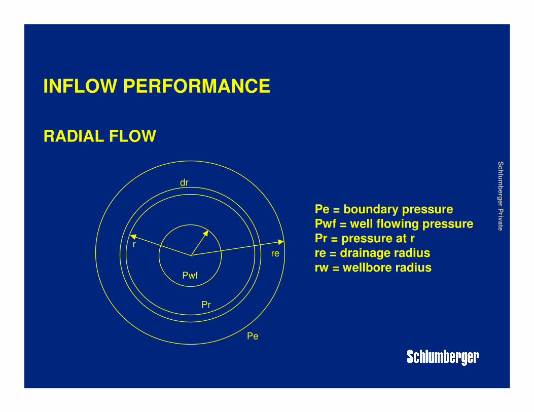
INFLOW PERFORMANCE
RADIAL FLOW
Pwf
Pe
dr
rre
Pr
Pe = boundary pressurePwf = well flowing pressure
Pr = pressure at r
re = drainage radius
rw = wellbore radius

Sch
lum
berg
er P
rivate
Sch
lum
berg
er P
rivate
INFLOW PERFORMANCE
SEMI (PSEUDO) STEADY STATE INFLOW (using average reservoir pressure)
kh(Pav - Pwf)qo = -----------------------------------
141.2 µµµµ oBo.[ln(re/rw) - 3/4]
where:P = pressure (psi)k = permeability (md)
h = height (ft)
re = drainage radius (ft)
rw = wellbore radius (ft)
µµµµO = fluid viscosity (cP)Bo = formation volume factor (bbls/stb)
Sch
lum
berg
er P
rivate
Sch
lum
berg
er P
rivate
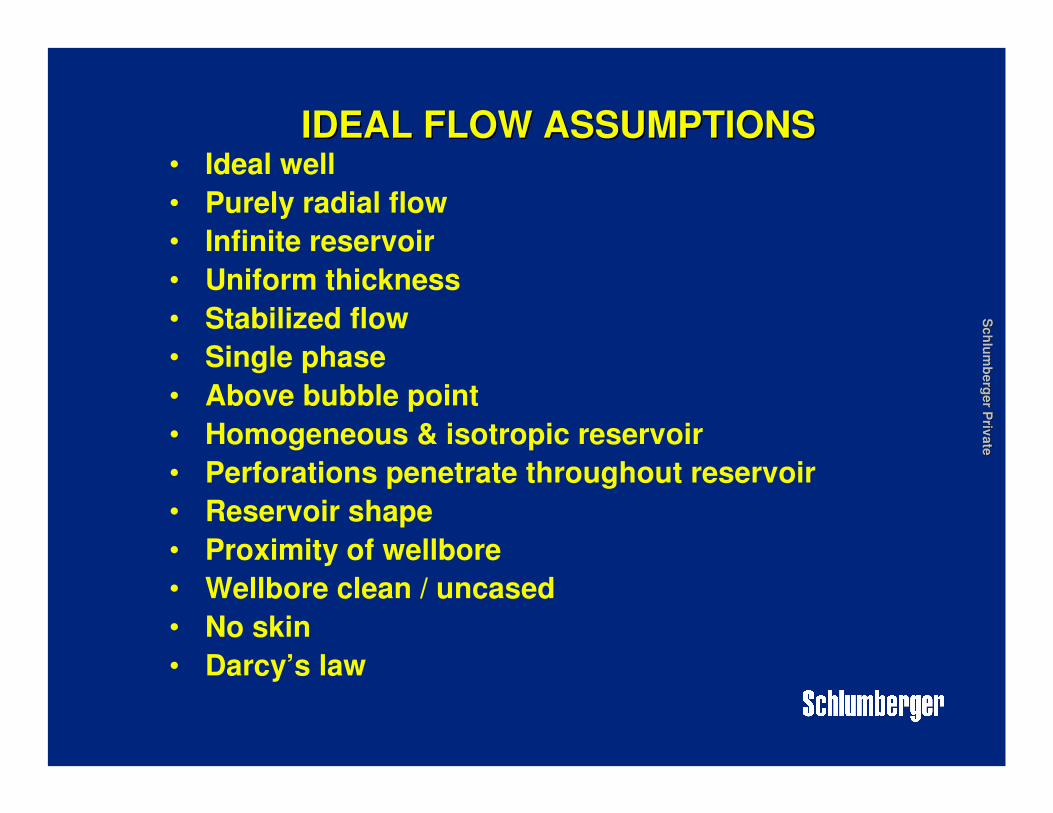
IDEAL FLOW ASSUMPTIONSIDEAL FLOW ASSUMPTIONS• Ideal well
• Purely radial flow
• Infinite reservoir
• Uniform thickness
• Stabilized flow
• Single phase
• Above bubble point
• Homogeneous & isotropic reservoir
• Perforations penetrate throughout reservoir
• Reservoir shape
• Proximity of wellbore
• Wellbore clean / uncased
• No skin
• Darcy’s law

Sch
lum
berg
er P
rivate
Sch
lum
berg
er P
rivate
NON IDEAL FLOW
• Departures from Darcy’s law
• Effects at boundaries
• Position of well
• Non homogeneous reservoir
• Perforation positions
• High velocities
• Fluid type / high GOR
• Transient behavior
• Relative permeability effects - oil/water/gas near the wellbore
• Depletion if reservoir
• Flow restrictions (skin)

Sch
lum
berg
er P
rivate
Sch
lum
berg
er P
rivate
INFLOW PERFORMANCE
SKIN
• Ideal flow conditions rarely exist
• Restricted flow into the wellbore
• The total skin factor may be calculated from well test
data

Sch
lum
berg
er P
rivate
Sch
lum
berg
er P
rivate
INFLOW PERFORMANCE
PRINCIPLE ORIGINS OF SKIN
• Formation damage (+ve)
• Perforations (+ve)
• Partial completions/limited entry (+ve)• Gravel packs (+ve)
• Non-Darcy flow (+ve)• Multiphase flow (+ve)
• Natural fractures (-ve)
• Hydraulic fractures (-ve)• Deviated/horizontal wells (-ve)

Sch
lum
berg
er P
rivate
Sch
lum
berg
er P
rivate
INFLOW PERFORMANCE
PRODUCTIVITY INDEX
The relationship between well inflow rate and pressuredrawdown can be expressed in the form of a Productivity Index, denoted ‘PI’ or ‘J’, where:
qq = J(Pws - Pwf) or J = ------------------
Pws - Pwf
kh(Pav - Pwf)
qo = -----------------------------------
141.2 µµµµ oBo.[ln(re/rw) - 3/4]

Sch
lum
berg
er P
rivate
Sch
lum
berg
er P
rivate
WELL & RESERVOIR INFLOW PERFORMANCE( Successful design depends upon prediction of flow rate)
FACTORS AFFECTING PI
1. Phase behaviour•Bubble point pressure•Dew point pressure
2. Relative permeability behaviour•Ratio of effective permeability to a particular fluid (oil, gas or water) to the absolute permeability of the rock
3. Oil viscosity•Viscosity decreases with pressure decrease to Pb•Viscosity increases as gas comes out of solution
4. Oil formation volume factor (bo)
•As pressure is decreased the liquid will expand•As gas comes out of solution oil will shrink
Sch
lum
berg
er P
rivate
Sch
lum
berg
er P
rivate
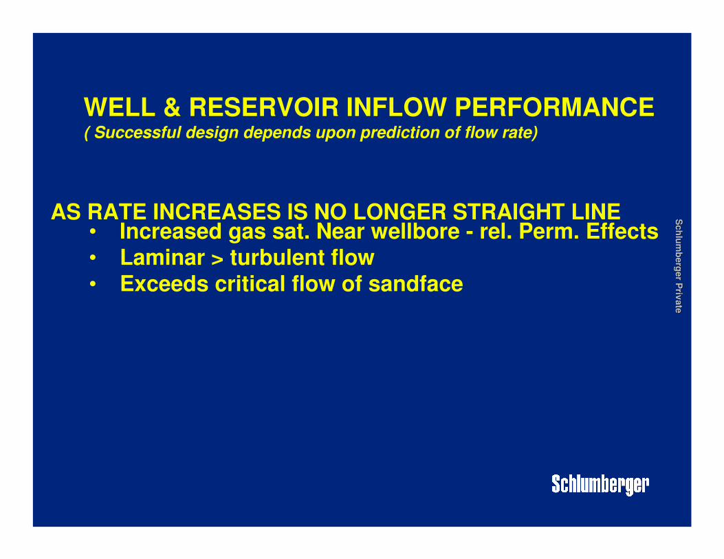
AS RATE INCREASES IS NO LONGER STRAIGHT LINE• Increased gas sat. Near wellbore - rel. Perm. Effects• Laminar > turbulent flow• Exceeds critical flow of sandface
WELL & RESERVOIR INFLOW PERFORMANCE( Successful design depends upon prediction of flow rate)
Sch
lum
berg
er P
rivate
Sch
lum
berg
er P
rivate
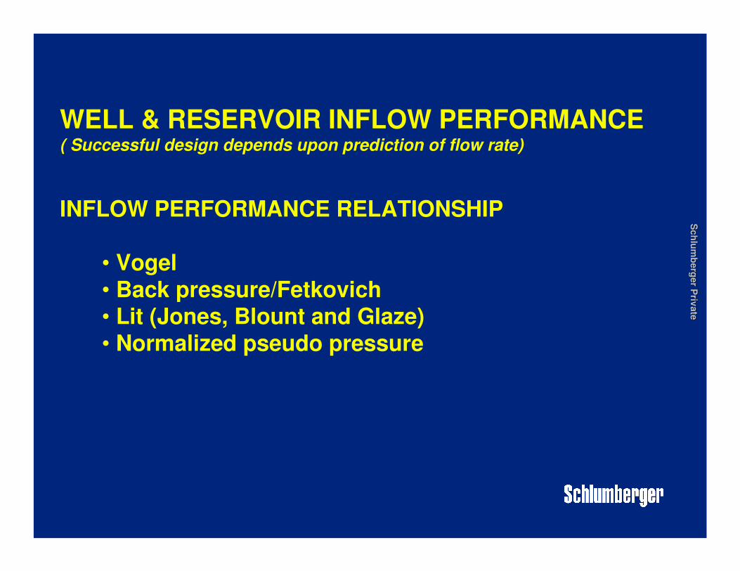
WELL & RESERVOIR INFLOW PERFORMANCE( Successful design depends upon prediction of flow rate)
INFLOW PERFORMANCE RELATIONSHIP
• Vogel• Back pressure/Fetkovich• Lit (Jones, Blount and Glaze)• Normalized pseudo pressure

Sch
lum
berg
er P
rivate
Sch
lum
berg
er P
rivate
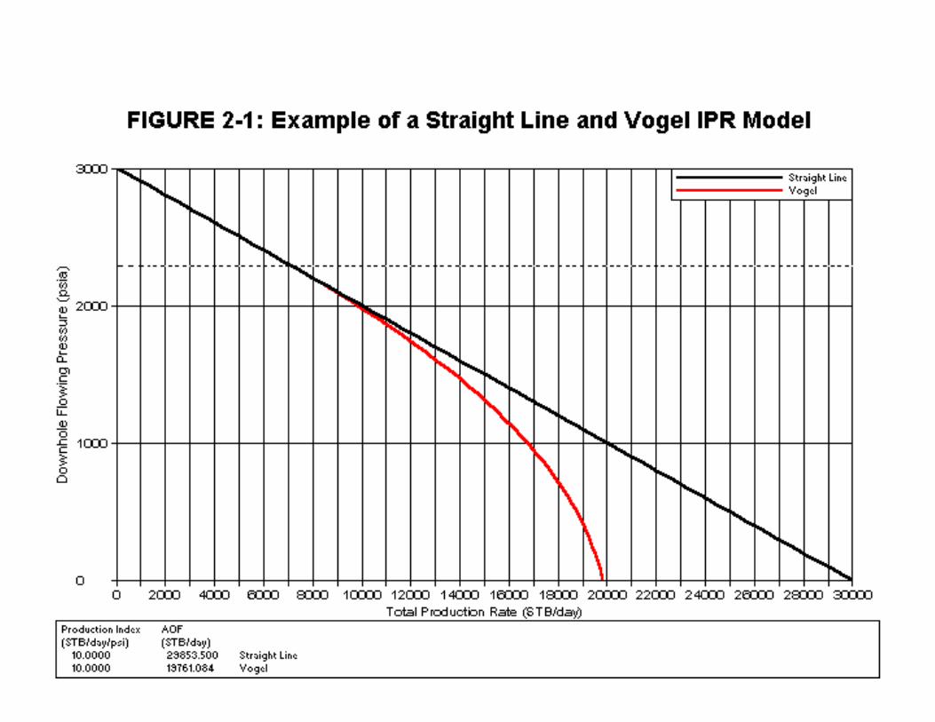
WELL & RESERVOIR INFLOW PERFORMANCE( Successful design depends upon prediction of flow rate)
VOGEL
Dimensionless reference curve based on the following equation:
Q/Qmax = 1 - 0.2(Pwf/Pws) - 0.8(Pwf/Pws)2
where: Q = the liquid production rate, stb/dQmax = the maximum liquid rate for 100% drawdownPwf = bottom hole flowing pressure, psiPws = the reservoir pressure, psi
Sch
lum
berg
er P
rivate
Sch
lum
berg
er P
rivate
Sch
lum
berg
er P
rivate
Sch
lum
berg
er P
rivate
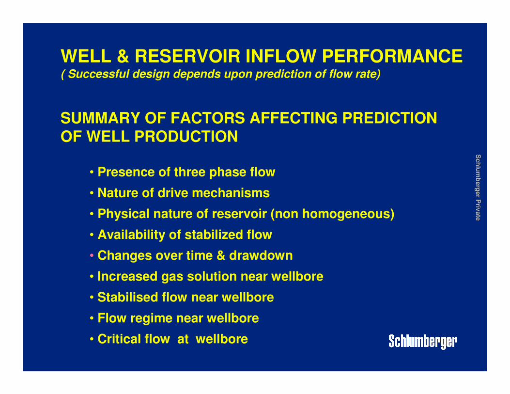
WELL & RESERVOIR INFLOW PERFORMANCE( Successful design depends upon prediction of flow rate)
SUMMARY OF FACTORS AFFECTING PREDICTIONOF WELL PRODUCTION
• Presence of three phase flow
• Nature of drive mechanisms
• Physical nature of reservoir (non homogeneous)
• Availability of stabilized flow
• Changes over time & drawdown
• Increased gas solution near wellbore
• Stabilised flow near wellbore
• Flow regime near wellbore
• Critical flow at wellbore
Sch
lum
berg
er P
rivate
Sch
lum
berg
er P
rivate
MULTIPHASE FLOWOUTFLOW PERFORMANCE
MOVEMENT OF A MIXTURE OF FREE GASES AND LIQUIDS
Vertical flowing gradients
Horizontal flowing gradients

Sch
lum
berg
er P
rivate
Sch
lum
berg
er P
rivate
FACTORS EFFECTING VLP
� VLP is a function of physical properties not inflow• Tubing ID
• Wall roughness• Inclination• Liquid / gas density• Liquid / gas viscosity• Liquid / gas velocity• Well depth / line lengths• Surface pressure• Water cut• GOR• Liquid surface tension• Flowrate

Sch
lum
berg
er P
rivate
Sch
lum
berg
er P
rivate
PRESSURE LOSS IN WELLBORE
‘Complicated expression’

Sch
lum
berg
er P
rivate
Sch
lum
berg
er P
rivate
• System described by a energy balance expression• Mass energy per unit mass in = energy out • (+ - exchange with surroundings)• For wellbore- pressure Calc. for length of pipe• Integrated each section• Pressure can be divided into three terms
ZZ
δδδδP/δδδδZ
Sch
lum
berg
er P
rivate
Sch
lum
berg
er P
rivate
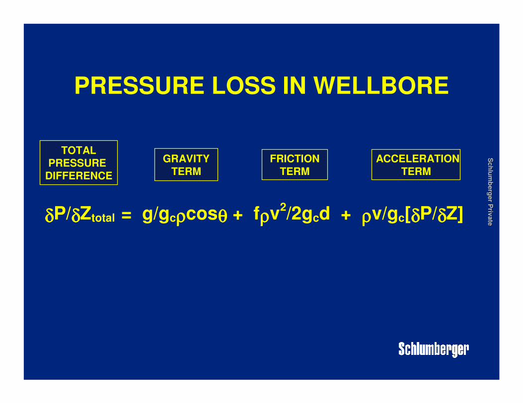
PRESSURE LOSS IN WELLBORE
δδδδP/δδδδZtotal = g/gcρρρρcosθθθθ + fρρρρv2/2gcd + ρρρρv/gc[δδδδP/δδδδZ]
TOTAL
PRESSURE
DIFFERENCE
GRAVITY
TERM
ACCELERATION
TERM
FRICTION
TERM
Sch
lum
berg
er P
rivate
Sch
lum
berg
er P
rivate
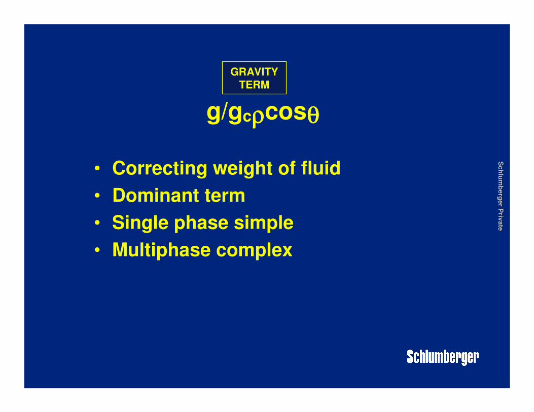
• Correcting weight of fluid
• Dominant term
• Single phase simple
• Multiphase complex
g/gcρρρρcosθθθθ
GRAVITY
TERM
Sch
lum
berg
er P
rivate
Sch
lum
berg
er P
rivate
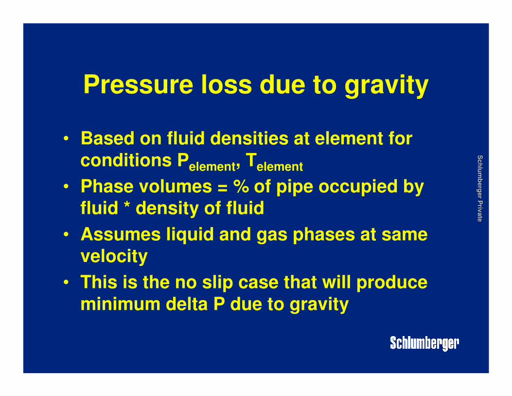
Pressure loss due to gravity
• Based on fluid densities at element for
conditions Pelement, Telement
• Phase volumes = % of pipe occupied by
fluid * density of fluid
• Assumes liquid and gas phases at same
velocity
• This is the no slip case that will produce
minimum delta P due to gravity
Sch
lum
berg
er P
rivate
Sch
lum
berg
er P
rivate
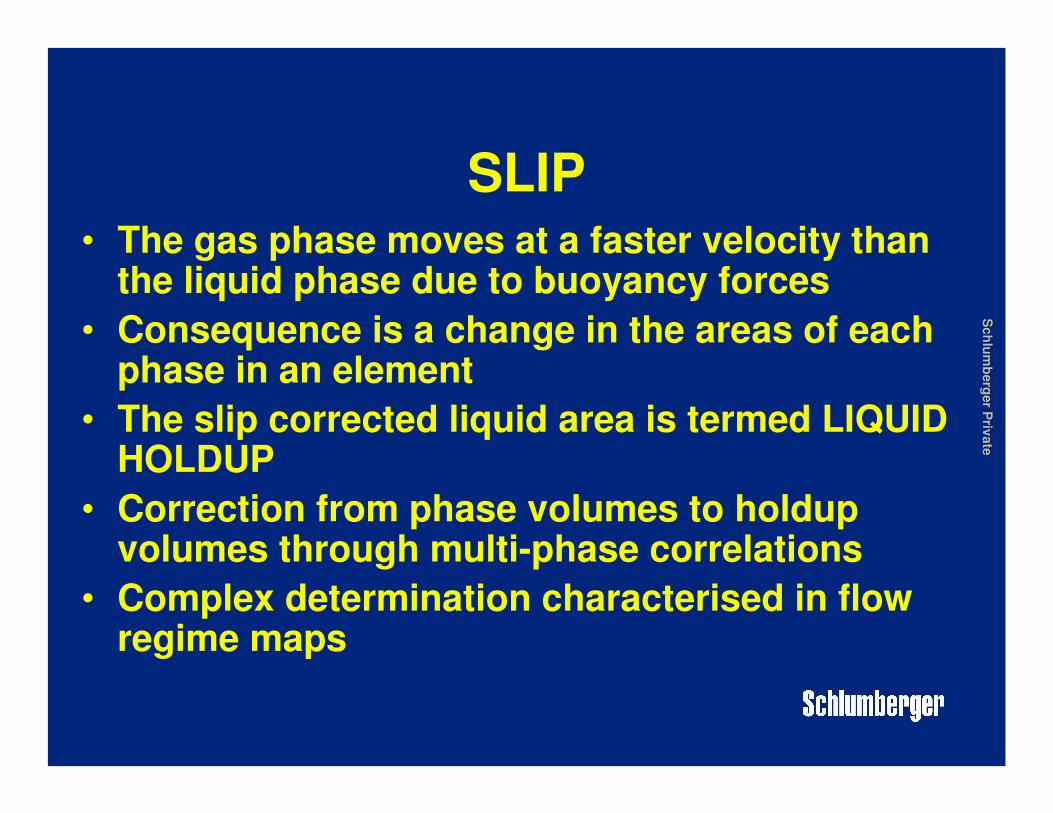
SLIP• The gas phase moves at a faster velocity than
the liquid phase due to buoyancy forces
• Consequence is a change in the areas of each phase in an element
• The slip corrected liquid area is termed LIQUID HOLDUP
• Correction from phase volumes to holdup volumes through multi-phase correlations
• Complex determination characterised in flow regime maps

Sch
lum
berg
er P
rivate
Sch
lum
berg
er P
rivate
Liquid Holdup
• Consider an element for Pelement , Telement
LIQUIDLIQUID GASGAS
LIQUIDLIQUID GASGAS
% Liquid% Liquid % Gas % Gas
Liquid Liquid HoldupHoldup 1 1 -- Liquid Liquid HoldupHoldup
Slip correctedSlip corrected
Mixture density = L Mixture density = L densitydensity * % L + G * % L + G densitydensity * %G* %G
Mixture density = L Mixture density = L densitydensity * H* HLL + G + G densitydensity * (1* (1--HHLL))
Sch
lum
berg
er P
rivate
Sch
lum
berg
er P
rivate
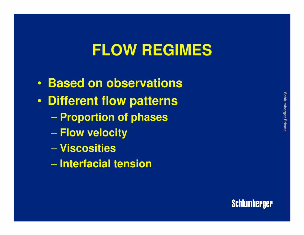
FLOW REGIMES
• Based on observations
• Different flow patterns
– Proportion of phases
– Flow velocity
– Viscosities
– Interfacial tension

Sch
lum
berg
er P
rivate
Sch
lum
berg
er P
rivate
FLOW REGIMESFLOW REGIMES
Sch
lum
berg
er P
rivate
Sch
lum
berg
er P
rivate
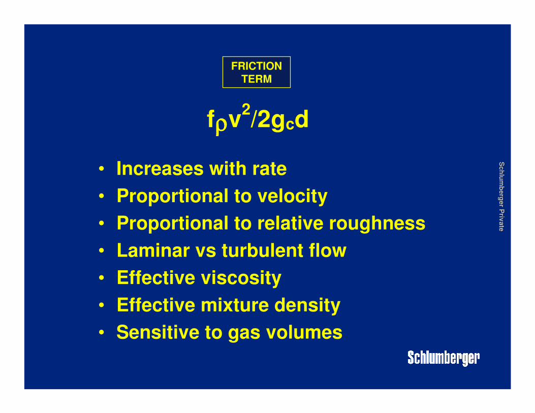
• Increases with rate
• Proportional to velocity
• Proportional to relative roughness
• Laminar vs turbulent flow
• Effective viscosity
• Effective mixture density
• Sensitive to gas volumes
fρρρρv2/2gcd
FRICTION
TERM
Sch
lum
berg
er P
rivate
Sch
lum
berg
er P
rivate
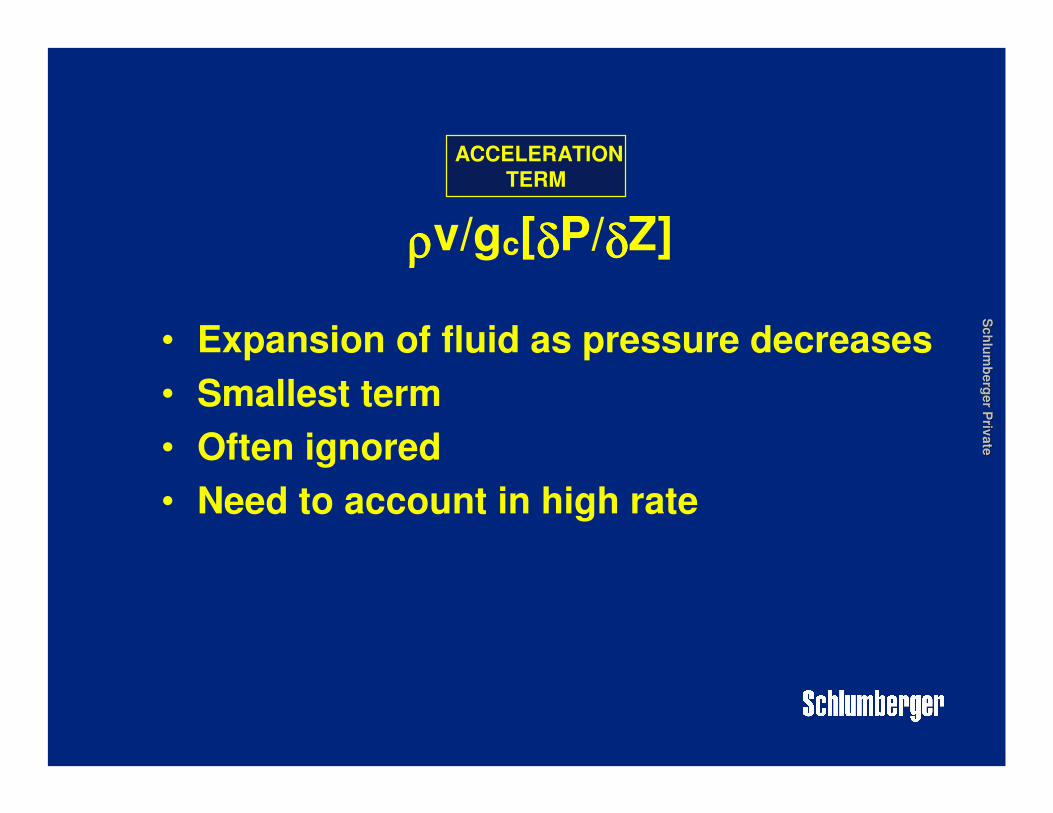
• Expansion of fluid as pressure decreases
• Smallest term
• Often ignored
• Need to account in high rate
ρρρρv/gc[δδδδP/δδδδZ]
ACCELERATION
TERM

Sch
lum
berg
er P
rivate
Sch
lum
berg
er P
rivate
Proportion of terms in oil well close to
sandface (no significant GLR)
GRAVITY
FRICTION
ACCELERATION
Proportion of terms in oil well significant
GLR close to surface
GRAVITY
FRICTION
ACCELERATION

Sch
lum
berg
er P
rivate
Sch
lum
berg
er P
rivate
• Fluid density in every term• Errors would be cumulative• PVT important
PRESSURE LOSS IN WELLBORE

Sch
lum
berg
er P
rivate
Sch
lum
berg
er P
rivate
CORRELATIONS• Babson (1934)
• Gilbert (1939 / 1952)
• Poettmann & Carpenter (1952)
• Duns & Ros
• Hagedorn & Brown
• Orkiszewski
• Fancher & Brown
• Beggs &Brill
• Duckler Flannigan
• Gray
• Mechanistic
• Proprietary

Sch
lum
berg
er P
rivate
Sch
lum
berg
er P
rivate
0
1000
2000
3000
4000
5000
6000
7000
8000
9000
10000
11000
12000
13000
14000
0 1000 2000 3000 4000 5000
Pressure, psig
Dep
th,
fee
t
4200
4400
4600
4800
5000
5200
0 1000 2000 3000
Rate, bbls/d
FB
HP
, p
sig
INFLOW AND OUTFLOW
PERFORMANCE

Sch
lum
berg
er P
rivate
Sch
lum
berg
er P
rivate
Effect of Skin on IPR
Outflow
Flowrate
Pre
ssu
re a
t N
od
e
5 0 -1 -3
SKIN
Inflow(IPR)
qo
αααα 1/ ln re +S
rw
Note : Log effect
10

Sch
lum
berg
er P
rivate
Sch
lum
berg
er P
rivate
Effect of Pressure Depletion on IPR
Outflow
Flowrate
Pre
ssu
re a
t N
od
eReservoir with no pressure support
Inflow
Decreasing reservoir pressureDecreasing reservoir pressure

Sch
lum
berg
er P
rivate
Sch
lum
berg
er P
rivate
Effect of Tubing Size on Outflow
Inflow(IPR)
Outflow
Flowrate (stb/d)
Pre
ssu
re a
t N
od
e
2 3/8”
2 7/8”4 1/2”
3 1/2”

Sch
lum
berg
er P
rivate
Sch
lum
berg
er P
rivate
Pressure versus Depth for
various Artificial Lift Methods

Sch
lum
berg
er P
rivate
Sch
lum
berg
er P
rivate
Natural Flow Pressure vs Depth
Sch
lum
berg
er P
rivate
Sch
lum
berg
er P
rivate
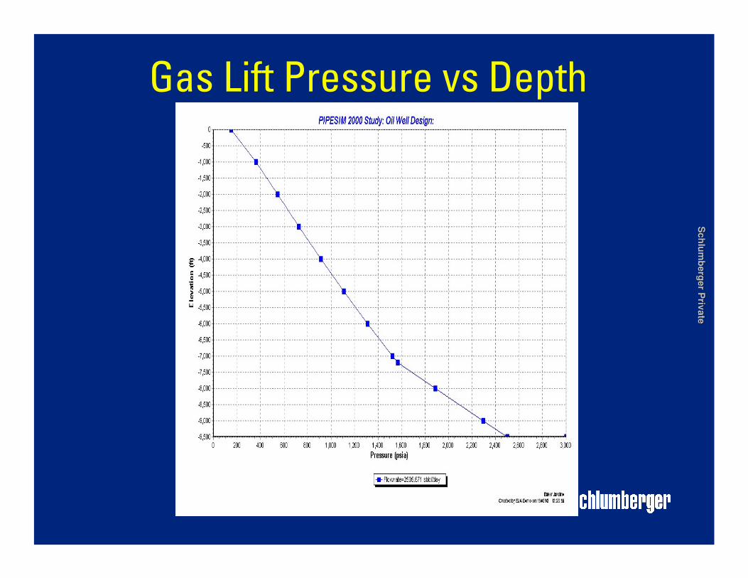
Gas Lift Pressure vs Depth
Sch
lum
berg
er P
rivate
Sch
lum
berg
er P
rivate
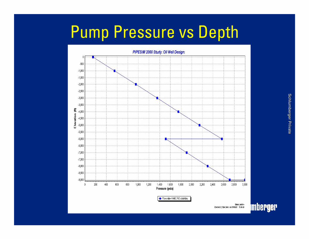
Pump Pressure vs Depth


