14
1 IRS2980 Buck LED Driver Peter Green Under embargo until 10/25/11
| Date post: | 16-Dec-2015 |
| Category: |
Documents |
| Upload: | edward-joseph |
| View: | 216 times |
| Download: | 1 times |

1
IRS2980Buck LED DriverPeter GreenUnder embargo until 10/25/11

Target Applications and Markets
• Non-isolated LED drivers where input voltage > output voltage• LED light bulb replacements (non-dimmable)
• LED tube replacements
• LED street lighting
• LED office light fixtures
• LED refrigerator lighting
• LED runway lighting
• Solar LED street light
• Gaming machines

Existing Solutions
• Passive LED driver circuits
• Use diodes, resistors and capacitors only
• LED current is limited (many small LEDs)
• Cheap but poor performance and reliability
• Low-voltage Buck LED drivers
• Peak current regulated Buck LED drivers
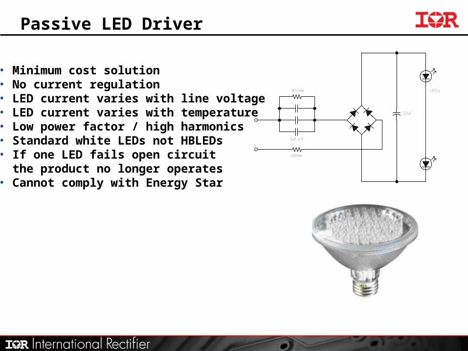
Passive LED Driver
1uF x 3
15Ohm
LEDs1MOhm
22uF
• Minimum cost solution• No current regulation• LED current varies with line voltage• LED current varies with temperature• Low power factor / high harmonics• Standard white LEDs not HBLEDs• If one LED fails open circuit the product no longer operates• Cannot comply with Energy Star
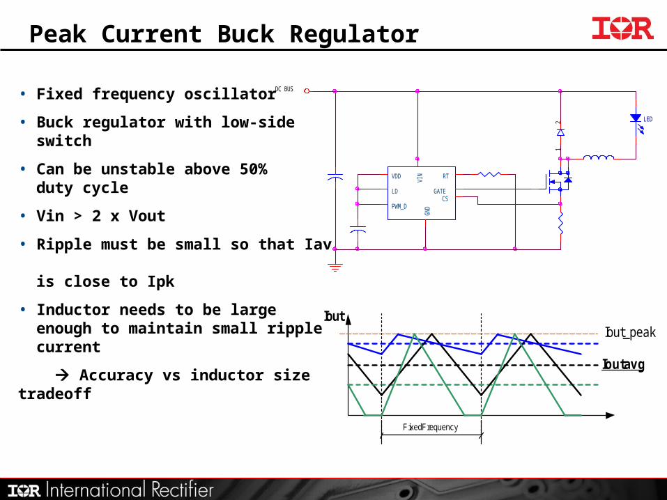
Peak Current Buck Regulator
• Fixed frequency oscillator
• Buck regulator with low-side switch
• Can be unstable above 50% duty cycle
• Vin > 2 x Vout
• Ripple must be small so that Iav is close to Ipk
• Inductor needs to be large enough to maintain small ripple current
Accuracy vs inductor size tradeoffIout avg
Fixed Frequency
Iout_peakIout
LED
VDD
LD
PWM_D
VIN RT
GATECS
GND
12
DC BUS

IR Solution
IRS2980:• Available in SO8 package
• High-voltage Buck continuous mode LED driver (up to 375V continuous)
• Floating differential current sense
• Accurate constant current control (average current control)
• Internal HV regulator (no separate VCC supply needed)
• On board PWM dimming oscillator (not triac dimmable without additional circuitry)
• Frequency limiter (150kHz prevents internal regulator overheating and limits switching losses in the MOSFET and diode)
• May be used with passive valley fill PFC to obtain PF > 0.7
Trademark and logo for IR new LED driver family:

IRS2980 LED Driver
VBUS
COM
1
2
3
4
8
7
6
5
IRS
2980
HV
VS
COM ADIM
RAMP
OUT
CS
VCC
ADIM
RCS
RG
LBUCK
MBUCK
CRAMP
CVCC
CBUS
DBUCK
CVF
• Free running frequency• Buck regulator with low-side switch• High-side current sensing• Average current hysteretic control• Stable over full operating range• Higher ripple can be tolerated without• excessive loss in accuracy• PWM Dimming with analog control• Inductor needs to be large enough to• limit ripple current• Accuracy vs inductor size tradeoff
IRS2980
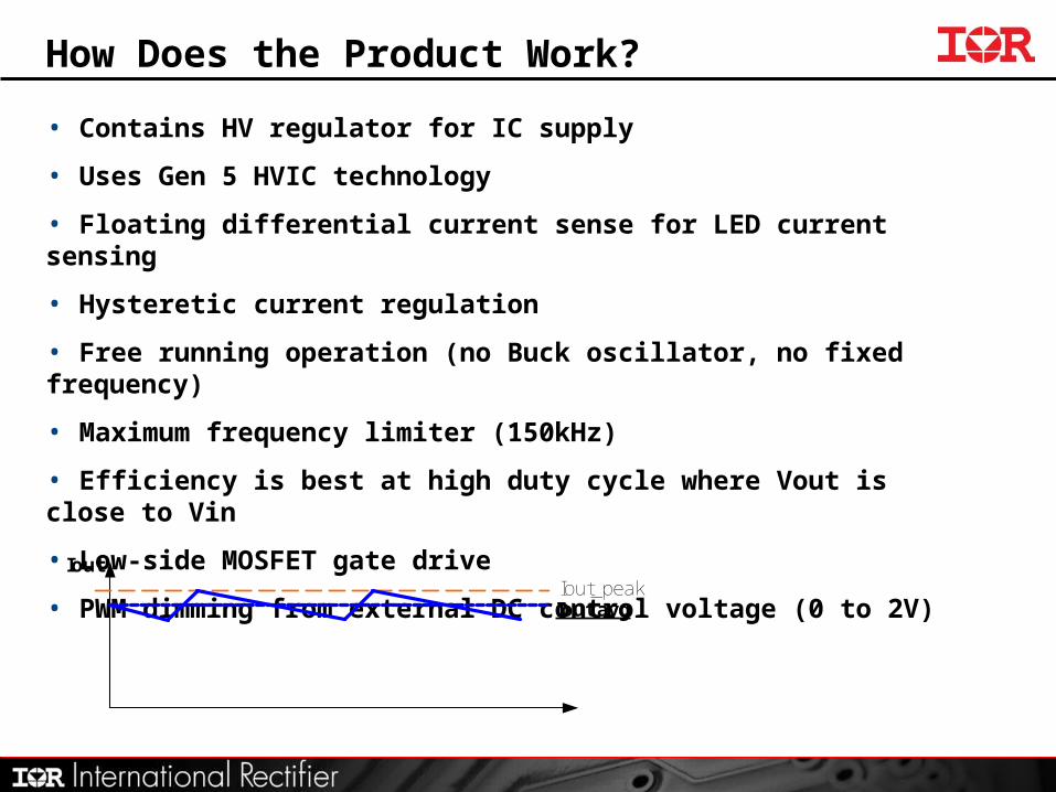
How Does the Product Work?
• Contains HV regulator for IC supply
• Uses Gen 5 HVIC technology
• Floating differential current sense for LED current sensing
• Hysteretic current regulation
• Free running operation (no Buck oscillator, no fixed frequency)
• Maximum frequency limiter (150kHz)
• Efficiency is best at high duty cycle where Vout is close to Vin
• Low-side MOSFET gate drive
• PWM dimming from external DC control voltage (0 to 2V)
Iout avgIout_peak
Iout

Low Cost IRS2980 LED Driver
• Low cost passive “Valley fill” PFC can be used in off line Buck regulators.• Provides power factor ~0.9.• It is constrained by ripple on DC bus being regulated out to provide a constant output current.
1
2
3
4
8
7
6
5IR
S2980
HV
VS
COM ADIM
RAMP
OUT
CS
VCC
RCS
RG
LBUCK
MBUCK
CRAMP
CVCC
CBUS1
DBUCK
CVF
LIN
CIN
DB1 DB2
DB3 DB4
CFRF
CBUS2
D1
D2
D3
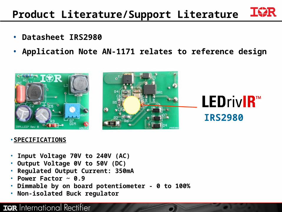
Product Literature/Support Literature
• Datasheet IRS2980
• Application Note AN-1171 relates to reference design IRPLLED7
IRS2980
•SPECIFICATIONS
• Input Voltage 70V to 240V (AC)• Output Voltage 0V to 50V (DC)• Regulated Output Current: 350mA• Power Factor ~ 0.9• Dimmable by on board potentiometer - 0 to 100%• Non-isolated Buck regulator

Typical Results (IRPLLED7 Demo Board)
Input = 60VDC Input = 180VDCOutput = 20V / 350mA Output = 20V / 350mAEfficiency = 80.2% Efficiency = 75.3%Green Trace = Gate DriveBlue Trace = Output Current

PWM Dimming Option
1
2
3
4
8
7
6
5
IRS
2980
HV
VS
COM ADIM
RAMP
OUT
CS
VCC
RCS
RG
LBUCK
MBUCK
CRAMP
CVCC
CBUS
DBUCK
CVF
LIN
CIN
DB1 DB2
DB3 DB4
CFRF
RDIM
RVDIM
• 0 to 2VDC analog control on ADIM input
• Adjusts PWM duty cycle for dimming (0 to 100%)
• CRAMP determines the PWM frequency
• PWM direct input is possible through ADIM
(replace CRAMP with resistor to set threshold)

PWM Dimming
Analog or Digital dimming signal is applied to the DIM input
ADIM voltage relationship to light output
0
10
20
30
40
50
60
70
80
90
100
0 0.2 0.4 0.6 0.8 1.0 1.2 1.4 1.6 1.8 2.0Du
ty C
ycle
(%
)
Per
cen
tag
e o
f L
igh
t O
utp
ut
ADIM pin voltage

IRS2980 IC Summary
• For LED driver applications (typically < 50W)• For off line AC input voltage range 90 to 265VAC• Internal High Voltage Regulator• Power Factor > 0.9 with passive valley fill input stage• Continuous Conduction Mode (CCM) Buck Regulator• Typical Efficiency >80% (depending on line and load)• Suitable for non-isolated LED drivers• Protected against output short circuit• Regulated output current for LED driving• Hysteretic Average Current Control (for accurate regulation)• PWM dimming input, controlled by analog or PWM input


![Bridgeless Buck-Boost PFC Converter for Multistring LED Driver€¦ · boost converter as a universal PFC converter [6]. In order to address these issues, a buck-boost converter is](https://static.documents.pub/doc/80x56/5eaabf2a4ab79d1e774f9005/bridgeless-buck-boost-pfc-converter-for-multistring-led-driver-boost-converter-as.jpg)


