1 LARP Magnet Program G. Ambrosio Many slides from (with a few modifications): Jim Kerby for the LARP Magnet Collaboration 25 October 2006 Rad-Hard Insulation Workshop Fermilab – Apr 20, 2007
Transcript
1
LARP Magnet ProgramG. Ambrosio
Many slides from (with a few modifications): Jim Kerby for the LARP Magnet Collaboration
Mission Statement:The US LHC Accelerator Research Program enables U.S. accelerator specialists to take an active and important role in the LHC accelerator during its commissioning and operations, and to be a major collaborator in LHC performance upgrades. In particular, LARP will support U.S. institutions in LHC commissioning activities and accelerator science, accelerator instrumentation and diagnostics, and superconducting magnet R&D to help bring the LHC on and up to luminosity quickly, to help establish robust operation, and to improve and upgrade LHC performance. Furthermore, the work we do will be at the technological frontier and will thereby improve the capabilities of the U.S. accelerator community in accelerator science and technology to more effectively operate our domestic accelerators and to position the U.S. to be able to lead in the development of the next generation of high-energy colliders.
3
US LHC Accelerator Research Program Magnet Systems
Provide options for future upgrades of the LHC Interaction Regions
Primary Focus: Demonstrate by 2009 that Nb3Sn magnets are a viable choice for an LHC IR upgrade
– The major issues: Nb3Sn technology, consistency, bore/gradient (field), length
– Three phase approach
1. Predictable and reproducible performance
TQ models (1 m, 90 mm aperture, Gnom > 200 T/m, Bcoil > 12 T)
2. Long magnet fabrication
LQ models (4 m, 90 mm aperture, Gnom > 200 T/m, Bcoil > 12 T)
3. High gradient in large aperture
HQ models (1 m, 90+ mm aperture, Gnom > 250 T/m, Bcoil > 15 T)
4
Technological Quadrupoles
Two mechanical designs are under development
Same coils / Aperture = 90 mm / Gradient > 200 T/m @ 4.2K
2 layers
FillerKeys
4 pads
Bladder
Yoke
Aluminum shell
YokeGap
PreloadShim
ControlSpacer
Skin
Collar
YokeCollaringKey
Stress Relief Slotin inner pole
TQC: using collarsCollar laminations from LHC-IR quads1st time applied to Nb3Sn coils
TQS: using Al-shellPre-loaded by bladders and keys1st time applied to shell-type coils
Winding & curing (FNAL - all coils) Reaction & potting (LBNL - all coils)
6
“Baseline Strand”
• Rod Re-Stack Process, RRP 54/61 Design
– 0.7mm diameter
– Filament diameter ~ 70 m
– Jc in the range of 2400-3000 A/mm2 at 12T
– RRR of stabilizer Cu > 100
– low field stability current Is
~ 1000 A and higher depending on reaction time/temperature
126/
127
126/
127
OST-RRP 54/61 design
-600
-400
-200
0
200
400
600
-4 -3 -2 -1 0 1 2 3 4 5 6
APPLIED FIELD [T]
MA
GN
ET
IZA
TIO
N [
kA
/m]
70 m
7
Conductor (2)
54/61 RRP conductor is in house
60/61 RRP under evaluation
- larger filament spacing, same Cu/non_Cu ratio (Cu = 47%)
108/127 or 120/127
- More thinner subelements more stable (flux jumps)1.
60/61 restack with spaced SE’s
8
S-Glass Sleeve application on Cable
S-Glass sizing removal
S-Glass is baked @ 875 F
Teflon Tube
S-Glass Sleeve
S-Glass: Palmitic Acid application
Insulation Procedure
9
Winding & Curing
After winding a ceramic binder is applied (painted) on the coil,the binder is cured at 150 C for 30 minutes (becoming a strong bonding agent),Coils are ready for heat treatment (~650 C in argon)
10
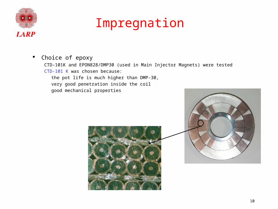
Impregnation
Choice of epoxyCTD-101K and EPON828/DMP30 (used in Main Injector Magnets) were tested
CTD-101 K was chosen because:
the pot life is much higher than DMP-30,
very good penetration inside the coil
good mechanical properties
11
Goal
By the end of 2009 LARP should deliver a successful Long Nb3Sn Quadrupole
It will be a Proof of Principle that Nb3Sn is a viable option for the LHC luminosity upgrade
In order to have a complete Proof of Principle we will have to address this question:
“Can this magnet withstand the expected radiation dose?”
We should be able to reply either:
“Yes it can, and we have data to demonstrate it”
“No it cannot, but we have tested a TQ with an insulation/impregnation scheme that can withstand the expected dose”
Plan A
Plan B
12
Plan A
Identify the most critical parameters of TQ-like magnets that can deteriorate under high radiation dose
– Depending on material and magnet design– Share/tension, swelling, thermal conductivity …
Plan tests of these properties before and after high dose irradiation (a few different doses)
Challenges: – Energy spectrum and dose: reactors, beams (size?), LHC?– Need hot cell?– Need to keep samples cold?
13
Plan A possible results
OK, the present insulation/impregnation
scheme can withstand the expected dose We can optimize the
absorbers so that it can withstand the expected
dose
No way,We need a plan B!
14
Plan B
Goal: select a material for coil impregnation that can withstand the expected max dose and is compatible with LARP Nb3Sn coil fabrication technology
– Possible candidates: cyanate ester, mixture with epoxy, matrimid, other polyimides…
– Evaluate compatibility with Nb3Sn coil fabrication technology
• Good impregnation, binder compatible, …
15
Time frame
Plan A Plan B
FY07 Develop plans, schedule, cost
Select alternative material
FY08
Q1-Q2
Prepare samples and fixtures
FY08
Q3-Q4
Irradiation & tests
Irradiation & tests
FY09 SQ and/or TQ
16
Rad-Hard Insulation Workshop AGENDA: 1:30 Introduction 20 G. Ambrosio LARP Magnets Mechanical Analysis 20 I. Novitzky Radiation Environment in the LARP IR Magnets
and Needs for Radiation Tests 30 N. Mokhov
Radiation Effects to Nb3Sn, Copper and Inorganic Materials
20 A. Zeller
3:30 Break 20 Current Knowledge of Radiation Tolerance of
Epoxies 20 R. Reed
Radiation-Resistant Insulation for High-Field Magnet Applications
30 M. Hooker
New Wind-and-React Insulation Application Process
10 M. Hooker
Discussion about test needs, samples, and available test facilities
All
Summary and plans All
17
Questions
Develop plan to arrive to these answers:
“Can this magnet withstand the expected radiation dose?”
We should be able to reply either:
- “Yes it can, and we have data to demonstrate it”
- “No it cannot, but we have tested a TQ with an insulation/impregnation scheme that can withstand the expected dose”
18
Appendix
19
939R
946R
Facet Size Determination
20
LR/LM/LQ: Long Magnet Fabrication
Long Racetrack (4m)
– Coil fabrication scale-up based on well-understood sub-scale coils
– Explore length scale-up of coils in shell-based support structure
– LR design complete– BNL practice winding, installation of necessary
tooling underway, oven shipped this week– Tech transfer to BNL w/ SRS01 test successful
Mirror dipole scale-up via FNAL core program
– 2m practice coils under reaction, winding of 2m coils underway 4 m coils to follow
Long quadrupole (LQ)
– 3.6 m quadrupole based on TQ cross-section—initial coils and tooling designs in study
21
Beyond TQ: High Gradient Quadrupoles
TABLE II PERFORMANCE PARAMETERS
Parameter Symbol Unit HQ1 HQ2 Short sample gradient* Gss T/m 308 317 Short sample current* Iss kA 10.7 12.6 Coil peak field Bpk (Iss) T 15.6 15.8 Copper current density Jcu (Iss) kA/mm2 2.2/2.2 2.1/2.6 Inductance L (Iss) mH/m 24.5 18.0 Stored energy U (Iss) MJ/m 1.3 1.4 Lorentz force/octant (r) Fr (Iss) MN/m 1.7 1.7 Lorentz force/octant () F (Iss) MN/m -6.0 -6.1 Average coil stress () (Iss) MPa 150 152 Dodecapole (22.5 mm) b6 -0.2 0.0 10-pole (22.5 mm) b10 -0.05 -0.92