24
1 Lecture 3: Introducing Data Flow Diagrams (DFDs) Section 1 - The Concept of Diagrams • Why use Diagrams? • Diagrams as Working Documents • Systems Analysis Modelling Techniques
| Date post: | 28-Dec-2015 |
| Category: |
Documents |
| Upload: | tyler-bryant |
| View: | 217 times |
| Download: | 0 times |

1
Lecture 3:Introducing Data Flow Diagrams (DFDs)Section 1 - The Concept of Diagrams
• Why use Diagrams?• Diagrams as Working Documents• Systems Analysis Modelling Techniques

2
Why Use Diagrams?
• To help overcome the communication problem between users and developers.
• Use of natural language, written or spoken open to– misinterpretation– ambiguities– omissions
• Diagrams– help communication– help understanding– are unambiguous

3
Why Use Diagrams (Cont’d)
DEVELOPERS (have discussions with users etc) CREATE DIAGRAMS (to record
understanding) AMEND DIAGRAMS (with further
information)
USE DIAGRAMS as the BASE OF SYSTEM STRUCTURE

4
Diagrams as Working Documents
• Diagrams are working documents:– changes will occur (for correctness)
– changes must be documented and tracked
• Change is integral to the development process.

5
Systems Analysis - Modelling Techniques (Examples)
• Data Flow Diagrams
• Entity Relationship Diagrams
• Normalisation
• Entity-Life Histories

6
Lecture 3:Introducing Data Flow Diagrams (DFDs)Section 2 - Data Flow Diagrams (DFDs)
• Data Flow Diagramming• DFD Notation• DFD Levelling• Guidelines for Drawing DFDs• Connectivity & Validation

7
Data Flow Diagramming
• Business users normally define their business operation in terms of the processes of that operation.
• The process view of a system may be modelled by a Data Flow Diagram (DFD).
A process may be defined as an action or series ofactions which produce a change or development.

8
Data Flow Diagramming (Cont’d)
• DFDs concentrate upon the data needed to support the information requirements of a system:– what data is needed
– the processes that convert it.
• Data flow diagrams provide:
– the notion of structure
– static pieces of documentation
– communication tool
• DFDs are one of the most powerful and useful techniques available to the systems analyst.

9
DFD Notation
A DFD has four key components.
External Entity
Process
Data Store
Data Flows

10
Processes
• Processes are the individual tasks which when completed in a certain sequence fulfil the overall goal of the system of which they are a part.
Sales Clerk
Validate Customer Order
2
Processes transform input into output.
11
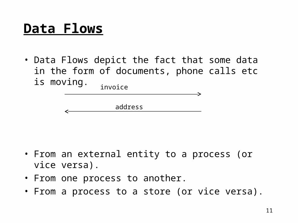
Data Flows
• Data Flows depict the fact that some data in the form of documents, phone calls etc is moving.
• From an external entity to a process (or vice versa).
• From one process to another.
• From a process to a store (or vice versa).
invoice
address

12
Data Flows (Cont’d)
Write data to a file
Take data from a file

13
Data Flows (cont’d)• Data flow names should be different if the form of their
data elements changes on entry to and exit from a process.
OrdersD1
Sales Clerk
Validate Order
1
Customer
StockD2
order
part_numbernew_order

14
Data Stores
• Data Stores contain data which is needed by a process in order for it to be completed.
• These show data ‘at rest’ within the system.
• They carry a description and are numbered D1, D2, D3 etc (computer data) or M1, M2, M3 etc (manual files).
D1 Stock

15
External Entity
• External entities exist in the system’s environment and either provide data to the system (sources) or receive data from the system (sinks).
• They are usually people, places, departments, organisations etc.
Customer

16
DFD Levelling
• DFDs allow the analyst to look at the system at different levels of detail.
• A business operation may contain many processes.
• The inclusion of all processes on a single diagram can:– make it look cluttered
– make it difficult to see exactly what a process does
• To overcome this it is usual to ‘break down’ the diagram, a process known as levelling.

17
DFD Levelling (See Lejk & Deeks p67)
ExternalEntity
ExternalEntity
Context Level 1 Level 2
OverallProcess
Process
Process
Process
1
2
3
2.1
2.2
2.3
Sub-process
Sub-process
Sub-process

18
Context Diagrams (Overview or Level 0)
• Represent the system at a high level of detail.
Comprised of:
• One single process box for the entire system.
• External entities.
• The data flows that pass between the external entities and the system.

19
Context Diagrams (cont’d)
Purpose:
• to identify and examine the interfaces between the external entities and the system.

20
Simple OrderSystem
Customer
Customer
order
delivery_detailsinvoice
Example Context Diagram

21
Level 1 Diagrams
Show:– the system in more detail
– how data enters the system
– how these data items are transformed by the processes
– how they leave the system
• A Level 1 diagram must have the same number of inputs and outputs as its context diagram.
• The flows are connected to and from the actual processes which create, receive or change them.
• Processes are numbered 1, 2, 3 etc on a Level 1 diagram.

22
Guidelines for Drawing a Context Diagram
• Read the case study a number of times.
• Try to list potential external entities.
• Establish what flows are sent to the system from the external entities.
• Establish what flows are sent from the system to the external entities.
• Draw the Context diagram.

23
Guidelines for Drawing a Level 1 Diagram
• Taking one sentence at a time try to identify potential processes (look for verbs).
• Identify and list the data flows.
• Identify and list the data stores.
• Draw the Level one diagram (using the correct notation).

24
‘Connectivity & Validation’
• Make sure the Level 1 diagram is fully connected.
• That is, a process must receive inputs from other processes or from data stores to be triggered.
• Check the Level 1 diagram against the context diagram for consistency:– flows across the boundaries must be the same
– names must be the same


