36
1 Machining Operations Part 1: Chapters 21, 22 Manufacturing Processes, 1311 Dr Simin Nasseri Southern Polytechnic State University
| Date post: | 17-Dec-2015 |
| Category: |
Documents |
| Upload: | brice-gallagher |
| View: | 230 times |
| Download: | 7 times |
1
Machining OperationsPart 1: Chapters 21, 22
Manufacturing Processes, 1311
Dr Simin Nasseri
Southern Polytechnic State University
Manufacturing ProcessesProf Simin Nasseri
Material Removal Processes
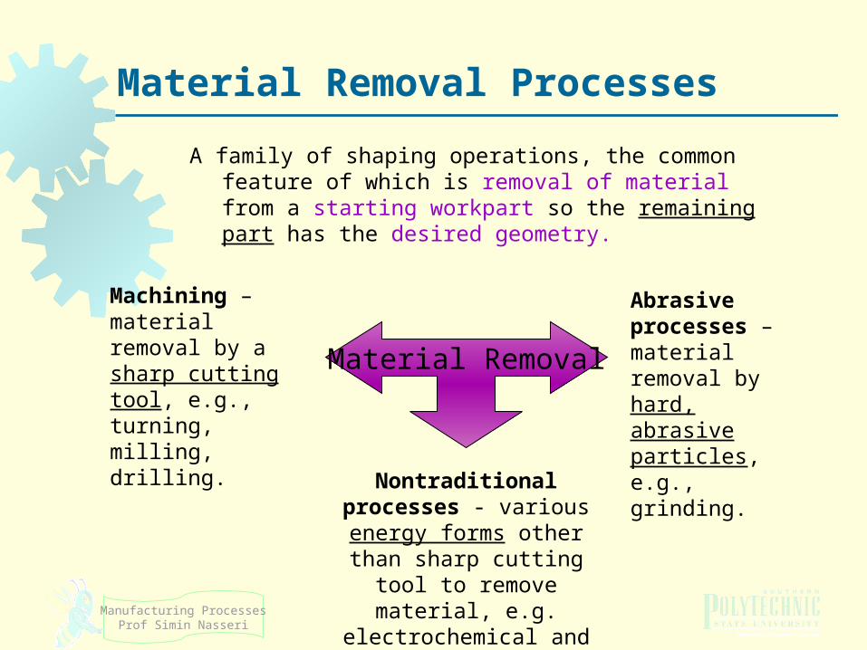
A family of shaping operations, the common feature of which is removal of material from a starting workpart so the remaining part has the desired geometry.
Material Removal
Machining – material removal by a sharp cutting tool, e.g., turning, milling, drilling.
Abrasive processes – material removal by hard, abrasive particles, e.g., grinding.
Nontraditional processes - various energy forms other than sharp
cutting tool to remove material, e.g. electrochemical and thermal energy
processes.
Manufacturing ProcessesProf Simin Nasseri
Reasons to MachineVariety of work materials can be machined.
Most frequently used to cut metals.Variety of part shapes and special geometric features possible,
Screw threads. Accurate round holes. Very straight edges and surfaces.
Improve dimensional accuracy of: Castings, forming, or shaping processes.
Produce features that cannot be produced by forming and shaping processes. External and internal profiles. Sharp corners. Flatness.
Remove distortion & discoloration from heat-treatment.Reduce manufacturing costs (usually small quantities).Apply special surface characteristics or textures.
Manufacturing ProcessesProf Simin Nasseri
Machining Limitations
Wasteful of material
Chips generated in machining are wasted material, at least in the unit operation
Time consuming
A machining operation generally takes more time to shape a given part than alternative shaping processes, such as casting, powder metallurgy, or forming
More expensive for mass production.
Consumes more energy.
Can have adverse effects on surface quality & properties.
Manufacturing ProcessesProf Simin Nasseri
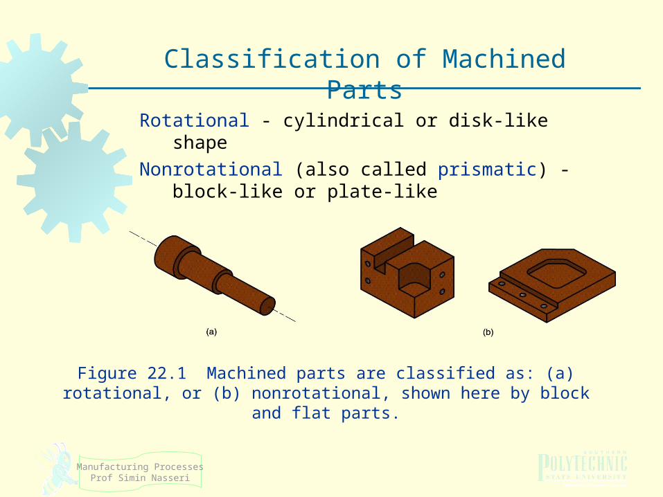
Rotational - cylindrical or disk‑like shape
Nonrotational (also called prismatic) - block‑like or plate‑like
Figure 22.1 Machined parts are classified as: (a) rotational, or (b) nonrotational, shown here by block and flat parts.
Classification of Machined Parts
Manufacturing ProcessesProf Simin Nasseri
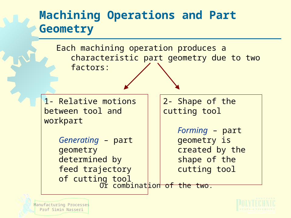
Machining Operations and Part Geometry
Each machining operation produces a characteristic part geometry due to two factors:
1- Relative motions between tool and workpart
Generating – part geometry determined by feed trajectory of cutting tool
2- Shape of the cutting tool
Forming – part geometry is created by the shape of the cutting tool
Or combination of the two.
Manufacturing ProcessesProf Simin Nasseri
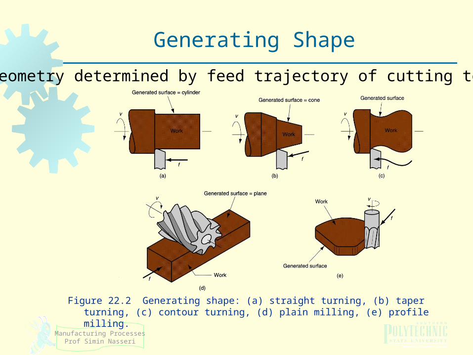
Figure 22.2 Generating shape: (a) straight turning, (b) taper turning, (c) contour turning, (d) plain milling, (e) profile milling.
Generating Shape
Part geometry determined by feed trajectory of cutting tool.
Manufacturing ProcessesProf Simin Nasseri
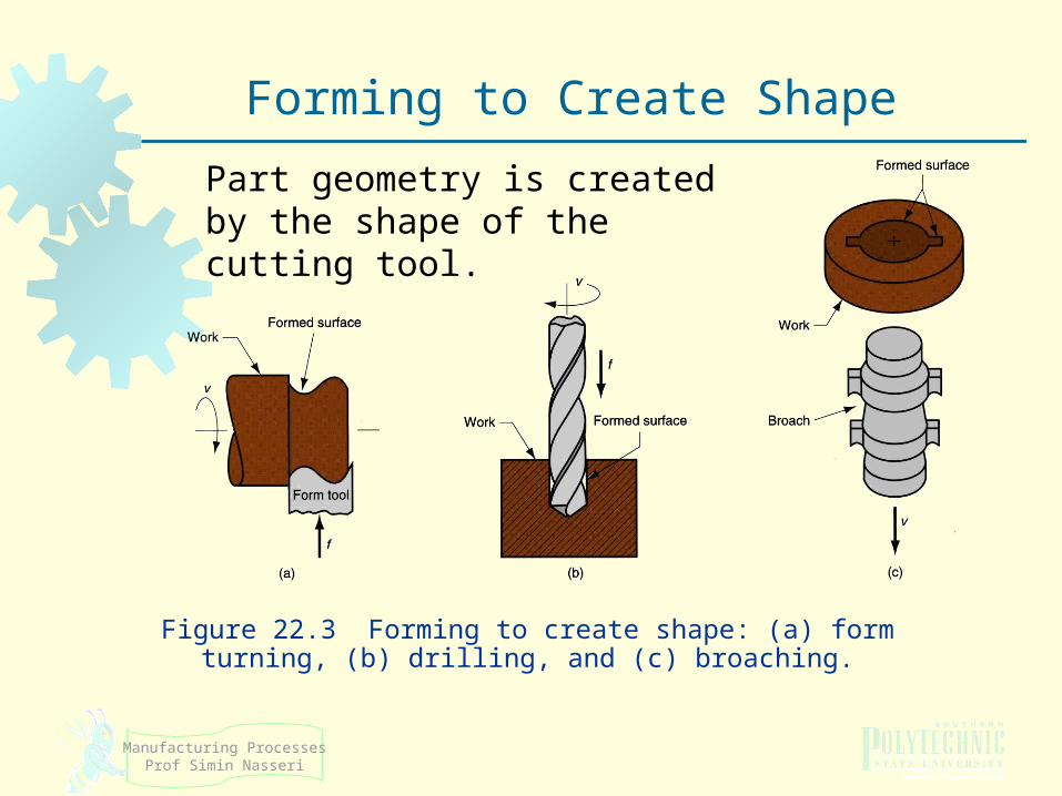
Figure 22.3 Forming to create shape: (a) form turning, (b) drilling, and (c) broaching.
Forming to Create Shape
Part geometry is created by the shape of the cutting tool.
Manufacturing ProcessesProf Simin Nasseri
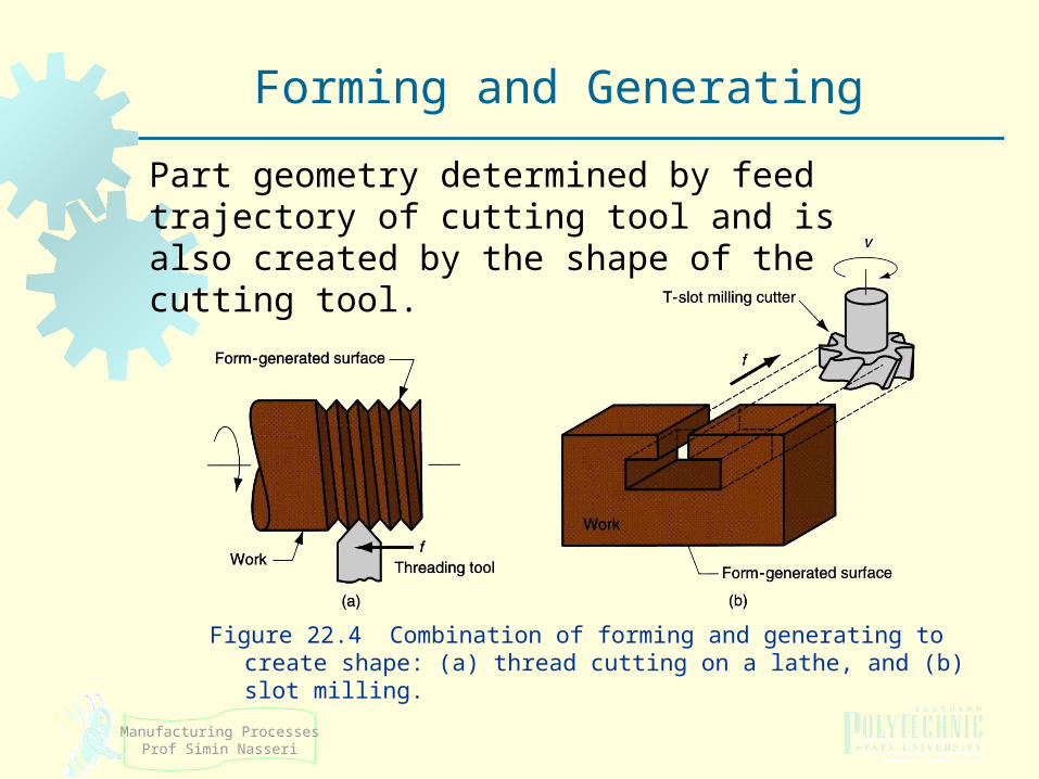
Figure 22.4 Combination of forming and generating to create shape: (a) thread cutting on a lathe, and (b) slot milling.
Forming and Generating
Part geometry determined by feed trajectory of cutting tool and is also created by the shape of the cutting tool.
Manufacturing ProcessesProf Simin Nasseri
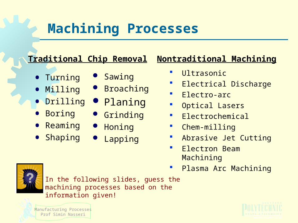
Machining Processes
• Turning
• Milling
• Drilling
• Boring
• Reaming
• Shaping
Ultrasonic Electrical Discharge Electro-arc Optical Lasers Electrochemical Chem-milling Abrasive Jet Cutting Electron Beam Machining Plasma Arc Machining
Traditional Chip Removal
Sawing Broaching
Planing Grinding Honing Lapping
Nontraditional Machining
In the following slides, guess the machining processes based on the information given!
11
Conventional Machining
Manufacturing ProcessesProf Simin Nasseri
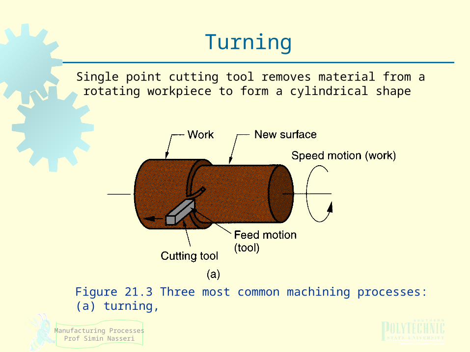
Single point cutting tool removes material from a rotating workpiece to form a cylindrical shape
Figure 21.3 Three most common machining processes: (a) turning,
Turning
Manufacturing ProcessesProf Simin Nasseri
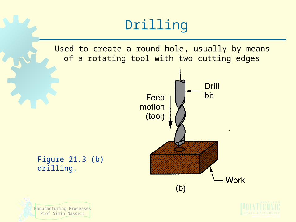
Used to create a round hole, usually by means of a rotating tool with two cutting edges
Figure 21.3 (b) drilling,
Drilling
Manufacturing ProcessesProf Simin Nasseri
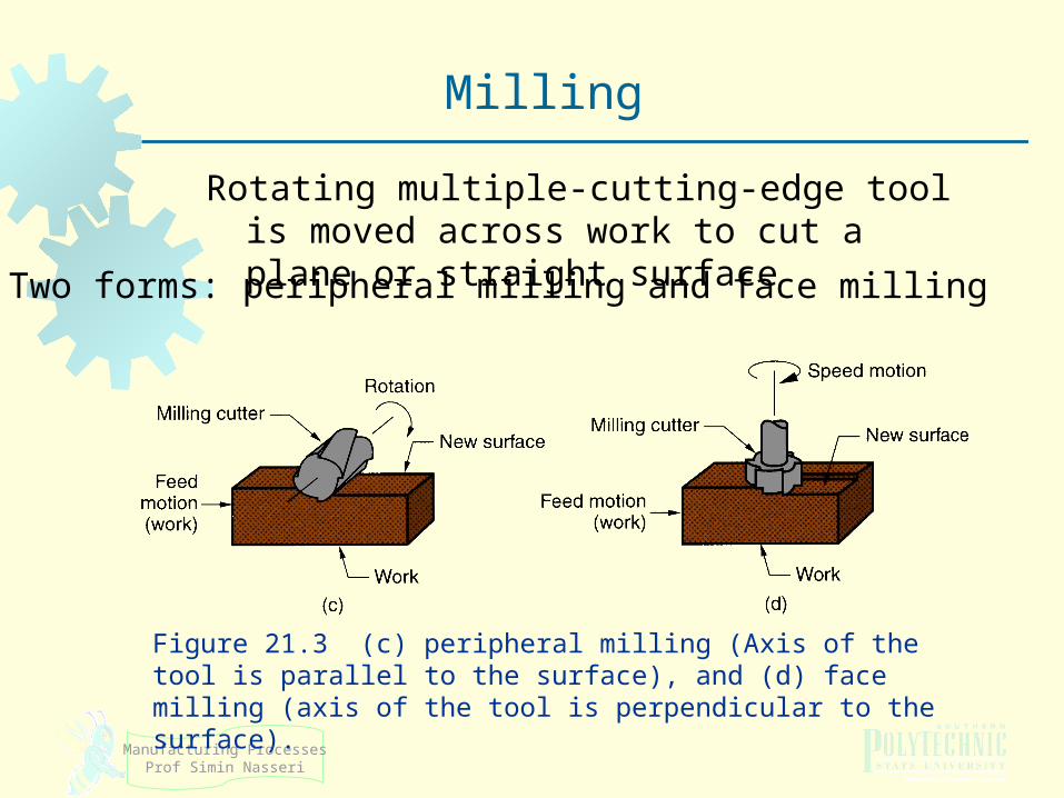
Rotating multiple-cutting-edge tool is moved across work to cut a plane or straight surface
Figure 21.3 (c) peripheral milling (Axis of the tool is parallel to the surface), and (d) face milling (axis of the tool is perpendicular to the surface).
Milling
Two forms: peripheral milling and face milling
Manufacturing ProcessesProf Simin Nasseri
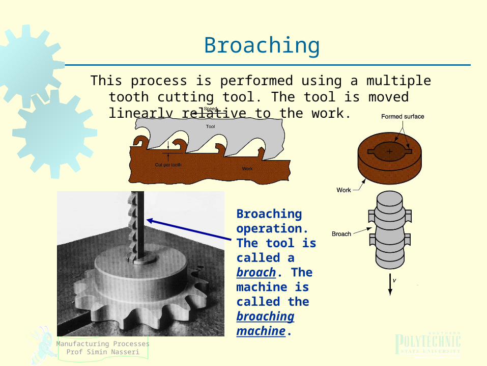
This process is performed using a multiple tooth cutting tool. The tool is moved linearly relative to the work.
Broaching
Broaching operation.The tool is called a broach. The machine is called the broaching machine.
Manufacturing ProcessesProf Simin Nasseri
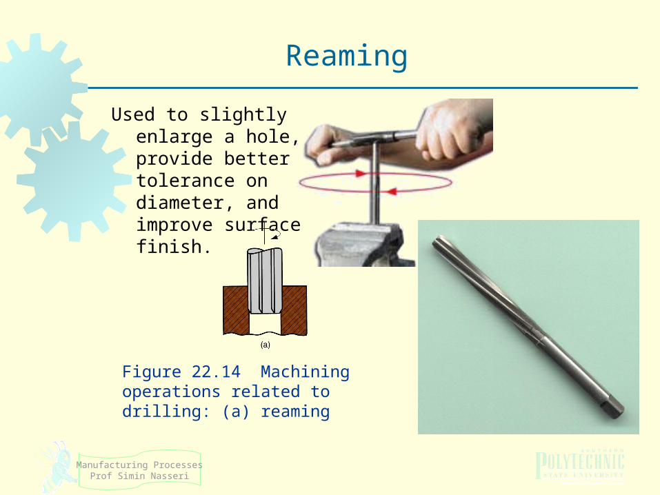
Used to slightly enlarge a hole, provide better tolerance on diameter, and improve surface finish.
Figure 22.14 Machining operations related to drilling: (a) reaming
Reaming
Manufacturing ProcessesProf Simin Nasseri
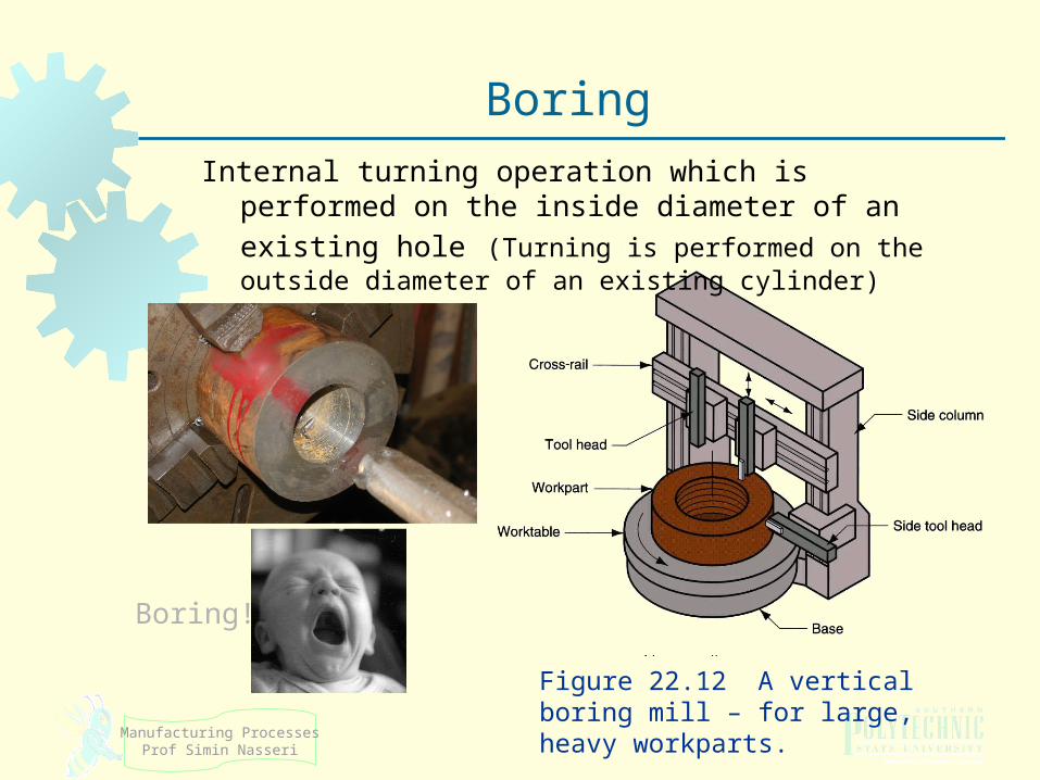
Internal turning operation which is performed on the
inside diameter of an existing hole (Turning is performed on the outside diameter of an existing cylinder)
Boring!
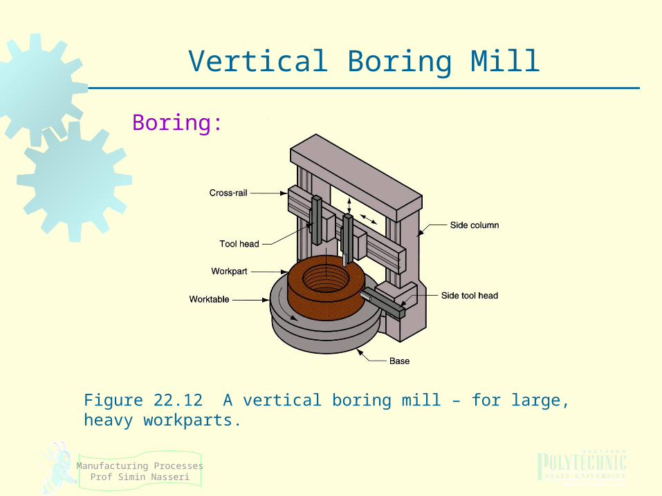
Figure 22.12 A vertical boring mill – for large, heavy workparts.
Boring
Manufacturing ProcessesProf Simin Nasseri
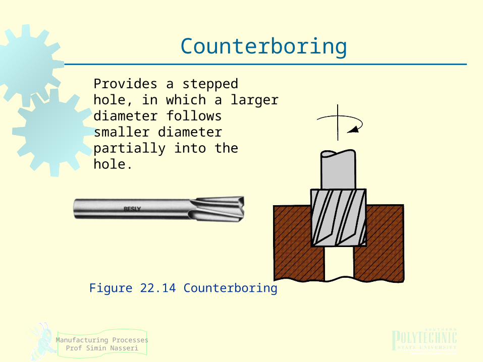
Counterboring
Provides a stepped hole, in which a larger diameter follows smaller diameter partially into the hole.
Figure 22.14 Counterboring
Manufacturing ProcessesProf Simin Nasseri
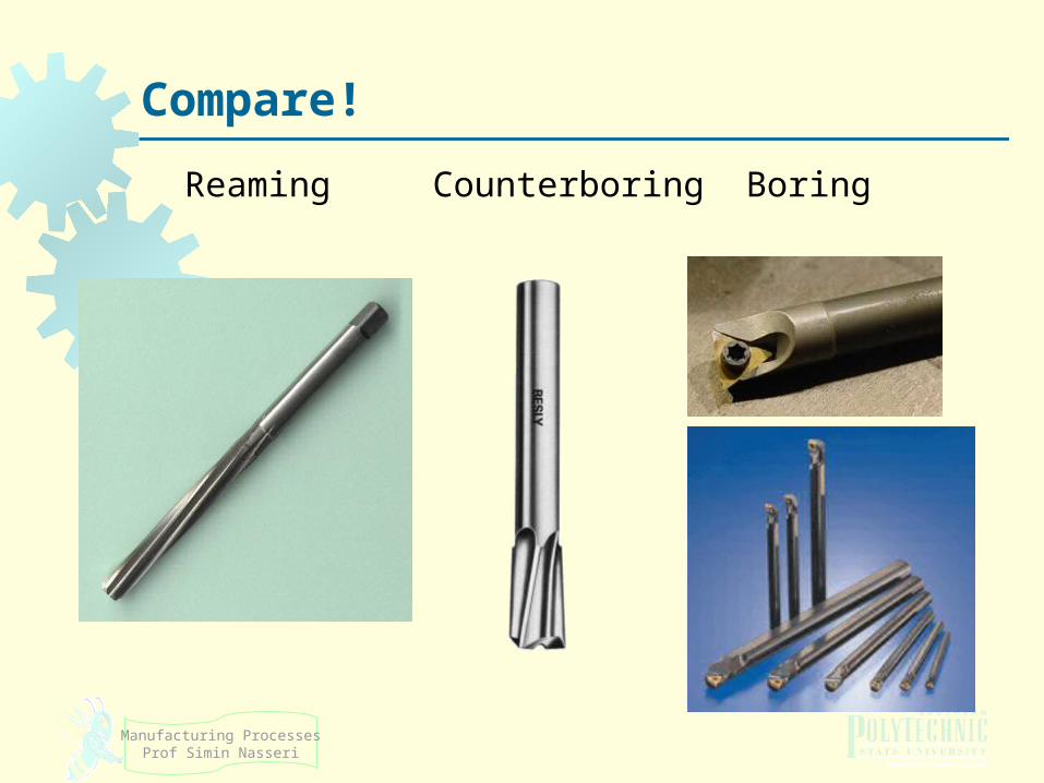
Compare!
ReamingCounterboring Boring
Manufacturing ProcessesProf Simin Nasseri
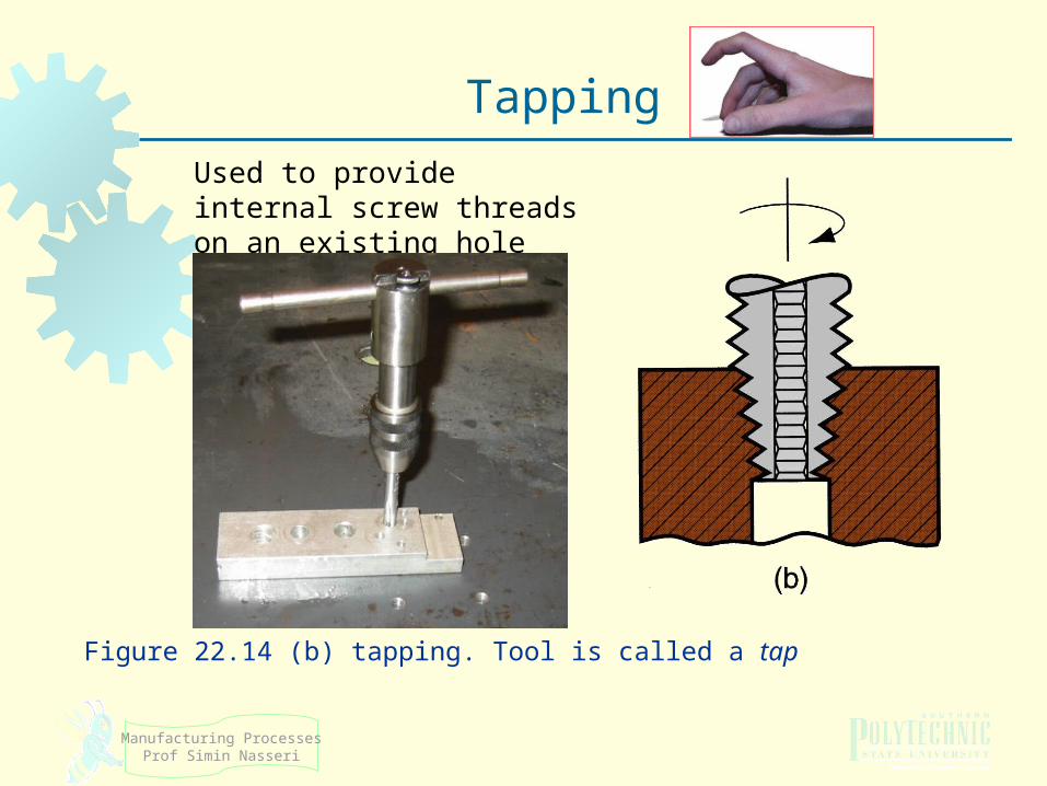
Figure 22.14 (b) tapping. Tool is called a tap
Tapping
Used to provide internal screw threads on an existing hole
Manufacturing ProcessesProf Simin Nasseri
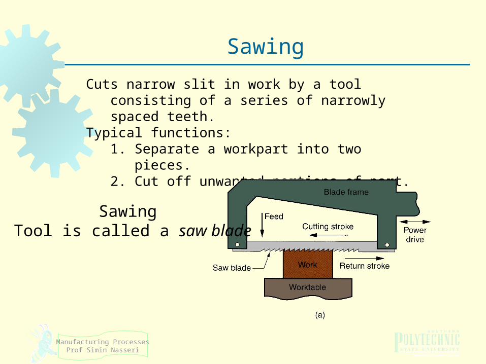
Sawing
Cuts narrow slit in work by a tool consisting of a series of narrowly spaced teeth.
Typical functions:1. Separate a workpart into two pieces. 2. Cut off unwanted portions of part.
Sawing Tool is called a saw blade
Manufacturing ProcessesProf Simin Nasseri
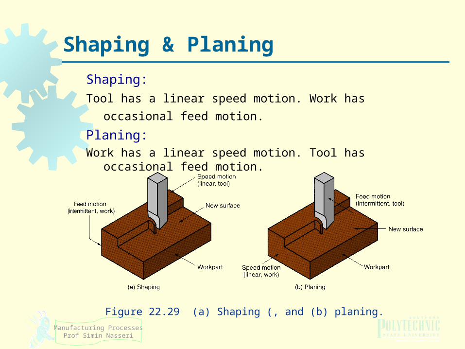
Shaping & Planing
Shaping:
Tool has a linear speed motion. Work has occasional feed motion. Planing:Work has a linear speed motion. Tool has occasional feed motion.
Figure 22.29 (a) Shaping (, and (b) planing.
23
Machinery
In the following slides, guess the name of each machine based on the machining operation!
Manufacturing ProcessesProf Simin Nasseri
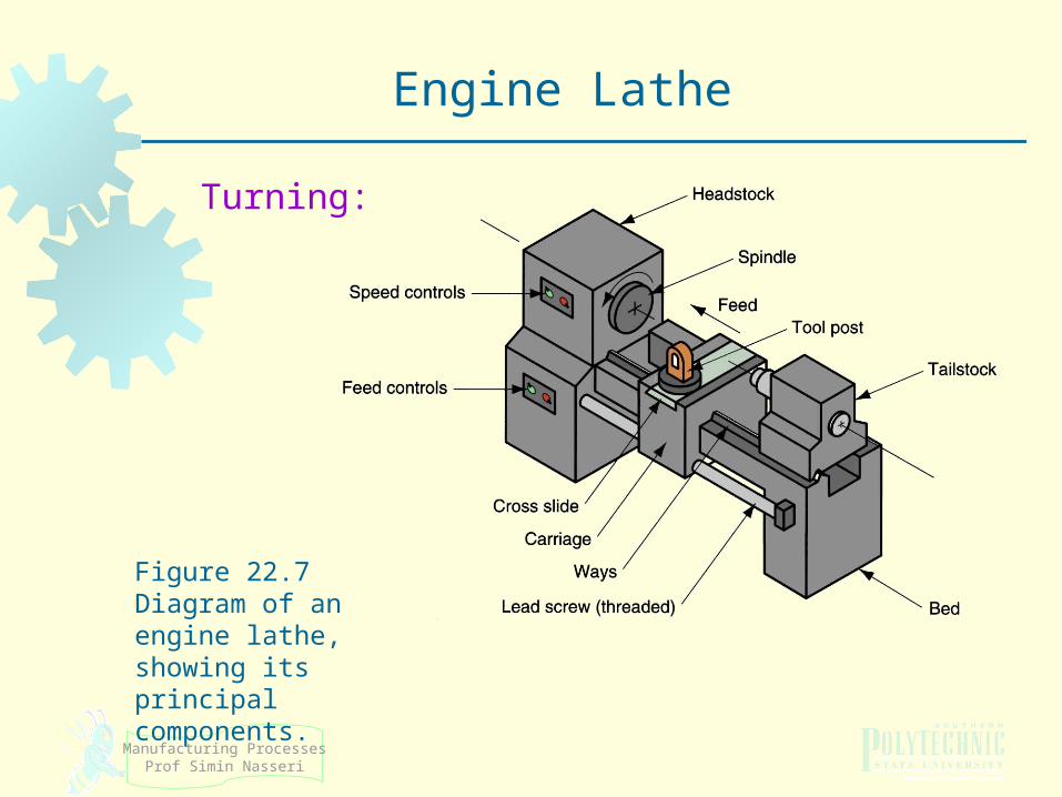
Figure 22.7 Diagram of an engine lathe, showing its principal components.
Engine Lathe
Turning:
Manufacturing ProcessesProf Simin Nasseri
Figure 22.12 A vertical boring mill – for large, heavy workparts.
Vertical Boring Mill
Boring:
Manufacturing ProcessesProf Simin Nasseri
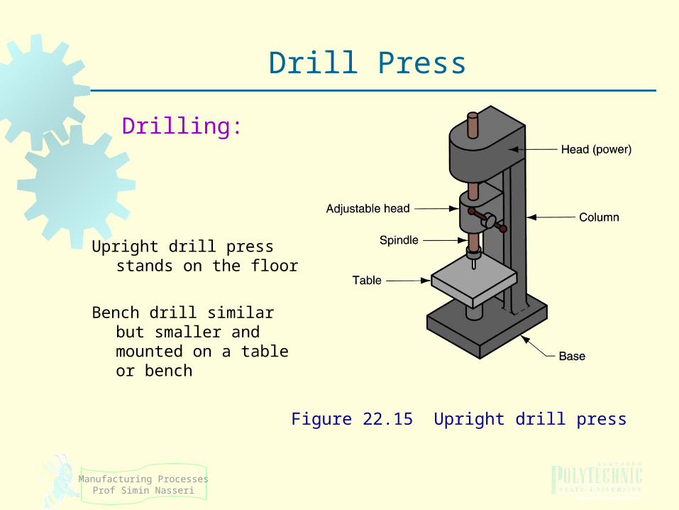
Upright drill press stands on the floor
Bench drill similar but smaller and mounted on a table or bench
Figure 22.15 Upright drill press
Drill Press
Drilling:
Manufacturing ProcessesProf Simin Nasseri
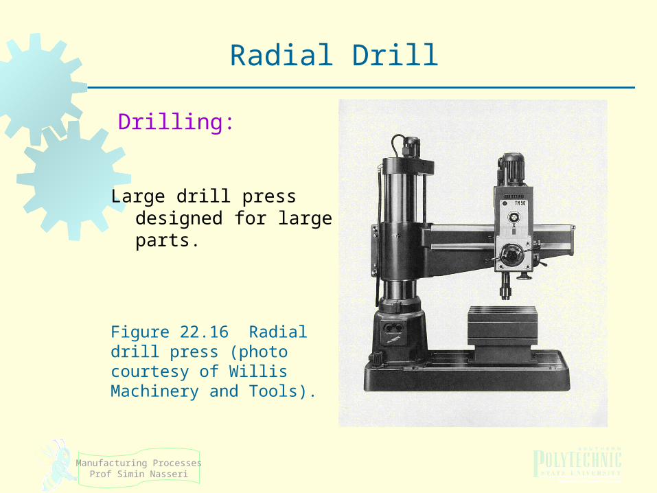
Large drill press designed for large parts.
Figure 22.16 Radial drill press (photo courtesy of Willis Machinery and Tools).
Radial Drill
Drilling:
Manufacturing ProcessesProf Simin Nasseri
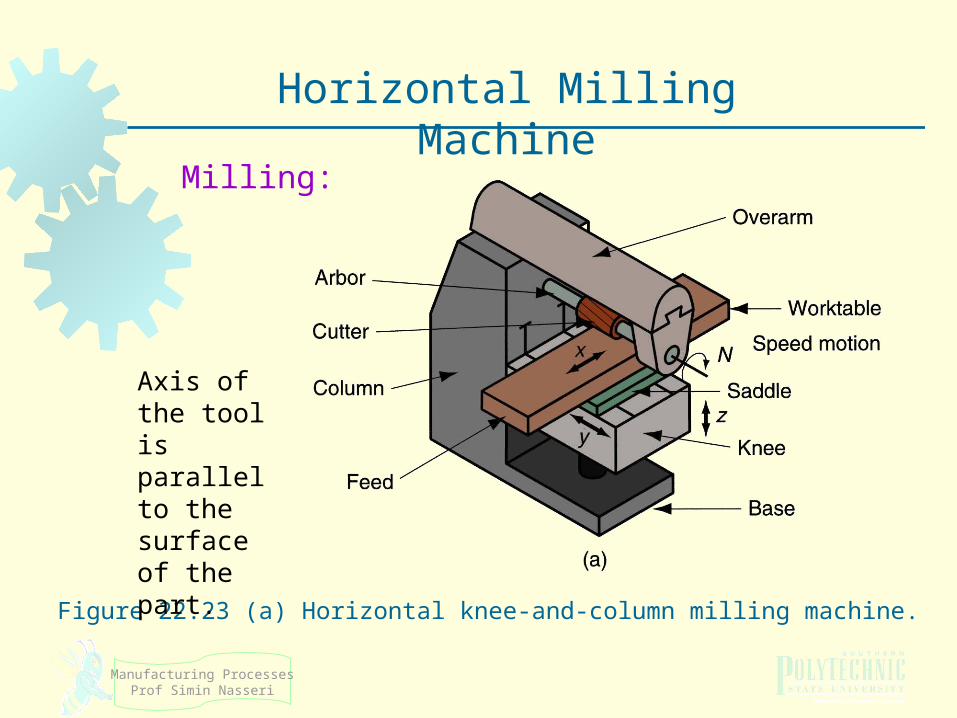
Figure 22.23 (a) Horizontal knee-and-column milling machine.
Horizontal Milling Machine
Axis of the tool is parallel to the surface of the part.
Milling:
Manufacturing ProcessesProf Simin Nasseri
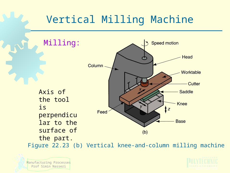
Figure 22.23 (b) Vertical knee‑and‑column milling machine
Vertical Milling Machine
Axis of the tool is perpendicular to the surface of the part.
Milling:
Manufacturing ProcessesProf Simin Nasseri
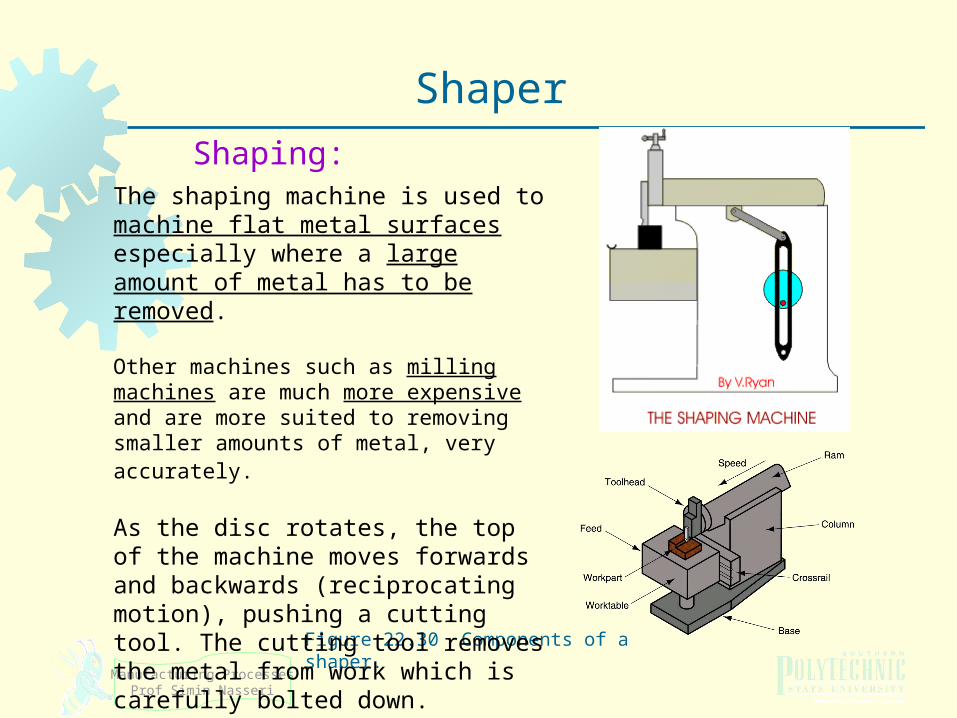
Figure 22.30 Components of a shaper.
Shaper
Shaping:The shaping machine is used to machine flat metal surfaces especially where a large amount of metal has to be removed.
Other machines such as milling machines are much more expensive and are more suited to removing smaller amounts of metal, very accurately.
As the disc rotates, the top of the machine moves forwards and backwards (reciprocating motion), pushing a cutting tool. The cutting tool removes the metal from work which is carefully bolted down.
Manufacturing ProcessesProf Simin Nasseri
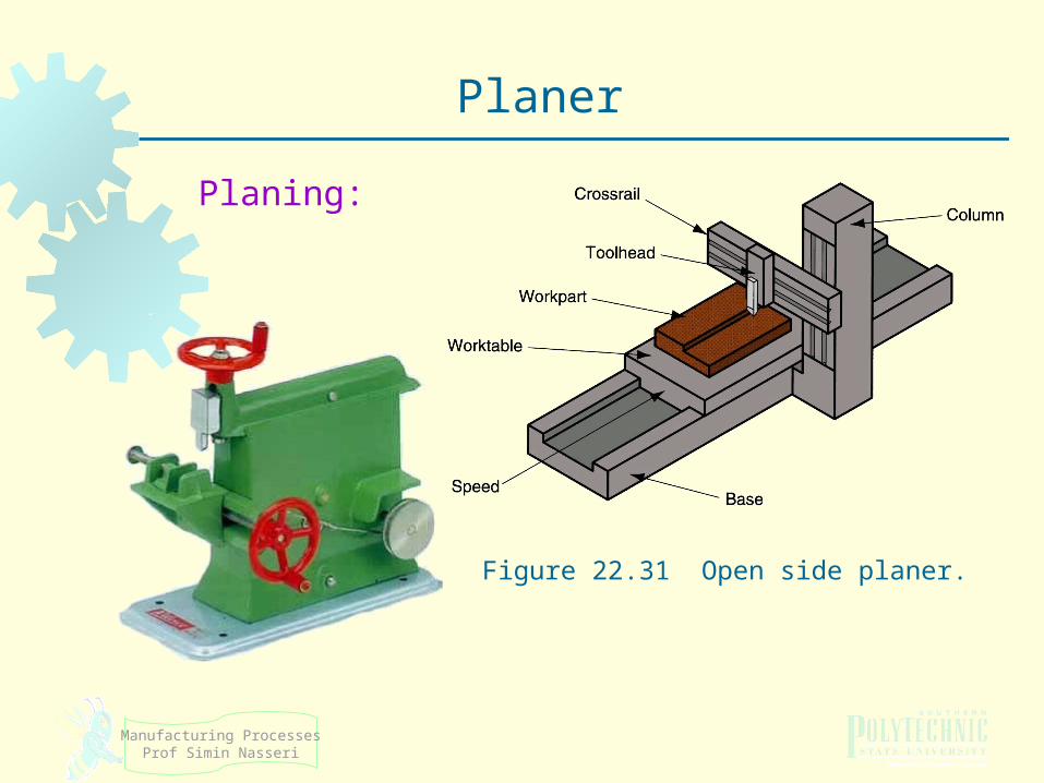
Figure 22.31 Open side planer.
Planer
Planing:
Manufacturing ProcessesProf Simin Nasseri
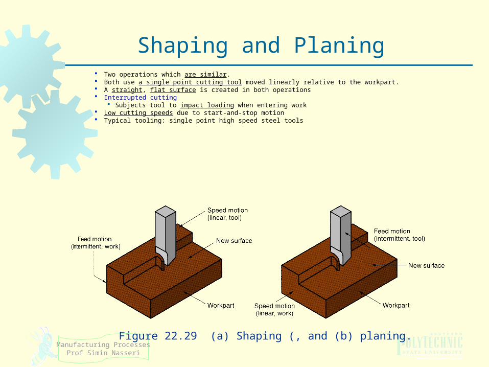
Two operations which are similar. Both use a single point cutting tool moved linearly relative to the workpart. A straight, flat surface is created in both operations Interrupted cutting
Subjects tool to impact loading when entering work Low cutting speeds due to start‑and‑stop motion Typical tooling: single point high speed steel tools
Figure 22.29 (a) Shaping (, and (b) planing.
Shaping and Planing
Manufacturing ProcessesProf Simin Nasseri
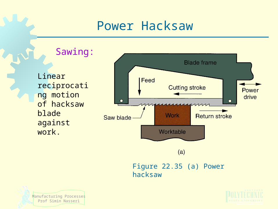
Figure 22.35 (a) Power hacksaw
Power Hacksaw
Sawing:
Linear reciprocating motion of hacksaw blade against work.
Manufacturing ProcessesProf Simin Nasseri
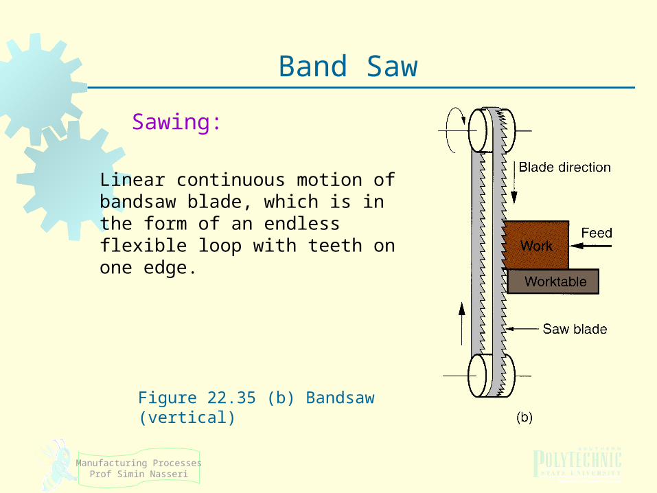
Figure 22.35 (b) Bandsaw (vertical)
Band Saw
Sawing:
Linear continuous motion of bandsaw blade, which is in the form of an endless flexible loop with teeth on one edge.
Manufacturing ProcessesProf Simin Nasseri
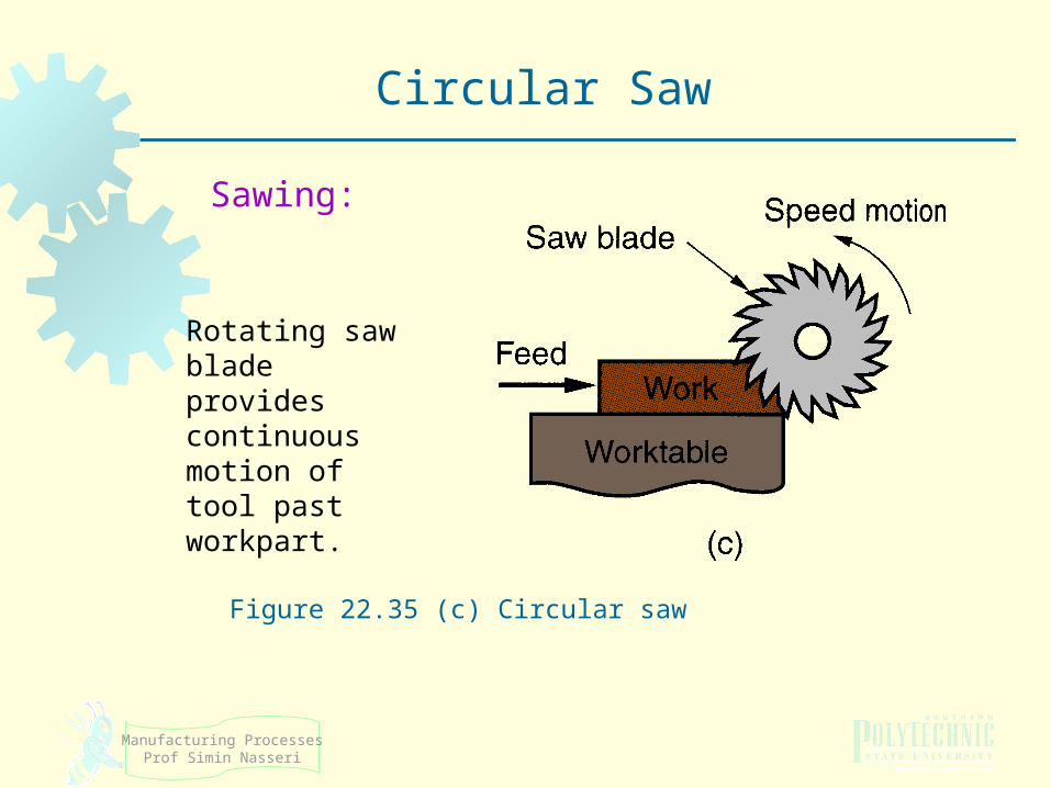
Figure 22.35 (c) Circular saw
Circular Saw
Sawing:
Rotating saw blade provides continuous motion of tool past workpart.
Manufacturing ProcessesProf Simin Nasseri
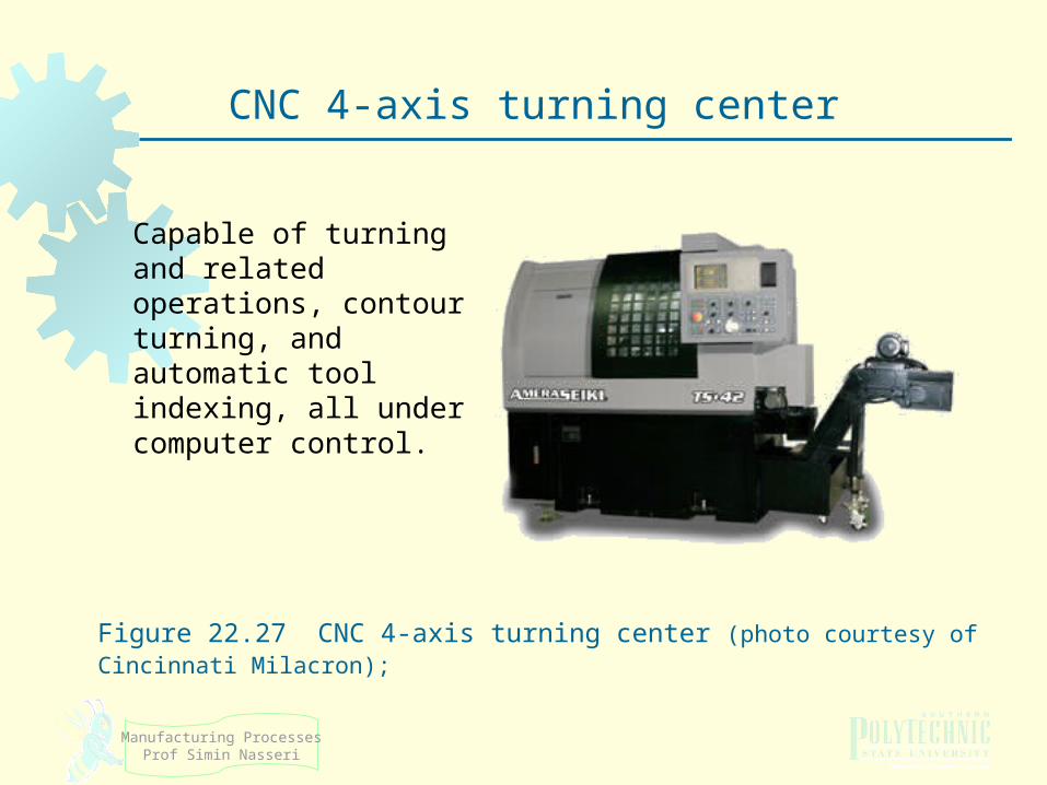
Figure 22.27 CNC 4‑axis turning center (photo courtesy of Cincinnati Milacron);
CNC 4‑axis turning center
Capable of turning and related operations, contour turning, and automatic tool indexing, all under computer control.


