rsc.li/molecular-engineering Molecular Systems Design & Engineering MSDE ISSN 2058-9689 Volume 6 Number 3 1 March 2021 Pages 165–244 REVIEW ARTICLE Joseph R. H. Manning, Siddharth V. Patwardhan et al. Unified mechanistic interpretation of amine-assisted silica synthesis methods to enable design of more complex materials
Transcript
rsc.li/molecular-engineering
Molecular Systems Design & Engineering
MSDE
ISSN 2058-9689
Volume 6Number 31 March 2021Pages 165–244
REVIEW ARTICLEJoseph R. H. Manning, Siddharth V. Patwardhan et al.Unified mechanistic interpretation of amine-assisted silica synthesis methods to enable design of more complex materials
MSDE
REVIEW
Cite this: Mol. Syst. Des. Eng., 2021,
6, 170
Received 14th September 2020,Accepted 15th December 2020
DOI: 10.1039/d0me00131g
rsc.li/molecular-engineering
Unified mechanistic interpretation of amine-assisted silica synthesis methods to enable designof more complex materials
Joseph R. H. Manning, *ab Carlos Brambilaa and Siddharth V. Patwardhan *a
The design of porous sol–gel silica materials is a thriving research field, owing to silica's diversity of
properties and potential applications. Using a variety of additives, most commonly amine-based organic
molecules, several families of silica materials have been developed including silica nanospheres, zeolites,
mesoporous silicas, and bioinspired silicas with controlled particle and pore morphology on multiple length
scales. Despite the wide range of study into these materials, and similarity in terms of reagents and additive
compounds, none can recreate the features and complexity present within naturally occurring biosilica
materials. This is due in part to a lack of ‘joined-up’ thinking during research into silica synthesis strategies
and methodology. Specifically, mechanistic insights gained for one set of conditions or additive structures
(i.e. material types) are not translated to other material types. In order to improve the structural complexity
available in synthetic silica materials, as well as to improve both understanding and synthesis methods for
all silica types, a unified approach to mechanistic understanding of formation in amine-assisted silica
synthesis is required. Accordingly, in this review we analyse contemporary investigations into silica synthesis
mechanism as a function of (amine) additive structure, analysing how they imprint varying levels of order
into the eventual silica structure. We identify four fundamental driving forces through which additives
control silica structure during synthesis: (i) controlling rates of silica precursor hydrolysis and condensation;
(ii) forming charge-matched adducts with silicate ions in solution; (iii) self-assembling into mesophases to
physically template pores; and (iv) confining the location of synthesis into specifically shaped vesicles. We
analyse how each of these effects can be controlled as a function of additive structure, and highlight
recent developments where multiple effects have been harnessed to form synthetic silica materials with
further structural complexity than what was previously possible. Finally, we suggest further avenues of
research which will lead to greater understanding of the structure–function relationship between amine
additives and final materials, hence leading to more complex and high-value silica and other materials.
1. Background
As process engineering evolves, so do the requirements onthe materials used. With increasingly prominent need forcarbon capture and sequestration,1,2 advanced drug deliverysystems,3–6 and next-generation catalysts and supports,7,8
Several families of porous silica materials have been developed including recent bioinspired silicas. Despite the wide range of studies into these materials,and similarity in terms of reagents and additive compounds, none can recreate the features and complexity present within naturally occurring biosilicamaterials. This is due in part to a lack of ‘joined-up’ thinking during research into silica synthesis strategies and methodology. For the first time, wepresent a unified approach to mechanistic understanding of formation in amine-assisted silica synthesis. Using our proposed approach, mechanisticinsights gained from one family of materials can be translated to other material types. This has the potential to improve the structural complexity availablein synthetic silica materials, as well as to improve both understanding and synthesis methods for all silica types. Utilising this unified knowledge, we open-up future avenues of research including experiments and computations, spanning multiple length-scales and production scales, which will lead to greaterunderstanding of the structure–function relationship between amine additives and final materials, hence leading to more complex and high-value silicaand other materials.
more complex material structures and surface chemistriesare required to meet the growing and specific demands. Inorder to achieve this, new synthesis methods for porousmaterials are required and are the subject of significantscientific interest. An excellent example of this is poroussilicas (either amorphous precipitated silicas or crystallinezeolites), a widely used industrial material whose versatilityenables application in sectors ranging from polymer fillers,to acid–base catalysts, pharmaceutical excipients, filtrationmedia and pollutant sorbents.
As with most metal oxides, silicas are generally formedusing sol–gel methods. In general, a monomeric precursore.g. tetraethylorthosilicate (TEOS) is hydrolysed into a silicateanion, which then undergoes dehydration polymerisation
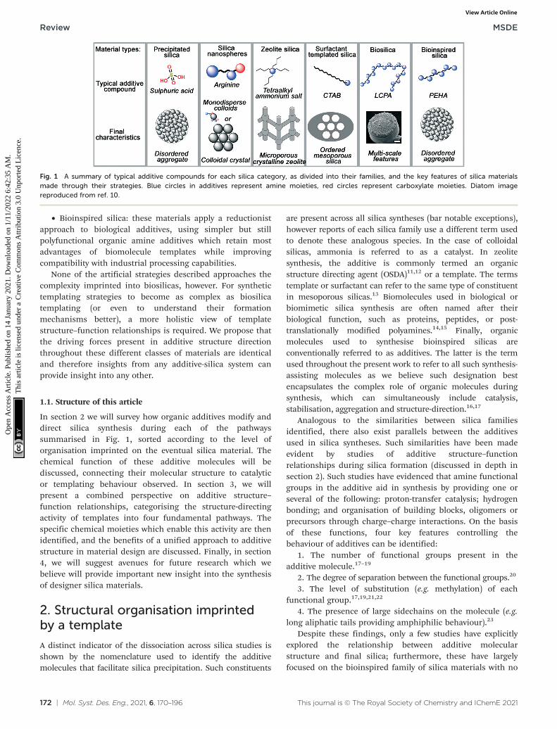
into dimers and trimers, small oligomers, and finallymacromolecular colloidal particles.9 This process isparticularly versatile, providing a rich parameter space forresearchers and manufacturers to control and improve theproperties of the materials. Such modifications are mostlyachieved by introducing organic molecules (termed‘additives’) into the process, which assist in the formationand nanostructuring of the materials. A schematicrepresentation of several silica materials and the additivesused to synthesise them is shown in Fig. 1. As can beobserved, the change in additive structure can result in anentirely different product, even when otherwise similarprocessing conditions are used. Based on such modifications,the following major families of materials have emerged:
• Colloidal silica nanospheres: silica nanospheres, makeuse of small additives like ammonia or monopeptides tocarefully control the rate of silica polymerisation and makemonodisperse silica colloids.
• Zeolites: in a similar fashion to colloidal silicas,templated silica zeolites often use small, charged additiveslike tetraalkylammonium salts to template small pores withincrystalline silicate.
• Surfactant-templated silicas: more complex porosity isintroduced in surfactant-templated amorphous silicas, whichtake advantage the amphiphilic nature of the surfactantadditive (commonly cetyl trimethyl ammonium bromide,CTAB) to imprint larger, liquid-crystal-like pores into the finalstructure.
• Biological silicas: highly complex structures, not seen inany of the above examples, are imprinted in biological silicas,which use the polyfunctionality of proteins and biogeniclong-chain polyamines (LCPAs) to imprint more complexhybrid functionality into silica materials than artificialorganic compounds can provide.
Carlos Brambila
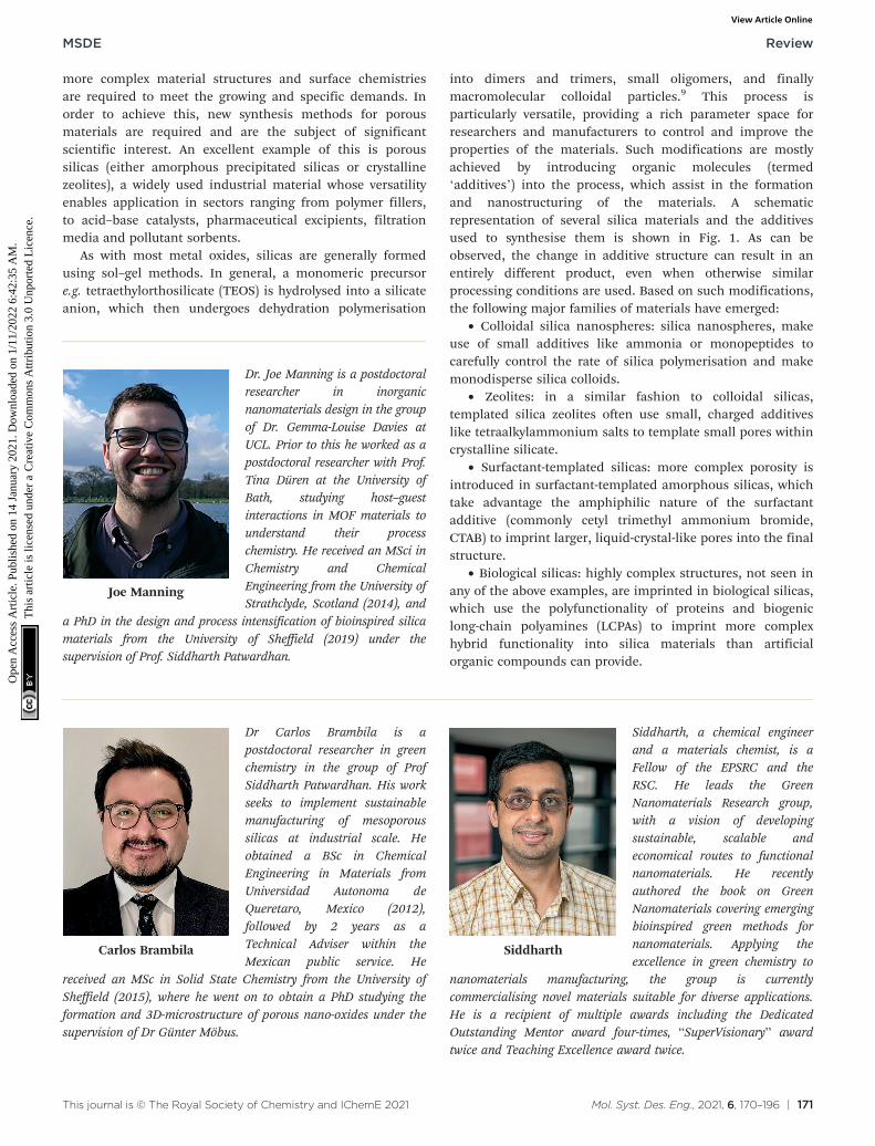
Dr Carlos Brambila is apostdoctoral researcher in greenchemistry in the group of ProfSiddharth Patwardhan. His workseeks to implement sustainablemanufacturing of mesoporoussilicas at industrial scale. Heobtained a BSc in ChemicalEngineering in Materials fromUniversidad Autonoma deQueretaro, Mexico (2012),followed by 2 years as aTechnical Adviser within theMexican public service. He
received an MSc in Solid State Chemistry from the University ofSheffield (2015), where he went on to obtain a PhD studying theformation and 3D-microstructure of porous nano-oxides under thesupervision of Dr Günter Möbus.
Siddharth
Siddharth, a chemical engineerand a materials chemist, is aFellow of the EPSRC and theRSC. He leads the GreenNanomaterials Research group,with a vision of developingsustainable, scalable andeconomical routes to functionalnanomaterials. He recentlyauthored the book on GreenNanomaterials covering emergingbioinspired green methods fornanomaterials. Applying theexcellence in green chemistry to
nanomaterials manufacturing, the group is currentlycommercialising novel materials suitable for diverse applications.He is a recipient of multiple awards including the DedicatedOutstanding Mentor award four-times, “SuperVisionary” awardtwice and Teaching Excellence award twice.
Joe Manning
Dr. Joe Manning is a postdoctoralresearcher in inorganicnanomaterials design in the groupof Dr. Gemma-Louise Davies atUCL. Prior to this he worked as apostdoctoral researcher with Prof.Tina Düren at the University ofBath, studying host–guestinteractions in MOF materials tounderstand their processchemistry. He received an MSci inChemistry and ChemicalEngineering from the University ofStrathclyde, Scotland (2014), and
a PhD in the design and process intensification of bioinspired silicamaterials from the University of Sheffield (2019) under thesupervision of Prof. Siddharth Patwardhan.
• Bioinspired silica: these materials apply a reductionistapproach to biological additives, using simpler but stillpolyfunctional organic amine additives which retain mostadvantages of biomolecule templates while improvingcompatibility with industrial processing capabilities.
None of the artificial strategies described approaches thecomplexity imprinted into biosilicas, however. For synthetictemplating strategies to become as complex as biosilicatemplating (or even to understand their formationmechanisms better), a more holistic view of templatestructure–function relationships is required. We propose thatthe driving forces present in additive structure directionthroughout these different classes of materials are identicaland therefore insights from any additive-silica system canprovide insight into any other.
1.1. Structure of this article
In section 2 we will survey how organic additives modify anddirect silica synthesis during each of the pathwayssummarised in Fig. 1, sorted according to the level oforganisation imprinted on the eventual silica material. Thechemical function of these additive molecules will bediscussed, connecting their molecular structure to catalyticor templating behaviour observed. In section 3, we willpresent a combined perspective on additive structure–function relationships, categorising the structure-directingactivity of templates into four fundamental pathways. Thespecific chemical moieties which enable this activity are thenidentified, and the benefits of a unified approach to additivestructure in material design are discussed. Finally, in section4, we will suggest avenues for future research which webelieve will provide important new insight into the synthesisof designer silica materials.
2. Structural organisation imprintedby a template
A distinct indicator of the dissociation across silica studies isshown by the nomenclature used to identify the additivemolecules that facilitate silica precipitation. Such constituents
are present across all silica syntheses (bar notable exceptions),however reports of each silica family use a different term usedto denote these analogous species. In the case of colloidalsilicas, ammonia is referred to as a catalyst. In zeolitesynthesis, the additive is commonly termed an organicstructure directing agent (OSDA)11,12 or a template. The termstemplate or surfactant can refer to the same type of constituentin mesoporous silicas.13 Biomolecules used in biological orbiomimetic silica synthesis are often named after theirbiological function, such as proteins, peptides, or post-translationally modified polyamines.14,15 Finally, organicmolecules used to synthesise bioinspired silicas areconventionally referred to as additives. The latter is the termused throughout the present work to refer to all such synthesis-assisting molecules as we believe such designation bestencapsulates the complex role of organic molecules duringsynthesis, which can simultaneously include catalysis,stabilisation, aggregation and structure-direction.16,17
Analogous to the similarities between silica familiesidentified, there also exist parallels between the additivesused in silica syntheses. Such similarities have been madeevident by studies of additive structure–functionrelationships during silica formation (discussed in depth insection 2). Such studies have evidenced that amine functionalgroups in the additive aid in synthesis by providing one orseveral of the following: proton-transfer catalysis; hydrogenbonding; and organisation of building blocks, oligomers orprecursors through charge–charge interactions. On the basisof these functions, four key features controlling thebehaviour of additives can be identified:
1. The number of functional groups present in theadditive molecule.17–19
2. The degree of separation between the functional groups.20
3. The level of substitution (e.g. methylation) of eachfunctional group.17,19,21,22
4. The presence of large sidechains on the molecule (e.g.long aliphatic tails providing amphiphilic behaviour).23
Despite these findings, only a few studies have explicitlyexplored the relationship between additive molecularstructure and final silica; furthermore, these have largelyfocused on the bioinspired family of silica materials with no
Fig. 1 A summary of typical additive compounds for each silica category, as divided into their families, and the key features of silica materialsmade through their strategies. Blue circles in additives represent amine moieties, red circles represent carboxylate moieties. Diatom imagereproduced from ref. 10.
equivalent systematic studies being performed for silicananospheres, zeolites, or surfactant templated silicas.
The present work addresses the lack of such studiesoutside bioinspired silicas by surveying previous scientificstudies of additive-assisted silica synthesis. Specifically, weoutline the different levels of structural organisation whichcan be imprinted onto the various families of silica materialsby organic additives as a result of the features present on theadditive itself. Such behaviour results in structuralorganisation of the eventual silica materials, thedimensionality of which is a result of the additive structure:
1. 0-D involves control over anisotropic morphologicalproperties such as particle size or pore imprinting in theshape of the additive molecule itself.
2. 1-D organisation involves isotropic ordering in a singledirection only such as through the creation of oriented poreswithin otherwise uncontrolled nanoparticles.
3. 2-D control generally takes place by simultaneouslycombining aspects of 0d and 1d organisation, e.g. byproducing ordered porosity in particles of controlled size.
4. 3-D templating consists of control over internalporosity and particle size in multiple directions andlength scales.
2.1. No order
2.1.1. Silica synthesis without additives. Beforeapproaching the order-imprinting phenomena involvedduring sol–gel syntheses, it is relevant to consider theconditions and additives which can lead to the absence oforder in silica materials. There exist many excellent reviewson the exact science of silica polymerisation from themolecular level24,25 up to large particles9 and industrialmaterials.26 Herein we will summarise some of the key pointsin relation to the formation mechanisms.
Even without recourse to organic molecules to controlsilica polymerisation and growth, it is possible to modulatethe rate of hydrolysis and condensation on a number oflength scales by carefully controlling the concentration ofinorganic bases in solution. Combined, these studies enablea significant degree of understanding regarding whichprocesses are of critical importance to the overallpolymerisation in the absence of organic additives. Theyalso provide a good benchmark for understanding howorganic molecules can modulate the polymerisationtransition states and oligomerisation kinetics to modifysilica structure.
Control of silica polymerisation can be achieved bybalancing the rates of precursor hydrolysis (khyd, eqn (1)) andcondensation (kcond eqn (2)), enabling growth of eithermonodisperse spherical silica “sols,” porous gel networks, orporous precipitated aggregates.9 These two reactions are bothaccelerated by proton-transfer catalysis,27,28 i.e. acidic orbasic dissolved species. Therefore, control over the extent,timing and relative rates of these two processes are highlydependent on solution conditions during synthesis.
Si OEtð Þ4 þH2O → HOSi OEtð Þ3 þ EtOH →→ Si OHð Þ4 þ 4EtOH (1)
2Si(OH)4 → (HO)3Si–O–Si(OH)3 + H2O (2)
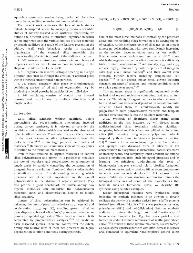
One of the most direct methods of controlling the processesabove and the resulting silica formation is by varying the pHof reaction. At the isoelectric point of silica (ca. pH 2) there isalmost no polymerisation, with rates significantly increasingas the solution becomes either more or less acidic.25
Polymerisation rates reach a maximum at ca. pH 7, abovewhich the negative charge on silica monomers is sufficientlyhigh to retard condensation.25 Additionally, khyd and kcondare also highly influenced by both the presence of inorganicsalts (e.g. alkali metal halides)29 and their overall ionicstrength. Further factors including temperature, saltspecies,30–32 Si : salt species molar ratio, solvent dielectricconstant, presence of catalysts, and mixing conditions leadsto a wide parameter space.24,33
This parameter space is significantly augmented by theinclusion of organic molecules containing basic (i.e. amino)moieties. The ability of organic amines to adopt a range ofhard and soft base behaviour dependent on overall molecularstructure allows them to simultaneously modify theprogression of silica polymerisation reactions and templateordered structural motifs into the resultant materials.
2.1.2. Synthesis of disordered silicas using amineadditives. In the first instance, we will discuss amineadditive-induced silica formation without significanttemplating behaviour. This is best exemplified by bioinspiredsilica (BIS) materials using organic polyamine moleculeinspired by those found in biosilicas (reviewed in section2.5).34 Biosilica formation in living organisms like diatomsand sponges uses dissolved form of silicates at lowconcentration to biosynthesise hierarchical porous structuresof amazing beauty and complexity under ambient conditions.Drawing inspiration from such biological processes and bylearning the principles underpinning the roles ofbiomolecules that play a critical role in biosilica formation,synthesis routes to rapidly produce BIS at room temperature,in water were recently developed.35 BIS approach usesorganic ‘additives’ whose structure and function mimics thebiological structures of some of the biomolecules thatfacilitate biosilica formation. Below, we describe BISsynthesis using selected examples.
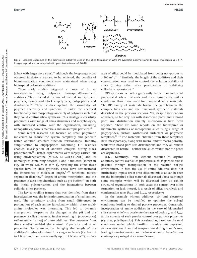
Earlier bioinspired materials were synthesised usingbiological or synthetic polymers in an attempt to directlyreplicate the activity of a peptide derived from silaffin proteinsisolated from diatom biosilica.36 This was performed by usingpoly(L-lysine) (PLL) and poly(allylamine) (PAA) as syntheticadditives to mimic the length and multifunctionality ofbiomolecular templates (see Fig. 2a); silica particles wereformed in under 5 minutes reminiscent of silaffin-precipitatedsilica.37,38 For both of these additive molecules, BIS was formedas polydisperse spherical particles with little increase in surfacearea compared to equivalent NaCl-templated control silicas
(albeit with larger pore sizes).39 Although the long-range orderobserved in diatoms was yet to be achieved, the benefits ofbiomineralization conditions were maintained when usingbioinspired polymeric additives.
These early studies triggered a range of furtherinvestigations using polymeric bioinspired/biomimeticadditives. These included the use of natural and syntheticpolymers, homo- and block co-polymers, polypeptides anddendrimers.16 These studies applied the knowledge ofpolymer chemistry and synthesis to tailor the chemicalfunctionality and morphology/assembly of polymers such thatthey could control silica synthesis. This strategy successfullyproduced a wide range of silica structures and morphologies,with increased control over the organisation, includingnanoparticles, porous materials and anisotropic particles.40
Some recent research has focused on small polyaminemolecules to reduce the system complexity and generatebetter additive structure–function relationships. Initially,simplification to oligopeptides containing 1–5 residuesenabled investigation of additive catalysis during silicaprecipitation.41 Further experiments were largely carried outusing ethylenediamine (MEDA, NH2CH2CH2NH2) and itshomologues containing between 2 and 7 moieties (shown inFig. 2b where MEDA is n = 1), revealing the effect thesespecies have on silica synthesis. These have demonstratedthe importance of molecular length,17,18 functional moietyseparation distance,20 degree of amine methylation, and thepresence of assisting chemicals such as pH buffers22 on boththe initial polymerisation and the interactions betweencolloidal silica particles.
The key controlling feature that was identified from theseinvestigations was the ionisation/protonation of small aminesused. The complexity arising from small differences inprotonation of each amine functionality within these multi-amine molecules was interesting. This led to dynamicchanges with respect to the changes in the pH and thepresence of silica precursor, further resulting in (co-operative)self-assembly (or not) of these additives. The outcomes fromthese studies enabled the control of porosity and otherproperties. For example, by changing the length of theadditives/number of amines in a single molecule (i.e. from 2to 7 N atoms,17 and occasionally up to 18 N atoms42), surface
area of silica could be modulated from being non-porous to>300 m3 g−1.17 Similarly, the length of the additives and theirconcentration was used to control the solution stability ofsilica (driving either silica precipitation or stabilisingcolloidal suspensions).18
BIS synthesis is both significantly faster than industrialprecipitated silica materials and uses significantly milderconditions than those used for templated silica materials.The BIS family of materials bridge the gap between thecomplex biosilicas and the functional synthetic materialsdescribed in the previous sections. Yet, despite tremendousadvances, so far only BIS with disordered pores and a broadpore size distribution (mainly microporous) have beenreported. There are some reports on the bioinspired orbiomimetic synthesis of mesoporous silica using a range ofpolypeptides, custom synthesised surfactant or polymerictemplates.43–46 The materials obtained from these templateshave mesoporosity, along with micro- and/or macro-porosity,while with broad pore size distributions and they all remaindisordered in nature – neither the silica “walls” nor the poresare organised.
2.1.3. Summary. Even without recourse to organicadditives, control over silica properties such as particle size ispossible through manipulation of the reaction sol–gelenvironment. In fact, the use of amine additives does notintrinsically impose order onto silica materials, as can be seenfor the bioinspired silica materials discussed above (althoughsome examples which will be discussed later do exhibitstructural organisation). In both cases the control over silicaformation, or lack thereof, is a result of silica hydrolysis andcondensation rates (khyd and kcond, respectively).
In the example without additives, pH and electrolyteenvironment can be modified to optimise the sol–gelconditions leading to desired particle properties. Conversely,incorporation of amine additives in the case of bioinspiredsilica serves chiefly to accelerate the rates of both khyd and kcondat the expense of such precise control over particle properties(e.g. size, polydispersity). This acceleration, based on the mildconditions under which biosilica materials are deposited,reduces reaction times and temperatures during manufacture,leading to environmental and technoeconomical benefits overcontemporary sol–gel silica manufacture.
Fig. 2 Selected examples of the bioinspired additives used in the silica formation in vitro (A) synthetic polymers and (B) small molecules (n = 1–7).Images reproduced or adapted with permission from ref. 16–18.
Exploration of different additive chemical structures hasalso led to control over a wider range of silica properties thanare possible in the additive-free system, such as the imprintingof disordered internal mesopores or formation of hollowparticles. Notwithstanding the disorder introduced throughaccelerated khyd and kcond, this finding clearly demonstratesthat changing the chemical structure of additives is an effectivestrategy for tailoring the properties of silica materials. To besttake advantage of including amine additives in silica synthesismethods, the connection between additive structure andreaction progression (both in terms of khyd and kcond and otherstructure-directing effects) must be fully understood.
2.2. 0-Dimensional structural ordering
Whereas BIS materials are generally synthesised at circum-neutral pH with catalytically active amine additives, materialswith imprinted order are generally synthesised under muchless reactive conditions. In these cases, silica formation fromalkoxysilane and other precursors is commonly induced bymonofunctional isotropic templates such as ammonia andtetramethylammonium ions. This process can result in twodistinct material types, monodisperse colloidal nanospheresand zeolite silicas. In both cases, the properties of thematerial can be effectively controlled by varying the structureand concentration of the additive as well as the reactionconditions.
2.2.1. Basic amine molecules forming monodisperse silicananospheres. The simplest possible additive molecule isammonia which, similarly to the inorganic base catalysedsystem described in section 2.1.1, is chiefly used for
producing colloidal silica nanospheres. This “Stöber” processproduces stable silica nanospheres (SNS) in suspension withunusually high monodispersity and stability with diametersranging from tens to hundreds of nanometres.
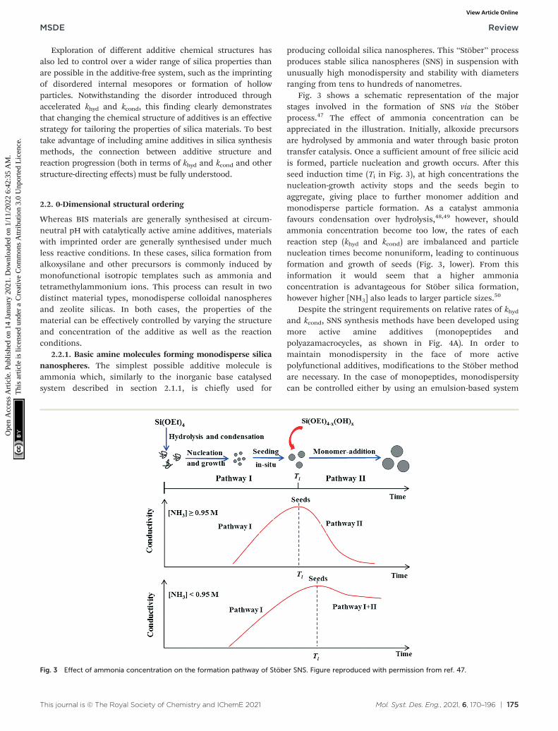
Fig. 3 shows a schematic representation of the majorstages involved in the formation of SNS via the Stöberprocess.47 The effect of ammonia concentration can beappreciated in the illustration. Initially, alkoxide precursorsare hydrolysed by ammonia and water through basic protontransfer catalysis. Once a sufficient amount of free silicic acidis formed, particle nucleation and growth occurs. After thisseed induction time (Ti in Fig. 3), at high concentrations thenucleation-growth activity stops and the seeds begin toaggregate, giving place to further monomer addition andmonodisperse particle formation. As a catalyst ammoniafavours condensation over hydrolysis,48,49 however, shouldammonia concentration become too low, the rates of eachreaction step (khyd and kcond) are imbalanced and particlenucleation times become nonuniform, leading to continuousformation and growth of seeds (Fig. 3, lower). From thisinformation it would seem that a higher ammoniaconcentration is advantageous for Stöber silica formation,however higher [NH3] also leads to larger particle sizes.50
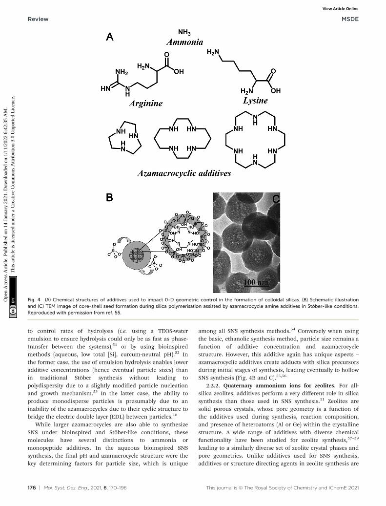
Despite the stringent requirements on relative rates of khydand kcond, SNS synthesis methods have been developed usingmore active amine additives (monopeptides andpolyazamacrocycles, as shown in Fig. 4A). In order tomaintain monodispersity in the face of more activepolyfunctional additives, modifications to the Stöber methodare necessary. In the case of monopeptides, monodispersitycan be controlled either by using an emulsion-based system
Fig. 3 Effect of ammonia concentration on the formation pathway of Stöber SNS. Figure reproduced with permission from ref. 47.
to control rates of hydrolysis (i.e. using a TEOS-wateremulsion to ensure hydrolysis could only be as fast as phase-transfer between the systems),51 or by using bioinspiredmethods (aqueous, low total [Si], curcum-neutral pH).52 Inthe former case, the use of emulsion hydrolysis enables loweradditive concentrations (hence eventual particle sizes) thanin traditional Stöber synthesis without leading topolydispersity due to a slightly modified particle nucleationand growth mechanism.53 In the latter case, the ability toproduce monodisperse particles is presumably due to aninability of the azamacrocycles due to their cyclic structure tobridge the electric double layer (EDL) between particles.18
While larger azamacrocycles are also able to synthesizeSNS under bioinspired and Stöber-like conditions, thesemolecules have several distinctions to ammonia ormonopeptide additives. In the aqueous bioinspired SNSsynthesis, the final pH and azamacrocycle structure were thekey determining factors for particle size, which is unique
among all SNS synthesis methods.54 Conversely when usingthe basic, ethanolic synthesis method, particle size remains afunction of additive concentration and azamacrocyclestructure. However, this additive again has unique aspects –
azamacrocyclic additives create adducts with silica precursorsduring initial stages of synthesis, leading eventually to hollowSNS synthesis (Fig. 4B and C).55,56
2.2.2. Quaternary ammonium ions for zeolites. For all-silica zeolites, additives perform a very different role in silicasynthesis than those used in SNS synthesis.11 Zeolites aresolid porous crystals, whose pore geometry is a function ofthe additives used during synthesis, reaction composition,and presence of heteroatoms (Al or Ge) within the crystallinestructure. A wide range of additives with diverse chemicalfunctionality have been studied for zeolite synthesis,57–59
leading to a similarly diverse set of zeolite crystal phases andpore geometries. Unlike additives used for SNS synthesis,additives or structure directing agents in zeolite synthesis are
Fig. 4 (A) Chemical structures of additives used to impact 0-D geometric control in the formation of colloidal silicas. (B) Schematic illustrationand (C) TEM image of core–shell seed formation during silica polymerisation assisted by azamacrocycle amine additives in Stöber-like conditions.Reproduced with permission from ref. 55.
usually permanently-charged quaternary ammonium ionssuch as tetramethylammonium (TMA+) ortetrapropylammonium (TPA+).60
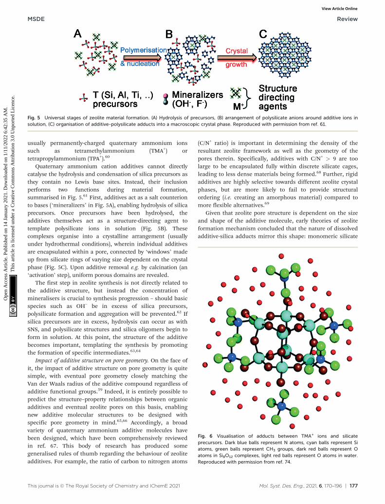
Quaternary ammonium cation additives cannot directlycatalyse the hydrolysis and condensation of silica precursors asthey contain no Lewis base sites. Instead, their inclusionperforms two functions during material formation,summarised in Fig. 5.61 First, additives act as a salt counterionto bases (‘mineralizers’ in Fig. 5A), enabling hydrolysis of silicaprecursors. Once precursors have been hydrolysed, theadditives themselves act as a structure-directing agent totemplate polysilicate ions in solution (Fig. 5B). Thesecomplexes organise into a crystalline arrangement (usuallyunder hydrothermal conditions), wherein individual additivesare encapsulated within a pore, connected by ‘windows’ madeup from silicate rings of varying size dependent on the crystalphase (Fig. 5C). Upon additive removal e.g. by calcination (an‘activation’ step), uniform porous domains are revealed.
The first step in zeolite synthesis is not directly related tothe additive structure, but instead the concentration ofmineralisers is crucial to synthesis progression – should basicspecies such as OH− be in excess of silica precursors,polysilicate formation and aggregation will be prevented.62 Ifsilica precursors are in excess, hydrolysis can occur as withSNS, and polysilicate structures and silica oligomers begin toform in solution. At this point, the structure of the additivebecomes important, templating the synthesis by promotingthe formation of specific intermediates.63,64
Impact of additive structure on pore geometry. On the face ofit, the impact of additive structure on pore geometry is quitesimple, with eventual pore geometry closely matching theVan der Waals radius of the additive compound regardless ofadditive functional groups.59 Indeed, it is entirely possible topredict the structure–property relationships between organicadditives and eventual zeolite pores on this basis, enablingnew additive molecular structures to be designed withspecific pore geometry in mind.65,66 Accordingly, a broadvariety of quaternary ammonium additive molecules havebeen designed, which have been comprehensively reviewedin ref. 67. This body of research has produced somegeneralised rules of thumb regarding the behaviour of zeoliteadditives. For example, the ratio of carbon to nitrogen atoms
(C/N+ ratio) is important in determining the density of theresultant zeolite framework as well as the geometry of thepores therein. Specifically, additives with C/N+ > 9 are toolarge to be encapsulated fully within discrete silicate cages,leading to less dense materials being formed.68 Further, rigidadditives are highly selective towards different zeolite crystalphases, but are more likely to fail to provide structuralordering (i.e. creating an amorphous material) compared tomore flexible alternatives.69
Given that zeolite pore structure is dependent on the sizeand shape of the additive molecule, early theories of zeoliteformation mechanism concluded that the nature of dissolvedadditive-silica adducts mirror this shape: monomeric silicate
Fig. 5 Universal stages of zeolite material formation. (A) Hydrolysis of precursors, (B) arrangement of polysilicate anions around additive ions insolution, (C) organisation of additive-polysilicate adducts into a macroscopic crystal phase. Reproduced with permission from ref. 61.
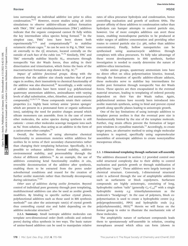
Fig. 6 Visualisation of adducts between TMA+ ions and silicateprecursors. Dark blue balls represent N atoms, cyan balls represent Siatoms, green balls represent CH3 groups, dark red balls represent Oatoms in Si8O12 complexes, light red balls represent O atoms in water.Reproduced with permission from ref. 74.
ions surrounding an individual additive ion prior to silicacondensation.70,71 However, recent studies using ab initiosimulations to observe additive-silicate adduct formationwith TMA+, TPA+ and tetrabutylammonium (TBA+) additivesindicate that the organic compound cannot fit fully withinthe key intermediate silica species being formed.72 In thesimplest case, TMA+ ions have been shown bothexperimentally73,74 and computationally75 to stabiliseoctameric silicate cages.75 As can be seen in Fig. 6, TMA+ ionssit externally to the Q3
8 structure, located centrally on theoutside of each face of the cubic ion.75,76 Similarly, TPA+ andTBA+ externally stabilise bicyclic Si11 structures throughnonspecific Van der Waals forces, thus aiding in theirdimerization and trimerization, which forms the basis of themacrostructure formation step shown in Fig. 5C.23
Impact of additive functional groups. Along with thediscovery that the additive size closely matches that of porecages in zeolites, their insensitivity to chemical functionality ofthe additive was also discovered.59 Accordingly, a wide varietyof additive molecules have been tested (e.g. polyfunctionalquaternary ammonium additives, aminoalkanes with varyinglevels of alkyl substitution, ether, thioether, and azamacrocyclecompounds).12,59,77,78 These compounds retain their cationicproperties (i.e. highly basic tertiary amine ‘proton sponges’which are present in a protonated form or organic sulfoniumions), satisfying the need for positive charges around whichsilicate monomers can assemble. Even in the case of crownether molecules, the active species during synthesis is stillcationic – crown ether molecules scavenge inorganic ions suchas Na+ from solution, thus acting as an additive in the form ofa cation-crown ether complex.79
Overall, the benefits of using alternative chemicalfunctionality to ammonium moieties within additives forzeolites lie in terms of their secondary characteristics ratherthan changing their templating behaviour. Specifically, it ispossible to enhance additive thermal stability, additiveenvironmental stability, and processability through thechoice of different additives.78 As an example, the use ofadditives containing ketal functionality enables in situ,reversible deconstruction of the additive after synthesis,enabling them to be extracted from the pores undersolvothermal conditions and reused for the creation offurther zeolite materials rather than thermally decomposingduring calcination.77,80
Other uses of additives during zeolite formation. Beyondcontrol of individual pore geometry through pore templating,multifunctional additives can also be used as zeolite growthmodifiers. By binding to specific surface crystal planes,polyfunctional additives such as those used in BIS synthesismethods81 can alter the anisotropic rate(s) of crystal growththus controlling crystal size and habit depending on theadditive molecular structure.82
2.2.3. Summary. Small isotropic additive molecules cantemplate zero-dimensional order (both colloids and orderedpores) during silica synthesis in two ways. The basic natureof amine-based additives can be used to manipulate relative
rates of silica precursor hydrolysis and condensation, hencecontrolling nucleation and growth of uniform SNSs. Thegreater affinity of these additives to condensation rather thanhydrolysis can hamper attempts to control particle size,however. Use of more complex additives can avert theseissues, enabling monodisperse particles to be produced atwider ranges of additive concentration and providing otherroutes to control particle size (i.e. pH, rather than additiveconcentration). Finally, hollow nanoparticles can besynthesised using azamacrocycle additives throughcomplexes with silica precursors. To fully take advantage ofthese recent developments in SNS synthesis, furtherinvestigation is needed to exactly determine the nature ofadditive-silica interactions.
Unlike amino groups, quaternary ammonium ions haveno direct effect on silica polymerisation kinetics. Instead,through the formation of specific additive-silicate adducts,these molecules serve to stabilise key intermediates forzeolite pore formation through nonspecific Van der Waalsforces. These species are then encapsulated in the eventualmaterial structure, leading to templating of ordered porositydependent on their Van der Waals radius. Again,polyfunctional amines have recently been introduced intozeolite materials synthesis, acting to bind and prevent crystalgrowth along specific planes leading to anisotropic growth.
One of the key limitations of using isotropic additives totemplate porous zeolites is that the eventual pore size isfundamentally limited by the size of the template molecule.Further, ring strain effects prevent the formation of largerpore windows in crystalline materials.11 Accordingly, to createlarger pores, an alternative method to using single moleculartemplates is required, specifically using supramolecularassemblies of anisotropic additives to create noncrystallinemesoporous silicas.
2.3. 1-Dimensional templating through surfactant self-assembly
The additives discussed in section 2.2 provided control oversolid structural complexity due to their ability to controlnucleation and particle growth or through stabilisation ofpolysilicate “cages”. These additives were largely isotropic inchemical structure. Conversely, 1-dimensional structuralorder is achieved through the use of amphiphilic additivessuch as surfactants or block copolymers. Surfactantcompounds are highly anisotropic, consisting of long,hydrophobic carbon “tails” (generally C8–C18)
83 with a singlehydrophilic moiety e.g. trimethylammonium as themolecule's “headgroup”. In the case of polymers, block co-polymerisation is used to create a hydrophobic centre (e.g.poly(propyleneoxide), PPO) and hydrophilic ends (e.g.poly(ethyleneoxide), PEO).84 Herein we will focus on theformer group in order to illustrate the mechanistic role ofthese molecules.
The amphiphilic nature of surfactant compounds leadsthem to spontaneously self-assemble in solution, creatingmesophases around which silica can form (shown in
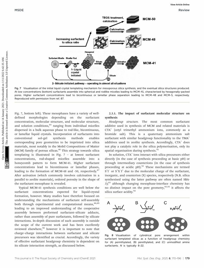
Fig. 7, bottom left). These mesophases have a variety of well-defined morphologies depending on the surfactantconcentration, molecular structure, and molecular structure,and solution conditions,85 ranging from individual micellesdispersed in a bulk aqueous phase to rod-like, bicontinuous,or lamellar liquid crystals. Incorporation of surfactants intoconventional sol–gel synthesis methods enablescorresponding pore geometries to be imprinted into silicamaterials, most notably in the Mobil Compositions of Matter(MCM) family of porous silicas.86 This strategy towards silicatemplating is illustrated in Fig. 7 – at lowest surfactantconcentrations, rod-shaped micelles assemble into ahoneycomb pattern to form MCM-41. Higher surfactantconcentrations lead to bicontinuous or lamellar phases,leading to the formation of MCM-48 and -50, respectively.87
After activation (which commonly involves calcination in aparallel to zeolite materials), ordered porosity in the shape ofthe surfactant mesophase is revealed.
Typical MCM-41 synthesis conditions are well below thesurfactant concentrations expected for liquid-crystalformation, however. Many studies have therefore focused onunderstanding the mechanisms of surfactant self-assemblyboth through experimental and computational means,88,89
leading to an improved understanding of the cooperativeassembly between preformed surfactant–silicate adducts,rather than assembly of pure surfactants, followed by silicateinteractions. In-depth discussion of such assembly is outsidethe scope of the current work and has been excellentlyreviewed elsewhere,90 however it is important to note thatcharge–charge interactions between surfactant and silicateprecursors was identified as crucial. Accordingly, the varietyof effective surfactant headgroup chemistry is dependent onits silicate interaction strength, as discussed below.
2.3.1. The impact of surfactant molecular structure onsynthesis
Headgroup structure. The most common surfactantadditive used in synthesis of MCM and related materials isCTA+ (cetyl trimethyl ammonium ions, commonly as abromide salt). This is a quaternary ammonium saltsurfactant with similar headgroup functionality to the TMA+
additives used in zeolite synthesis. Accordingly, CTA+ doesnot play a catalytic role in the silica polymerisation, only itsspatial organisation during synthesis.91
In solution, CTA+ ions interact with silica precursors eitherdirectly (in the case of synthesis proceeding at basic pH) orthrough intermediary counterions (in the case of synthesisproceeding at acidic pH).92 These mechanisms are termedS+I− or S+X−I+ due to the molecular charge of the surfactant,inorganic, and counterion (X) species, respectively (N.B. silicasynthesised using the latter pathway are often named SBA-3);83 although changing mesophase-interface chemistry hasno distinct impact on the pore geometry,83,93 it affects thesilica surface acidity.92
Fig. 7 Visualisation of the initial liquid crystal templating mechanism for mesoporous silica synthesis, and the eventual silica structures produced.At low concentrations (bottom) surfactants assemble into spherical and rodlike micelles leading to MCM-41, characterised by hexagonally-packedpores. Higher surfactant concentrations lead to bicontinuous or lamellar phase separation leading to MCM-48 and MCM-5, respectively.Reproduced with permission from ref. 87.
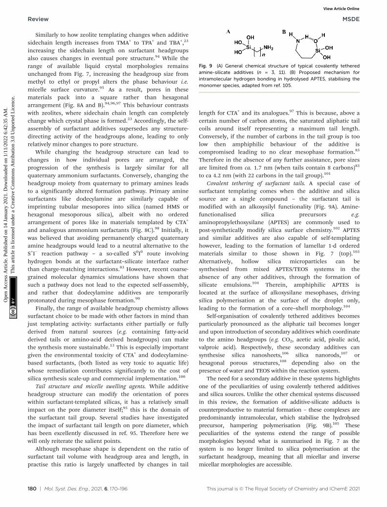
Fig. 8 Visualisation of cylindrical pore arrangement withinsurfactant templated silicas as a function of headgroup chemistryfor (A) permthylated, (B) perethylated, and (C) unmodified aminesurfactants. N is typically 8–22.
Similarly to how zeolite templating changes when additivesidechain length increases from TMA+ to TPA+ and TBA+,23
increasing the sidechain length on surfactant headgroupsalso causes changes in eventual pore structure.94 While therange of available liquid crystal morphologies remainsunchanged from Fig. 7, increasing the headgroup size frommethyl to ethyl or propyl alters the phase behaviour i.e.micelle surface curvature.95 As a result, pores in thesematerials pack into a square rather than hexagonalarrangement (Fig. 8A and B).94,96,97 This behaviour contrastswith zeolites, where sidechain chain length can completelychange which crystal phase is formed.23 Accordingly, the self-assembly of surfactant additives supersedes any structure-directing activity of the headgroups alone, leading to onlyrelatively minor changes to pore structure.
While changing the headgroup structure can lead tochanges in how individual pores are arranged, theprogression of the synthesis is largely similar for allquaternary ammonium surfactants. Conversely, changing theheadgroup moiety from quaternary to primary amines leadsto a significantly altered formation pathway. Primary aminesurfactants like dodecylamine are similarly capable ofimprinting tubular mesopores into silica (named HMS orhexagonal mesoporous silica), albeit with no orderedarrangement of pores like in materials templated by CTA+
and analogous ammonium surfactants (Fig. 8C).98 Initially, itwas believed that avoiding permanently charged quaternaryamine headgroups would lead to a neutral alternative to theS+I− reaction pathway – a so-called S0I0 route involvinghydrogen bonds at the surfactant–silicate interface ratherthan charge-matching interactions.83 However, recent coarse-grained molecular dynamics simulations have shown thatsuch a pathway does not lead to the expected self-assembly,and rather that dodecylamine additives are temporarilyprotonated during mesophase formation.99
Finally, the range of available headgroup chemistry allowssurfactant choice to be made with other factors in mind thanjust templating activity: surfactants either partially or fullyderived from natural sources (e.g. containing fatty-acidderived tails or amino-acid derived headgroups) can makethe synthesis more sustainable.13 This is especially importantgiven the environmental toxicity of CTA+ and dodecylamine-based surfactants, (both listed as very toxic to aquatic life)whose remediation contributes significantly to the cost ofsilica synthesis scale-up and commercial implementation.100
Tail structure and micelle swelling agents. While additiveheadgroup structure can modify the orientation of poreswithin surfactant-templated silicas, it has a relatively smallimpact on the pore diameter itself;95 this is the domain ofthe surfactant tail group. Several studies have investigatedthe impact of surfactant tail length on pore diameter, whichhas been excellently discussed in ref. 95. Therefore here wewill only reiterate the salient points.
Although mesophase shape is dependent on the ratio ofsurfactant tail volume with headgroup area and length, inpractise this ratio is largely unaffected by changes in tail
length for CTA+ and its analogues.97 This is because, above acertain number of carbon atoms, the saturated aliphatic tailcoils around itself representing a maximum tail length.Conversely, if the number of carbons in the tail group is toolow then amphiphilic behaviour of the additive iscompromised leading to no clear mesophase formation.83
Therefore in the absence of any further assistance, pore sizesare limited from ca. 1.7 nm (when tails contain 8 carbons)83
to ca 4.2 nm (with 22 carbons in the tail group).101
Covalent tethering of surfactant tails. A special case ofsurfactant templating comes when the additive and silicasource are a single compound – the surfactant tail ismodified with an alkoxysilyl functionality (Fig. 9A). Amine-functionalised silica precursors e.g.aminopropylethoxysilane (APTES) are commonly used topost-synthetically modify silica surface chemistry.102 APTESand similar additives are also capable of self-templatinghowever, leading to the formation of lamellar 1-d orderedmaterials similar to those shown in Fig. 7 (top).103
Alternatively, hollow silica microparticles can besynthesised from mixed APTES/TEOS systems in theabsence of any other additives, through the formation ofsilicate emulsions.104 Therein, amphiphilic APTES islocated at the surface of alkoxysilane mesophases, drivingsilica polymerisation at the surface of the droplet only,leading to the formation of a core–shell morphology.104
Self-organisation of covalently tethered additives becomesparticularly pronounced as the aliphatic tail becomes longerand upon introduction of secondary additives which coordinateto the amino headgroups (e.g. CO2, acetic acid, pivalic acid,valproic acid). Respectively, these secondary additives cansynthesise silica nanosheets,106 silica nanorods,107 orhexagonal porous structures,108 depending also on thepresence of water and TEOS within the reaction system.
The need for a secondary additive in these systems highlightsone of the peculiarities of using covalently tethered additivesand silica sources. Unlike the other chemical systems discussedin this review, the formation of additive-silicate adducts iscounterproductive to material formation – these complexes arepredominantly intramolecular, which stabilise the hydrolysedprecursor, hampering polymerisation (Fig. 9B).105 Thesepeculiarities of the systems extend the range of possiblemorphologies beyond what is summarised in Fig. 7 as thesystem is no longer limited to silica polymerisation at thesurfactant headgroup, meaning that all micellar and inversemicellar morphologies are accessible.
Fig. 9 (A) General chemical structure of typical covalently tetheredamine-silicate additives (n = 3, 11). (B) Proposed mechanism forintramolecular hydrogen bonding in hydrolysed APTES, stabilising themonomer species, adapted from ref. 105.
2.3.2. Comparison with additives in zeolitic materials.Whereas zeolite materials are crystalline, the larger pores insurfactant-templated silicas necessitate an amorphous structure toprevent unacceptable ring strain around the pore.11 This impactson the synthesis methods significantly – while hydrothermalsynthesis such as in zeolites is also possible in surfactant-templated mesoporous silicas, the majority of these materials aresynthesised using sol–gel conditions.86 Interestingly, this appearsto be related to the nature of the additive: PEO–PPO blockcopolymers require hydrothermal conditions in the same vein aszeolite materials,84 while amine- or ammonium-headedsurfactants require no such driving force.83
In terms of templating effects, templating usingsurfactants is dominated by their self-assembly rather thanthe nonspecific Van der Waals interactions present in zeolitetemplating, despite similarities between headgroup chemistryof surfactants and zeolite additives.70,74 Further, unlike thenonspecific Van der Waals interactions present in zeolitesynthesis, charge-matching interactions present betweensurfactant additives and silicate precursors are crucial to the1-dimensional templating in surfactant-silica systems.Although this means that zeolites are capable of forming agreater variety of specific crystal phases and structures,109
surfactant-templated silicas are capable of exhibiting abroader range of structural characteristics.
2.3.3. Summary. Use of self-assembling surfactant additivesduring silica synthesis enables templating of their organisedstructure into the materials. A vast body of research has beenconducted in this area, but it is important to note:
• Surfactants do not play a catalytic role in the hydrolysisor condensation of silica precursors.
• Formation of ordered pores depends on the ability to formstrong surfactant–silicate complexes by charge matching; theuse of non-permanently charged surfactants only producesordered pores when surfactants are in charged states.
• Dynamic complexation between silicates and thesurfactants changes the self-assembly behaviour ofsurfactants, reducing the overall micelle curvature andchanging the phase space of the self-assembly.
Despite the impressive number of different structurespossible to be synthesised by the incorporation of surfactantsinstead of isotropic templating additives, the structures they canadopt are limited by the self-assembly behaviour. Theselimitations can be extended by the use of additives covalentlytethered to the silica sources – enabling polymerisation at thetail group and freeing up the head group to interact withsecondary additives thus extending the range of possiblemorphologies. Self-assembly of dispersed phases in solution is amature science however, therefore it is evident that only a fewoverarching pore geometries will be possible. In order to surpassthis, further complexity in the additive structure is required.
2.4. 2-Dimensional structural ordering
We define 2-dimensional ordering as the simultaneous controlover two structural or morphological properties. Although
countless combinations of properties could be produced forspecific applications, their control is always reliant on theadditive chosen for their synthesis. To illustrate thiscorrelation, we summarise the three major families ofmaterials prepared with such structural specifications. Namely,hierarchically porous silicas, mesoporous silica nanoparticlesand silica morphologies beyond spheres. In all these cases, theapproach has been to combine previous methods to controlfeatures at different length-scales. This includes thesimultaneous use of small amines and surfactants orsurfactants and hard spheres to impart micro–meso or meso–macro porosities, respectively. While the activity of theseadditives has already been discussed, combining more thanone together without compromising the activity of eitherrequires some consideration.
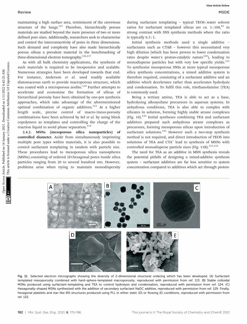
2.4.1. Hierarchical porosity. The need for silicas withdifferent pore size combinations is made evident by theirwidespread applications as catalyst supports. It is wellestablished that catalysis is a multiscale process, whereproperties from macro- to nanoscale determine theperformance of a material. This is particularly true for therole of pores inside a catalytic material. For example, thesmall pores of zeolites provide excellent selectivity butseverely limit mass transport.110 In order to address suchdrawbacks, significant efforts have been dedicated todeveloping hierarchical zeolites and mesoporous silicas, ashave been discussed in ref. 111 and 112 respectively. Forthese materials traditional syntheses described in sections2.2.2 and 2.3 are modified by inclusion of hard macroscopicobjects, commonly polystyrene latex spheres, around whichthe reactions proceed as previously described (Fig. 11A).113
Alternatively, hierarchical porosity can be included by usingadditives which combine the activity of both small molecularand liquid-crystal like templating. A key example of this is theblock copolymer PEO–PPO–PEO in hierarchically porous SBA-15.114 In this material, PPO cores of the polymer assemble intoliquid crystal phases similar to those described in section 2.3,creating mesoporous channels of 4–20 nm diameter.112 PEOgroups become encapsulated in pore walls upon condensationof silica around the PPO cores, leading to microporous‘bridges’ between channels, depending on the conditionsunder which the additive is removed.114 By bridging betweenpores, guest transport within the materials is improvedcompared to surfactant-templated silicas.
Hierarchical porosity is of particular importance for bulk-chemistry applications, where transport of fluids and surfacereactions need to be optimised. By combining large pores thatlead to smaller ones, the structure is accessible while
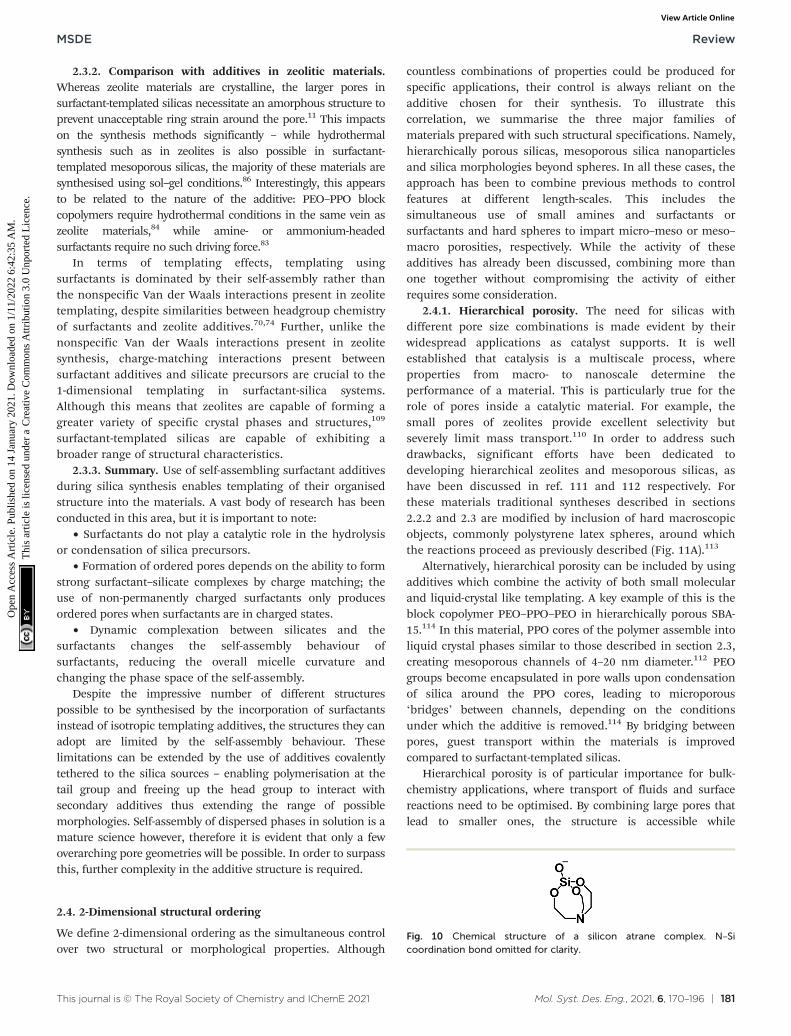
Fig. 10 Chemical structure of a silicon atrane complex. N–Sicoordination bond omitted for clarity.
maintaining a high surface area, reminiscent of the cavernousstructure of the lungs.115 Therefore, hierarchically porousmaterials are studied beyond the mere presence of two or moredefined pore sizes. Additionally, researchers seek to characteriseand control the interconnectivity of pores in three dimensions.Such demand and complexity have also made hierarchicallyporous silicas a prevalent material in the benchmarking ofthree-dimensional electron tomography.116,117
As with all bulk chemistry applications, the synthesis ofsuch materials is required to be inexpensive and scalable.Numerous strategies have been developed towards that end.For instance, Anderson et al. used readily availablediatomaceous earth to provide macroporous structure, whichwas coated with a microporous zeolite.118 Further attempts toaccelerate and economise the formation of silicas ofhierarchical porosity have been obtained by one-pot synthesisapproaches, which take advantage of the aforementionedoptimal combination of organic additives.115 At a higherlength scale, precise control of macro-/meso-porositycombinations have been achieved by Sel et al. by using blockcopolymers as templates and controlling the charge of thereaction liquid to avoid phase separation.119
2.4.2. MSNs (mesoporous silica nanoparticles) ofcontrolled diameter. Aside from simultaneously imprintingmultiple pore types within materials, it is also possible tocontrol surfactant templating in tandem with particle size.These procedures lead to mesoporous silica nanospheres(MSNs) consisting of ordered 2D-hexagonal pores inside silicaparticles ranging from 20 to several hundred nm. However,problems arise when trying to maintain monodispersity
during surfactant templating – typical TEOS :water solventratios for surfactant templated silicas are ca. 1 : 100,83 instrong contrast with SNS synthesis methods where the ratiois typically 6.5 : 1.
Initial synthesis methods used a single additive –
surfactants such as CTAB – however this necessitated veryhigh dilution (which has been proven to lower condensationrates despite water's proton-catalytic nature120), leading tomonodisperse particles but with very low specific yields.121
To synthesise mesoporous SNSs at more typical mesoporoussilica synthesis concentrations, a mixed additive system istherefore required, consisting of a surfactant additive and anadditive which decelerates rather than accelerates hydrolysisand condensation. To fulfil this role, triethanolamine (TEA)is commonly used.
Being a tertiary amine, TEA is able to act as a base,hydrolysing alkoxysilane precursors in aqueous systems. Inanhydrous conditions, TEA is also able to complex withsilicates in solution, forming highly stable atrane complexes(Fig. 10).122 Initial syntheses combining TEA and surfactantadditives prepared such anhydrous atrane complexes asprecursors, forming mesoporous silicas upon introduction ofsurfactant solutions.123 However such a two-step synthesismethod is not required, and direct introduction of TEOS intosolutions of TEA and CTA+ lead to synthesis of MSNs withcontrolled monodisperse particle sizes (Fig. 11B).121,124
The need for TEA as an additive in MSN synthesis revealsthe potential pitfalls of designing a mixed-additive synthesissystem – surfactant additives are far less sensitive to systemconcentration compared to additives which act through proton-
Fig. 11 Selected electron micrographs showing the diversity of 2-dimensional structural ordering which has been developed. (A) Surfactanttemplated mesoporosity combined with hard-sphere-templated macroporosity, reproduced with permission from ref. 113. (B) Stable colloidalMSNs produced using surfactant-templating and TEA to control hydrolysis and condensation, reproduced with permission from ref. 124. (C)Hexagonally-shaped MSNs synthesised with the addition of secondary surfactant NaDC additive, reproduced with permission from ref. 129. Finally,hexagonal platelets and star-like BIS structures produced using PLL in either static (D) or flowing (E) conditions, reproduced with permission fromref. 132.
transfer catalysis. The flexibility of silica synthesis mechanismsis also highlighted however – using TEA as an inhibitor to TEOShydrolysis rather than a catalyst restored the SNS synthesismechanism to an otherwise incompatible reaction composition.Therefore, through thorough understanding of the reactionmechanisms present and the additive's role therein, it is clearlypossible to design much more complex silica materials thanotherwise would be available.
2.4.3. Morphologies beyond spheres. So far, we have seen2-dimentionsal particle control through pore templating ontwo length scales and simultaneous pore and particle sizecontrol. The final 2-dimensional structural ordering is tocontrol morphology in two dimensions i.e. synthesis ofcontrolled SNS with nonspherical morphologies.
As a first example, SBA-15 materials templated by PEO–PPO–PEO block copolymers can be arranged into hexagonalmorphologies through control over liquid crystal formationduring synthesis. As previously shown in Fig. 7, initial stagesof mesoporous silica formation involves co-condensation ofsilicate ions around surfactant micelles. In the case ofpolymeric additives, the size of these polymer–silicatecomplexes is discrete since silica condenses around a singleadditive (unlike surfactant–silica micelles whose self-assembling behaviour changes during co-condensation90).Importantly, these polymer–silicate complexes can behave ascolloids in their own right, with association behaviouraffected by temperature and ionic strength.125,126 Therefore,by careful control of temperature and solution ionicconditions during early stages of the reaction, orderedassociation of polymer–silicate micelles into liquid-crystalphases is possible, leading to hexagonal ‘monocrystalline’particles with controllable aspect ratio.127,128
This ‘colloidal phase separation mechanism’ can beapplied to surfactant templated MSNs using secondaryadditives. Specifically, the use of binary surfactant mixtures,such as CTAB and sodium deoxycholate (NaDC), has provensuccessful in producing a variety of MSN shapes (Fig. 11C).129
By varying the ratios of organic additives in the catanionicmixture, reproducible tuning of nanoshapes has beenreported. Such studies have been able to predictably producehexagonal plates, toroidal particles and nanorods.130
In contrast, morphology control is achieved in bioinspiredsyntheses using chiral polymers such as poly-L-lysine.131
Through the self-assembly of α-helixes during synthesis,flake-like hexagonal silicas can be synthesised (Fig. 11D).Interestingly, morphology can be altered by performing thesynthesis under flow (Fig. 11E).132
Finally, macroporous silica microspheres can beintroduced by combining covalently-tethered additives withstrong surfactant character with TEOS: in the case of APTESadditives, reactions with TEOS and water led to the formationof hollow microbeads.104 When the length of the aliphatictail is extended from 3 carbons to 11 and well mixed, it formsa double-emulsion system with TEOS and water, leading tothe formation of macroporous particles.133 Although controlover both particle size and macropore diameter have yet to
be demonstrated, this interesting new approach showssignificant promise for creating a wide variety of2-dimensional templating behaviour.
2.4.4. Summary. On the face of it, 2-dimensional structuralordering is the simultaneous and independent combinationof the phenomena described in section 2. While this may bethe case on some occasions e.g. the formation of hard-spheretemplated zeolites and mesoporous silicas, in the case ofMSNs or nonspherical mesoporous nanoparticles, significantcare must be taken to compensate for interactions betweenthe additives in the system. In addition, although formationmechanisms have been proposed for the majority ofmaterials discussed in this section, further research isrequired to gain a systematic understanding of theirparameter space and extend capabilities to 3-dimensionalstructural ordering.
2.5. 3-Dimensional structural ordering
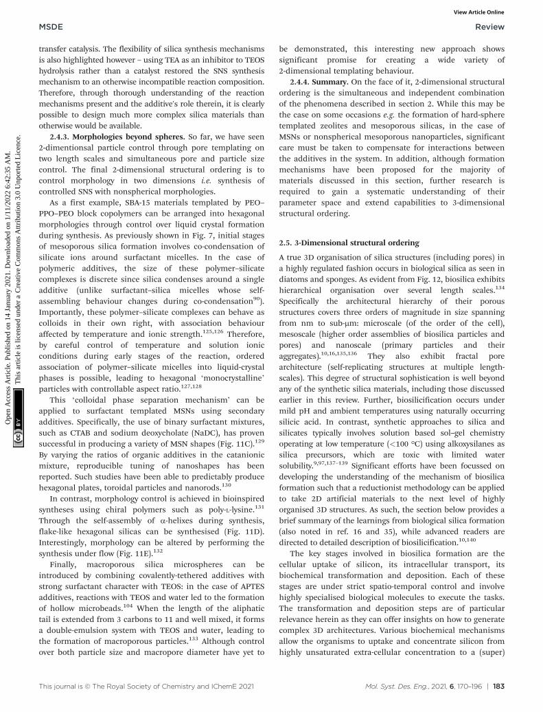
A true 3D organisation of silica structures (including pores) ina highly regulated fashion occurs in biological silica as seen indiatoms and sponges. As evident from Fig. 12, biosilica exhibitshierarchical organisation over several length scales.134
Specifically the architectural hierarchy of their porousstructures covers three orders of magnitude in size spanningfrom nm to sub-μm: microscale (of the order of the cell),mesoscale (higher order assemblies of biosilica particles andpores) and nanoscale (primary particles and theiraggregates).10,16,135,136 They also exhibit fractal porearchitecture (self-replicating structures at multiple length-scales). This degree of structural sophistication is well beyondany of the synthetic silica materials, including those discussedearlier in this review. Further, biosilicification occurs undermild pH and ambient temperatures using naturally occurringsilicic acid. In contrast, synthetic approaches to silica andsilicates typically involves solution based sol–gel chemistryoperating at low temperature (<100 °C) using alkoxysilanes assilica precursors, which are toxic with limited watersolubility.9,97,137–139 Significant efforts have been focussed ondeveloping the understanding of the mechanism of biosilicaformation such that a reductionist methodology can be appliedto take 2D artificial materials to the next level of highlyorganised 3D structures. As such, the section below provides abrief summary of the learnings from biological silica formation(also noted in ref. 16 and 35), while advanced readers aredirected to detailed description of biosilicification.10,140
The key stages involved in biosilica formation are thecellular uptake of silicon, its intracellular transport, itsbiochemical transformation and deposition. Each of thesestages are under strict spatio-temporal control and involvehighly specialised biological molecules to execute the tasks.The transformation and deposition steps are of particularrelevance herein as they can offer insights on how to generatecomplex 3D architectures. Various biochemical mechanismsallow the organisms to uptake and concentrate silicon fromhighly unsaturated extra-cellular concentration to a (super)
saturated, yet stable intra-cellular concentration. This allowsthe organism to regulate the precursor chemistry and supply,which in turn provides spatio-temporal control over silicaformation and deposition.
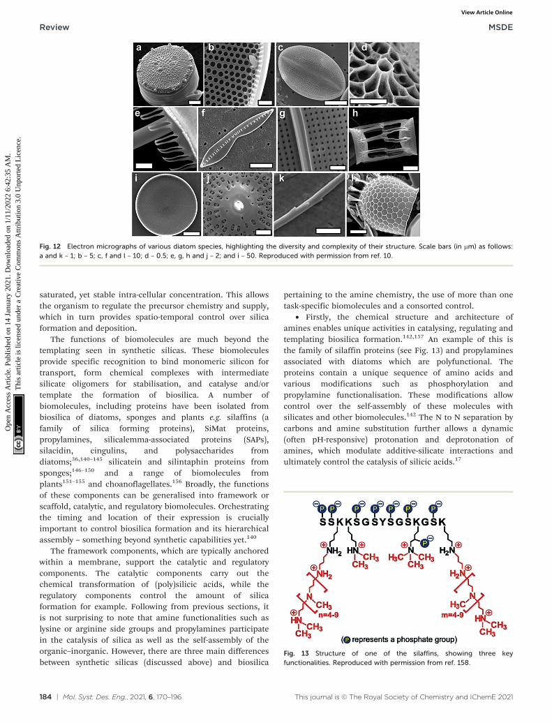
The functions of biomolecules are much beyond thetemplating seen in synthetic silicas. These biomoleculesprovide specific recognition to bind monomeric silicon fortransport, form chemical complexes with intermediatesilicate oligomers for stabilisation, and catalyse and/ortemplate the formation of biosilica. A number ofbiomolecules, including proteins have been isolated frombiosilica of diatoms, sponges and plants e.g. silaffins (afamily of silica forming proteins), SiMat proteins,propylamines, silicalemma-associated proteins (SAPs),silacidin, cingulins, and polysaccharides fromdiatoms;36,140–145 silicatein and silintaphin proteins fromsponges;146–150 and a range of biomolecules fromplants151–155 and choanoflagellates.156 Broadly, the functionsof these components can be generalised into framework orscaffold, catalytic, and regulatory biomolecules. Orchestratingthe timing and location of their expression is cruciallyimportant to control biosilica formation and its hierarchicalassembly – something beyond synthetic capabilities yet.140
The framework components, which are typically anchoredwithin a membrane, support the catalytic and regulatorycomponents. The catalytic components carry out thechemical transformation of (poly)silicic acids, while theregulatory components control the amount of silicaformation for example. Following from previous sections, itis not surprising to note that amine functionalities such aslysine or arginine side groups and propylamines participatein the catalysis of silica as well as the self-assembly of theorganic–inorganic. However, there are three main differencesbetween synthetic silicas (discussed above) and biosilica
pertaining to the amine chemistry, the use of more than onetask-specific biomolecules and a consorted control.
• Firstly, the chemical structure and architecture ofamines enables unique activities in catalysing, regulating andtemplating biosilica formation.142,157 An example of this isthe family of silaffin proteins (see Fig. 13) and propylaminesassociated with diatoms which are polyfunctional. Theproteins contain a unique sequence of amino acids andvarious modifications such as phosphorylation andpropylamine functionalisation. These modifications allowcontrol over the self-assembly of these molecules withsilicates and other biomolecules.142 The N to N separation bycarbons and amine substitution further allows a dynamic(often pH-responsive) protonation and deprotonation ofamines, which modulate additive-silicate interactions andultimately control the catalysis of silicic acids.17
Fig. 12 Electron micrographs of various diatom species, highlighting the diversity and complexity of their structure. Scale bars (in μm) as follows:a and k – 1; b – 5; c, f and l – 10; d – 0.5; e, g, h and j – 2; and i – 50. Reproduced with permission from ref. 10.
Fig. 13 Structure of one of the silaffins, showing three keyfunctionalities. Reproduced with permission from ref. 158.
• Secondly, the presence of more than one biomoleculewith specific tasks (self-assembly or regulation). This is verydifferent to the typical in vitro synthesis where one or at themost two additives are used.
• Thirdly, the special control exerted by the frameworkcomponents as well as other dynamic processes that canmove these freshly formed biosilica particles to the desiredsites. This level of very complex temporal and spatial controlover each step, makes biosilica remarkably distinct.
To demonstrate how these effects combine to form suchcomplex architectures, we present the case study of the silicafrustule in Thalassiosira pseudonana (Fig. 12A) where theoverall structure takes the shape of a nonporous cylinder‘girdle’ capped with ‘valves’ of highly ordered hierarchicalporosity.159,160 On the largest scales, the separate structure offrustule walls and valves is a result of reaction localisationwithin the cell – valves are deposited within a specialisedsilica deposition vesicle (SDV) whose overall shape matchesthat of the valve structure. Valves are then exocytosed fromthe diatom, whereupon segments of the girdle begin to formand attach themselves to the extracellular silica structure.145
While the SDV provides a template for the overall structure ofthe valve, its ordered pore network is formed throughcomplex, synergistic self-assembly of silaffins and otherpolyamine biomolecules.161 The exact mechanism of thehierarchical pore formation within the SDV is a matter ofongoing research,162 however is it clear that synergistic self-assembly between multiple biomolecules within a confinedspace is key for the formation of 3-dimensionally orderedfrustule valves.
3. A combined perspective onadditive function
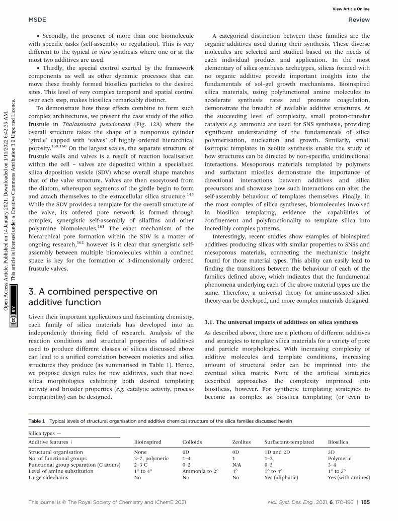
Given their important applications and fascinating chemistry,each family of silica materials has developed into anindependently thriving field of research. Analysis of thereaction conditions and structural properties of additivesused to produce different classes of silicas discussed abovecan lead to a unified correlation between moieties and silicastructures they produce (as summarised in Table 1). Hence,we propose design rules for new additives, such that novelsilica morphologies exhibiting both desired templatingactivity and broader properties (e.g. catalytic activity, processcompatibility) can be designed.
A categorical distinction between these families are theorganic additives used during their synthesis. These diversemolecules are selected and studied based on the needs ofeach individual product and application. In the mostelementary of silica-synthesis archetypes, silicas formed withno organic additive provide important insights into thefundamentals of sol–gel growth mechanisms. Bioinspiredsilica materials, using polyfunctional amine molecules toaccelerate synthesis rates and promote coagulation,demonstrate the breadth of available additive structures. Atthe succeeding level of complexity, small proton-transfercatalysts e.g. ammonia are used for SNS synthesis, providingsignificant understanding of the fundamentals of silicapolymerisation, nucleation and growth. Similarly, smallisotropic templates in zeolite synthesis enable the study ofhow structures can be directed by non-specific, unidirectionalinteractions. Mesoporous materials templated by polymersand surfactant micelles demonstrate the importance ofdirectional interactions between additives and silicaprecursors and showcase how such interactions can alter theself-assembly behaviour of templates themselves. Finally, inthe most complex of silica syntheses, biomolecules involvedin biosilica templating, evidence the capabilities ofconfinement and polyfunctionality to template silica intoincredibly complex patterns.
Interestingly, recent studies show examples of bioinspiredadditives producing silicas with similar properties to SNSs andmesoporous materials, connecting the mechanistic insightfound for those material types. This ability can easily lead tofinding the transitions between the behaviour of each of thefamilies defined above, which indicates that the fundamentalphenomena underlying each of the above material types are thesame. Therefore, a universal theory for amine-assisted silicatheory can be developed, and more complex materials designed.
3.1. The universal impacts of additives on silica synthesis
As described above, there are a plethora of different additivesand strategies to template silica materials for a variety of poreand particle morphologies. With increasing complexity ofadditive molecules and template conditions, increasingamount of structural order can be imprinted into theeventual silica matrix. None of the artificial strategiesdescribed approaches the complexity imprinted intobiosilicas, however. For synthetic templating strategies tobecome as complex as biosilica templating (or even to
Table 1 Typical levels of structural organisation and additive chemical structure of the silica families discussed herein
Silica types →
Bioinspired Colloids Zeolites Surfactant-templated BiosilicaAdditive features ↓
Structural organisation None 0D 0D 1D and 2D 3DNo. of functional groups 2–7, polymeric 1–4 1 1–2 PolymericFunctional group separation (C atoms) 2–3 C 0–2 N/A 0–3 3–4Level of amine substitution 1° to 4° Ammonia to 2° 4° 1° to 4° 1° to 3°Large sidechains No No No Yes (aliphatic) Yes (with amines)
understand their formation mechanisms better), a moreholistic view of template structure–function relationships isrequired. The first step towards this lies in analysing whatsimilarities are present between the different templatingstrategies described before and hence how directlycomparable different synthesis methods are.
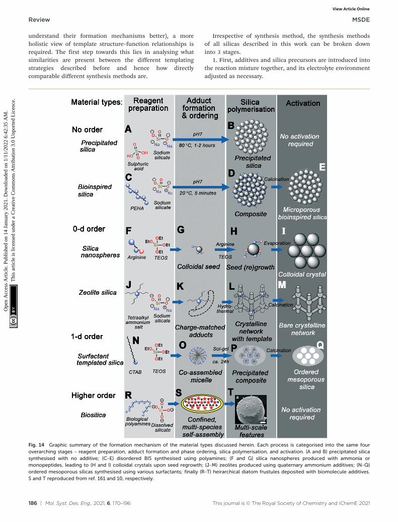
Irrespective of synthesis method, the synthesis methodsof all silicas described in this work can be broken downinto 3 stages.
1. First, additives and silica precursors are introduced intothe reaction mixture together, and its electrolyte environmentadjusted as necessary.
Fig. 14 Graphic summary of the formation mechanism of the material types discussed herein. Each process is categorised into the same fouroverarching stages – reagent preparation, adduct formation and phase ordering, silica polymerisation, and activation. (A and B) precipitated silicasynthesised with no additive; (C–E) disordered BIS synthesised using polyamines; (F and G) silica nanospheres produced with ammonia ormonopeptides, leading to (H and I) colloidal crystals upon seed regrowth; (J–M) zeolites produced using quaternary ammonium additives; (N–Q)ordered mesoporous silicas synthesised using various surfactants; finally (R–T) heirarchical diatom frustules deposited with biomolecule additives.S and T reproduced from ref. 161 and 10, respectively.
2. Second, additives and small silica species (Si1–11)interact, forming additive-silicate complexes which form thebasis of templating.
3. Silica species within these complexes then condense(either spontaneously or under some external driving forces),forming structured silica materials.
4. Finally, almost ubiquitously for artificial silica materials,the additive is then removed by an ‘activation’ process.
Fig. 14 graphically demonstrates the similarities betweendifferent silica synthesis strategies. Industrial precipitatedsilica is produced using no structural direction, only silicasalts and acids to neutralise them (Fig. 14A). This leads tosilica with a range of possible pore sizes depending on howthe sol–gel reactions progress, requiring no activation of thepore structure before eventual use (Fig. 14B). Incorporationof polyamine additives to the system at high concentrationleads to acceleration of this process (Fig. 14C), howeverwithout any clear ordering at circum-neutral pH (where therate of condensation is maximised, Fig. 14D).
Smaller protonatable additives like ammonia, amino acids,or azamacrocycles leads to controlled nucleation and growth ofstable colloidal nanoparticles, depending on a careful balanceof TEOS hydrolysis and condensation rates (Fig. 14F). Oncehomogeneous nucleation has occurred, a monodispersesuspension of stable colloidal silicas can be grown by particleregrowth (Fig. 14G), or ordered crystals seeded from the parentsol by solvent evaporation (Fig. 14H–I).
Substitution of protonatable amine additives with per-substituted ammonium salt additives leads to synthesis ofzeolite materials rather than colloidal silicas (Fig. 14J). Ratherthan controlling the rate of precursor hydrolysis, charge-matched adducts between additives and silicate species form,templating the eventual zeolite pore structure dependent onadditive chemical structure (Fig. 14K). Aggregation andordering of additives–silicate complexes (e.g. underhydrothermal conditions) leads to the formation ofcrystalline networks with additive-shaped pores (Fig. 14L).These pores are finally revealed through calcination or otheractivation procedures (Fig. 14M).
Incorporation of amphiphilic moieties e.g. hydrophobic tailsinto additives permits simultaneous additive self-assembly andadditive-silicate adduct formation, imprinting larger porespaces due to liquid-crystal-like additive co-assembly with silicaprecursors (Fig. 14N–O). Although a range of surfactantheadgroup chemistry is possible, these co-assembled adductsappear to act similarly to those in Fig. 14K – requiring charge-matching interactions for ordered mesophase formation. Sol–gel precipitation of these structures leads to a nonporouscomposite containing well-ordered organic domains, and againcalcination of the organic additive reveals an ordered porenetwork (Fig. 14P–Q).
Higher-order templating involves the use of mixedadditive species as well as other driving forces such ascontrolled flow or additive confinement (Fig. 14R). Forexample, in the case of biosilica templating in the diatom T.pseudonana, a mixture of silaffin proteins and long-chain
polyamines are postulated to self-assemble inside a silica-deposition vesicle (Fig. 14S).160,161 Polymerisation around thismesophase then occurs, leading to formation of highlypatterned silica on a number of length scales (Fig. 14T).
We propose that the mechanistic driving forces shown inFig. 14 are identical; that is to say specific reactionintermediates identified in section 2 form due to the samefundamental additive-silicate interactions and thatdifferences in the eventual silica structure arise primarily dueto variations in the additive molecular structure. As aconsequence of our hypothesis, insights from any additive-silica system will be able to provide insight into any other. Inthe following sections, we justify this hypothesis byhighlighting examples of additive-silica systems exhibitingbehaviour typically found in other material “families” (asdefined in Fig. 1), particularly bioinspired silica (BIS)materials (the system where the most diversity of additivestructure has been explored).16 Although within this work BISmaterials are classified as providing no structural direction,examples of ‘bioinspired’ techniques and additives can befound throughout: be it the use of peptides51,52,163 andazamacrocycles54–56 to synthesise monodisperse silicananospheres and colloidal crystals; bio-derived surfactantsproviding 1d structural direction;13 or flow-inducedarrangement of polypeptides into plates.132
From the mechanisms summarised in Fig. 14, 4 keydriving forces can be identified:
• Control over relative rates of silica hydrolysis andcondensation (hence nucleation).
• Charge-matching silicate-additive adduct formation.• Self-assembly into liquid-crystal-like mesophases.• Reaction centre localisation through flow or confinement.Structural complexity is imprinted into materials when
one or more of the above features is present in additivemolecules present within the reaction system. Whenmultiple driving forces are present (e.g. in the cases ofsurfactant additives which charge-match with silicates), ormultiple additive species are present, greater structuralinformation can be imprinted. By identifying the 4 keydriving forces to ordering regardless of the silica systemused, specific moieties connected to each driving force canbe identified and hence design rules for systematicallyintroducing more complexity into porous silicas can bemade.
3.2. Additive activity – from molecules to moieties
What aspects of each molecule lead to activity or templating?Activity is clearly based around the amine and cationicammonium moieties, but as can be seen from biosilicas thelocation of these functional groups on the molecule has afurther impact on activity. There have been several studieslinking additive molecular structure with activity,17,18,20,21
from which we can infer design rules for future additives.At initial stages of reactions, amine moieties play an
important role in facilitating hydrolysis (if present) and
condensation of silica precursors. From fundamentalcomputational and NMR-based studies of very early stages ofsynthesis, a strong correlation between conjugate baseconcentration and both hydrolysis and condensation rate hasbeen identified.19 Accordingly, lowering the pKa of amineadditives can lead to acceleration of silica synthesis (albeit tothe detriment of ordered structural direction17). Initial stages ofsilica condensation proceed with third-order kinetics withrespect to [Si], indicating the formation of trimeric silica speciesfrom Si1–2 species.41,164,165 On this basis, kinetic investigationsinto the effect of additive structure on silicate condensation ratehave confirmed the positive correlation between conjugate basebehaviour and silicate trimerization rates.17
In terms of additive structure, hydrolysis is thereforeaccelerated through alkylation of amine molecules,17,21,22
additive homologation (i.e. introduction of a larger numberof amine moieties),18,41,166 and separation of aminemoieties.17,20 Further, reduction of pKa by e.g. using pyridyladditives19 or substituting with electron-donating groups(benzyl or allyl)21 further accelerate silica condensation. Wenote that even slight structural changes can lead to dramaticincreases in catalysis rates – increasing amine separationfrom 2 bridging carbon atoms to 3, or adding a single methylgroup per amine, can lead to large increases in catalysisrates.17 Although few studies have studied the catalyticbehaviour of quaternary ammonium additives, it appears thatthese moieties are even more effective than free-base aminemoieties despite the fact that they cannot participate inproton transfer catalysis.21,22 It has been postulated thatquaternary ammonium ions instead work by creating areas ofhigher local [Si] concentration through macroscopic charge-matching effects (coacervation).166
In terms of pore templating, amine moiety separation ofmore than 6 carbon atoms introduces hydrophobic characterinto the molecule to induce phase separation behavioursimilar to that seen in surfactant additives. This leads toincreased pore sizes when used to synthesise BIS, but at theexpense of comparatively reduced overall synthesis rates dueto the lack of proximate polyfunctionality.135 Increasinghydrophobicity of the templates, by either high homologationor methylation have also shown a tendency to form hollowsilica particles. This is due to mesophase formation creatinglarge microdroplets of the additive in solution around whichsilica shells form, in a parallel to both surfactant-templatedand biomineralized silicas.17
Charge-matching-based aggregation between positivelycharged additives and larger colloidal silica is also importantbeyond the molecular scale as it can promote or preventcoagulation. Coagulation of colloidal silicas only occurs onceinterparticle repulsive forces in the form of an electric doublelayer (EDL) between particles have been overcome. With regardsto BIS, the EDL has been shown to be between 0.63 and 0.87nm in width, corresponding to the length of additivesbutylenediamine and hexylenediamine. Between these (and theanalogous ethylenediamine and its homologuetriethylenetetraamine (TETA), which are 0.39 and 1.1 nm in
length respectively), there is a step change in observed silica geltimes and particle growth rates.20 Additives of this length areable to bridge across the EDL, significantly accelerating theonset of particle coagulation. This has been proposed as thecause behind the reduced reaction times in BIS (and R5-templated biomimetic silica) compared to industrial sol–gelsilicas.18
Although ethylenediamine has been shown in ref. 17 to betoo short to bridge silica particles' EDL, other studies usingthis additive have successfully achieved formation ofcoagulated silica.21,22 These found that increasedelectropositivity of amine moieties further promotes silicaformation despite the inability to bridge the electric doublelayer,21,22 similar to findings for longer additive chemicalswherein hydrophobicity was correlated with increasedactivity.17 The apparent contradiction between these studiescan be explained by the use of buffers such as phosphate orcitrate ions during synthesis.
Phosphate groups, ubiquitous in silaffin biomolecules, arehighly important for the self-assembly associated withcomplex templating in diatoms due to the formation of acoacervate in the silica deposition vesilce.14 Similarly, self-assembly of bioinspired additives around phosphate anions,creating a large ‘liquid precipitate’ around which silica canvery easily be precipitated. Beyond enabling short bioinspiredadditives to bridge the EDL, buffered BIS systems can createhollow silica nanoparticles by using a tri-functional citratebuffer along with the additive PAH; initially, the polymer
Fig. 15 Visualisation of BIS additive self-assembly in the absense (A, C,D and F) and presence (B and E) of inorganic buffer species. Blue linesand circles – amine-containing additives, red circles – buffer ions, darkgrey balls – colloidal silica particles, light grey circles – electric doublelayer around silica.
condenses around the citrate to form a spherical structure(rather than fully elongated as it would be predisposed to bein solution), after which silica precursors can be added tocreate a shell.167 Interestingly, this is similar to hollow silicaparticles formed in the absence of counterions whereinhighly hydrophobic additives phase separate into stablenanodroplets, creating a similar effect.17
The effects of different additive structures on coagulationof BIS materials are summarised in Fig. 15. In unbufferedsystems (Fig. 15A) use of small, positively charged additivessuch as ethylenediamine lead to stabilisation rather thancoagulation of the negatively charged silica colloids, as theadditives cannot bridge the electric double layer.Incorporation of multivalent anionic buffers (Fig. 15B)increases the effective length of the additive such that it canbridge the gap. This is equivalent to the activity seen withunbuffered PEHA in Fig. 15C, where longer additives inunbuffered systems naturally bridge the electric doublelayer, leading to rapid coagulation of BIS. Hence, reports ofamine group alkylation lead to similar conclusions for thebuffered21,22 and unbuffered17 studies. Similar effects areseen with longer additives that can self-assemble:unbuffered PAH (Fig. 15D) does not self-assemble,producing materials similar to unbuffered PEHA.Incorporation of multivalent anionic buffers leads tocoacervation with PAH (Fig. 15E), creating hollow silicaspheres.167 Equivalent hollow silica is seen in theunbuffered system if the additive is sufficiently hydrophobicto spontaneously phase-separate (Fig. 15F) e.g. throughgreater amine–amine separation or high levels of alkylation.
Fig. 15 highlights the importance of functional grouphomologation and separation on silica morphology, and how
coacervation with anionic buffers leads to further coagulationand self-assembly. In addition to homologation andseparation, alkylation of functional groups increases basicitythereby accelerating silica hydrolysis and condensation bylowering the pKa. Peralkylation to create quaternaryammonium functionality leads to both further acceleration ofsilica condensation and the formation of silicate-additivecharge matching adducts. These charge-matching effects canthen lead to coacervate mesophase formation with the aid ofanionic buffer species, similar to self-assembly in surfactantadditive systems. Given this understanding of how specificmoieties and additive structural motifs lead to eventual silicatemplating patterns, bespoke additives can be designed toimprint specific functional properties in silica materials.
3.3. The benefits of a unified perspective
A key inference from the parallel consideration of silicasyntheses, as presented throughout this review andsummarised in Fig. 14, is that the differences in structureand functionalities of silica materials are chiefly determinedby the functional groups of the additives employed to supportor catalyse their formation reactions. Developing thiscorrelation between the final material structure and additivefunctional group, rather than considering the additive as awhole, enables the lines separating the different families ofsilicas to be narrowed. Existing examples of such a mindsetare implicit in the widespread efforts to develop materialsthat combine properties across different silica families.Therefore, understanding the similarities between theirsyntheses enables translation between different silicafamilies, from which new additives systems can be designedto fulfil specific functions.
Fig. 16 shows examples of how silica synthesis knowledgehas already been shared across different silica families,leading to the creation of more complex structural orderingas a result. As each family of materials can be defined by theadditive structure typical for each class of materials, theimplicit understanding of the similarities between differentsilicas has already provided promising results in differentareas of research. Most importantly, we seek to emphasisethe role of organic additives in the design and synthesis ofthese “crossover” materials.
3.3.1. Mesoporous silicas + zeolites = mesoporous zeolites.Despite their popularity as catalysts at benchmark andindustrial level, zeolitic materials present significantdrawbacks that limit their applications. Namely, theirmicroporous structure causes restrictions for the diffusion oflarge molecules or viscous fluids. Mesoporous silicas havebeen regarded since their inception as a promisingalternative to overcome such challenges.168 Nevertheless,their stability, selectivity and catalytic performance arenotably inferior to their zeolitic counterparts.169 Thesechallenges have inspired the development of products thatcombine both types of silica materials. Such strategiesgenerally aim at conferring the crystallinity of zeolites to
Fig. 16 Example of silica synthesis methods combining features frommore than one category of silica material types, leading to morecomplex overall structural ordering.
mesoporous materials while retaining the versatile structureof the latter.170 This combination of features results inhierarchical micro-mesoporosity, where the mesostructureprovides mass transport capabilities and the microporouscrystallinity provides better control of the active site structureand improves hydrothermal and thermal stabilities.
Except for the less common destructive methods, where apreformed zeolite is periodically demetallized to obtain thedesired hierarchical porosity,171 mesoporous zeolites arenormally achieved via modified surfactant templating. In otherwords, advances in these materials are derived from advancesin the selection and design of the organic additives assistingtheir synthesis. Such combination methods have producedpromising materials such as Ti-MMM-1,172 MTS-5, MTS-8,173
and MTS-9.174 In all cases, the synthesis of the mesoporouszeolites was achieved by mixing an organic surfactantcommonly found in mesoporous silica preparations (e.g. CTAB)and a tetra-alkyl ammonium additive used for the synthesis ofmicroporous zeolites (e.g. TMAOH, TPAOH). These additivesare carefully added into the same mixture at staggered timeswith narrowly controlled reaction temperature and pH values.
3.3.2. Mesoporous silicas + Stöber = mesoporous silicananoparticles. One of such crossover synthesis methods hasgiven rise to a significantly impactful development innanotherapeutics. So-called mesoporous silica nanospheres(MSNs) are seen as one of the most promisingmultifunctional materials for biomedical applications, andnumerous studies continue to progress towards their clinicalapplications.175–177 These materials combine the uniformporosity of mesoporous silica materials with the narrowparticle size distribution of colloidal silicas.
For the purpose of conferring the products with thedesirable properties of both mesoporous and colloidal silicas,their synthesis relies on the combination of theircorresponding organic additives. Namely, their long-rangeuniform porosity is induced and controlled by the same typeof surfactants seen in such materials as MCM-41 (e.g., CTAB).Correspondingly, their particle size is controlled in analogousmanner to that of Stöber materials, using amine moleculesas templates (e.g. triethanolamine).124
The promising in vivo behaviours of MSNs were discoveredafter mesoporous silica materials encountered severallimitations as drug delivery agents, due to theircytotoxicity.178 A great number of nanoparticles have beendeveloped and investigated for biomedical applications,including polymers, ceramics and metals,179 eachencountering their own unique set of problems. Particle sizeis a chiefly determinant factor in their therapeutic anddiagnostic applications; if the materials are too small, theymay unintentionally diffuse across membranes and into theextracellular matrix, causing issues with unwanted release oftheir cargo. Conversely, if the particles are too big, theycannot be rejected by the renal system and will bio-accumulate with hazardous results. Therefore, the particlesize control capabilities of Stöber processes was an idealcomplement to the loading capabilities conferred by
mesoporosity. MSNs can be manipulated similarly to stablecolloidal silica materials, with their size and porosity beingfurther controlled by particle regrowth, often in the presenceof further surfactants, or deposited into ordered colloidalarrays with hierarchical porosity.
For drug delivery applications, the pores of MSNs arefilled with drugs or cytotoxins. Their functionalisationcapabilities allow the pharmaceutical nanovehicles to beabsorbed into targeted cells through endocytosis. Byimproving cell targeting through porosity, particle size andsurface chemistry control, mesoporous silica nanosphereshave been pitched as a promising material to be used inrevolutionary cancer treatments.180
3.3.3. SNS + biosilica = bioinspired additive-assisted SNSs.Given the unique capabilities of biological systems toproduce silica under ambient conditions and from muchlower concentrations of silica source, several attempts havebeen made to replicate their mechanisms in vitro inconjunction with SNS-style synthesis methods (e.g. Stöbersilica). In contrast with bioinspired silicas, the aim for thesematerials is to maintain uniform, monodisperse particle sizeswhile simultaneously taking advantage of the more complexbehaviour of polyfunctional additives.
In the Stöber process described in section 2.2.1, ammoniacan be substituted in the reaction by another catalyst. Suchversatility is the basis for the introduction of polyamines intothe synthesis instead of ammonia. In the case of cyclen andrelated polyazamacrocycle additives, a significantimprovement in control over silica particle was found, forexample.56 Furthermore, the incorporation of metal-containing cyclic amines made it possible to synthesisecatalytic composites in one step, with the amine essentiallyacting both as precursor and catalyst.55,56 Other studies haverelied on the addition of amino acids into the Stöberreactions. By substituting ammonia for basic amino acids,Yokoi et al. were able to synthesise silica nanospheres below50 nm without compromising in sphericity or sizedistribution.51 Such contribution is of great significance tohigh-tech applications where there is an increasing demandfor such specifications. In accordance with the acumen of thepresent review, such crossover methods essentially rely onusing a biomolecule/bioinspired amine as additive or catalystto an otherwise traditional Stöber process.
3.3.4. Biosilica + precipitated silica = bioinspired silica.Bioinspired silicas, discussed comprehensively in section 2.1.2,are a modification of the widely industrially used precipitatedsilica material family, synthesised using additives whichreplicate the behaviour of silicifying biomolecules. By usingsimple amines to mimic the activity of complex biomolecules anew family of methods emerged, which are potentially moresustainable and economical than traditional silica materials.Therefore, bioinspired silica conforms an example ofknowledge being successfully shared across two “independent”silica families, biosilica and precipitated silica.
3.3.5. Precipitated silica + zeolites = SDA-free zeolites.Given the widespread established and potential applications
of zeolites for catalytic applications, their synthesis isconstantly being optimised to achieve better functionalitiesand more economical productions. Conventionally, zeoliteslike ZSM-5 are synthesised under hydrothermal conditionsusing an aluminosilicate in the presence of TPA+ ions astemplates or structure-directing agents. This leads to theobvious problem of having to remove the organic additiveafter the synthesis, most commonly using calcination at ca.500 °C. Holding times of up to several hours are oftennecessary to remove the TPA molecules trapped inside themicroporous structure. The removal of organic additives isan indispensable step, since the availability of micropores isthe fundamental feature of zeolite applications. In addition,TPA+ hydroxides and halides are highly toxic to aquatic lifeand poisonous to humans.181
Given the problems associated with the use ofconventional additives, it is unsurprising that theirexemption from zeolite synthesis has long been an objectivein zeolite research.182 A great body of research has beendevoted to inducing and controlling the polymerisation andgrowth of such silica nanostructures. By complementing theknowledge of traditional silica precipitation with the effect ofcomposition variables, such as Al2O3 and Na2O contents,researchers have been able to produce industrially demandedzeolites like ZSM-5 without the use of organic additives.183
Such SDA-free zeolites not only avoid the environmental andeconomic costs of calcination, but their mechanical integrityremains unperturbed by the thermal treatment, which oftencauses pinholes and cracks in conventional zeolites.184 Anunfortunate downside of these synthesis has been their lowyields and long crystallisation times. However, more recentdevelopments have incorporated seed surface crystallisation(SSC) mechanisms using small amounts of ZSM-5 andsilicalite-1 as seeds to accelerate the formation of zeolitecrystals and control the size or micropores.181
3.4. Summary
Although the cases above represent only some limitedexamples of where lessons from one family of organic-assisted silica is able to influence the science of another, webelieve they prove the key relationships between each family,and how unified approaches to their research can handilyprevent duplication of effort.
An important step in all organic-assisted syntheses is theremoval of the organic additive. Therefore, developments inthe field of organic additive removal can be shared acrossmaterial families. Although removal by templatedeconstruction followed by extraction has been effective forzeolites,77,185 few examples of complete extraction-basedremoval exists for surfactant-templated silica materials,83,186
by combining surfactants without a permanent charge withacidification. This approach to template removal has inspireda similar extraction approach to additive removal from BISmaterials, the first such non-calcination-based approach forthese materials.187
Equally, through molecular dynamics simulations of theabove materials, modulation of surface charge was identifiedas the key driving factor in additive extraction from BISmaterials, as it was understood that bioinspired additivescarry a permanent positive charge due to their multiple pKa
values. On the basis of these simulations, further analysis ofthe surfactant-templated silica system became possible.Molecular dynamics could only reproduce the creation ofwormlike porosity in simulations with charged surfactantspecies, proving that non-permanent charged surfactantspecies were essential for the templating activity. Afterbacking up with NMR analyses of the reaction mixtures, thisBIS-inspired study was therefore able to clarify a 20 year-oldpostulate of how ‘neutral’ surfactant templating proceeds.99
4. Conclusions and future directions
Amine-assisted silica synthesis methods lead to a large rangeof porous solids, being found in environments as diverse ashydrocarbon cracking in oil refineries to siliceous cell wallsin plankton. The diversity in silica morphology is a result ofthe structure of the amine additive used during synthesis,which can influence the overall synthesis mechanismsaccording to 4 key driving forces (summarised schematicallyin Fig. 17):
1. Controlling rates of initial silica hydrolysis andcondensation, leading to controlled particle nucleationand growth.
2. Forming charge-matched adducts between ammoniumand silicate ions, leading to control over silica polymerisationsites on a molecular length scale.
3. Additive self-assembly and coacervation into separatemesophases, enabling silica polymerisation at the interfacehence control on a macromolecular length scale.
4. Confinement of reaction mixtures into vesicles or byflow, leading to control on larger length scales.
Employing one or more of the above driving forces canlead to the synthesis of materials with specific structuralorder, the complexity of which is dependent on how many ofthe 4 mechanisms are present in the reaction system.
An important consequence of identifying these 4 drivingforces for structural organisation during silica synthesis isthat none are specific to a certain additive molecularstructure. Indeed, throughout this work we identified several
Fig. 17 Schematic representation of the four driving forces identified,which lead to structural organisation at different length scales withinsilica materials.
reaction systems (summarised in Fig. 1) where the samedriving force is present in combination with significantlydifferent additive molecules. An excellent example of this isfor the ‘bioinspired’ synthesis method, which employsaqueous and circum-neutral reaction conditions along withpolyamine additives (in contrast to alcohol/water co-solventsystems at high or low pH values). Although normallyproducing disordered silicas, recent reports have shownbioinspired silica syntheses exhibiting 3 of the above 4driving forces.
We believe that explicit investigation into these drivingforces as a function of additive structure will greatly enhancethe range of artificial silica morphologies which aresynthetically available, and further lead to significantly morecomplex artificial silica morphologies.
4.1. Computational investigations into proton-transfercatalysis and silicate complexing
Ab initio studies have demonstrated that the first drivingforce can be modulated by controlling the basicity of aminemoieties in the organic additives.19 By extending these towider libraries of additive compounds such as those studiedin ref. 17 and 20–22, comprehensive structure–functionrelationships between additive structure and condensationdriving forces can be made. Similarly, exploring the ability ofbioinspired additives to perform the second driving force canbe achieved by mirroring recent ab initio moleculardynamics76 and in situ NMR74 studies of zeolite precursorformation. By extending the range of additives studied topolyfunctional structures, more complex templatingbehaviour can be understood and consequently designed intonovel silica materials.
4.2. Investigation of silica synthesis under controlled flow fields
To control silica morphology at larger length scales,investigating the influence of controlled flow fields on additiveself-assembly,132 silica formation within dispersed phases ofcontrolled morphology or confinement will enable artificialreproduction of conditions within diatom silica-depositionvesicles. For example, performing silica syntheses in Taylor–Couette flow cells as a function of both shear rate and additivemolecular structure would enable identification of flow-dependence during silica assembly. In addition to providingfurther mechanistic insight into later stages of the sol–gelprocess, understanding of how morphology can be controlledthrough physical effects such as shear rate will provide greatercontrol over silica morphology and enable more complexmaterials to be designed.
4.3. Meta-analysis of previously published silica synthesismethods
Despite the relative dearth of scientific studies connectingadditive structure and reaction conditions with eventual silicamorphology and structural organisation, the design andsynthesis of different silica materials remains a thriving
research field. Accordingly, collation of existing studiestogether and subsequent analysis of the materials producedcan provide significant insight into this relationship (as can beseen through existing systematic studies of zeolite synthesiscomposition in ref. 188). By gathering previous reports of silicasynthesis for other material families, the extent to which theparameter space has been explored can be determined. As aresult, more universal design rules for different silica materialscan be produced, for example by extending the empiricalmodels for SNS particle size developed in ref. 50.
4.4. Lifecycle and technoeconomic analyses of silica synthesismethods as a function of additive structure
Finally, in order to best enable translation of silica synthesismethods to larger scales, the environmental andtechnoeconomic impact of additive molecular structure andreaction conditions must be characterised and understood. Asa pertinent example, common additives used in bioinspiredsilica synthesis such as pentaethylenehexamine have seen wideindustrial usage as curing agents in epoxy resins.189–191
Although on the face of it this previous industrial usage wouldbe an advantage, these chemicals are being phased out due totheir high environmental toxicity and therefore may representa barrier to scale-up and wider implementation. By employingthorough environmental impact analysis and technoeconomicassessment, additive choice can be made as both a function offeasibility as well as silica structure, enabling faster and moreefficient technology transfer.
Conflicts of interest
The authors declare no financial conflicts of interest.
Acknowledgements
We thank EPSRC (projects EP/P006892/1 and EP/R025983/1)and the University of Sheffield for the financial support. JRHMthanks University College London and the ERC (grantagreement No 648283 “GROWMOF”) for their financial support.
References
1 T. C. Drage, C. E. Snape, L. A. Stevens, J. Wood, J. Wang,A. I. Cooper, R. Dawson, X. Guo, C. Satterley and R. Irons,J. Mater. Chem., 2012, 22, 2815.
2 M. Oschatz and M. Antonietti, Energy Environ. Sci.,2018, 11, 57–70.
3 C. Argyo, V. Weiss, C. Bräuchle and T. Bein, Chem. Mater.,2014, 26, 435–451.
4 S. K. Natarajan and S. Selvaraj, RSC Adv., 2014, 4,14328–14334.
5 A. Rahikkala, S. A. P. Pereira, P. Figueiredo, M. L. C. Passos,A. R. T. S. Araújo and M. L. M. F. S. Saraiva, Adv. Biosyst.,2018, 2, 1800020.
6 R. Narayan, U. Y. Nayak, A. M. Raichur and S. Garg,Pharmaceutics, 2018, 10, 1–49.
7 M. Hartmann and X. Kostrov, Chem. Soc. Rev., 2013, 42, 6277.8 S. Shylesh, A. Wagner, A. Seifert, S. Ernst and W. R. Thiel,
Chemistry, 2009, 15, 7052–7062.9 C. J. Brinker and G. W. Sherer, Sol-gel science: the physics
and chemistry of sol–gel processing, Elsevier, 1990.10 M. Hildebrand, Chem. Rev., 2008, 108, 4855–4874.11 F. Schüth, Angew. Chem., Int. Ed., 2003, 42, 3604–3622.12 O. V. Shvets, N. Kasian, A. Zukal, J. Pinkas and J. Čejka,
Chem. Mater., 2010, 22, 3482–3495.13 C. Gérardin, J. Reboul, M. Bonne and B. Lebeau, Chem. Soc.
Rev., 2013, 42, 4217–4255.14 M. B. Dickerson, K. H. Sandhage and R. R. Naik, Chem.
Rev., 2008, 108, 4935–4978.15 J. I. B. Janairo, T. Sakaguchi, K. Mine, R. Kamada and K.
Sakaguchi, Protein Pept. Lett., 2018, 25, 4–14.16 S. V. Patwardhan, Chem. Commun., 2011, 47, 7567–7582.17 D. J. Belton, S. V. Patwardhan, V. V. Annenkov, E. N.
Danilovtseva and C. C. Perry, Proc. Natl. Acad. Sci. U. S. A.,2008, 105, 5963–5968.
18 D. J. Belton, S. V. Patwardhan and C. C. Perry, J. Mater.Chem., 2005, 15, 4629.
19 K. M. Delak and N. Sahai, Chem. Mater., 2005, 17, 4272.20 D. J. Belton, S. V. Patwardhan and C. C. Perry, Chem.
Commun., 2005, 3475–3477.21 D. B. Robinson, J. L. Rognlien, C. A. Bauer and B. A.
Simmons, J. Mater. Chem., 2007, 17, 2113.22 A. Jantschke, K. Spinde and E. Brunner, Beilstein J.
Nanotechnol., 2014, 5, 2026–2035.23 B. M. Szyja, P. Vassilev, T. T. Trinh, R. A. Van Santen and
E. J. M. Hensen, Microporous Mesoporous Mater., 2011, 146,82–87.
24 A. Issa and A. Luyt, Polymer, 2019, 11, 537.25 R. K. Iler, The Chemistry of Silica: Solubility, Polymerization,
Colloid and Surface Properties and Biochemistry of Silica,Wiley, 1979.
26 O. Florke, H. A. Graetsch, F. Brunk, S. Paschen, H. H. E.Bergna, W. O. Roberts, W. A. Welsh, D. Chapman, M. Ettlinger,D. Kerner, M. Maier, W. Meon, R. Schmoll, H. Gies, D.Schiffmann, O. W. Flörke, H. A. Graetsch, F. Brunk, L. Benda,S. Paschen, H. H. E. Bergna, W. O. Roberts, W. A. Welsh, C.Libanati, M. Ettlinger, D. Kerner, M. Maier, W. Meon, R.Schmoll, H. Gies and D. Schiffmann, in Ullmann's Encyclopediaof Industrial Chemistry, Wiley-VCH Verlag GmbH & Co. KGaA,Weinheim, Germany, 6th edn, 2008, pp. 22698–22786.
27 H. Hu, H. Hou, Z. He and B. Wang, Phys. Chem. Chem.Phys., 2013, 15, 15027–15032.
28 H. Henschel, A. M. Schneider and M. H. Prosenc, Chem.Mater., 2010, 22, 5105–5111.
29 A. A. Issa, M. El-Azazy and A. S. Luyt, Chem. Phys.,2020, 530, 110642.
30 J. L. Trompette, J. Phys. Chem. B, 2017, 121, 5654–5659.31 M. Van Der Linden, B. O. Conchúir, E. Spigone, A.
Niranjan, A. Zaccone and P. Cicuta, J. Phys. Chem. Lett.,2015, 6, 2881–2887.
32 T. Oncsik, G. Trefalt, M. Borkovec and I. Szilagyi, Langmuir,2015, 31, 3799–3807.
33 G. A. Icopini, S. L. Brantley and P. J. Heaney, Geochim.Cosmochim. Acta, 2005, 69, 293–303.
34 S. V. Patwardhan, J. R. H. Manning and M. Chiacchia, Curr.Opin. Green Sustain. Chem., 2018, 12, 110–116.
35 S. V. Patwardhan and S. S. Staniland, Green Nanomaterials,IOP Publishing, 2019.
36 N. Kroger, R. Deutzmann and M. Sumper, Science,1999, 286, 1129–1132.
37 S. V. Patwardhan, N. Mukherjee and S. J. Clarson, J. Inorg.Organomet. Polym., 2002, 11, 193–198.
38 S. V. Patwardhan, N. Mukherjee and S. J. Clarson, SiliconChem., 2002, 1, 47–54.
39 T. Coradin, O. Durupthy and J. Livage, Langmuir, 2002, 18,2331–2336.
40 A. Sugawara-Narutaki, S. Tsuboike, Y. Oda, A. Shimojima,K. B. Landenberger, T. Okubo and S. Aoshima, Langmuir,2019, 35, 10846–10854.
41 D. J. Belton, G. Paine, S. V. Patwardhan and C. C. Perry,J. Mater. Chem., 2004, 14, 2231.
42 A. Bernecker, R. Wieneke, R. Riedel, M. Seibt, A. Geyer andC. Steinem, J. Am. Chem. Soc., 2010, 132, 1023–1031.
43 J. N. Cha, G. D. Stucky, D. E. Morse and T. J. Deming,Nature, 2000, 403, 289–292.
44 T. Coradin, C. Roux, J. Livage, C. Roux and J. Livage,J. Mater. Chem., 2002, 12, 1242–1244.
45 Q. Sun, E. G. Vrieling, R. A. van Santen and N. A. J. M.Sommerdijk, Curr. Opin. Solid State Mater. Sci., 2004, 8, 111–120.
46 J. Li, L. Xu, B. Yang, Z. Bao, W. Pan and S. Li, Mater. Sci.Eng., C, 2015, 55, 367–372.
47 Y. Han, Z. Lu, Z. Teng, J. Liang, Z. Guo, D. Wang, M. Y. Hanand W. Yang, Langmuir, 2017, 33, 5879–5890.
48 S.-L. Chen, P. Dong, G.-H. Yang and J.-J. Yang, Ind. Eng.Chem. Res., 1996, 35, 4487–4493.
49 Y. Xu, X. Sun, D. Wu, Y. Sun, Y. Yang, H. Yuan, F. Deng andZ. Wu, J. Solution Chem., 2007, 36, 327–344.
50 D. Qi, C. Lin, H. Zhao, H. Liu and T. Lü, J. Dispersion Sci.Technol., 2017, 38, 70–74.
51 T. Yokoi, J. Wakabayashi, Y. Otsuka, W. Fan, M. Iwama, R.Watanabe, K. Aramaki, A. Shimojima, T. Tatsumi and T.Okubo, Chem. Mater., 2009, 21, 3719–3729.
52 J. R. H. Manning, Sustainable Chemistry & ProcessEngineering of Bioinspired Silica Materials, PhD Thesis,University of Sheffield, 2019.
53 C. C. M. C. Carcouët, M. W. P. Van De Put, B. Mezari,P. C. M. M. Magusin, J. Laven, P. H. H. Bomans, H.Friedrich, A. C. C. Esteves, N. A. J. M. Sommerdijk,R. A. T. M. Van Benthem and G. De With, Nano Lett.,2014, 14, 1433–1438.
54 G. E. Tilburey, T. J. Blundell, S. V. Patwardhan, S. P. Argentand C. C. Perry, Dalton Trans., 2019, 48, 15470–15479.
55 S. Masse, G. Laurent, F. Chuburu, C. Cadiou, I. Déchampsand T. Coradin, Langmuir, 2008, 24, 4026–4031.
56 S. Masse, G. Laurent and T. Coradin, Phys. Chem. Chem.Phys., 2009, 11, 10204–10210.
57 M. Moliner, F. Rey and A. Corma, Angew. Chem., Int. Ed.,2013, 52, 13880–13889.
58 M. E. Davis, Chem. Mater., 2014, 26, 239–245.59 H. Gies and B. Marler, Zeolites, 1992, 12, 42–49.60 M. Dusselier and M. E. Davis, Chem. Rev., 2018, 118,
5265–5329.61 J. Grand, H. Awala and S. Mintova, CrystEngComm,
2016, 18, 650–664.62 J. M. Fedeyko, D. G. Vlachos and R. F. Lobo, Langmuir,
2005, 21, 5197–5206.63 C. E. A. Kirschhock, R. Ravishankar, F. Verspeurt, P. J.
Grobet, P. A. Jacobs and J. A. Martens, J. Phys. Chem. B,1999, 103, 4965–4971.
64 C. T. G. Knight, S. D. Kinrade, C. E. A. Kirschhock, R.Ravishankar, F. Verspeurt, P. J. Grobet, P. A. Jacobs and J. A.Martens, J. Phys. Chem. B, 2002, 106, 3329–3334.
65 V. Van Speybroeck, K. Hemelsoet, L. Joos, M. Waroquier,R. G. Bell and C. R. A. Catlow, Chem. Soc. Rev., 2015, 44,7044–7111.
66 D. W. Lewis, G. Sankar, J. K. Wyles, J. M. Thomas, C. R. A.Callow and D. J. Willock, Angew. Chem., Int. Ed. Engl.,1997, 36, 2675–2677.
67 L. Gómez-Hortigüela and M. Á. Camblor, in Insightsinto the Chemistry of Organic Structure-Directing Agentsin the Synthesis of Zeolitic Materials, ed. L. Gómez-Hortigüela, Springer International Publishing, Cham,2018, pp. 1–41.
68 S. I. Zones, A. W. Burton, G. S. Lee and M. M. Olmstead,J. Am. Chem. Soc., 2007, 129, 9066–9079.
69 Y. Kubota, M. M. Helmkamp, S. I. Zones and M. E. Davis,Microporous Mater., 1996, 6, 213–229.
70 S. L. Burkett and M. E. Davis, Chem. Mater., 1995, 7,920–928.
71 S. L. Burkett and M. E. Davis, J. Phys. Chem., 1994, 98,4647–4653.
72 T. Verstraelen, B. M. Szyja, D. Lesthaeghe, R. Declerck, V.Van Speybroeck, M. Waroquier, A. P. J. Jansen, A. Aerts,L. R. A. Follens, J. A. Martens, C. E. A. Kirschhock and R. A.Van Santen, Top. Catal., 2009, 52, 1261–1271.
73 E. J. J. Groenen, A. G. T. G. Kortbeek, M. Mackay and O.Sudmeijer, Zeolites, 1986, 6, 403–411.
74 Y. Chen, N. M. Washton, R. P. Young, A. J. Karkamkar, J. J.De Yoreo and K. T. Mueller, Phys. Chem. Chem. Phys.,2019, 21, 4717–4720.
75 S. Caratzoulas, D. G. Vlachos and M. Tsapatsis, J. Phys.Chem. B, 2005, 109, 10429–10434.
76 T. T. Trinh, K. Q. Tran, X. Q. Zhang, R. A. Van Santen andE. J. Meijer, Phys. Chem. Chem. Phys., 2015, 17, 21810–21818.
77 H. Lee, S. I. Zones and M. E. Davis, Microporous MesoporousMater., 2006, 88, 266–274.
78 F. Rey and J. Simancas, in Insights into the Chemistry ofOrganic Structure-Directing Agents in the Synthesis of ZeoliticMaterials, ed. L. Gómez-Hortigüela, Springer InternationalPublishing, Cham, 2018, pp. 103–138.
79 E. J. P. Feijen, K. De Vadder, M. H. Bosschaerts, J. L.Lievens, J. A. Martens, P. J. Grobet and P. A. Jacobs, J. Am.Chem. Soc., 1994, 116, 2950–2957.
80 J. Patarin, Angew. Chem., Int. Ed., 2004, 43, 3878–3880.
81 A. I. Lupulescu, W. Qin and J. D. Rimer, Langmuir, 2016, 32,11888–11898.
82 W. Qin, A. Agarwal, M. K. Choudhary, J. C. Palmer and J. D.Rimer, Chem. Mater., 2019, 31, 3228–3238.
83 P. T. Tanev and T. J. Pinnavaia, Chem. Mater., 1996, 8,2068–2079.
84 D. Zhao, Q. Huo, J. Feng, B. F. Chmelka and G. D. Stucky,J. Am. Chem. Soc., 1998, 120, 6024–6036.
85 D. Lombardo, M. A. Kiselev, S. Magazù and P. Calandra,Adv. Condens. Matter Phys., 2015, 2015, 1–22.
86 J. S. Beck, J. C. Vartuli, W. J. Roth, M. E. Leonowicz, C. T.Kresge, K. D. Schmitt, C. T. W. Chu, D. H. Olson and E. W.Sheppard, J. Am. Chem. Soc., 1992, 114, 10834–10843.
87 C. T. Kresge and W. J. Roth, Chem. Soc. Rev., 2013, 42,3663–3670.
88 C. Vautier-Giongo and H. O. Pastore, J. Colloid Interface Sci.,2006, 299, 874–882.
89 S. C. Chien, G. Pérez-Sánchez, J. R. B. Gomes, M. N. D. S.Cordeiro, M. Jorge, S. M. Auerbach and P. A. Monson,J. Phys. Chem. C, 2017, 121, 4564–4575.
90 M. Jorge, A. W. Milne, O. N. Sobek, A. Centi, G. Pérez-Sánchez and J. R. B. B. Gomes, Mol. Simul., 2018, 44,435–452.
91 A. E. Palmqvist, Curr. Opin. Colloid Interface Sci., 2003, 8,145–155.
92 N. Baccile, G. Laurent, C. Bonhomme, P. Innocenzi and F.Babonneau, Chem. Mater., 2007, 19, 1343–1354.
93 R. E. Morsi and R. S. Mohamed, R. Soc. Open Sci., 2018, 5,172021.
94 F. Michaux, N. Baccile, M. Impéror-Clerc, L. Malfatti, N.Folliet, C. Gervais, S. Manet, F. Meneau, J. S. Pedersen andF. Babonneau, Langmuir, 2012, 28, 17477–17493.
95 A. F. P. de Campos, A. R. O. Ferreira, L. L. da Silva, P. P. M.Neto and D. Cardoso, Catal. Today, 2020, 344, 41–51.
96 Q. Huo, D. I. Margolese, U. Ciesla, P. Feng, T. E. Gier, P.Sieger, R. Leon, P. M. Petroff, F. Schüth and G. D. Stucky,Nature, 1994, 368, 317–321.
97 Q. Huo, D. I. Margolese and G. D. Stucky, Chem. Mater.,1996, 8, 1147–1160.
98 P. T. Tanev and T. J. Pinnavaia, Science, 1995, 267, 865–867.99 A. Centi, J. R. H. Manning, V. Srivastava, S. Van Meurs, S. V.
Patwardhan and M. Jorge, Mater. Horiz., 2019, 6,1027–1033.
100 C. Drummond, R. McCann and S. V. Patwardhan, Chem.Eng. J., 2014, 244, 483–492.
101 S. K. Jana, A. Mochizuki and S. Namba, Catal. Surv. Asia,2004, 8, 1–13.
102 S. Zhang, C. Chen and W. S. Ahn, Curr. Opin. Green Sustain.Chem., 2019, 16, 26–32.
103 Y. Kaneko, N. Iyi, T. Matsumoto, K. Fujii, K. Kurashima andT. Fujita, J. Mater. Chem., 2003, 13, 2058–2060.
104 X. Yang, N. Zhao, Q. Zhou, Z. Wang, C. Duan, C. Cai,X. Zhang and J. Xu, J. Mater. Chem., 2012, 22,18010–18017.
105 J. Alauzun, E. Besson, A. Mehdi, C. Reyé and R. J. P. Corriu,Chem. Mater., 2008, 20, 503–513.
106 J. Alauzun, A. Mehdi, C. Reyé and R. J. P. Corriu, J. Am.Chem. Soc., 2005, 127, 11204–11205.
107 R. Besnard, G. Arrachart, J. Cambedouzou and S. Pellet-Rostaing, Langmuir, 2016, 32, 4624–4634.
108 R. Besnard, J. Cambedouzou, G. Arrachart, O. Diat and S.Pellet-Rostaing, Langmuir, 2013, 29, 10368–10375.
109 A. W. Burton, S. I. Zones and S. Elomari, Curr. Opin. ColloidInterface Sci., 2005, 10, 211–219.
110 P. S. Metkar, V. Balakotaiah and M. P. Harold, Chem. Eng.Sci., 2011, 66, 5192–5203.
111 Y. Wei, T. E. Parmentier, K. P. De Jong and J. Zečević, Chem.Soc. Rev., 2015, 44, 7234–7261.
112 A. F. Sierra-Salazar, A. Ayral, T. Chave, V. Hulea, S. I.Nikitenko, S. Abate, S. Perathoner and P. Lacroix-Desmazes,Stud. Surf. Sci. Catal., 2019, 178, 377–397.
113 Z. Y. Yuan and B. L. Su, J. Mater. Chem., 2006, 16, 663–677.114 Z. Zhang and I. Melián-Cabrera, J. Phys. Chem. C, 2014, 118,
28689–28698.115 T. Sen, G. J. T. Tiddy, J. L. Casci and M. W. Anderson,
Angew. Chem., Int. Ed., 2003, 42, 4649–4653.116 M. Weyland, P. A. Midgley and J. M. Thomas, J. Phys. Chem.
B, 2001, 105, 7882–7886.117 W. Wang, S. Schlabach, S.-J. Reich, A. Svidrytski, D.
Hlushkou, D. Stoeckel, A. Höltzel, U. Tallarek and C. Kübel,Microsc. Microanal., 2019, 25, 406–407.
118 M. W. Anderson, S. M. Holmes, N. Hanif and C. S. Cundy,Angew. Chem., Int. Ed., 2000, 39, 2707–2710.
119 O. Sel, D. Kuang, M. Thommes and B. M. Smarsly,Langmuir, 2006, 22, 2311–2322.
120 A. A. Issa, M. S. Elazazy and A. S. Luyt, Int. J. Chem. Kinet.,2018, 50, 846–855.
121 K. Möller, J. Kobler and T. Bein, Adv. Funct. Mater.,2007, 17, 605–612.
122 J. G. Verkade, Acc. Chem. Res., 1993, 26, 483–489.123 S. Cabrera, J. El Haskouri, C. Guillem, J. Latorre, A. Beltrán-
Porter, D. Beltrán-Porter, M. D. Marcos and P. Amorós,Solid State Sci., 2000, 2, 405–420.
124 Y. S. Lin, K. R. Hurley and C. L. Haynes, J. Phys. Chem. Lett.,2012, 3, 364–374.
125 Y. Ding, H. Dan, X. Lu, Y. Wu, S. Yuan and X. Mao, Mater.Chem. Phys., 2014, 148, 17–20.
126 V. Alfredsson and H. Wennerström, Acc. Chem. Res.,2015, 48, 1891–1900.
127 C. Yu, J. Fan, B. Tian and D. Zhao, Chem. Mater., 2004, 16,889–898.
128 P. Linton, J. C. Hernandez-Garrido, P. A. Midgley, H.Wennerström and V. Alfredsson, Phys. Chem. Chem. Phys.,2009, 11, 10973–10982.
129 L. Travaglini and L. De Cola, Chem. Mater., 2018, 30,4168–4175.
130 L. Travaglini, P. Picchetti, A. Del Giudice, L. Galantini and L.De Cola, Microporous Mesoporous Mater., 2019, 279, 423–431.
131 S. V. Patwardhan, R. Maheshwari, N. Mukherjee, K. L. Kiickand S. J. Clarson, Biomacromolecules, 2006, 7, 491–497.
132 S. V. Patwardhan, N. Mukherjee, M. Steinitz-Kannan andS. J. Clarson, Chem. Commun., 2003, 1122–1123.
133 R. Besnard, G. Arrachart, J. Cambedouzou and S. Pellet-Rostaing, J. Sol-Gel Sci. Technol., 2017, 81, 452–467.
134 C. C. Perry, in Biomineralization: Chemical and BiochemicalPerspectives, ed. S. Mann, J. M. Webb and R. J. P. Williams,VCH, 1989, pp. 223–257.
135 E. G. Vrieling, T. P. M. Beelen, Q. Sun, S. Hazelaar, R. A.Van Santen and W. W. C. Gieskes, J. Mater. Chem., 2004, 14,1970–1975.
136 W. E. G. Müller, Silicon biomineralization: biology,biochemistry, molecular biology, biotechnology, 2003.
137 L. L. Hench and J. K. West, Chem. Rev., 1990, 90, 33–72.138 D. Zhao, J. Feng, Q. Huo, N. Melosh, G. H. G. Fredrickson,
B. F. Chmelka and G. D. Stucky, Science, 1998, 279, 548–552.139 C. T. Kresge, M. E. Leonowicz, W. J. Roth, J. C. Vartuli and
J. S. Beck, Nature, 1992, 359, 710–712.140 M. Hildebrand, S. J. L. Lerch and R. P. Shrestha, Front. Mar.
Sci., 2018, 5, 1–19.141 N. Kröger, R. Deutzmann, C. Bergsdorf and M. Sumper,
Proc. Natl. Acad. Sci. U. S. A., 2000, 97, 14133–14138.142 N. Kröger, S. Lorenz, E. Brunner and M. Sumper, Science,
2002, 298, 584–586.143 N. Poulsen, M. Sumper and N. Kröger, Proc. Natl. Acad. Sci.
U. S. A., 2003, 100, 12075–12080.144 N. Poulsen and N. Kröger, J. Biol. Chem., 2004, 279,
42993–42999.145 A. Scheffel, N. Poulsen, S. Shian and N. Kröger, Proc. Natl.
Acad. Sci. U. S. A., 2011, 108, 3175–3180.146 K. A. S. Himizu, J. E. C. Ha and G. A. D. S. Tucky, Proc.
Natl. Acad. Sci. U. S. A., 1998, 95, 6234–6238.147 J. N. Cha, K. Shimizu, Y. Zhou, S. C. Christiansen, B. F.
Chmelka, G. D. Stucky and D. E. Morse, Proc. Natl. Acad.Sci. U. S. A., 1999, 96, 361–365.
148 Y. Zhou, K. Shimizu, J. N. Cha, G. D. Stucky and D. E.Morse, Angew. Chem., Int. Ed., 1999, 38, 779–782.
149 M. Rina, C. Pozidis, K. Mavromatis, M. Tzanodaskalaki, M.Kokkinidis and V. Bouriotis, Eur. J. Biochem., 2000, 267,1230–1238.
150 H. C. Schröder, V. A. Grebenjuk, X. Wang and W. E. G.Müller, Bioinspiration Biomimetics, 2016, 11, 041002.
151 C. C. Harrison, Phytochemistry, 1996, 41, 37–42.152 C. C. Perry and T. Keeling-Tucker, Chem. Commun.,
1998, 2587–2588.153 C. C. Perry and T. Keeling-Tucker, Colloid Polym. Sci.,
2003, 281, 652–664.154 H. A. Currie and C. C. Perry, Ann. Bot., 2007, 100,
1383–1389.155 H. A. Currie and C. C. Perry, Phytochemistry, 2009, 70,
2089–2095.156 N. Gong, M. Wiens, H. C. Schröder, E. Mugnaioli, U. Kolb
and W. E. G. Müller, J. Exp. Biol., 2010, 213, 3575–3585.157 C. Gröger, K. Lutz and E. Brunner, Cell Biochem. Biophys.,
2008, 50, 23–39.158 M. Sumper and N. Kröger, J. Mater. Chem., 2004, 14,
2059–2065.159 N. Poulsen, A. Scheffel, V. C. Sheppard, P. M. Chesley and
N. Krog̈er, J. Biol. Chem., 2013, 288, 20100–20109.
160 N. Kröger and N. Poulsen, Annu. Rev. Genet., 2008, 42, 83–107.161 N. Kröger and N. Poulsen, Handb. Biominer.: Biol. Aspects
Struct. Form., 2008, 1, 43–58.162 C. Heintze, P. Formanek, D. Pohl, J. Hauptstein, B.
Rellinghaus and N. Kröger, BMC Mater., 2020, 2, 11.163 T. Yokoi, J. Jpn. Pet. Inst., 2012, 55, 13–26.164 C. C. Harrison and N. Loton, J. Chem. Soc., Faraday Trans.,
1995, 91, 4287–4297.165 D. J. Belton, O. Deschaume, S. V. Patwardhan and C. C.
Perry, J. Phys. Chem. B, 2010, 114, 9947–9955.166 T. Coradin, O. Durupthy and J. Livage, Langmuir, 2002, 18,
2331–2336.167 S. B. Kadali, N. Soultanidis and M. S. Wong, Top. Catal.,
2008, 49, 251–258.168 C. Perego and R. Millinib, Chem. Soc. Rev., 2013, 42,
3956–3976.169 J. Vernimmen, M. Guidotti, J. Silvestre-Albero, E. O. Jardim,
M. Mertens, O. I. Lebedev, G. Van Tendeloo, R. Psaro, F.Rodríguez-Reinoso, V. Meynen and P. Cool, Langmuir,2011, 27, 3618–3625.
170 R. Chal, C. Gérardin, M. Bulut and S. VanDonk,ChemCatChem, 2011, 3, 67–81.
171 R. Ryoo, S. H. Joo and S. Jun, J. Phys. Chem. B, 1999, 103,7743–7746.
172 R. H. P. R. Poladi and C. C. Landry, Microporous MesoporousMater., 2002, 52, 11–18.
173 K. Lin, Z. Sun, S. Lin, D. Jiang and F. S. Xiao, MicroporousMesoporous Mater., 2004, 72, 193–201.
174 X. Meng, D. Li, X. Yang, Y. Yu, S. Wu, Y. Han, Q. Yang, D.Jiang and F. S. Xiao, J. Phys. Chem. B, 2003, 107, 8972–8980.
175 S. H. Wu, Y. S. Lin, Y. Hung, Y. H. Chou, Y. H. Hsu, C.Chang and C. Y. Mou, ChemBioChem, 2008, 9, 53–57.
176 Q. He, Z. Zhang, F. Gao, Y. Li and J. Shi, Small, 2011, 7,271–280.
177 J. Lu, M. Liong, Z. Li, J. I. Zink and F. Tamanoi, Small,2010, 6, 1794–1805.
178 T. Heikkilä, H. A. Santos, N. Kumar, D. Y. Murzin, J.Salonen, T. Laaksonen, L. Peltonen, J. Hirvonen and V. P.Lehto, Eur. J. Pharm. Biopharm., 2010, 74, 483–494.
179 N. Sanvicens and M. P. Marco, Trends Biotechnol., 2008, 26,425–433.
180 I. Slowing, B. G. Trewyn and V. S. Y. Lin, J. Am. Chem. Soc.,2006, 128, 14792–14793.
181 N. Ren, J. Bronić, B. Subotić, X. C. Lv, Z. J. Yang andY. Tang, Microporous Mesoporous Mater., 2011, 139,197–206.
182 R. W. Grose and E. M. Flanigen, US4257885A, 1979.183 H. Kalipcilar and A. Culfaz, Cryst. Res. Technol., 2001, 36,
1197–1207.184 M. Pan and Y. S. Lin, Microporous Mesoporous Mater.,
2001, 43, 319–327.185 H. Lee, S. I. Zones and M. E. Davis, J. Phys. Chem. B,
2005, 109, 2187–2191.186 K. Cassiers, P. Van Der Voort and E. F. Vansant, Chem.
Commun., 2000, 2489–2490.187 J. R. H. Manning, T. W. S. Yip, A. Centi, M. Jorge and S. V.
Patwardhan, ChemSusChem, 2017, 10, 1683–1691.188 A. Rivas-Cardona, M. Chovanetz and D. F. Shantz,
Microporous Mesoporous Mater., 2012, 155, 56–64.189 H. J. White, J. Prot. Coat. Linings, 1989, 6, 47–56.190 C. Zhang, Y.-X. Wu, X. Xu, Y. Li, L. Feng and G. Wu,
J. Polym. Sci., Part A: Polym. Chem., 2008, 46, 936–946.191 C. Ding and A. S. Matharu, ACS Sustainable Chem. Eng.,