80
1 Modified by Masud-ul-Hasan and Ahmad Al -Yamani Chapter 5 Voice Communication Concepts and Technology
| Date post: | 14-Dec-2015 |
| Category: |
Documents |
| Upload: | jordy-mount |
| View: | 220 times |
| Download: | 2 times |
1Modified by Masud-ul-Hasan and Ahmad Al-Yamani
Chapter 5
Voice Communication Concepts and Technology
Modified by Masud-ul-Hasan and Ahmad Al-Yamani2
Objectives Investigate PSTN.Study and understand digital voice
communication and digitization.Alternatives of PSTN.Understand PBXs (Private Branch eXchange).Understand CTI (Computer Telephony
Integration) and voice services. Introduce wireless voice transmission services.
GOAL: Study the business behind voice communication.

Modified by Masud-ul-Hasan and Ahmad Al-Yamani3
Voice Network Concepts
Telephone calls are connected from source via circuit switching.
Circuit switching originally meant that a physical electrical circuit was created from the source to the destination.
The modern telephone system is commonly known as the Public Switched Telephone Network or PSTN.
Modified by Masud-ul-Hasan and Ahmad Al-Yamani4
Basic ConceptsVoice consists of sound waves of varying
frequency and amplitude.The transmitter (mouthpiece) part of phone
handset converts voice into electrical signals to be transmitted onto the analog network.
The receiver (earpiece) part of a handset works the opposite of the transmitter i.e., converts electrical signals into voice that received from the analog network.

Modified by Masud-ul-Hasan and Ahmad Al-Yamani5
Getting Voice Onto and Off the NetworkElectromagnet
Speaker diaphragm (moveable)
Permanent magnet
Variable magnetic field
Diaphragm (moveable)
Granulated carbon
4 Wires
Sound Waves
Sound Waves
Handset
Transmitter (mouthpiece)
Receiver (earpiece)
Electrical contacts
RJ-22 connector
RJ-22 connector
RJ-11 connectors
2 wires

Modified by Masud-ul-Hasan and Ahmad Al-Yamani6
Basic ConceptsPOTS (Plain Old Telephone Service) employs
analog transmissions to deliver voice signals from source to destination.
POTS uses a bandwidth of 4000 Hz, but guardbands limit the useable range to 300-3400 Hz.
Channels are separated by "guardbands" (empty spaces) to ensure that each channel will not interfere with its neighboring channels.
Today, the local loop is still analog, but high-capacity digital circuits typically link the exchanges or Central Offices (COs).

Modified by Masud-ul-Hasan and Ahmad Al-Yamani7
Voice Bandwidth
Human ear range is from 20Hz to 20KHz.
But due to this limited bandwidth, people sound less lifelike on the telephone than in person.

Modified by Masud-ul-Hasan and Ahmad Al-Yamani8
Voice Network Concepts
PSTN
Network hierarchy
Signaling and dial tone
Control and management
Modified by Masud-ul-Hasan and Ahmad Al-Yamani9
From History
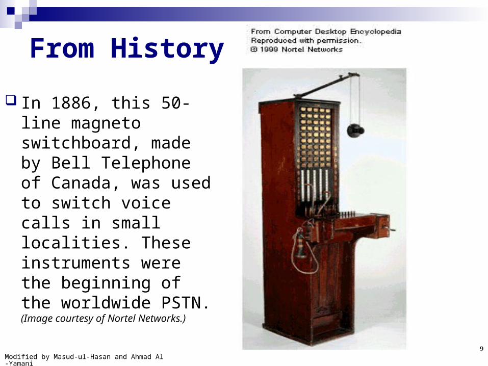
In 1886, this 50-line magneto switchboard, made by Bell Telephone of Canada, was used to switch voice calls in small localities. These instruments were the beginning of the worldwide PSTN. (Image courtesy of Nortel Networks.)
Modified by Masud-ul-Hasan and Ahmad Al-Yamani10
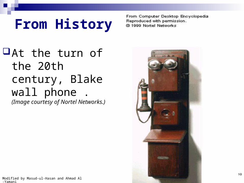
From History
At the turn of the 20th century, Blake wall phone . (Image courtesy of Nortel Networks.)

Modified by Masud-ul-Hasan and Ahmad Al-Yamani11
(telephone switch)
(telephone switch)
Figure 2-3 Basic Telecommunications Infrastructure
Public Switched Telephone Network (PSTN)
The circuits between a residence or business and Central Office (CO) are known as local loops.
A central office (CO) is a facility belonging to local phone company in which calls are switched to their proper destination.
A central office (CO) is a facility belonging to local phone company in which calls are switched to their proper destination.
Telephone calls are established by a device located at CO known as telephone switch.
The telephone switch routes calls to the destination telephone. Requested destinations are indicated by dialing a series of numbers. Which tell the switch whether the call is intra-LATA, or inter-LATA.
All voice traffic destined for outside the local LATA must be handed off to the long distance carrier or IXC.
Long distance carrier doing business in a given LATA maintain a switching office in that LATA known as POP or point of presence. POP handles billing information & routes the call over long distance carrier’s switched network to its POP in the destination LATA. Circuit between POPs
may be via satellite, microwave, fiber optic cable, traditional wiring, or some combination of these media.
Local loop: This is only remaining analog circuit in PSTN.

Modified by Masud-ul-Hasan and Ahmad Al-Yamani12
Residential customer
Business customer
Residential customer
Business customer
Class 1: regional centers
Class 2: sectional centers
Class 3: primary centers
Class 4: toll centers
Class 5: local central office
Local loops
Tandem office
Local loops
Local Carrier's Domain of Influence, Intra-LATA
Class 1: regional centers
Class 2: sectional centers
Class 3: primary centers
Class 4: toll centers
Class 5: local central office
GOLDMAN & RAWLES: ADC3e FIG. 02-04
Representative Voice Network Hierarchy
This is an end office (CO) in hierarchy contains a switch that processes incoming calls, determines the best path to call destination, & establishes the circuit connection.
This establishes the intra-LATA circuit & also handles billing procedures for long distance calls.
This is POP, implies the long distance billing and switching activities.

Modified by Masud-ul-Hasan and Ahmad Al-Yamani13
Representative Voice Network Hierarchy Circuit redundancy offers multiple alternatives paths for call
routing which is a basic idea in voice network hierarchy. If no paths are directly available, then the call is escalated up to
the network hierarchy to the next level of switching office. The overall desire is to keep the call as low as possible in the
hierarchy for quicker call completion and maximization of the cost-effective use of switching offices (i.e. trying to use the least expensive and less number of switching offices).
Higher levels on network hierarchy imply greater switching and transmission capacity as well as greater expense. When calls cannot be completed directly, Class 4 toll centers turn to Class 3 primary centers that subsequently turn to Class 2 sectional centers that turn finally to Class1 regional centers.

Modified by Masud-ul-Hasan and Ahmad Al-Yamani14
Telephone Number Plans Telephone numbers are built using a hierarchical address
method. Numbers tell whether the call is local, intra-LATA, or inter-LATA.
Divided into 3 basic parts: a 2-digit area code starting with 0, a 3-digit exchange, & a 4-digit subscriber number.
To make a call, at a minimum the exchange plus the subscriber number must be dialed. But if the call is within the PBX then only 4(or less)-digit subscriber number will be dialed.
If the call is to a destination outside the source phone’s code, destination area code must be dialed as well.
Modified by Masud-ul-Hasan and Ahmad Al-Yamani15
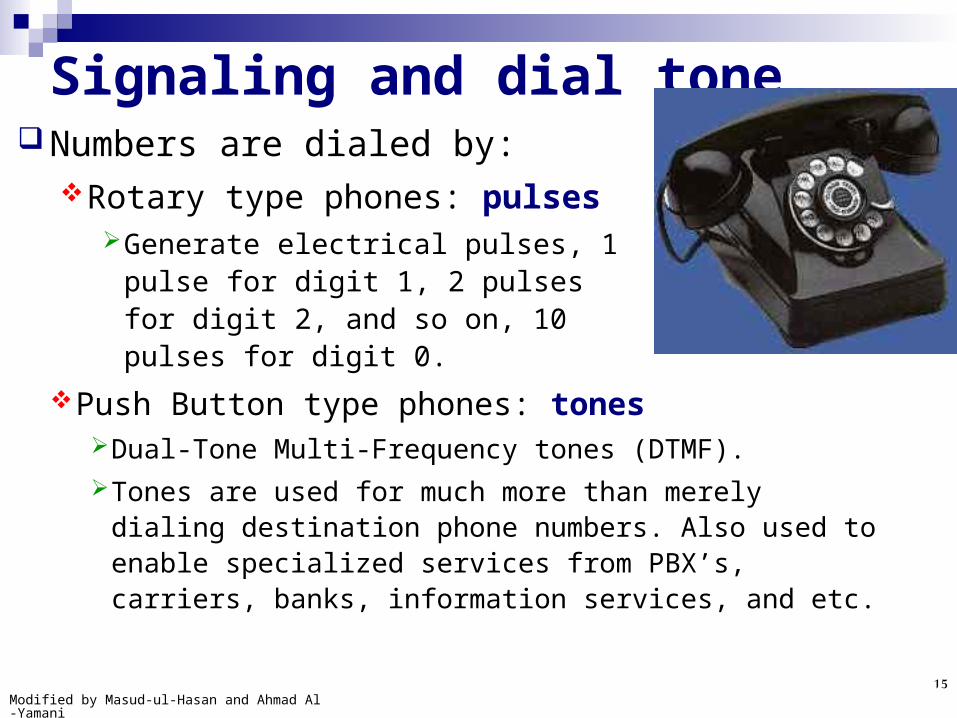
Signaling and dial toneNumbers are dialed by:
Rotary type phones: pulsesGenerate electrical pulses, 1 pulse
for digit 1, 2 pulses for digit 2, and so on, 10 pulses for digit 0.
Push Button type phones: tonesDual-Tone Multi-Frequency tones (DTMF). Tones are used for much more than merely dialing
destination phone numbers. Also used to enable specialized services from PBX’s, carriers, banks, information services, and etc.

Modified by Masud-ul-Hasan and Ahmad Al-Yamani16
Pulse DialingPulse dialing sends digit information to the
CO by momentarily opening and closing (or breaking) the local loop from the calling party to the CO.
This local loop is broken once for the digit 1, twice for 2, etc., and 10 times for the digit 0. As each number is dialed, the loop current is switched on and off, resulting in a number of pulses being sent to your local CO.

Modified by Masud-ul-Hasan and Ahmad Al-Yamani17
Tone Dialing with DTMF
2ABC
1 3DEF
A
4GHI
5JKL
6MNO
B
7PRS
8TUV
9WXY
C
* # D0operator
1209 Hz 1336 Hz 1477 Hz 1633 Hz
941 Hz
852 Hz
770 Hz
697 Hz
Two tones as designated on horizontal (row) and vertical (column) frequency axes are combined to produce
unique tones for each button on the keypad
This column is present only on specialized government phones
Lo
w (
row
) fr
equ
enci
es
High (column) frequencies

Modified by Masud-ul-Hasan and Ahmad Al-Yamani18
Tone Dialing with DTMF1209Hz 1336Hz 1447Hz 1633 Hz
697 Hz 1 2 3 A
770 Hz 4 5 6 B
852 Hz 7 8 9 C
941Hz * 0 # D
Pressing a key on a phone's keypad generates two simultaneous tones, one for the row and one for the column.
These are decoded by the CO to determine which key was pressed.
High Freq.
Low Freq.

Modified by Masud-ul-Hasan and Ahmad Al-Yamani19
System Signaling
In addition to carrying the actual voice signals, the telephone system must also carry information about the call itself.
This is referred to as system signaling or inter-office signaling.
There are two approaches to system signaling: in band and out of band.
Modified by Masud-ul-Hasan and Ahmad Al-Yamani20
In-band Signaling In this system, the signals are sent on the
same channels as the voice data itself.Dial tone makes sure that telephone switch at
CO is ready to serve.Dialing the number sends the phone number
across in the voice bandwidth.If the called party answers the phone, the
remote phone switch comes off the hook and the connection is established.

Modified by Masud-ul-Hasan and Ahmad Al-Yamani21
Out-of-Band Signaling
In this system, the signals are sent on a separate channel as from the voice.
Monitoring of circuit status notification and re-routing in the case of alarms or circuit problems.
The worldwide approved standard for out-of-band signaling is Signaling System 7 (SS7).

Modified by Masud-ul-Hasan and Ahmad Al-Yamani22
Signaling System 7 (SS7)It controls the structure and transmission of
both circuit-related and non-circuit related information via out-of-band signaling between central office switches.
It delivers the out-of-band signaling via a packet switched network physically separate from the circuit switched network that carries the actual voice traffic.
It is nothing more than a packet-switched network.

Modified by Masud-ul-Hasan and Ahmad Al-Yamani23
Signaling System 7 (SS7) Alternate Billing System (ABS) allows a long-
distance call to be billed to a calling party, to the receiver (call collect), or to a third party.
Custom Local Area Signaling Service (CLASS) is a group of services that allows many services local access to the customer’s telephone. E.g., call waiting, call forwarding, call blocking, etc.
Enhanced 800 services allows 800-number portability. Originally, 800 numbers were tied to a specific area code and long-distance provider.
Intelligent Call Processing (ICP) enables the customers to reroute incoming 800 calls among multiple customer service centers, geographically dispersed, in seconds. This is transparent to the caller.

Modified by Masud-ul-Hasan and Ahmad Al-Yamani24
Analog vs. Digital Transmission Transmissions can be either analog or digital.
Analog transmissions, like analog data, vary continuously. Examples of analog data being sent using analog transmissions are voice on phone, broadcast TV and radio.
Digital transmissions are made of square waves with a clear beginning and ending. Computer networks send digital data using digital transmissions.
Data can be converted between analog and digital formats. When digital data is sent as an analog transmission modem
(modulator/demodulator) is used. When analog data is sent as a digital transmission, a codec
(coder/decoder) is used.
Modified by Masud-ul-Hasan and Ahmad Al-Yamani25
Voice Digitization The analog POTS system has been
supplanted in the modern telephone system by a combination of analog and digital transmission technologies.
Converting a voice conversation to digital format and back to analog form before it reaches its destination is completely transparent to phone network users.
There are a limited ways the electrical pulses can be varied to represent an analog signal.

Modified by Masud-ul-Hasan and Ahmad Al-Yamani26
Voice Digitization Techniques
Pulse Amplitude Modulation: (PAM)Varies the amplitude of the electrical pulses.Used in earlier PBX’s.
Pulse Duration Modulation: (PDM/PWM)Varies the duration of electrical pulses.
Pulse Position Modulation: (PPM)Varies the duration between electrical pulses.

Modified by Masud-ul-Hasan and Ahmad Al-Yamani27
Voice Digitization:
PAM
PDM
PPM
876543210
Variable: Pulse amplitude
Constants: Pulse duration, pulse position
analog signal
PAM: Pulse Amplitude Modulation
Sampling rate = 8,000 times/second
1/8000 of a second
876543210
Variable: Pulse duration
Constants: Pulse amplitude, pulse position
analog signal
PDM: Pulse Duration Modulation
876543210
Variable: Pulse position
Constants: Pulse amplitude, pulse duration
analog signal
PPM: Pulse Position Modulation
74 6 5 4 4 46 65 57
74 6 5 4 4 46 65 57

Modified by Masud-ul-Hasan and Ahmad Al-Yamani28
Pulse Code Modulation The most common method used to digitize voice is
Pulse Code Modulation (PCM). No matter how complex the analog waveform happens
to be, it is possible to digitize all forms of analog data, including full-motion video, voices, music, telemetry, and virtual reality (VR) using PCM. Native of .wav
The analog signal amplitude is sampled (measured) at regular time intervals. The sampling rate, or number of samples per second, is several times the maximum frequency of the analog waveform in cycles per second or hertz.
Modified by Masud-ul-Hasan and Ahmad Al-Yamani29
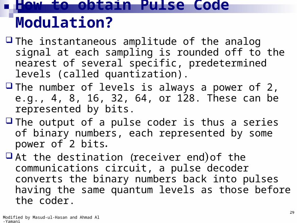
The instantaneous amplitude of the analog signal at each sampling is rounded off to the nearest of several specific, predetermined levels (called quantization).
The number of levels is always a power of 2, e.g., 4, 8, 16, 32, 64, or 128. These can be represented by bits.
The output of a pulse coder is thus a series of binary numbers, each represented by some power of 2 bits.
At the destination (receiver end) of the communications circuit, a pulse decoder converts the binary numbers back into pulses having the same quantum levels as those before the coder.
How to obtain Pulse Code Modulation?
Modified by Masud-ul-Hasan and Ahmad Al-Yamani30
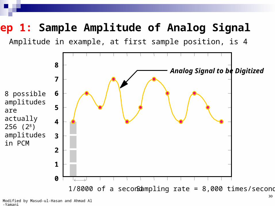
8 possible amplitudes are actually 256 (28) amplitudes in PCM
Analog Signal to be Digitized
Sampling rate = 8,000 times/second1/8000 of a second
8
7
6
5
4
3
2
1
0
Step 1: Sample Amplitude of Analog SignalAmplitude in example, at first sample position, is 4

Modified by Masud-ul-Hasan and Ahmad Al-Yamani31
Step 2: Represent Measured Amplitude in Binary Notation
Binary notation
Power of 2
Value
27 26 25 24 23 22 21 20
128 64 32 16 8 4 2 1
0 0 0 0 0 1 0 0 = 4
8 bits = 1 byte
(0000 0100)2 = (4)10

Modified by Masud-ul-Hasan and Ahmad Al-Yamani32
Step 3: Transmit Coded Digital Pulses Representing Measured Amplitude
0 0 0 0 0 1 0 0
8 transmitted bits = 1 transmitted byte = 1 transmitted sampled amplitude
In this way next few samples will be:(0000 0110)2 = (6)10
(0000 0101)2 = (5)10
(0000 0111)2 = (7)10

Modified by Masud-ul-Hasan and Ahmad Al-Yamani33
T-1 and E-1PCM uses:
8000 samples/sec and 8 bits/sample, so for 1 digitized voice: 8000 x 8 = 64,000 bps is the required bandwidth.
This is known as a DS-0 (basic unit of voice data trans.) 24 DS-0s = 24 x 64 Kbps = 1,536 Kbps = 1.536 Mbps 1 framing bit/sample x 8000 samples/sec = 8000 framing bps
= 8 Kbps 8 Kbps + 1,536 Kbps = 1,544 Kbps = Trans. cap. of T-1 T-1 (1.544 Mbps) can carry 24 simultaneous voice
conversations digitized via PCM.
European equivalent standard is E-1 (2.048Mbps)

Modified by Masud-ul-Hasan and Ahmad Al-Yamani34
T-1 and E-1PCM uses:
8000 samples/sec and 8 bits/sample, so for 1 digitized voice: 8000 x 8 = 64,000 bps is the required bandwidth.
This is known as a DS-0 (basic unit of voice data trans.) 24 DS-0s = 24 x 64 Kbps = 1,536 Kbps = 1.536 Mbps 1 framing bit/sample x 8000 samples/sec = 8000 framing bps
= 8 Kbps 8 Kbps + 1,536 Kbps = 1,544 Kbps = Trans. capacity of T-1 T-1 (1.544 Mbps) can carry 24 simultaneous voice
conversations digitized via PCM.
European equivalent standard is E-1 (2.048Mbps)

Modified by Masud-ul-Hasan and Ahmad Al-Yamani35
Adaptive Differential PCM (ADPCM)
Each voice channel uses 4 bits instead of 8 bits. So, for 1 digitized voice: 8000 x 4 = 32,000 bps is the
required bandwidth. The standard for 32-Kbps is known G.721
ADPCM supports 48 simultaneous conversations over a T1 circuit.
The G.721 is used as a quality reference point for voice transmissions (Toll Quality).
ADPCM is used to send sound on fiber-optic long-distance lines as well as to store sound along with text, images, and code on a CD-ROM.
Modified by Masud-ul-Hasan and Ahmad Al-Yamani36
Voice Compression ADPCM is also known as voice compression
technique because of its ability to transmit 24 digitized voice conversations in half the bandwidth required by PCM.
Other more advanced techniques employ DSPs (Digital Signal Processors) that take the PCM code & further manipulate and compress it.
DSPs are able to compress voice as little as 4800 bps. Efficiency: 13 times more than PCM. Voice compression may be accomplished by stand
alone units, or by integral modules within other equipment.

Modified by Masud-ul-Hasan and Ahmad Al-Yamani37
Although the PSTN is the cheapest and most effective way to transmit voice, alternative methods are do exist.
Some of them are:Voice over the Internet (VoIP)
Voice over Frame relay (VoFR)
Voice over ATM (VoATM)
Voice Transmission Alternatives to PSTN

Modified by Masud-ul-Hasan and Ahmad Al-Yamani38
VOIP refers to any technology used to transmit voice over any network running the IP protocol (in packets).
It is not confined to use on the Internet only, can be used in any of the following:Modem based point-to-point connectionsLocal area networks (LANs)Private Internets (Intranets)
It can be successfully deployed with:VOIP client softwareusing a PC with sound card, microphone, and speakersgateways are being established to allow Internet voice
callers to reach regular telephone users as well.
Voice over the Internet (VOIP)

Modified by Masud-ul-Hasan and Ahmad Al-Yamani39
VOIP Transmission Technology
REQUIRED CLIENT TECHNOLOGY
Internet
Access
Client workstation Internal
External
-or-
Modem
ONLY required for
dial-up connections
ONLY
required for
Internet-
based voice
transmission
LAN
connection
ONLY
required for
LAN-based
voice
transmission
Voice/sound technology
sound card
speakers
microphone
IP-based Voice Client
software
and
/ o
r
and
/ o
r
and
and
Modified by Masud-ul-Hasan and Ahmad Al-Yamani40
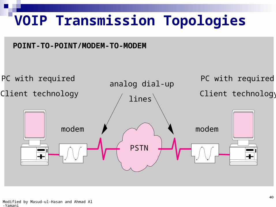
PSTN
POINT-TO-POINT/MODEM-TO-MODEM
modemmodem
analog dial-up
lines
PC with required
Client technology
PC with required
Client technology
VOIP Transmission Topologies

Modified by Masud-ul-Hasan and Ahmad Al-Yamani41
LAN hub
LOCAL AREA NETWORK
LAN attached PCs with required
Client technology.IP protocols REQUIRED
VOIP Transmission Topologies

Modified by Masud-ul-Hasan and Ahmad Al-Yamani42
router router
LAN hubs
INTERNET/INTRANET
LAN attached PCs with required Client technology. IP protocols REQUIRED
Internet -or-
Intranet
VOIP Transmission Topologies

Modified by Masud-ul-Hasan and Ahmad Al-Yamani43
Voice over Frame relay Initially deployed for data transmission but is now
capable of delivering voice transmissions as well.Frame relay encapsulates segments of a data transfer
session into variable length frames.For longer data transfers, longer frames and for shorter
data transfers, shorter frames are used.These variable length frames introduce varying
amounts of delay resulting from processing by intermediate switches on the frame relay network.
This variable length delay works well with data transmission but is not acceptable in voice transmission because it is sensitive to delay.

Modified by Masud-ul-Hasan and Ahmad Al-Yamani44
Voice over Frame relay Frame relay access device (FRAD) accommodates both
voice and data: Voice prioritization: FRAD distinguish between voice and data traffic (because of
tagging), priority given to voice over data Data frame size limitation: long data frames must be segmented into multiple
smaller frames to limit delays Separate voice and data queues: within the FRAD
Voice conversations require 4 – 16 Kbps of bandwidth. This dedicated bandwidth is reserved as an end-to-end
connection through frame relay network called Permanent Virtual Circuit (PVC).
Voice conversation can take place only between locations directly connected to a frame relay network.
No current standards defined between frame- relay networks and the voice based PSTN.

Modified by Masud-ul-Hasan and Ahmad Al-Yamani45
Voice Transmission over a Frame Relay Network
FR FRvoice
data
voice
data
voice and data
voice and data
Local Area Network
Telephone service Telephone service
Local Area Network
PBX PBX
PSTN
NO voice interoperability between Frame Relay and
PSTN networks
FRAD prioritizes voice
traffic
FRAD prioritizes voice
traffic
Frame Relay Network

Modified by Masud-ul-Hasan and Ahmad Al-Yamani46
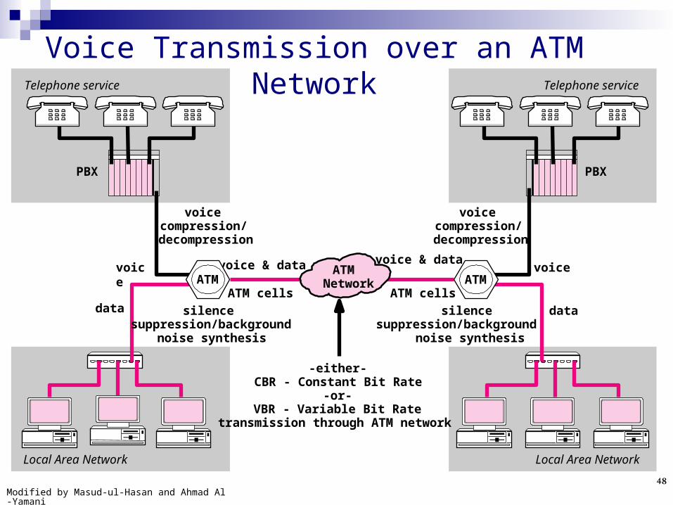
Voice over ATM ATM (Asynchronous Transfer Mode) is a switched-based
WAN service using fixed-length frames (called cells). Fixed length cells assures fixed time processing by ATM
switches enabling predictable delay and delivery time. Voice transmitted using Constant Bit Rate (CBR)
bandwidth reservation scheme. CBR does not make optimal use of bandwidth because
of moments of silence. Most common method: reserve a CBR of 64Kbps for one
conversation digitized via PCM.

Modified by Masud-ul-Hasan and Ahmad Al-Yamani47
Optimizing voice over ATM Voice Compression: Achieved via ITU, G series of
standards, algorithms vary in amount of bandwidth required to transmit toll quality voice:G.726: 48, 32, 24 or 16 KbpsG.728: 16 KbpsG.729: 8 Kbps
Silence suppression: Cells containing silence are not allowed and replaced at the receiver with synthesized background noise. It reduces the amount of cells transmitted for a given voice conversation by 50%.
Use of VBR (Variable bit rate): Combines positive attributes of both voice compression and silence suppression. By using bandwidth only when someone is talking, remaining bandwidth is available for data transmission or other voice conversations.
Modified by Masud-ul-Hasan and Ahmad Al-Yamani48
Voice Transmission over an ATM Network
ATM Network
voice
data
voice
data
Local Area Network
Telephone service Telephone service
Local Area Network
PBX PBX
-either- CBR - Constant Bit Rate
-or- VBR - Variable Bit Rate
transmission through ATM network
silence suppression/background
noise synthesis
ATM cells
silence suppression/background
noise synthesis
ATM cells
voice compression/
decompression
voice compression/
decompression
voice & dataATMATM
voice & data

Modified by Masud-ul-Hasan and Ahmad Al-Yamani49
Voice/Data Multiplexers Organizations have traditionally chosen to link voice
and data transmission over long distances via leased digital transmission services such as T-1/E-1.
From a business perspective, switched services (frame relay, ATM) are charged according to usage and leased lines are charged according to flat monthly rate whether they are used or not.
Many businesses found that usage based pricing can produce significant savings.
A voice/data multiplexer simultaneously transmits digitized voice and data over a single digital transmission service.
Modified by Masud-ul-Hasan and Ahmad Al-Yamani50
Integrated Services Digital Network (ISDN)
A newer switched digital service used for small business and residential users.
ISDN BRI (Basic Rate Interface) service offers two 64Kbps channels.
It offers two 64 Kbps channels, one for voice while the other for data. Both can be used simultaneously.

Modified by Masud-ul-Hasan and Ahmad Al-Yamani51
Simultaneous Voice/Data Transmission with ISDN
PC
ISDN
ISDN modem
data/voice
Analog Phone
PC
ISDN modem
data/voice
Analog Phone
data and voice on
separate channels
digital digital
64Kbps voice
64Kbps data

Modified by Masud-ul-Hasan and Ahmad Al-Yamani52
Wireless Voice TransmissionModern wireless telephones are based on a
cellular model. A wireless telephone system consists of a
series of cells that surround a central base station, or tower.
The term “cellular phone” or “cell phone” comes from the cellular nature of all wireless networks.

Modified by Masud-ul-Hasan and Ahmad Al-Yamani53
Wireless Voice Transmission

Modified by Masud-ul-Hasan and Ahmad Al-Yamani54
Analog Cellular (1G)Advanced Mobile Phone Service (AMPS)
operate in the 800MHz frequency range.
carried just voice traffic.
have significant limitations.
offer relatively poor signal quality.
static and interference are inherent with the
system.
can handle relatively few concurrent calls per cell.

Modified by Masud-ul-Hasan and Ahmad Al-Yamani55
Wireless Voice Transmission
Elements of digital cellular
Modified by Masud-ul-Hasan and Ahmad Al-Yamani56
Digital Cellular (2G) carriers have steadily moved to digital cellular
systems. the call is digitized at the telephone handset and
sent in a digital format to the tower. quality is greatly improved. more calls to share the common bandwidth in a cell
concurrently. better equipped to support wireless data
transmission.
Modified by Masud-ul-Hasan and Ahmad Al-Yamani57
Digital Cellular Standards
TDMA and CDMA are the two access
methodologies used in digital cellular
systems.
Both offer significant capacity increases
compared to AMPS analog cellular
systems.

Modified by Masud-ul-Hasan and Ahmad Al-Yamani58
TDMA
TDMA achieves more than one conversation per frequency by assigning timeslots to individual conversations.

Modified by Masud-ul-Hasan and Ahmad Al-Yamani59
Global System for Mobile Communication (GSM)
A new service layer overlies TDMA.It provides a standardized billing interface
(consumer can roam seamlessly between the GSM network of different companies), offers enhanced data services.
In GSM, SIM card store the user’s information, his phone number, contacts, and so on. So easy to change the phone set, no need of programming of new phone set.

Modified by Masud-ul-Hasan and Ahmad Al-Yamani60
CDMA
CDMA attempts to maximize the number of calls transmitted within a limited bandwidth by using a spread spectrum transmission technique.

Modified by Masud-ul-Hasan and Ahmad Al-Yamani61
CDMA Spread spectrum transmission technique is like
datagram connectionless service.
In a CDMA system, encoded voice is digitized and
divided into packets.
These packets are tagged with “codes”.
The packets then mix with all of the other packets of
traffic in the local CDMA network as they are routed
towards their destination.
The receiving system only accepts the packets with
the codes destined for it.

Modified by Masud-ul-Hasan and Ahmad Al-Yamani62
Different GenerationsAMPS 1G (1st Generation) max. 14.4KbpsTDMA & CDMA 2G (2nd Generation) 9.6-
14.4KbpsGPRS (General Packet Radio Service) 2.5G
(Advanced 2nd Generation) 56Kbps-115KbpsEDGE (Enhanced Data for GSM Evolution) &
EV-DO (Evolution Data Only) 3G (3rd Generation) 128Kbps for moving car and 2Mbps for fixed.
Commercially available in 2010 4G (4th Generation) 100 Mbps

Modified by Masud-ul-Hasan and Ahmad Al-Yamani63
Private Branch ExchangesA PBX is just a privately owned, smaller version
but similar in function to a public exchange.A PBX is exclusively used by the organization
and physically located on the organization’s premises.
Provides an interface between users and the shared network (PSTN).
Additional services offered by a PBX allow users to use their phones more efficiently and effectively.
Medium to large organizations can save a lot of money by using a PBX.

Modified by Masud-ul-Hasan and Ahmad Al-Yamani64
PBX Architecture PBX overall functionality and added features are controlled
by software programs running on specialized computers within the PBX area sometimes referred to as the PBX CPU, stored program control, or common control area.
User phones are connected to PBX via slide-in modules or cards known as line cards, port cards, or station cards.
Connection of PBX to outside world is accomplished via Trunk cards.
Starting with an open chassis or cabinet with power supply and backbone, cards can be added to increase PBX capacity either for the user extensions or outside connections.
Additional cabinets can be cascaded for expandability.

Modified by Masud-ul-Hasan and Ahmad Al-Yamani65
PBX Physical Architecture
CPU or common control
Switching matrix
Sta
tio
n c
ard
Tru
nk
car
d
Sta
tio
n c
ard
Sta
tio
n c
ard
Sta
tio
n c
ard
Sta
tio
n c
ard
Sta
tio
n c
ard
Sta
tio
n c
ard
Sta
tio
n c
ard
Users and phones
(stations)
PBX
Outside trunks

Modified by Masud-ul-Hasan and Ahmad Al-Yamani66
PBX Technology Analysis
PBX features and services tend to fall into three categories:
1. provide users with flexible usage of PBX resources.
2. provide for data/ voice integration.
3. control and monitor the use of those PBX resources.

Modified by Masud-ul-Hasan and Ahmad Al-Yamani67
1. Flexible Usage - Voice Based Features and Services
Common features: Conference calling, Call forwarding /divert, Redialing, Call transfer, Speed dialing, Call hold, Hunting, etc.
Least Cost Routing: Selecting lowest price long distance carriers.
Automatic Call distribution: Incoming calls are routed directly to certain extensions without going through a central switchboard.
Call pickup: Allows a user to pickup or answer another user’s phone without forwarding.
Paging: Ability to use paging speakers in a building.

Modified by Masud-ul-Hasan and Ahmad Al-Yamani68
2. Data/Voice Integration – Features and Services
Data is transmitted either:through the PBX via a dedicated connection ORa hybrid voice/data phone is used to transmit both
voice and data simultaneously over a single connection.
Features:ISDN (Integrated Services Digital Network) support,
T-1 / E-1 interfaces support (codecs included or not), Data interfaces, modem pooling, printer sharing, file sharing, video conferencing, etc.

Modified by Masud-ul-Hasan and Ahmad Al-Yamani69
3. Control and Monitoring – Features and Services
Basic: (e.g.)Limiting access to outside lines from certain
extensions.Advanced:
Call accounting system: program run on a separate PC directly connected to the PBX.
Process within the PBX known as Station Message Detail Recording (SMDR) where an individual detail record is generated for each call.
Used for spotting abuse, both incoming and outgoing calls can be tracked.
Allocating phone usage on a departmental basis.

Modified by Masud-ul-Hasan and Ahmad Al-Yamani70
Call Accounting Systems Installation
CPU or common control
Switching matrix
Sta
tio
n c
ard
Tru
nk
card
Sta
tio
n c
ard
Sta
tio
n c
ard
SM
DR
ou
tpu
t
Users and phones
(stations)
PBX
Outside trunk
PC-based, call accounting system
Report printer
Usually an RS-232 connection
Call records are either saved or discarded based on call
filtering settings

Modified by Masud-ul-Hasan and Ahmad Al-Yamani71
Auxiliary Voice Related Services
Auxiliary add-on device that provides the following services:Automated attendantVoice mailVoice response units (VRU), e.g., Interactive
voice response (IVR).Voice processor: e.g. speech recognitionVoice server: a LAN based server that stores,
and delivers digitized voice messages. Used with voice mail system.
Music / ads on hold

Modified by Masud-ul-Hasan and Ahmad Al-Yamani72
Computer Telephony Integration (CTI)
CTI seeks to integrate the computer and the telephone to enable increased productivity not otherwise possible by using the two devices in a non-integrated fashion.
CTI is not a single application, but an ever-widening array of possibilities spawned by the integration of telephony and computing.

Modified by Masud-ul-Hasan and Ahmad Al-Yamani73
Computer Telephony Integration (CTI)CTI attempts to integrate the two most common
productivity devices, the phone and the computer to increase productivity.
Examples of the integration:Call control: allows users to control their telephone
functions through their computer, on-line phone books, on-line display and processing of voice mail.
Interactive Voice Response: E.g., IVR systems used by banks, carriers, etc.
Unified massages: Voice mail, e-mail, faxes, pager messages to be displayed on a single graphical screen. Then can be forwarded, replied, deleted, etc.
Modified by Masud-ul-Hasan and Ahmad Al-Yamani74
CTI Architectures
CTI is commonly implemented in one of the following three architectures:PBX-to-host interfaces (Integration of PBX with
mainframe, minicomputers, etc. for call center and office automation applications)
Desktop CTIClient/server CTI
Modified by Masud-ul-Hasan and Ahmad Al-Yamani75
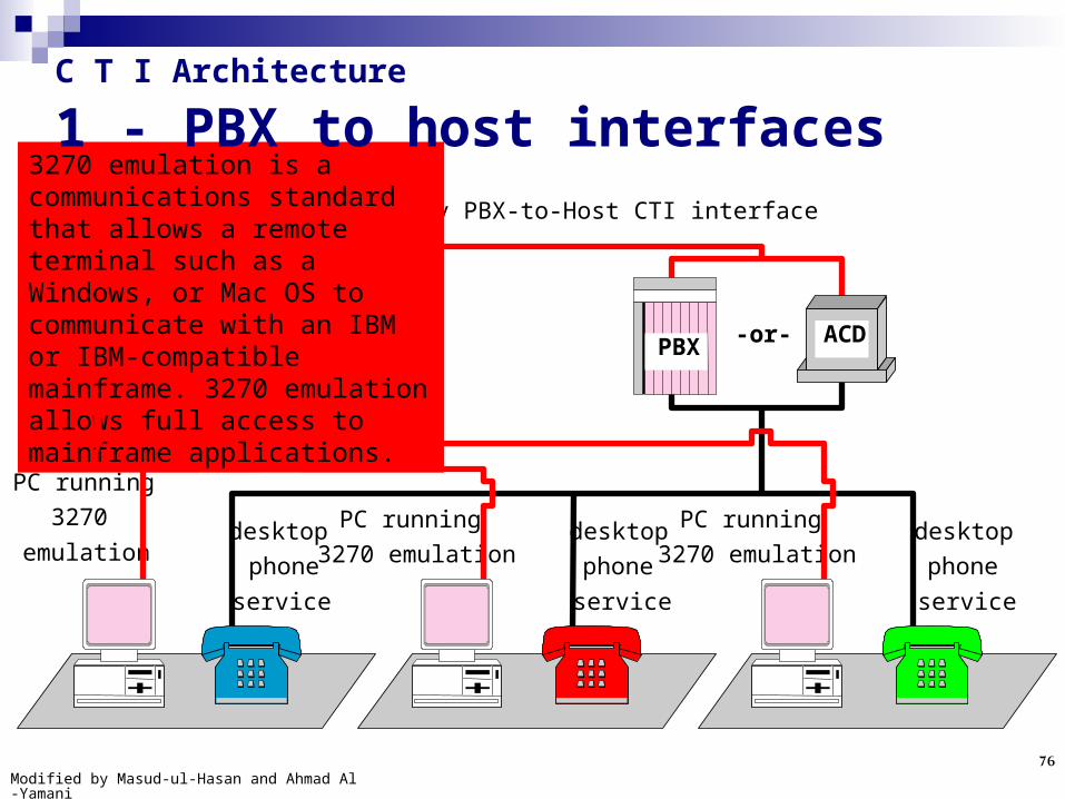
C T I Architecture 1 - PBX to host interfaces
Before the arrival of open systems Computer Telephony Integration APIs such as TAPI, TSAPI, each PBX vendor had its own PBX-to-host interface specifications.
In PBX-to-host interface CTI was achieved by linking mainframes to PBXs via PBX-to-host-interface.
Compatible applications with computer and PBX. Systems linked to an automatic call distribution unit
(ACD) All phones are controlled by CTI application running
on mainframe computer. Expensive systems.
Modified by Masud-ul-Hasan and Ahmad Al-Yamani76
PC running
3270
emulation
PC running
3270 emulation
PC running
3270 emulationdesktop
phone
service
desktop
phone
service
desktop
phone
service
mainframe
computerPBX ACD
CTI
applications -or-
proprietary PBX-to-Host CTI interface
3270 emulation is a communications standard that allows a remote terminal such as a Windows, or Mac OS to communicate with an IBM or IBM-compatible mainframe. 3270 emulation allows full access to mainframe applications.
C T I Architecture 1 - PBX to host interfaces

Modified by Masud-ul-Hasan and Ahmad Al-Yamani77
C T I Architecture
2 - Desktop CTI Also known as, first party call control Less expensive alternative to PBX-to-host
architecture. PC’s are equipped with telephony boards and
associated call control software. Each PC controls only the telephone to which it is
attached. No overall automatic call distribution across multiple
agents and their phones. No sharing of call related data among the desktop
CTI PC’s.

Modified by Masud-ul-Hasan and Ahmad Al-Yamani78
C T I Architecture
2 - Desktop CTI
CTI card
CTI card
PBX
PSTN
-or-
desktop CTI application
desktop CTI
application

Modified by Masud-ul-Hasan and Ahmad Al-Yamani79
C T I Architecture
3 - Client/Server C T I CTI server computer interfaces to the PBX or ACD to
provide overall system management. Individual client based CTI applications execute on
multiple client PCs. Multiple CTI applications on multiple client PCs can
share the information supplied by the single CTI Server.
Offers overall shared control of the PBX-to-host CTI architecture at a cost closer to that of the desktop architecture.

Modified by Masud-ul-Hasan and Ahmad Al-Yamani80
C T I Architecture
3 - Client/Server C T I
CTI client applications
CTI client applications
CTI client applications
desktop phone service
desktop phone service
desktop phone service
data server
CTI server
CTI Server applications
customer information
PBX ACD-or-


