Page 1
1
Optimization of Reinforcement Methods for Non-round Pressure Vessels
By
Shawn McMahon
A Presentation of a Thesis
In Partial Fulfillment of the
Requirements for the Degree of
Masters of Science
Major Subject: Mechanical Engineering
Page 2
2
Abstract
For a number of reasons the exhaust of a modern gas turbine engine is moving away from the conventional round pipe, and being replaced by one with an elliptical cross section. However, designing a low weight, non-round pressure vessel is more challenging than a typical round pressure vessel.
The problem posed is how to create the lightest weight round to elliptical pressure vessel. In order to accomplish this, analytical models were created and optimized based on a number of parameters. Two different optimization approaches were investigated.
The results showed that the first optimization method was simpler to build and optimize, but provided less than optimal weights. The second optimization method was much more complicated to build, was more sensitive to the controls of the optimization, but provided the lightest results.
Page 3
3
Optimization Methods
ANSYS was used as the finite element solver. The first optimization method used was shape optimization, also called
topological optimization. Simple ANSYS commands Pseudo-density manipulation Limited element selection and optimization controls
Simulated topological optimization. Design optimization of shell thickness Simulated manufacturability constraints
The second method used was design optimization. Requires parametric model to be built with APDL More difficult but more functionality Yields better results
Page 4
4
Pressure Vessel Description
Dimensions:
• 40” diameter
• 50” long
• 12” spool piece
12” spool pieceEdge fixed in all DOF
Material: Ti-6Al-V4
Constraints: Edge of spool fixed in all DOF
Load: 80 psi
A B A BModel # Ratio Major Minor Minor Major
1 1.0000 20.000 20.000 N/A N/A2 1.5000 24.495 16.330 1.22474 0.816503 2.0000 28.285 14.142 1.41423 0.707104 2.5000 31.623 12.649 1.58115 0.632455 3.0000 34.641 11.547 1.73205 0.577356 3.5000 37.416 10.691 1.87082 0.534537 4.0000 40.000 10.000 2.00000 0.50000
Scale FactorEllipse Dimensions
Table of Ellipse Parameters
Page 5
5
Quick Test of Topological Opt.
Dimensions:
• 10 inch long
• 1 inch high
Elements:
• Plane82
Goal:
• 75 percent reduction in volume
P
Results:
Page 6
6
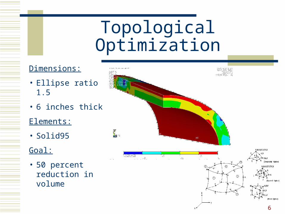
Topological Optimization
Dimensions:
• Ellipse ratio 1.5
• 6 inches thick
Elements:
• Solid95
Goal:
• 50 percent reduction in volume
Page 7
7
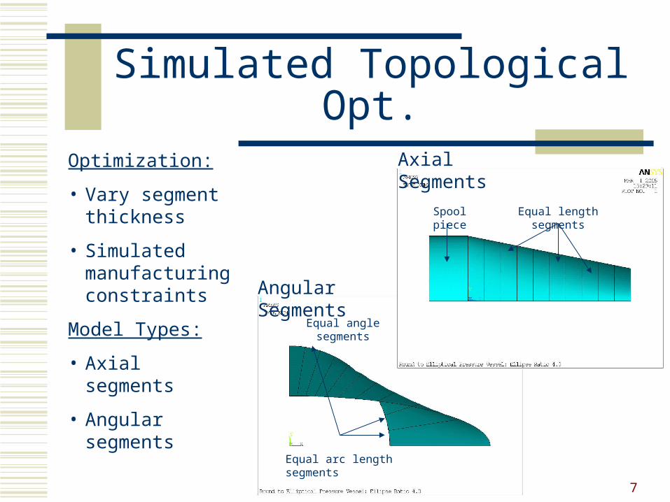
Simulated Topological Opt.
Optimization:
• Vary segment thickness
• Simulated manufacturing constraints
Model Types:
• Axial segments
• Angular segments
Equal arc length segments
Equal angle segments
Angular Segments
Equal length segments
Axial Segments
Spool piece
Page 8
8
Simulated Topo. Opt. Results
Model 2 Model 3 Model 4 Model 5 Model 6 Model 7VTOT 746 1004 1237 1408 1537 1739DMAX 0.49973 0.51051 0.51035 0.51127 0.52229 0.50790T1 0.11047 0.10944 0.11520 0.12810 0.22251 0.19416T2 0.10797 0.10932 0.10955 0.10881 0.27498 0.23423T3 0.10758 0.10880 0.10988 0.10790 0.27376 0.29415T4 0.10869 0.11267 0.19896 0.25083 0.29698 0.32235T5 0.15409 0.25936 0.37540 0.44148 0.37598 0.50012T6 0.29878 0.44673 0.57943 0.65027 0.68499 0.86364T7 0.48878 0.66764 0.79971 0.86712 0.87785 0.94266T8 0.69788 0.91337 1.05967 1.12408 0.94874 0.75389T9 0.96575 1.12382 1.14631 1.03347 0.60998 0.51454T10 1.51187 2.04907 2.46349 2.86049 3.39258 4.01248
Results Table
0.0
0.5
1.0
1.5
2.0
2.5
3.0
3.5
4.0
4.5
1 2 3 4 5 6 7 8 9 10
Pressure Vessel Axial Segment
Sh
ell T
hic
knes
s (i
n)
Model 1 Model 2 Model 3 Model 4 Model 5 Model 6 Model 7
Shell Thickness per Axial Segment
Sample Results Screen Shot
Results:
• Aft most segment always thickest
• Segment 7 and/or 8 thicker in highly elliptical models
Page 9
9
Simulated Topo. Opt. Results
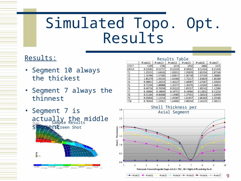
Model 2 Model 3 Model 4 Model 5 Model 6 Model 7VTOT 1189 1786 2214 2592 2886 3175DMAX 0.53585 0.52757 0.52329 0.50587 0.51424 0.51439T1 1.25551 1.64626 1.82651 1.95039 2.03334 2.07348T2 1.16706 1.57205 1.83817 1.96738 1.97194 1.98805T3 1.05279 1.44335 1.64386 1.75217 1.83029 1.86388T4 0.90051 1.28259 1.46227 1.60907 1.67687 1.69969T5 0.71594 1.08000 1.25377 1.36976 1.43269 1.46014T6 0.48734 0.76950 0.92223 1.03357 1.09142 1.12506T7 0.10886 0.10889 0.10751 0.10986 0.12032 0.13234T8 0.51284 0.86880 1.14905 1.37951 1.50323 1.63999T9 0.65026 1.13154 1.49307 1.81857 2.06284 2.29106T10 0.70264 1.23961 1.64802 2.00344 2.26225 2.50213
Results Table
0.0
0.5
1.0
1.5
2.0
2.5
3.0
1 2 3 4 5 6 7 8 9 10
Pressure Vessel Angular Segment (1 = TDC, 10 = Right, Aft Looking Fwd)
Sh
ell T
hic
knes
s (i
n)
Model 1 Model 2 Model 3 Model 4 Model 5 Model 6 Model 7
Shell Thickness per Axial Segment
Sample Results Screen Shot
Results:
• Segment 10 always the thickest
• Segment 7 always the thinnest
• Segment 7 is actually the middle segment
Page 10
10
Design Optimization
Model Types:
• Axially spaced ribs
• Addition of four circumferentially spaced ribs
Optimization Parameters:
• Number of ribs
• Distribution of ribs
• Position of first ribs
• Rib height
• Shell thickness
0
5
10
15
20
25
30
35
40
45
50
1 2 3 4 5 6
Rib Number
Rib
Po
siti
on
fro
m F
orw
ard
Ed
ge
(in
)
Linear: D = 1 Cubic: D = 2 Quadratic: D = 3
Model Type A
Model Type B
Mesh Elements
Shell181
Beam188
Page 11
11
Design Optimization
Optimization Flowchart:
Page 12
12
Design Optimization Results
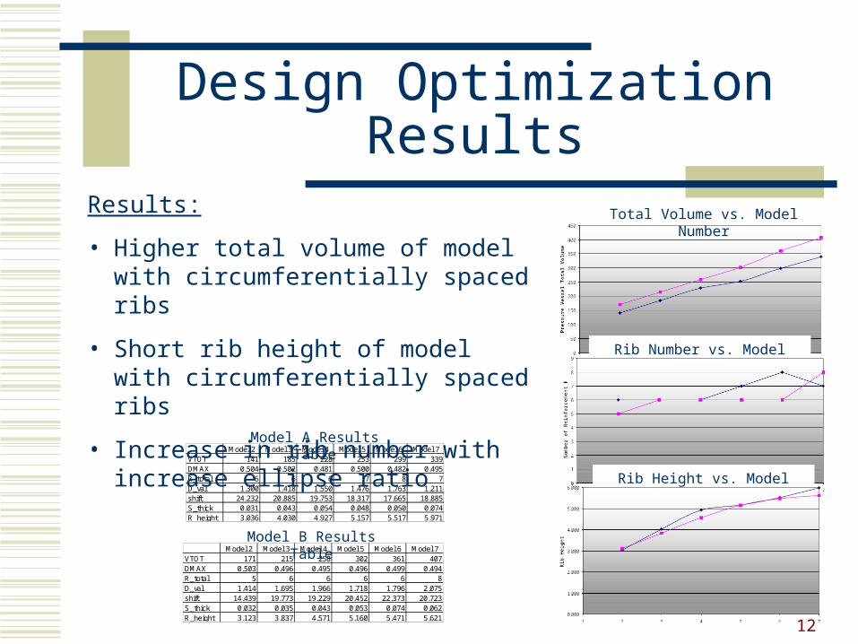
Model 2 Model 3 Model 4 Model 5 Model 6 Model 7VTOT 141 185 228 253 299 339DMAX 0.504 0.502 0.481 0.500 0.482 0.495R_total 6 6 6 7 8 7D_val 1.300 1.418 1.550 1.476 1.763 1.211shift 24.232 20.885 19.753 18.317 17.665 18.885S_thick 0.031 0.043 0.054 0.048 0.050 0.074R_height 3.036 4.030 4.927 5.157 5.517 5.971
Model A Results Table
Model 2 Model 3 Model 4 Model 5 Model 6 Model 7VTOT 171 215 258 302 361 407DMAX 0.503 0.496 0.495 0.496 0.499 0.494R_total 5 6 6 6 6 8D_val 1.414 1.695 1.966 1.718 1.796 2.075shift 14.439 19.773 19.229 20.452 22.373 20.723S_thick 0.032 0.035 0.043 0.053 0.074 0.062R_height 3.123 3.837 4.571 5.160 5.471 5.621
Model B Results Table
Total Volume vs. Model Number
Rib Number vs. Model Number
Rib Height vs. Model Number
Results:
• Higher total volume of model with circumferentially spaced ribs
• Short rib height of model with circumferentially spaced ribs
• Increase in rib number with increase ellipse ratio
Page 13
13
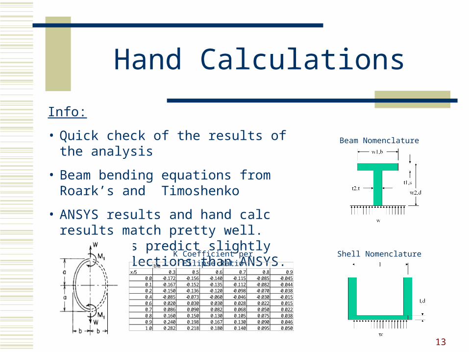
Hand Calculations
Info:
• Quick check of the results of the analysis
• Beam bending equations from Roark’s and Timoshenko
• ANSYS results and hand calc results match pretty well. Hand calcs predict slightly lower deflections than ANSYS.
b/ax/S 0.3 0.5 0.6 0.7 0.8 0.9
0.0 -0.172 -0.156 -0.140 -0.115 -0.085 -0.0450.1 -0.167 -0.152 -0.135 -0.112 -0.082 -0.0440.2 -0.150 -0.136 -0.120 -0.098 -0.070 -0.0380.4 -0.085 -0.073 -0.060 -0.046 -0.030 -0.0150.6 0.020 0.030 0.030 0.028 0.022 0.0150.7 0.086 0.090 0.082 0.068 0.050 0.0220.8 0.160 0.150 0.130 0.105 0.075 0.0380.9 0.240 0.198 0.167 0.130 0.090 0.0461.0 0.282 0.218 0.180 0.140 0.095 0.050
K Coefficient per Ellipse Ratio
Beam Nomenclature
Shell Nomenclature