44
1 PETE 411 Well Drilling Lesson 35 Wellbore Surveying Methods
| Date post: | 23-Dec-2015 |
| Category: |
Documents |
| Upload: | jacob-morton |
| View: | 300 times |
| Download: | 21 times |
1
PETE 411
Well Drilling
Lesson 35
Wellbore Surveying Methods
2
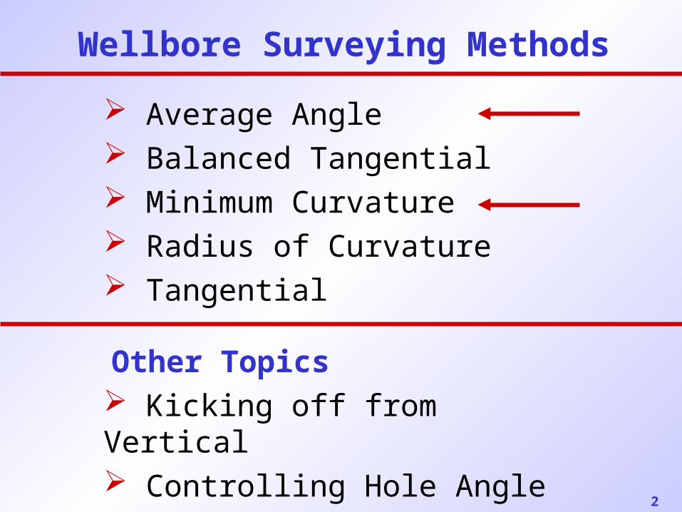
Wellbore Surveying Methods
Average Angle Balanced Tangential Minimum Curvature Radius of Curvature Tangential
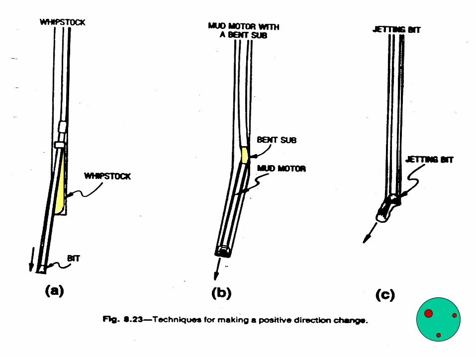
Other Topics Kicking off from Vertical Controlling Hole Angle
3
Read:
Applied Drilling Engineering, Ch.8 (~ first 20 pages)
Projects:
Due Monday, December 9, 5 p.m.
( See comments on previous years’ design projects )

4
Homework Problem #18
Balanced Cement Plug
Due Friday, December 6
5
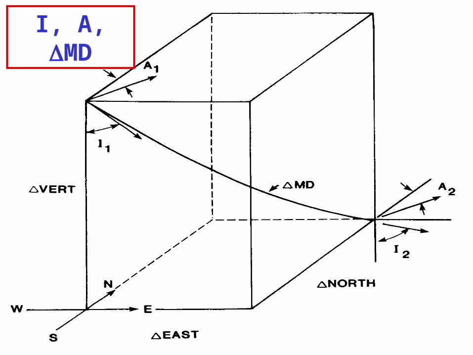
I, A, MD
6
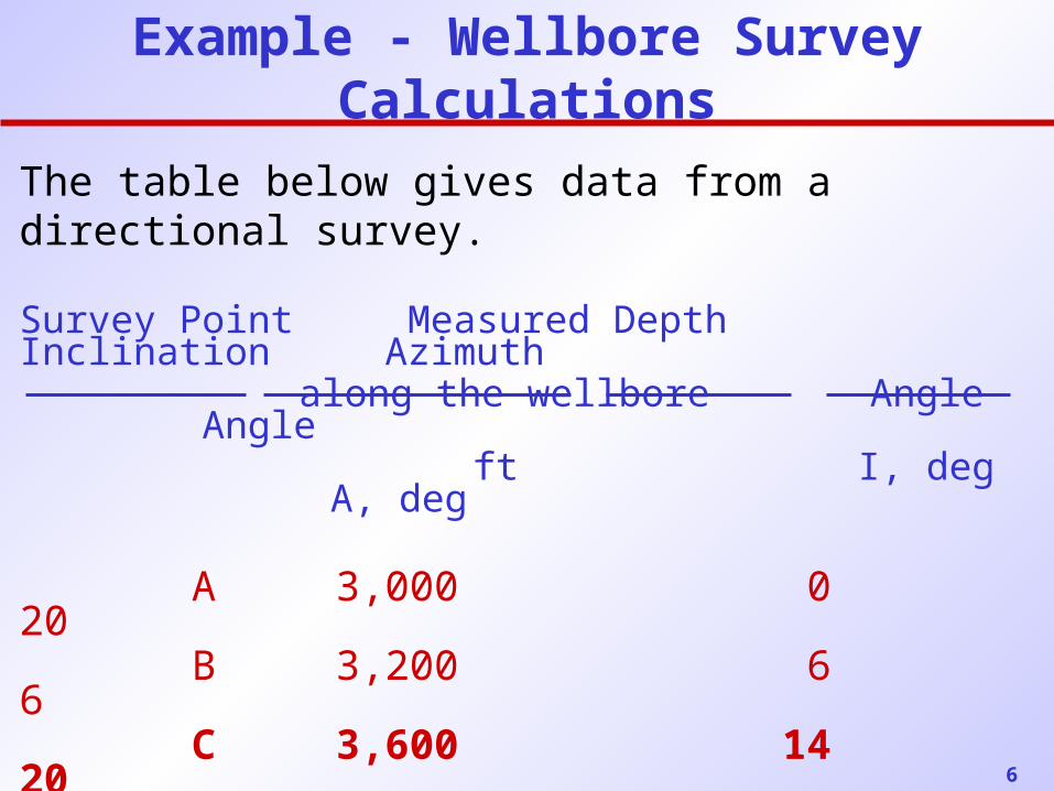
Example - Wellbore Survey Calculations
The table below gives data from a directional survey.
Survey Point Measured Depth Inclination Azimuth along the wellbore Angle Angle
ft I, deg A, deg
A 3,000 0 20 B 3,200 6 6 C 3,600 14 20 D 4,000 24 80
Based on known coordinates for point C we’ll calculate the coordinates of point D using the above information.
7
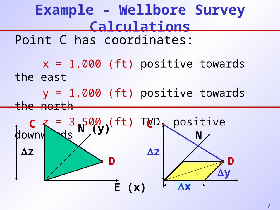
Example - Wellbore Survey Calculations
Point C has coordinates:
x = 1,000 (ft) positive towards the east
y = 1,000 (ft) positive towards the north
z = 3,500 (ft) TVD, positive downwards
z
E (x)
N (y)C
Dz
N
D
C
yx
8
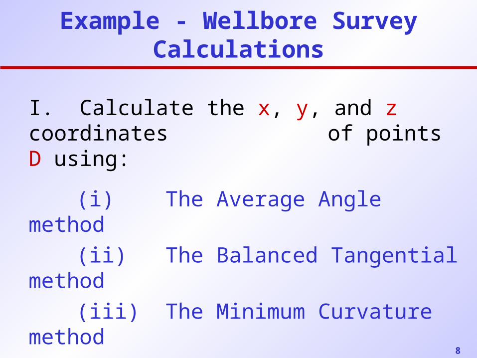
Example - Wellbore Survey Calculations
I. Calculate the x, y, and z coordinates of points D using:
(i) The Average Angle method
(ii) The Balanced Tangential method
(iii) The Minimum Curvature method
(iv) The Radius of Curvature method
(v) The Tangential method
9
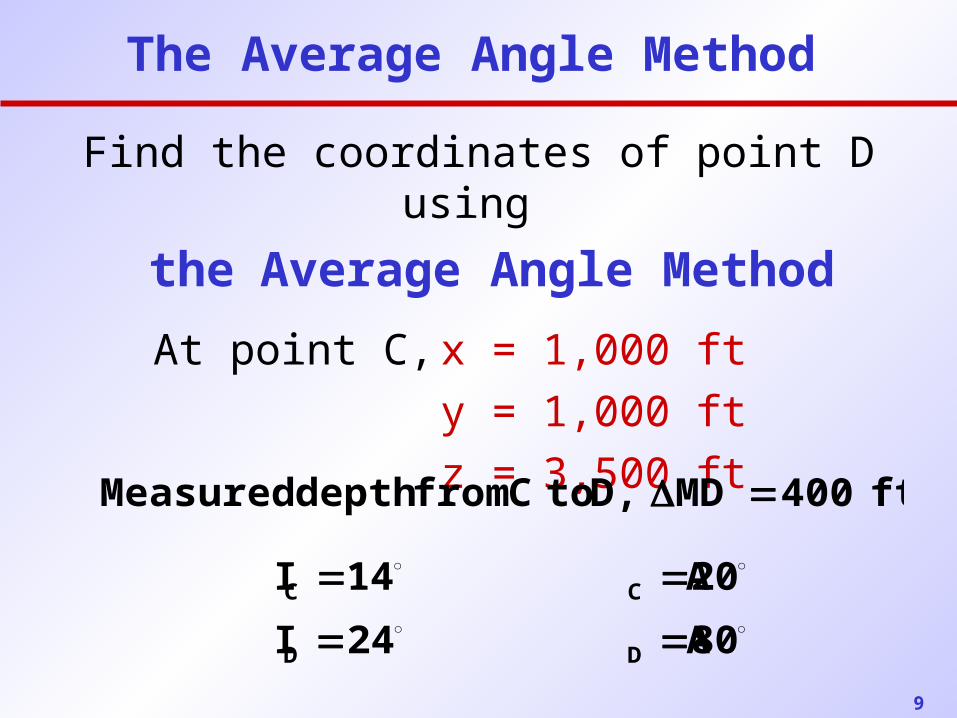
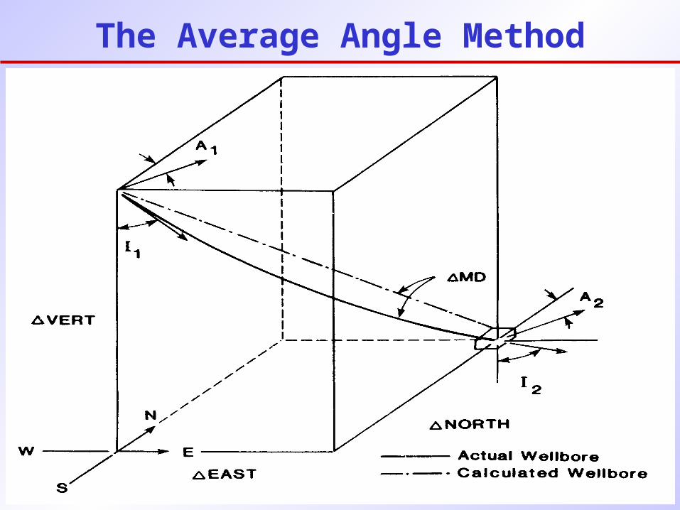
The Average Angle Method
Find the coordinates of point D using
the Average Angle Method
At point C, x = 1,000 ft
y = 1,000 ft
z = 3,500 ft
80 A 24I
20 A 14I
DD
CC
ft 400MD D, to C from depth Measured
10
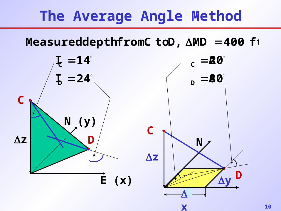
The Average Angle Method
80 A 24I
20 A 14I
ft 400MD D, to C from depth Measured
DD
CC
z
E (x)
N (y)
C
D
zN
D
C
yx
11
The Average Angle Method
12
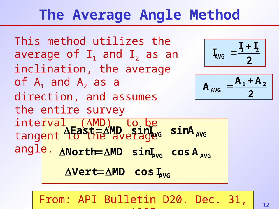
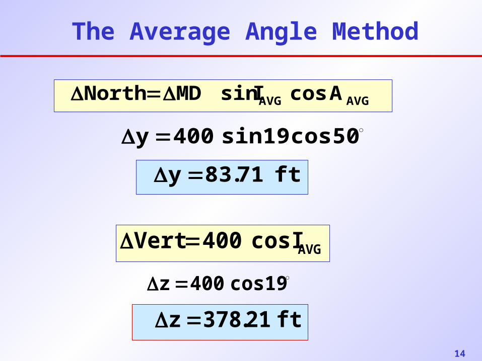
The Average Angle Method
This method utilizes the average of I1 and I2 as an inclination, the average of A1 and A2 as a direction, and assumes the entire survey interval (MD) to be tangent to the average angle.
From: API Bulletin D20. Dec. 31, 1985
2
III 21AVG
AVGAVG AsinIsinMDEast
AVGIcosMDVert
2
AAA 21
AVG
AVGAVG AcosIsinMDNorth
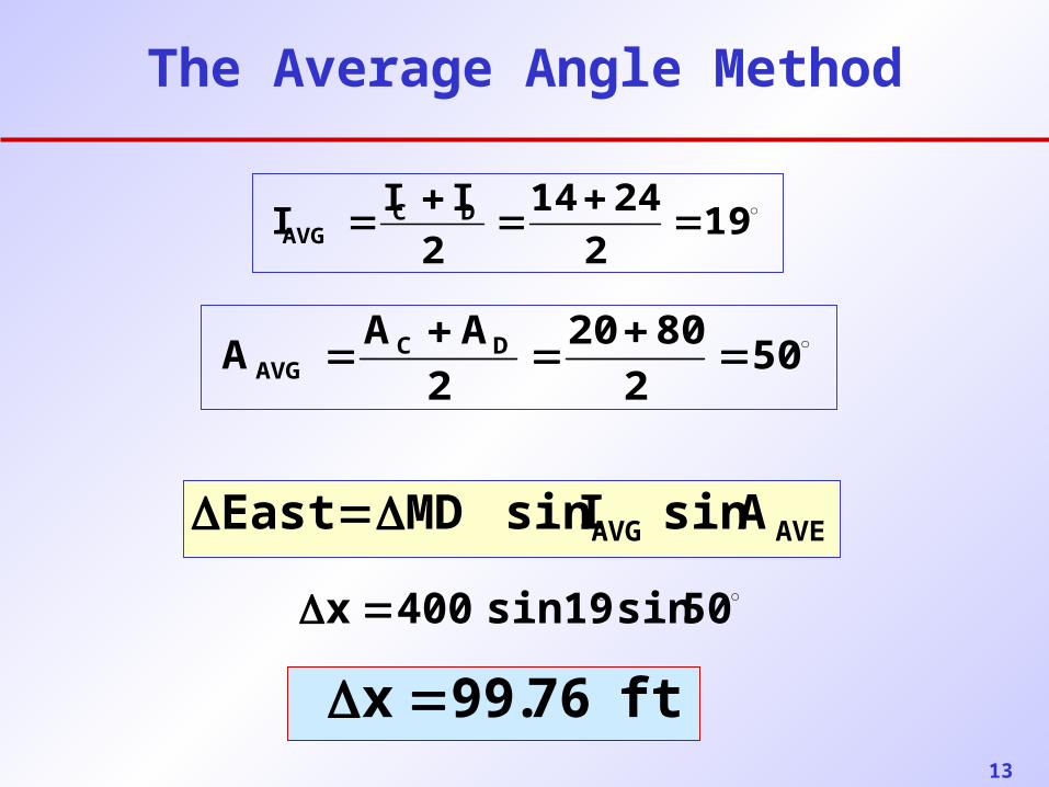
13
192
2414
2
III DCAVG
The Average Angle Method
502
8020
2
AAA DC
AVG
AVEAVG AsinIsinMDEast
50sinsin19400x
ft76.99x
14
The Average Angle Method
AVGIcos400Vert cos19400z
AVGAVG AcosIsinMDNorth
ft 71.83y
50cossin19400y
ft21.378z
15
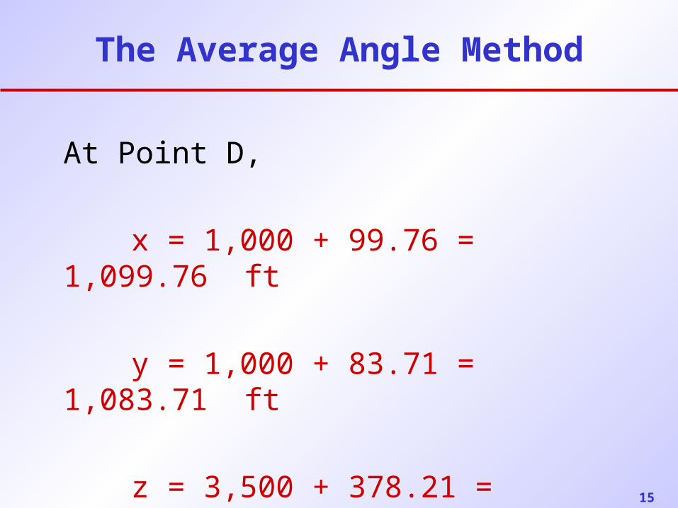
The Average Angle Method
At Point D,
x = 1,000 + 99.76 = 1,099.76 ft
y = 1,000 + 83.71 = 1,083.71 ft
z = 3,500 + 378.21 = 3,878.21 ft
16
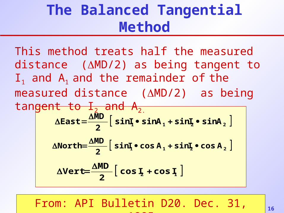
The Balanced Tangential Method
This method treats half the measured distance (MD/2) as being tangent to I1 and A1 and the remainder of the measured distance (MD/2) as being tangent to I2 and A2.
From: API Bulletin D20. Dec. 31, 1985
2211 AsinIsinAsinIsin2
MDEast
2211 AcosIsinAcosIsin2
MDNorth
12 IcosIcos2
MDVert
17
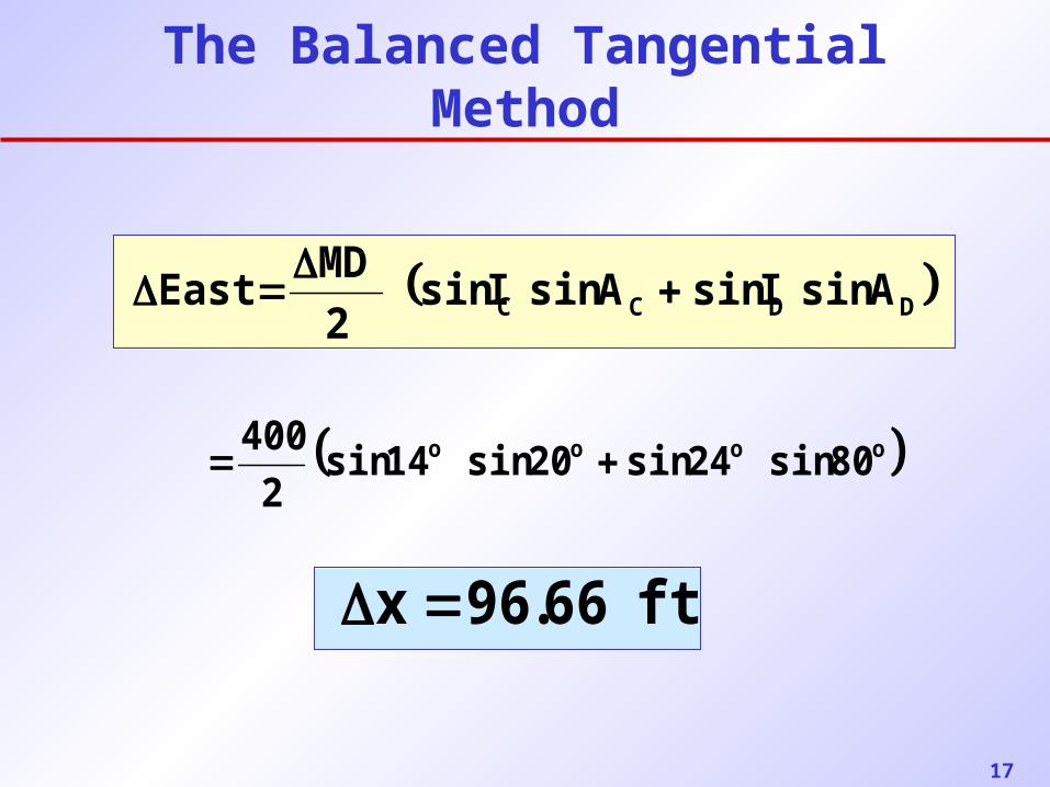
The Balanced Tangential Method
DDCC AsinIsinAsinIsin2
MDEast
oooo 80sin24sin20sin14sin2
400
ft66.96x
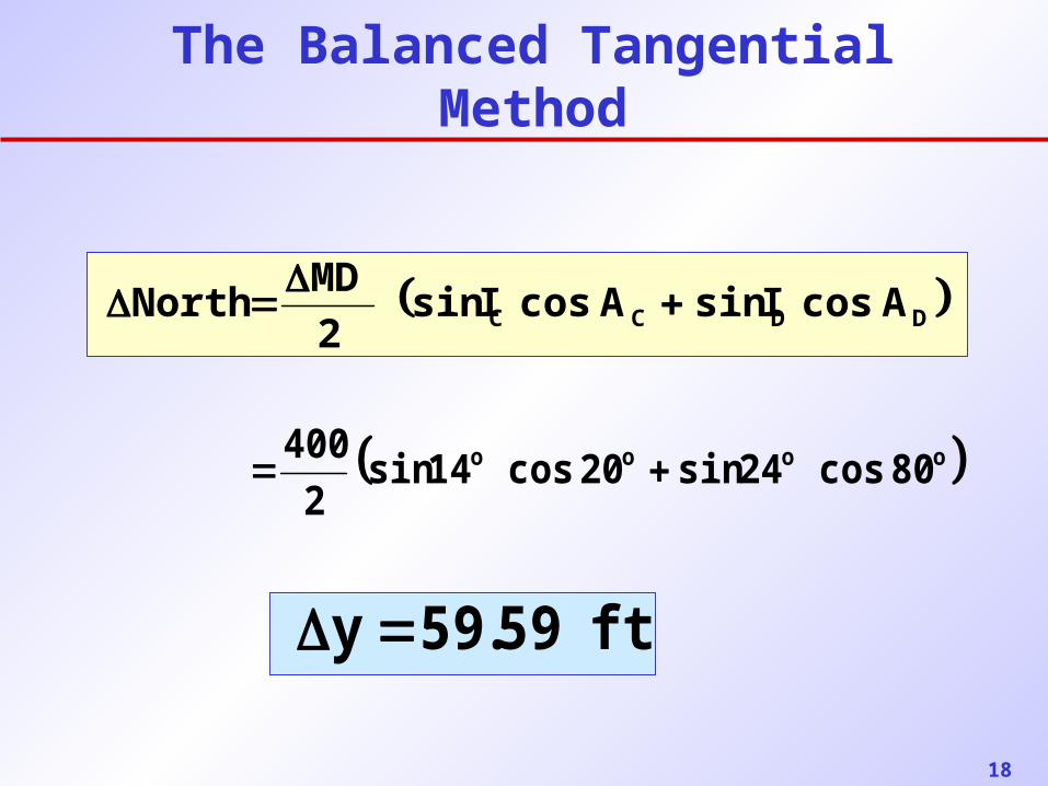
18
The Balanced Tangential Method
DDCC AcosIsinAcosIsin2
MDNorth
oooo 80cos24sin20cos14sin2
400
ft59.59y
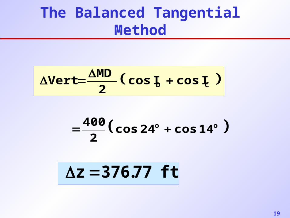
19
The Balanced Tangential Method
CD IcosIcos2
MDVert
oo 14cos24cos2
400
ft77.376z
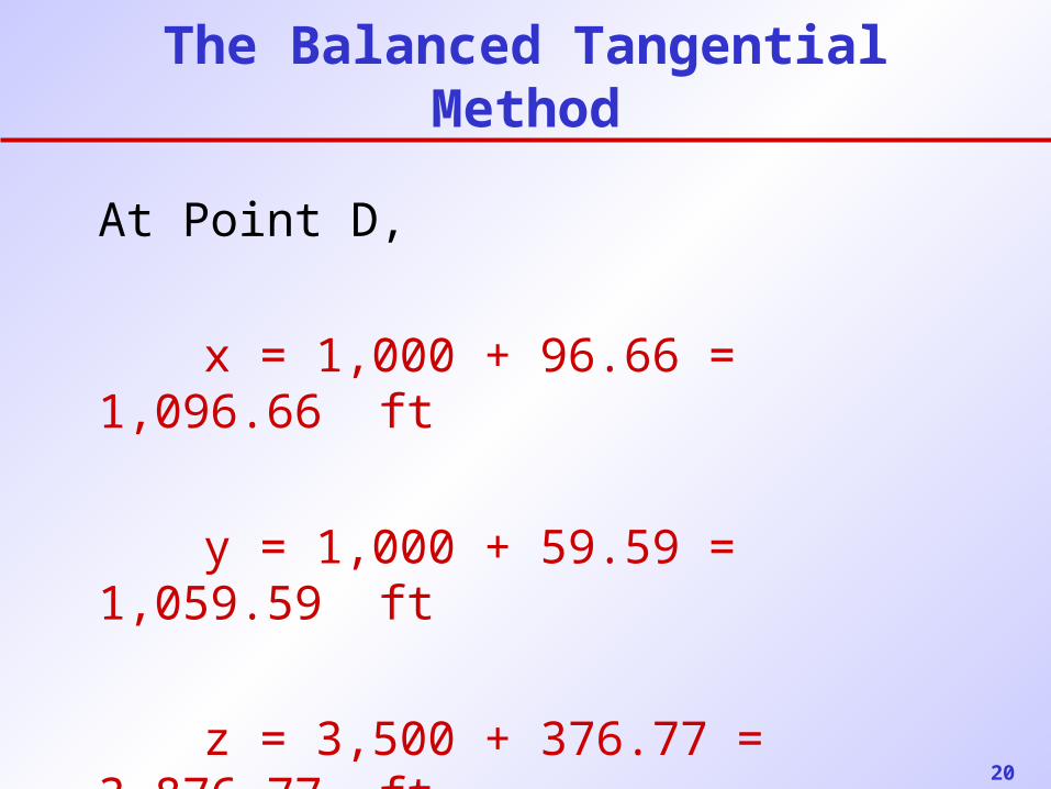
20
The Balanced Tangential Method
At Point D,
x = 1,000 + 96.66 = 1,096.66 ft
y = 1,000 + 59.59 = 1,059.59 ft
z = 3,500 + 376.77 = 3,876.77 ft
21
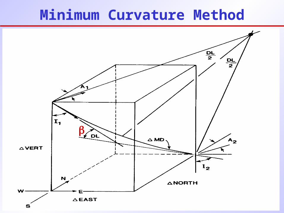
Minimum Curvature Method
22
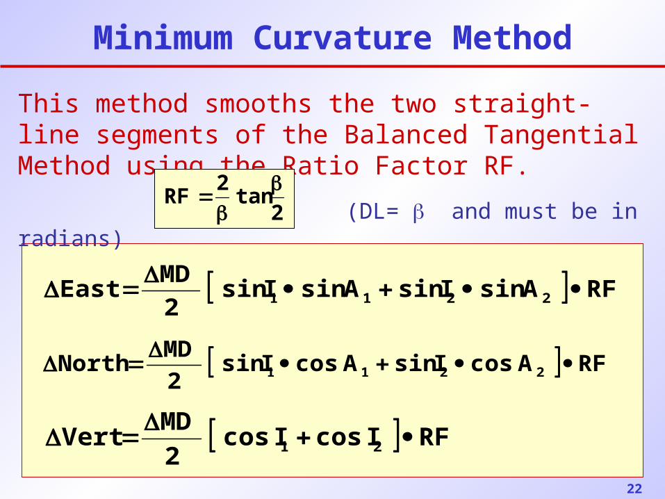
Minimum Curvature Method
This method smooths the two straight-line segments of the Balanced Tangential Method using the Ratio Factor RF.
(DL= and must be in radians)2tan
2RF
RFAcosIsinAcosIsin2
MDNorth 2211
RFAsinIsinAsinIsin2
MDEast 2211
RFIcosIcos2
MDVert 21
23
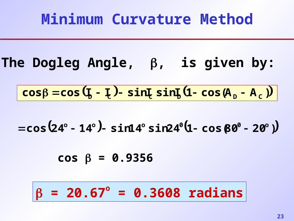
Minimum Curvature Method
)AAcos(1IsinIsinIIcoscos CDDCCD
)2080cos(124sin14sin1424cos o00ooo
cos = 0.9356
= 20.67o = 0.3608 radians
The Dogleg Angle, , is given by:
24
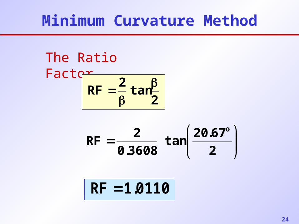
Minimum Curvature Method
The Ratio Factor,
2tan
2RF
2
67.20tan
3608.0
2RF
o
0110.1RF
25
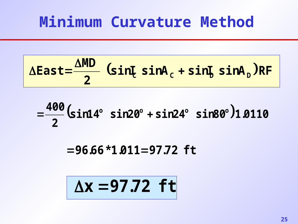
Minimum Curvature Method
RFAsinIsinAsinIsin2
MDEast DDCC
0110.180sin24sin20sin14sin2
400 oooo
ft72.97x
ft72.97011.1*66.96
26
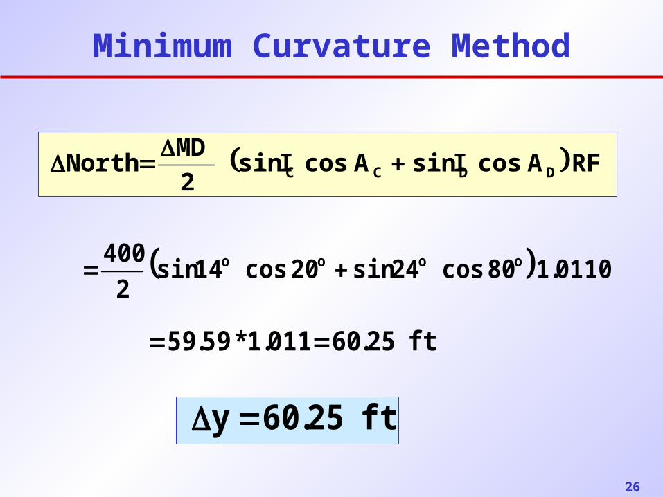
Minimum Curvature Method
RFAcosIsinAcosIsin2
MDNorth DDCC
ft25.60y
ft25.60011.1*59.59
0110.180cos24sin20cos14sin2
400 oooo
27
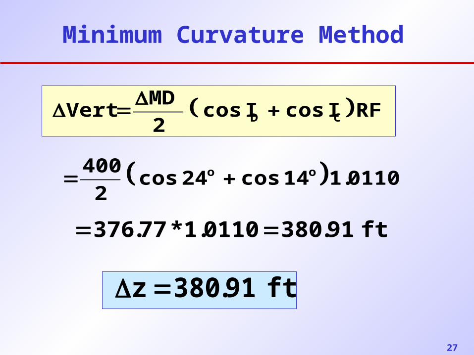
Minimum Curvature Method
RFIcosIcos2
MDVert CD
0110.114cos24cos2
400 oo
ft91.380z
ft91.3800110.1*77.376
28
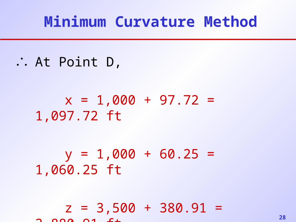
Minimum Curvature Method
At Point D,
x = 1,000 + 97.72 = 1,097.72 ft
y = 1,000 + 60.25 = 1,060.25 ft
z = 3,500 + 380.91 = 3,880.91 ft
29
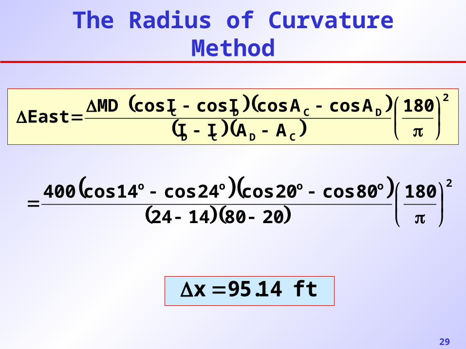
The Radius of Curvature Method
2
CDCD
DCDC 180
AAII
AcosAcosIcosIcosMDEast
2oooo 180
20801424
80cos20cos24cos14cos400
ft 14.59 x
30
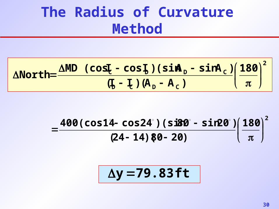
The Radius of Curvature Method
2
CDCD
CDDC 180
)AA()II(
)AsinA(sin)IcosI(cosMDNorth
2180
)2080)(1424(
)20sin80)(sin24cos400(cos14
ft 79.83 y
31
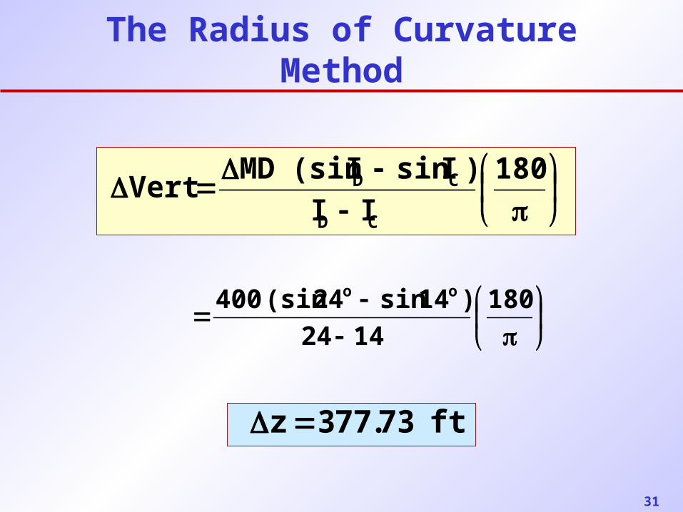
The Radius of Curvature Method
180
II
)IsinI(sinMDVert
CD
CD
ft 73.773 z
180
1424
)14sin24(sin400 oo
32
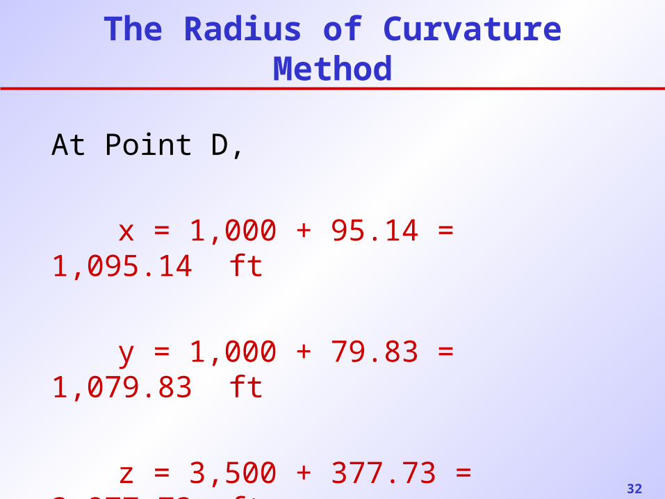
The Radius of Curvature Method
At Point D,
x = 1,000 + 95.14 = 1,095.14 ft
y = 1,000 + 79.83 = 1,079.83 ft
z = 3,500 + 377.73 = 3,877.73 ft
33
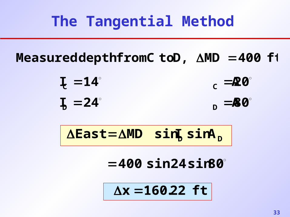
The Tangential Method
ft 400MD D, to C from depth Measured
80 A 24I
20 A 14I
DD
CC
80sinsin24400
DD AsinIsinMDEast
ft 22.160x
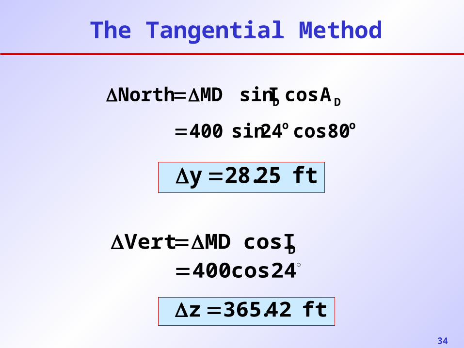
34
The Tangential Method
DIcosMDVert 24cos400
ft 42.365z
DD AcosIsinMDNorth
ft 25.28y
oo 80cos24sin400
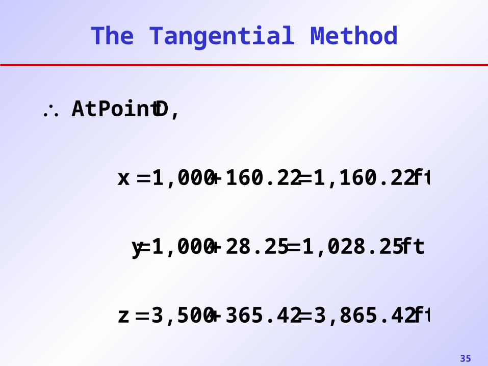
35
The Tangential Method
ft 3,865.42365.423,500z
ft 1,028.2528.251,000 y
ft 1,160.22160.221,000x
D,Point At
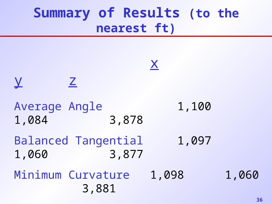
36
Summary of Results (to the nearest ft)
x y z
Average Angle 1,100 1,084 3,878
Balanced Tangential 1,097 1,060 3,877
Minimum Curvature 1,098 1,060 3,881
Radius of Curvature 1,095 1,080 3,878
Tangential Method 1,160 1,028 3,865
37
38
39
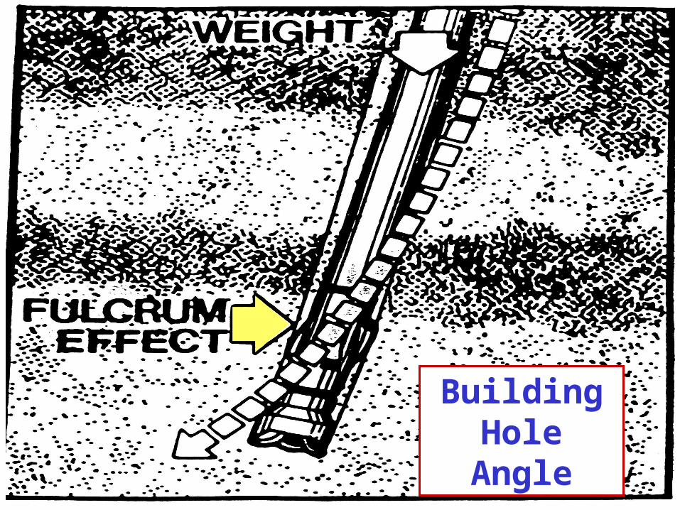
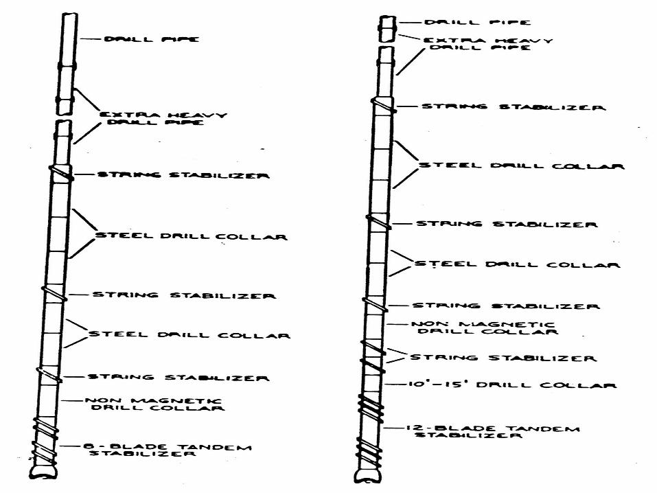
Building Hole Angle
40
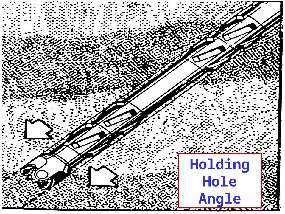
Holding Hole Angle
41
42
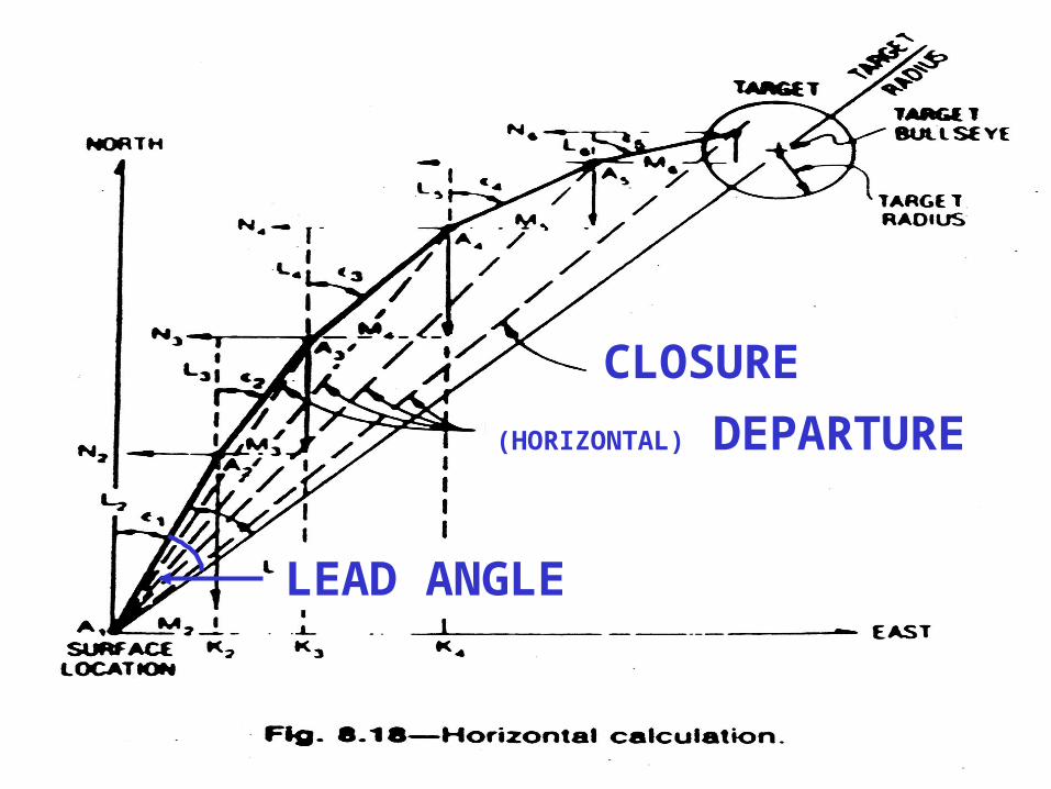
CLOSURE
LEAD ANGLE
(HORIZONTAL) DEPARTURE
43
44
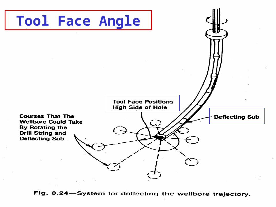
Tool Face Angle


