50
1 PETE 411 Well Drilling Lesson 8 Rolling Cutter Bits
| Date post: | 15-Dec-2015 |
| Category: |
Documents |
| Upload: | keegan-blazier |
| View: | 271 times |
| Download: | 22 times |
1
PETE 411Well Drilling
Lesson 8
Rolling Cutter Bits

2
Notice
Some seniors have not submitted their
"Student Internship Report". PETE 300.
Look for the list.
The requirement is on the web. See
department homepage
3
Lesson 8 - Bits cont’d
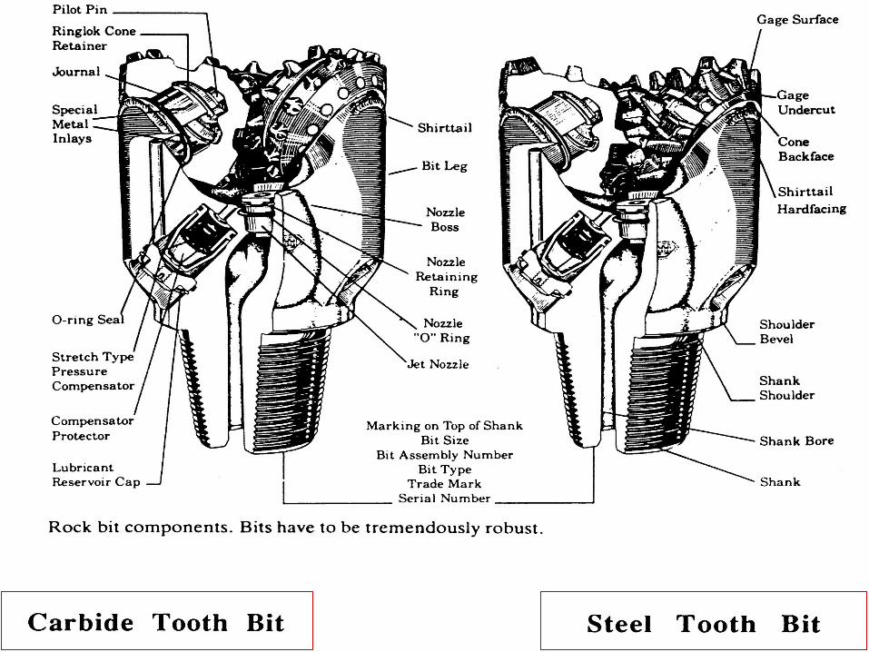
Rolling Cutter Bits• Steel Tooth (milled tooth)• Carbide Tooth (tungsten carbide insert)
Grading of Worn Bits
Bit Performance
Buoyancy
4
Read:
Applied Drilling Engineering, Ch.5 (bits)
HW #4: ADE 1.18. 1.19, 1.24
Due Monday, Sept. 23, 2002
5
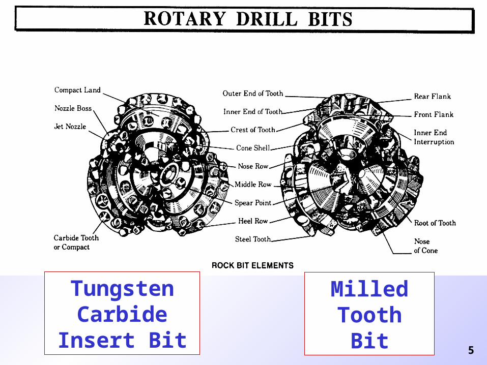
Tungsten Carbide Insert
Bit
MilledTooth
Bit
6
7
Rotary Drill BitsRoller Cutter Bits - rock bits
First rock bit introduced in 1909 by
Howard Hughes
• 2 - cone bit
• Not self-cleaning
8
Rotary Drill Bits
• Improvements
• 3 - cone bit (straighter hole)
• Intermeshing teeth (better cleaning)
• Hard-facing on teeth and body
• Change from water courses to jets
• Tungsten carbide inserts
• Sealed bearings
• Journal bearings
9
Rotary Drill Bits
• Advantages
• For any type of formation there is a suitable design of rock bit
• Can handle changes in formation
• Acceptable life and drilling rate
• Reasonable cost
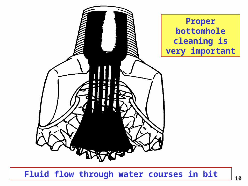
10
Fluid flow through water courses in bit
Proper bottomhole
cleaning is very important
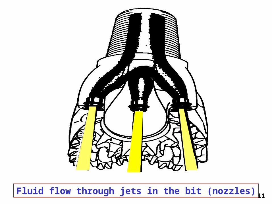
11
Fluid flow through jets in the bit (nozzles)
12
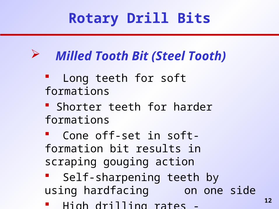
Rotary Drill Bits
Milled Tooth Bit (Steel Tooth)
Long teeth for soft formations Shorter teeth for harder formations Cone off-set in soft-formation bit results in
scraping gouging action Self-sharpening teeth by using hardfacing on one side High drilling rates - especially in softer
rocks
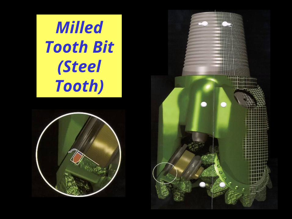
13
Milled Tooth Bit
(Steel Tooth)
14
Rotary Bits
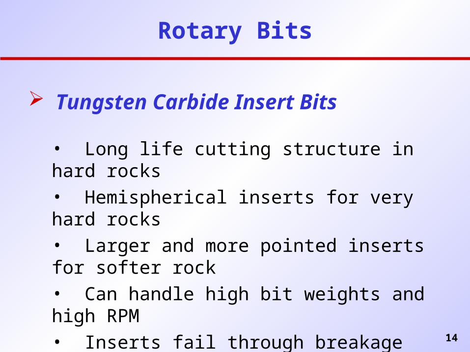
Tungsten Carbide Insert Bits
• Long life cutting structure in hard rocks• Hemispherical inserts for very hard rocks• Larger and more pointed inserts for softer rock• Can handle high bit weights and high RPM• Inserts fail through breakage rather than wear
(Tungsten carbide is a very hard, brittle material)
15
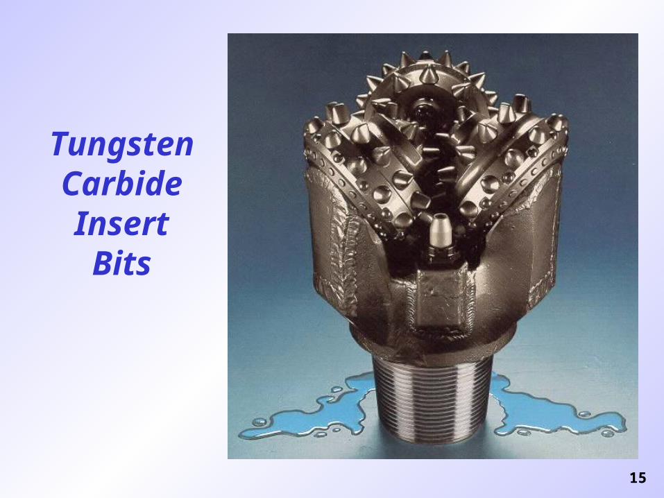
Tungsten Carbide Insert Bits
16
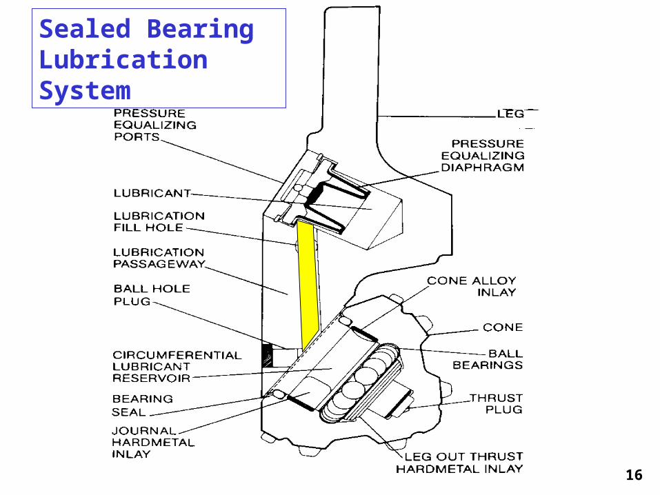
Sealed Bearing Lubrication System
17
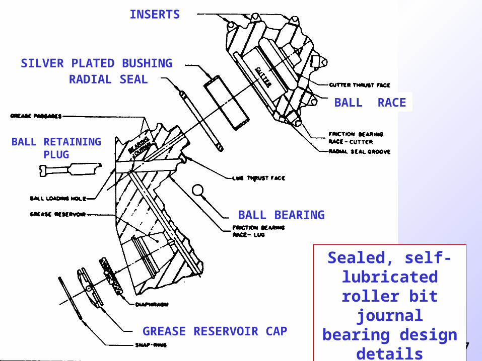
Sealed, self-lubricated roller bit
journal bearing design details
INSERTS
SILVER PLATED BUSHINGRADIAL SEAL
BALL BEARING
GREASE RESERVOIR CAP
BALL RETAINING PLUG
BALL RACE
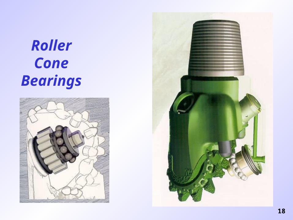
18
Roller Cone
Bearings
19
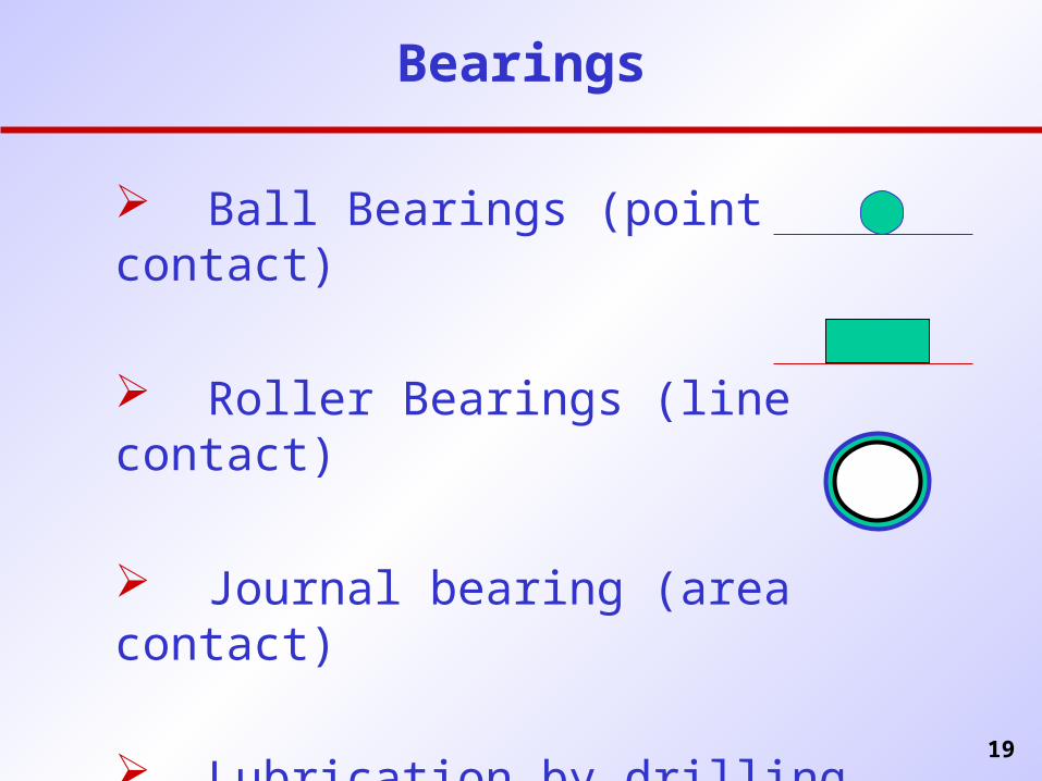
Bearings
Ball Bearings (point contact)
Roller Bearings (line contact)
Journal bearing (area contact)
Lubrication by drilling fluid . . . or . . .
20
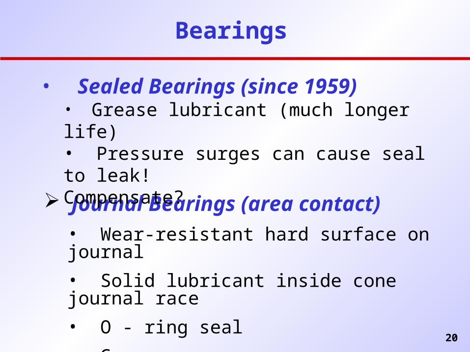
Bearings
Journal Bearings (area contact)• Wear-resistant hard surface on journal
• Solid lubricant inside cone journal race
• O - ring seal
• Grease
• Sealed Bearings (since 1959)• Grease lubricant (much longer life)• Pressure surges can cause seal to leak!
Compensate?
21
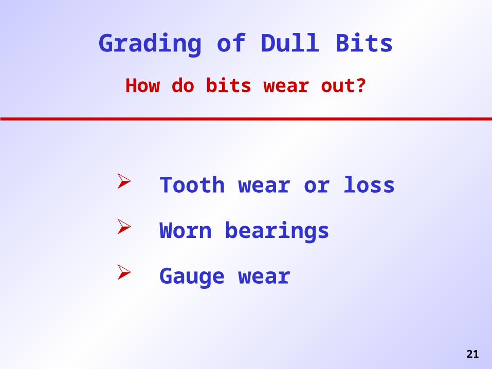
Grading of Dull Bits
How do bits wear out?
Tooth wear or loss
Worn bearings
Gauge wear
22
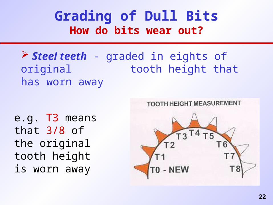
Grading of Dull BitsHow do bits wear out?
Steel teeth - graded in eights of original tooth height that has worn away
e.g. T3 means that 3/8 of the original tooth height is worn away
23
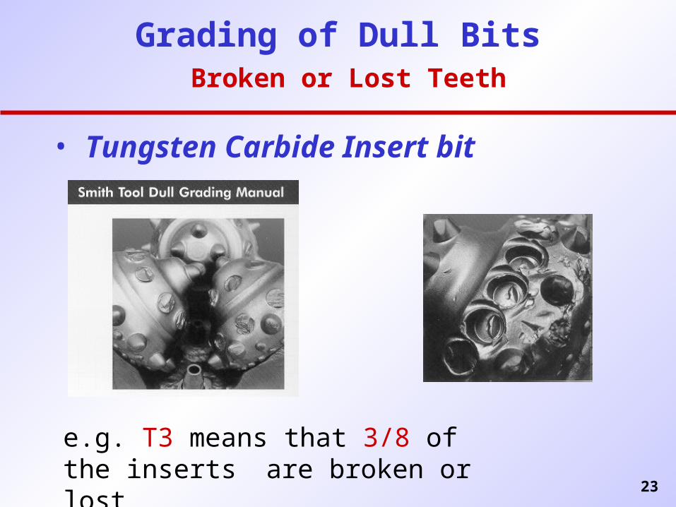
Grading of Dull Bits Broken or Lost Teeth
• Tungsten Carbide Insert bit
e.g. T3 means that 3/8 of the inserts are broken or lost
24
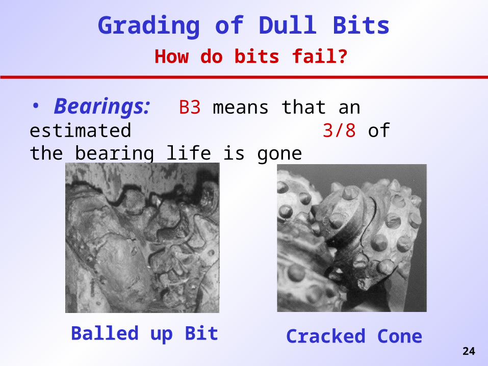
Grading of Dull Bits How do bits fail?
• Bearings: B3 means that an estimated 3/8 of the bearing life is gone
Balled up Bit Cracked Cone
25
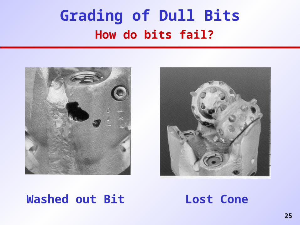
Grading of Dull Bits How do bits fail?
Washed out Bit Lost Cone
26
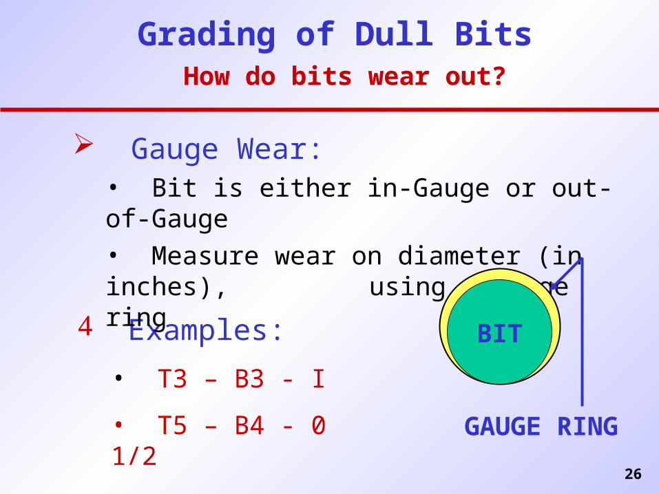
Grading of Dull Bits How do bits wear out?
Examples:
• T3 – B3 - I
• T5 – B4 - 0 1/2
Gauge Wear:• Bit is either in-Gauge or out-of-Gauge• Measure wear on diameter (in inches),
using a gauge ring
BIT
GAUGE RING
27
IADC ROLLER CONE
BIT CLASSIFICATION
SYSTEM
28
IADC System
Operational since 1972
Provides a Method of Categorizing Roller Cone
Rock Bits
Design and Application related coding
Most Recent Revision ‘The IADC Roller Bit Classification System’
1992, IADC/SPE Drilling Conference
Paper # 23937
29
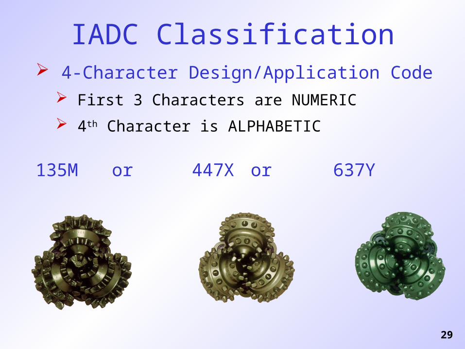
IADC Classification 4-Character Design/Application Code
First 3 Characters are NUMERIC
4th Character is ALPHABETIC
135M or 447X or 637Y
31
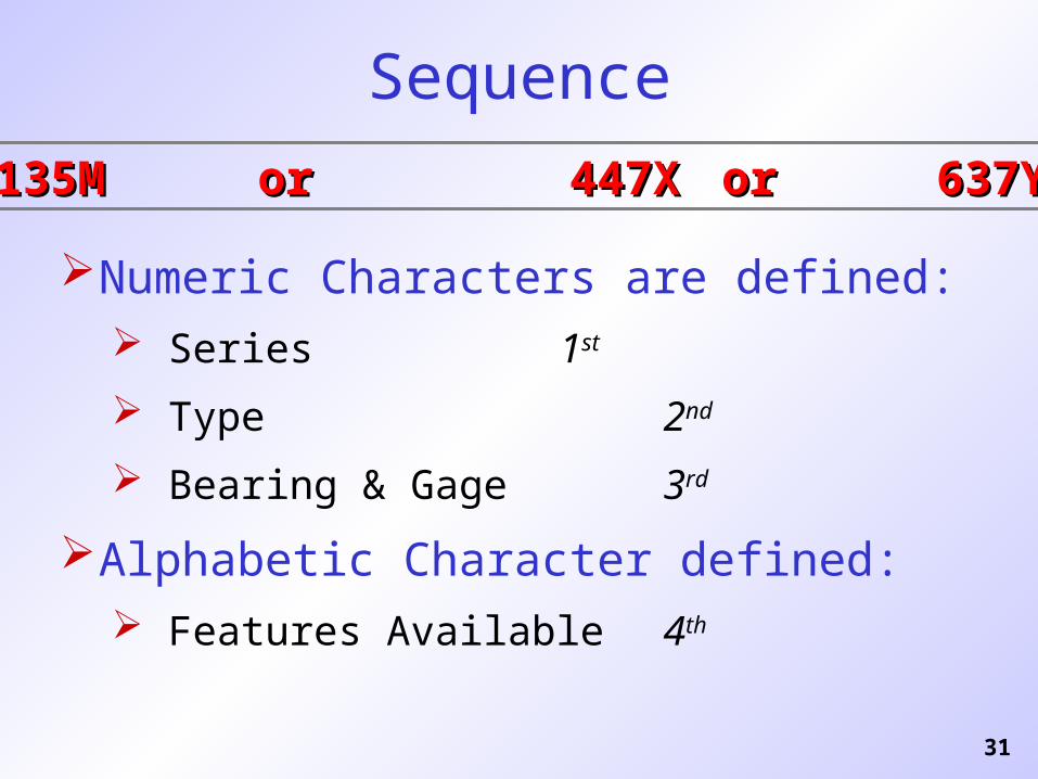
Sequence
Numeric Characters are defined: Series 1st
Type 2nd
Bearing & Gage 3rd
Alphabetic Character defined: Features Available 4th
135M135M or or 447X 447X oror 637Y 637Y
32
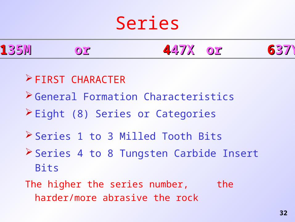
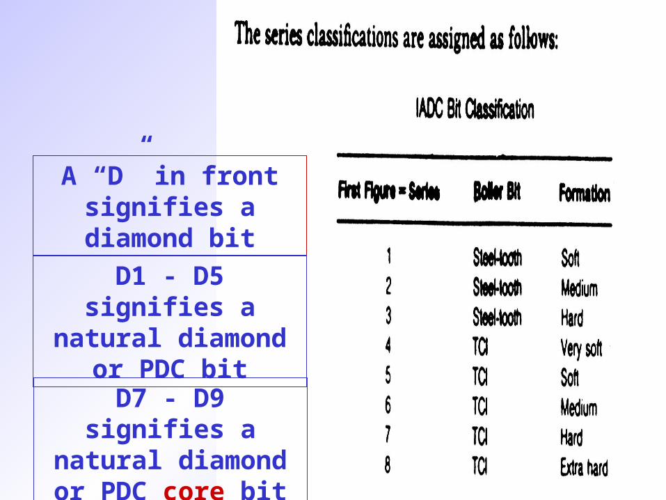
Series
FIRST CHARACTER
General Formation Characteristics
Eight (8) Series or Categories
Series 1 to 3 Milled Tooth Bits
Series 4 to 8 Tungsten Carbide Insert Bits
The higher the series number,
the harder/more abrasive the rock
1135M35M or or 4447X47X oror 6637Y37Y
33
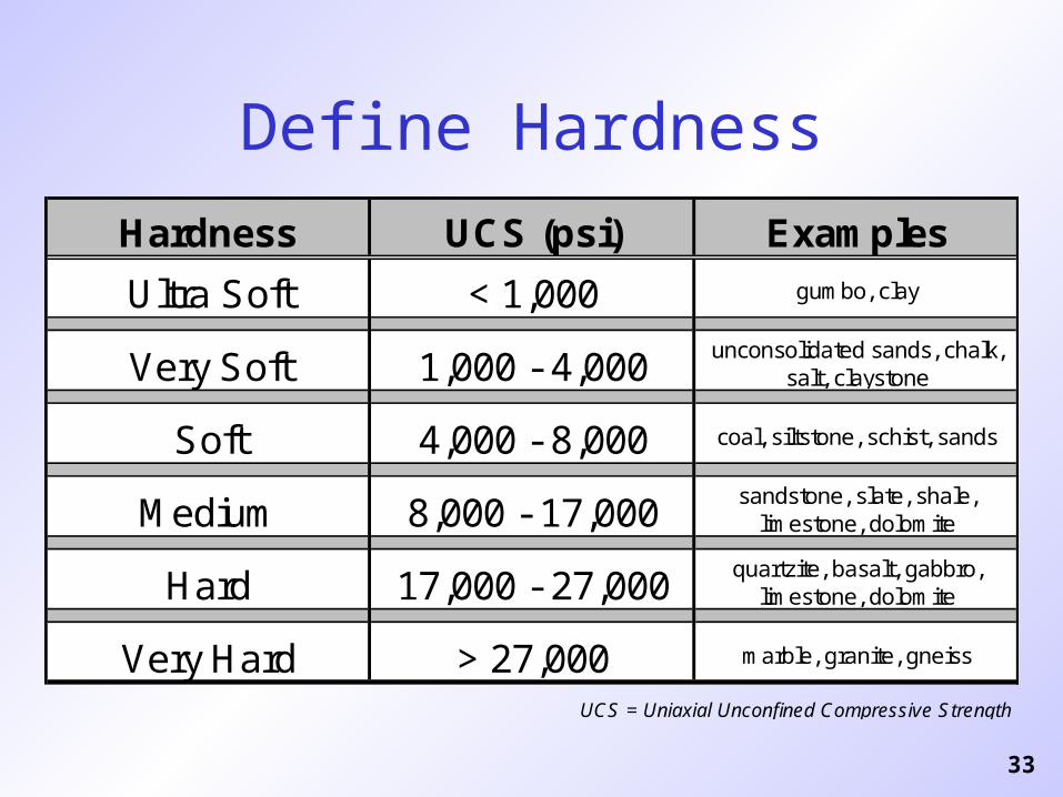
Define Hardness
Hardness UCS (psi) Examples
Ultra Soft < 1,000 gumbo, clay
Very Soft 1,000 - 4,000 unconsolidated sands, chalk, salt, claystone
Soft 4,000 - 8,000 coal, siltstone, schist, sands
Medium 8,000 - 17,000 sandstone, slate, shale, limestone, dolomite
Hard 17,000 - 27,000 quartzite, basalt, gabbro, limestone, dolomite
Very Hard > 27,000 marble, granite, gneiss
UCS = Uniaxial Unconfined Compressive Strength
34
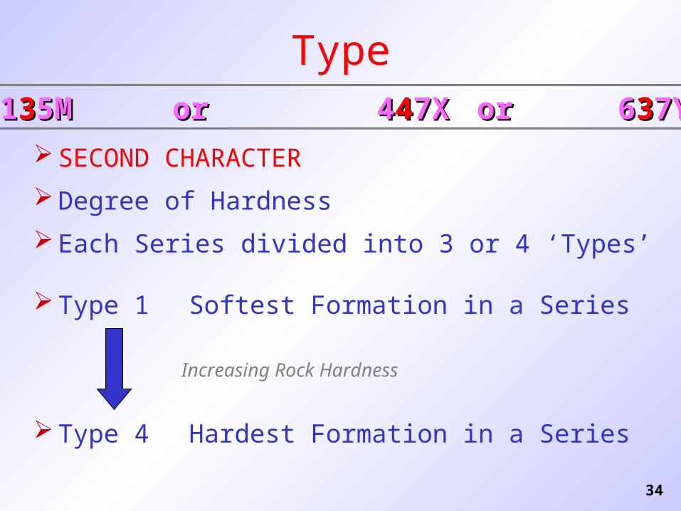
Type
SECOND CHARACTER
Degree of Hardness
Each Series divided into 3 or 4 ‘Types’
Type 1 Softest Formation in a Series
Type 4 Hardest Formation in a Series
Increasing Rock Hardness
11335M5M or or 4 4447X7X oror 6 6337Y7Y
35
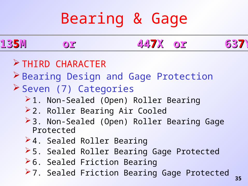
Bearing & Gage
THIRD CHARACTER Bearing Design and Gage Protection Seven (7) Categories
1. Non-Sealed (Open) Roller Bearing2. Roller Bearing Air Cooled3. Non-Sealed (Open) Roller Bearing Gage Protected4. Sealed Roller Bearing5. Sealed Roller Bearing Gage Protected6. Sealed Friction Bearing7. Sealed Friction Bearing Gage Protected
131355MM or or 44 4477XX oror 63 6377YY

36
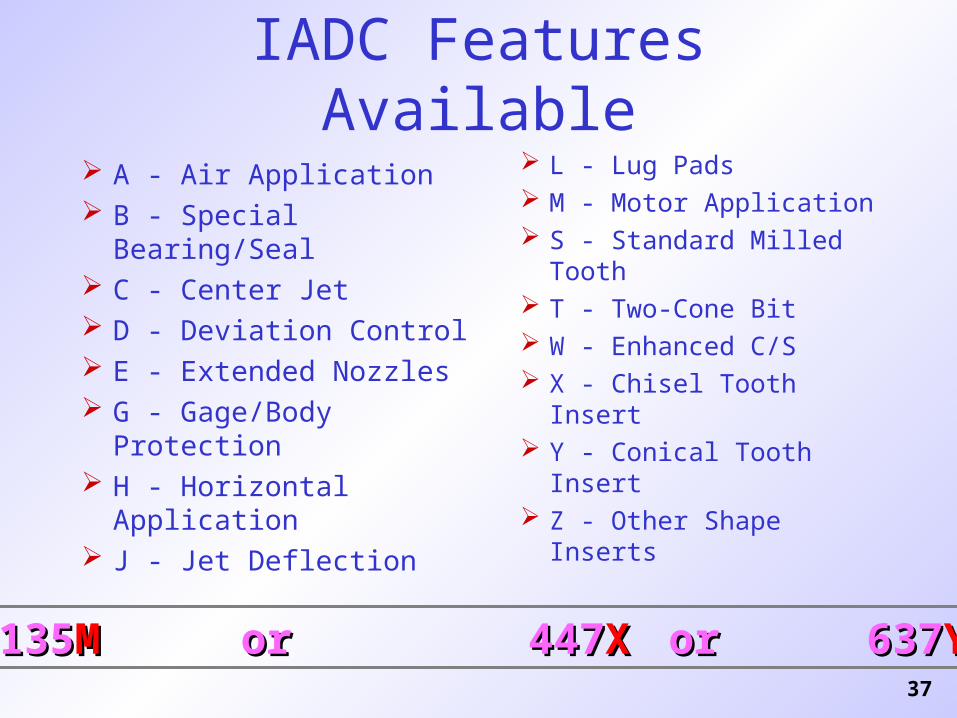
Features Available
FOURTH CHARACTER
Features Available (Optional)
Sixteen (16) Alphabetic Characters
Most Significant Feature Listed(i.e. only one alphabetic character should be selected).
135135MM or or 447 447XX oror 637 637YY
37
IADC Features Available
A - Air Application B - Special Bearing/Seal C - Center Jet D - Deviation Control E - Extended Nozzles G - Gage/Body Protection H - Horizontal Application J - Jet Deflection
L - Lug Pads M - Motor Application S - Standard Milled
Tooth T - Two-Cone Bit W - Enhanced C/S X - Chisel Tooth Insert Y - Conical Tooth Insert Z - Other Shape Inserts
135135MM or or 447 447XX oror 637 637YY

38
Categorization - Summary
Convenient Categorization System
Design and Application Code
Know its Limitations
Use Carefully in Application DecisionsConsider other sources: offset bit records;
dull grading; performance analysis.
39
40
A “D” in front signifies a diamond bit
D1 - D5 signifies a natural diamond or
PDC bit
D7 - D9 signifies a natural diamond or
PDC core bit
41
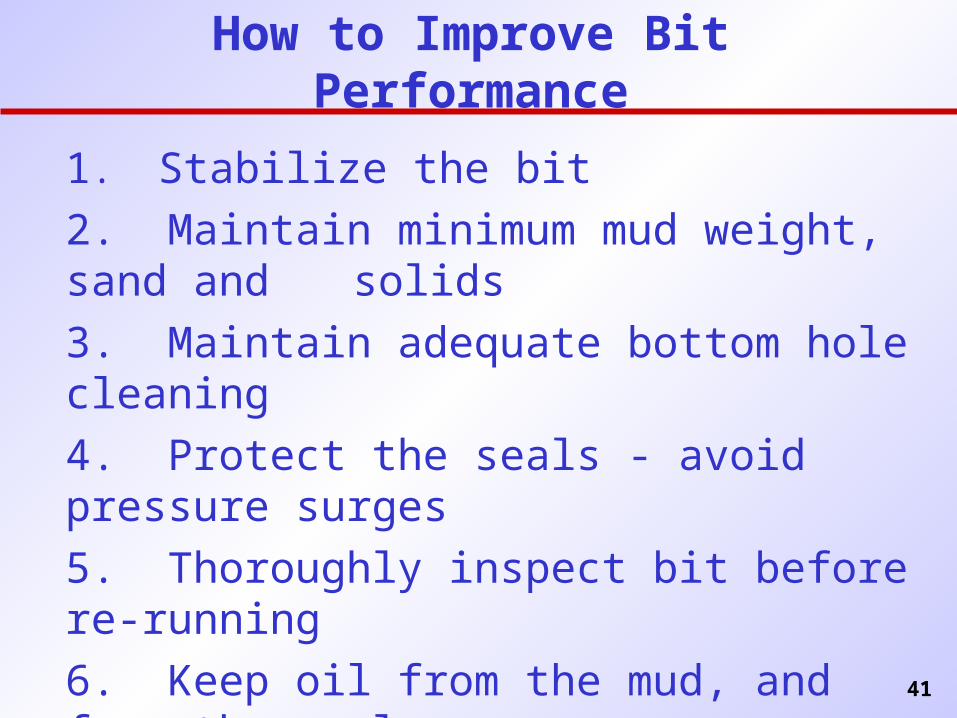
How to Improve Bit Performance
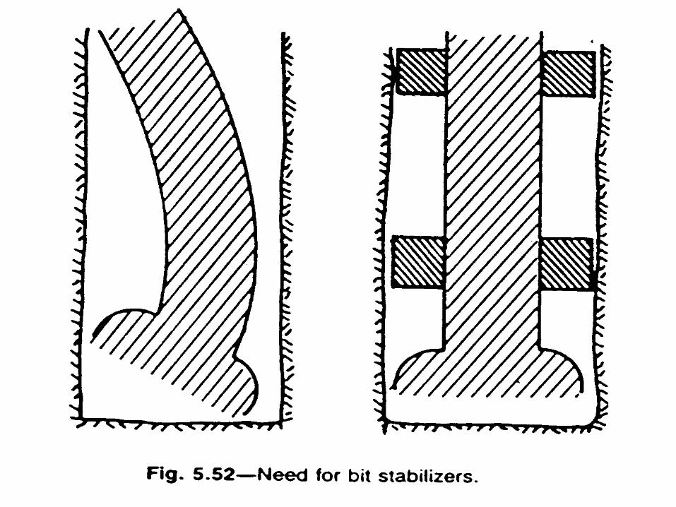
1. Stabilize the bit
2. Maintain minimum mud weight, sand and solids
3. Maintain adequate bottom hole cleaning
4. Protect the seals - avoid pressure surges
5. Thoroughly inspect bit before re-running
6. Keep oil from the mud, and from the seals
7. Follow manufacturers recommendations
(e.g. 6,000 lb/in of diameter and 40-60 RPM)
42
43
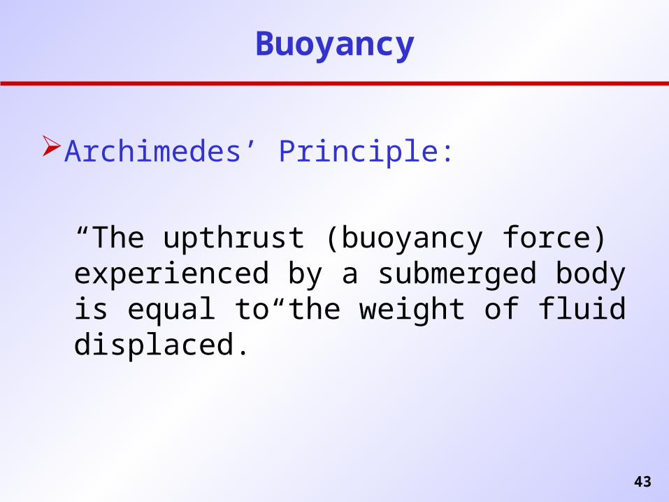
Buoyancy
Archimedes’ Principle:
“The upthrust (buoyancy force) experienced by a submerged body is equal to the weight of fluid displaced.”
44
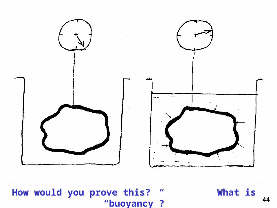
How would you prove this? What is “buoyancy”?
45
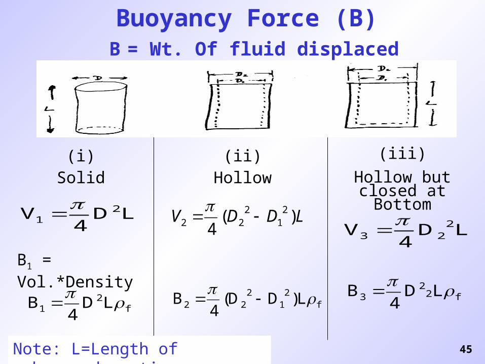
Buoyancy Force (B) B = Wt. Of fluid displaced
(i)Solid
(ii)Hollow
(iii)
Hollow but closed at Bottom
LD4
V 21
B1 = Vol.*Density
f2
1 LD4
B f
21
222 L)DD(
4B
LD4
V 223
f22
3 LD4
B
LDDV )(4
21
222
Note: L=Length of submerged section
46
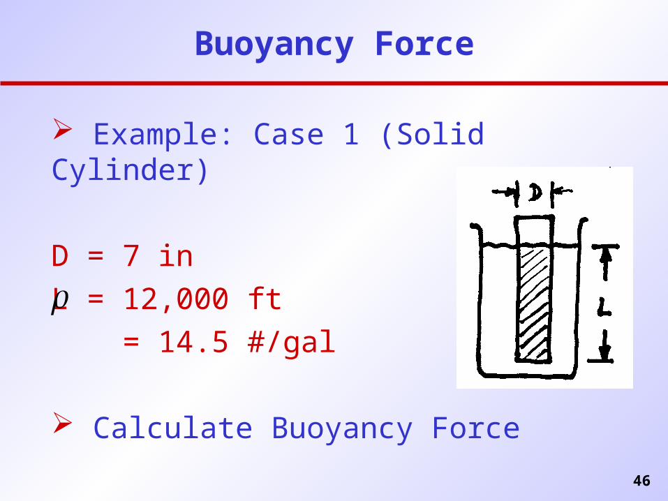
Buoyancy Force
Example: Case 1 (Solid Cylinder)
D = 7 in
L = 12,000 ft
= 14.5 #/gal
Calculate Buoyancy Force
47
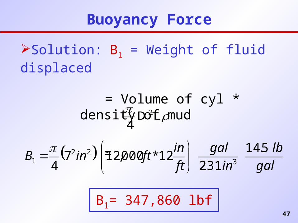
Buoyancy Force
Solution: B1 = Weight of fluid displaced
= Volume of cyl * density of mud
= LD
42
gal
lb
in
gal
ft
inftinB
5.14
23112*000,127
4 322
1
B1= 347,860 lbf
48
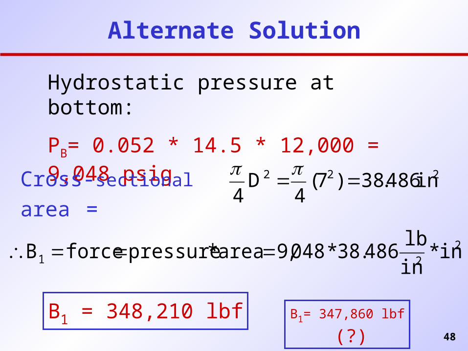
Alternate Solution
Hydrostatic pressure at bottom:
PB= 0.052 * 14.5 * 12,000 = 9,048 psig
Cross-sectional area = 222 in486.38)7(
4D
4
221 in*
in
lb486.38*048,9area*pressureforceB
B1 = 348,210 lbf B1= 347,860 lbf (?)
49
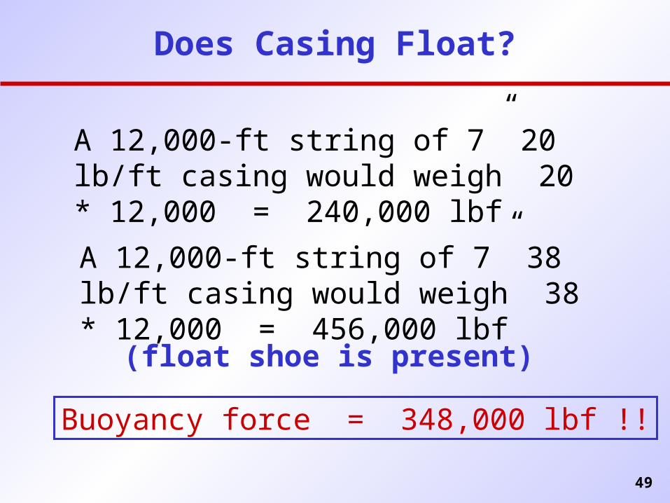
Does Casing Float?
A 12,000-ft string of 7” 20 lb/ft casing would weigh 20 * 12,000 = 240,000 lbf
A 12,000-ft string of 7” 38 lb/ft casing would weigh 38 * 12,000 = 456,000 lbf
Buoyancy force = 348,000 lbf !!
(float shoe is present)
50
51
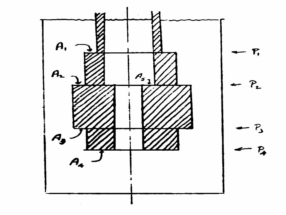
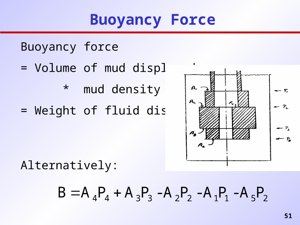
Buoyancy force
= Volume of mud displaced
* mud density
= Weight of fluid displaced
Alternatively:
Buoyancy Force
2511223344 PA - PA - PA - PA PA B


