PFR for expansion by adding Beneficiation Plant, Sponge Iron Plant, Induction Furnace, Captive Power Plant and Rolling Mill the Existing Sponge Iron Plant of M/s. Bhadrashree Steel & Power Ltd., Koppal. 1 Prepared by: METAMRPHOSIS Project Consultants Pvt. Ltd., Bengaluru 1 CHAPTER – 1 EXECUTIVE SUMMARY M/s. Bhadrashree Steel and Power Ltd., is a Public Limited Company, which is incorporated during 24 th November 2004. Corporate office situated in “Ananda Nilaya”, Jain Colony, Hosapete. Based on the steel demand, Company proposes to expand the project by adding Beneficiation Plant, Sponge Iron Plant, Induction Furnace, Captive Power Plant and Rolling Mill in the Existing Sponge Iron Plant. The existing capacity of plant is 200 TPD Sponge Iron Unit. The proposal was made for the expansion from 200 TPD Sponge Iron Unit to Mini Integrated Steel plant. Terms of Reference was issued on 12/08/2010 for the following capacities. A copy of the Terms of Reference is enclosed as Annexure No – 1. Table 1.1: Capacity for which TOR issued Sr. No. Unit Capacity for which TOR issued 1 Sponge Iron plant 200 TPD 2 Captive Power Plant AFBC - 7 MW WHRB - 8 MW Total - 15 MW 3 Induction Furnace 2 x 10 T 4 Rolling Mill 60,000 TPA However, there were modifications in the capacities for which new Terms of Reference was requested. The details of expansion are as follows; Table 1.2: Proposed expansion for which Revised TOR was issued Sr. No. Unit Proposed expansion for which Revised TOR was requested 1 Sponge Iron plant 400 TPD 2 Captive Power Plant No change 3 Induction Furnace 2 x 20 T 4 Rolling Mill 90,000 TPA The proposed activity is categorized as ‘Category – A’ project as per Environmental Impact Assessment (EIA) Notification.
Transcript
PFR for expansion by adding Beneficiation Plant, Sponge Iron Plant, Induction Furnace, CaptivePower Plant and Rolling Mill the Existing Sponge Iron Plant of M/s. Bhadrashree Steel & PowerLtd., Koppal.
M/s. Bhadrashree Steel and Power Ltd., is a Public Limited Company, which isincorporated during 24th November 2004. Corporate office situated in “Ananda Nilaya”,Jain Colony, Hosapete. Based on the steel demand, Company proposes to expand theproject by adding Beneficiation Plant, Sponge Iron Plant, Induction Furnace, CaptivePower Plant and Rolling Mill in the Existing Sponge Iron Plant.The existing capacity of plant is 200 TPD Sponge Iron Unit. The proposal was made forthe expansion from 200 TPD Sponge Iron Unit to Mini Integrated Steel plant. Terms ofReference was issued on 12/08/2010 for the following capacities. A copy of the Termsof Reference is enclosed as Annexure No – 1.
Table 1.1: Capacity for which TOR issued
Sr. No. Unit Capacity for which TOR issued1 Sponge Iron plant 200 TPD2 Captive Power Plant AFBC - 7 MWWHRB - 8 MWTotal - 15 MW3 Induction Furnace 2 x 10 T4 Rolling Mill 60,000 TPAHowever, there were modifications in the capacities for which new Terms of Referencewas requested. The details of expansion are as follows;Table 1.2: Proposed expansion for which Revised TOR was issued
Sr. No. Unit Proposed expansion for whichRevised TOR was requested1 Sponge Iron plant 400 TPD2 Captive Power Plant No change3 Induction Furnace 2 x 20 T4 Rolling Mill 90,000 TPAThe proposed activity is categorized as ‘Category – A’ project as per EnvironmentalImpact Assessment (EIA) Notification.
PFR for expansion by adding Beneficiation Plant, Sponge Iron Plant, Induction Furnace, CaptivePower Plant and Rolling Mill the Existing Sponge Iron Plant of M/s. Bhadrashree Steel & PowerLtd., Koppal.
Due to the market condition and ban on iron ore mining in three Districts of Karnatakaincluding Bellary vide MoEF OM dated 05.10.2011. Proponent could not take-up theproposal.Consent to Operate (CFO) from Karnataka State Pollution Control Board for the existingsponge iron unit is renewed time to time. A copy of CFO is enclosed as Annexure No –2.
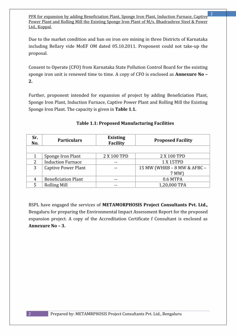
Further, proponent intended for expansion of project by adding Beneficiation Plant,Sponge Iron Plant, Induction Furnace, Captive Power Plant and Rolling Mill the ExistingSponge Iron Plant. The capacity is given in Table 1.1.
Table 1.1: Proposed Manufacturing Facilities
Sr.No. Particulars Existing
Facility Proposed Facility
1 Sponge Iron Plant 2 X 100 TPD 2 X 100 TPD2 Induction Furnace -- 1 X 15TPD3 Captive Power Plant -- 15 MW (WHRB – 8 MW & AFBC –7 MW)4 Beneficiation Plant -- 0.6 MTPA5 Rolling Mill -- 1,20,000 TPABSPL have engaged the services of METAMORPHOSIS Project Consultants Pvt. Ltd.,Bengaluru for preparing the Environmental Impact Assessment Report for the proposedexpansion project. A copy of the Accreditation Certificate f Consultant is enclosed asAnnexure No – 3.
PFR for expansion by adding Beneficiation Plant, Sponge Iron Plant, Induction Furnace, CaptivePower Plant and Rolling Mill the Existing Sponge Iron Plant of M/s. Bhadrashree Steel & PowerLtd., Koppal.
INTRODUCTION OF THE PROJECT / BACKGROUND INFORMATION
2.1 Identification of the Project and Project Proponent
2.1.1 Identification of the Project
India was the world’s third-largest steel producer in 2017. The growth in the Indiansteel sector has been driven by domestic availability of raw materials such as iron oreand cost-effective labour. Consequently, the steel sector has been a major contributor toIndia’s manufacturing output.The Indian steel industry is very modern with state-of-the-art steel mills. It has alwaysstrived for continuous modernization and up-gradation of older plants and higherenergy efficiency levels.Indian steel industries are classified into three categories such as major producers,main producers and secondary producers.M/s. Bhadrashree Steel and Power Ltd., is a Public Limited Company, which isincorporated during 24th November 2004. Corporate office situated in “Ananda Nilaya”,Jain Colony, Hosapete. Based on the steel demand, Company proposes to expand theproject by adding Beneficiation Plant, Sponge Iron Plant, Induction Furnace, CaptivePower Plant and Rolling Mill in the Existing Sponge Iron Plant.2.1.2. About Project Proponent
The promoters have rich industrial background having vivid business experience andexcellent track record. The promoters have sound financial position with sufficientliquidity to promote new ventures. They have vast business network in various field ofbusiness since long and are having good business developments along with securing allavailed limits enjoyed from various banks in an excellent manner. The strength of theirrecords shows that, they are enjoying good market reputation in the business andindustry related fields.
PFR for expansion by adding Beneficiation Plant, Sponge Iron Plant, Induction Furnace, CaptivePower Plant and Rolling Mill the Existing Sponge Iron Plant of M/s. Bhadrashree Steel & PowerLtd., Koppal.
The promoters / Directors of the company are as under:
1. Mr. Mukesh Goel2. Mr. Amit Agarwal3. Mr. Rashid Iqbal4. Mr. Piyush GoelA brief profile of the directors is given below;
Mr. Mukesh Goel is a veteran player in Steel manufacturing, a graduate and a highlyexperienced businessman, based in Muzaffarnagar (UP.). He is Director of M/s. ConeCraft Paper Private Limited. He is also operating an Induction Furnace (capacity - 26000TPA) in the name of Uttarayan Steel Private Limited. As he was engaged inmanufacturing activities, he is well versed with the details of manufacturing andhandling large projects. His family is in Steel business since last 25 years. They haveinstalled first Induction Furnace in Muzaffarnagar (U.P.) in 1982 in the name of M/s.Vaishnav Steels Private Limited and he is the authorized signatory.Mr. Amit Agarwal, is a well-known name in the Iron and Steel market of Hyderabadand He is into the business of iron ore & steel products for over 20 years through hisconcerns viz. 1) M/s. Aashirwad Mines & Minerals & 2) Adarsh Enterprises, engaged inTrading of Iron Ore with turnover of Rs. 800 lacs. He is having excellent experience inthe field of Iron & Steel and is well versed in negotiating about procurement of materialsetc.Mohd. Rashid Iqbal, s/o Izhar Hussain is 48 years old. He is proprietor in N.S.Enterprises, deals in manufacturing & Trading of Electronic goods. He is PromoterDirector in N.S. Infratech Pvt. Ltd., deals in development of Real Estate. Mohd. RashidIqbal has a good experience of Electrical & Electronic goods & good management skills.Mr. Piyush Goel, s/o Lt. Sh. Tara Chand Goel 55 Years old has a diploma in MechanicalEngineer. He is the director in Apex Medical World Pvt. Ltd. deals in Medical, X-Rays,Ultrasound films & Machinery. Mr. Piyush Goel has a sound knowledge about business &management.
PFR for expansion by adding Beneficiation Plant, Sponge Iron Plant, Induction Furnace, CaptivePower Plant and Rolling Mill the Existing Sponge Iron Plant of M/s. Bhadrashree Steel & PowerLtd., Koppal.
A Team of Entrepreneurs, having ventured into Greenfield Projects andsuccessfully established and managed the Business Ventures. Have come out as Champions, even in most difficult situations, havingmastered the art of managing Technology & Innovations, Human Resourcesand Finance, the most critical factors in any successful Venture. Having In-Depth Knowledge of the Steel Sector, well placed to ascertainRequirements, Benefits as well as Pitfalls of the Industry. In-House Financial Strength, either through their Own Financial Strength orInternal Borrowings from Relatives or Friends, enabling to take quick andunanimous decisions at critical junctions.
2.2 Brief Description of Nature of the Project
2.2.1 Proposed Expansion Project
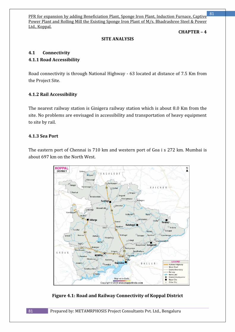
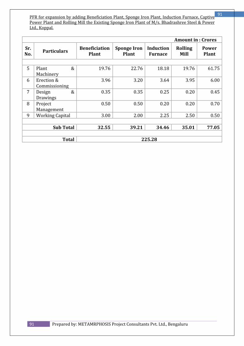
The plant location has been chosen close to the industries. The site located in theKunikere Village of Koppal Taluk & District. The average elevation 549 MSL and isgeographically located at 760 11’ 49.28” E Longitude & 150 19’ 27.77” N Latitude. Thenearest railway station is Ginigera Railway station, which is at a distance of 8 Km. theRoad connectivity is through NH - 63 located at distance of 8 Km from the plant. Hencethe transportation to various sites of finished products is easy and economical. Theestimated cost of the project is Rs. 225.28 Crores.
The manufacturing capacity of the Proposed Expansion Project is given in Table – 2.1.
Table 2.1: Proposed Manufacturing Facilities
Sr.No. Particulars Existing
Facility Proposed Facility
1 Sponge Iron Plant 2 X 100 TPD 2 X 100 TPD2 Induction Furnace -- 1 X 15TPD3 Captive Power Plant -- 15 MW (WHRB – 8 MW & AFBC –7 MW)4 Beneficiation Plant -- 0.6 MTPA5 Rolling Mill -- 1,20,000 TPA
PFR for expansion by adding Beneficiation Plant, Sponge Iron Plant, Induction Furnace, CaptivePower Plant and Rolling Mill the Existing Sponge Iron Plant of M/s. Bhadrashree Steel & PowerLtd., Koppal.
The project fall under category A, section 3 (a) of EIA Notification 14th September 2006and amendment thereof vide Notification no. S.O 3067 (E) dated 1st December 2009.2.3 Need for the Project and its Importance to the Country
2.3.1 Global Steel ScenarioSteel is one of the world’s most essential materials. It is fundamental to every aspect ofour lives, from infrastructure and transport to the tinplated steel can that preservesfood. It is one of the most important products of the modern world and is of strategicimportance to any industrial nation. From construction, industrial machinery andtransportation to consumer products, steel finds a wide variety of applications. It is alsoan industry with diverse technologies based on the nature and extent of use of rawmaterials. Steel’s great advantage is that it is 100% recyclable and can be reusedinfinitely. The industry uses advanced technologies and techniques to increaseproduction yield rates and to facilitate the use of by-products. As a result of the intrinsicrecyclability of steel, the value of the raw materials invested in steel production lasts farbeyond the end of a steel product’s life.Steel is critical simply because no other material has the same unique combination ofstrength, formability and versatility. Without being aware of it, society now depends onsteel. Humankind’s future success in meeting challenges such as climate change,poverty, population growth, water distribution and energy limited by a lower carbonworld depends on applications of steel. Steel plays a critical role in virtually every phasein our lives. The rails, roads and vehicles that make up our transport systems use steel.Steel provides a strong framework and connections in the buildings where we work,learn and live. It protects and delivers our water and food supply. It is a basiccomponent in technologies that generate and transmit energy. The World SteelAssociation (WSA) recently announced that the total crude steel production in 2016was 1628 million Tons which is 8 million Tons higher than the previous year (2015)production. Steel demand in emerging and developing economies (excl. China) isexpected to increase by 4.9% and 4.5% in 2018 and 2019 respectively.The Indian economy is stabilising from the impact of currency reform and GSTimplementation and steel demand is expected to accelerate gradually, mainly driven bypublic investment. Stronger growth is held back by still weak private investment. Globalsteel sector has seen significant growth after the turn of present century. The steel
PFR for expansion by adding Beneficiation Plant, Sponge Iron Plant, Induction Furnace, CaptivePower Plant and Rolling Mill the Existing Sponge Iron Plant of M/s. Bhadrashree Steel & PowerLtd., Koppal.
demand and the capacity have grown almost threefold over the last two decades. Thisrate of growth is unprecedented in the human history. Though it has started falteringwith steel demand in China moderating, there are some bright spots in the World whichraises possibility of revival of growth in the medium to long run. One of the keydeterminants of future growth will be the economic growth of India and relatedinfrastructure spends. The demand for steel has grown over time with increasingindustrialization, from 200 MT in 1976 to more than 1000 MT in 2015. However, it wasonly after the turn of the century that the global steel demand has increased rapidly.
In 2016, the world crude steel production reached 1630 million tonnes (mt) andshowed a growth of 0.6% over 2015. China remained world’s largest crude steel producer in 2016 (808 mt) followedby Japan (105 mt), India (96 mt) and the USA (79 mt). World Steel Association has projected Indian steel demand to grow by 6.1% in2017 and by 7.1% in 2018 while globally, steel demand has been projected togrow by 1.3% in 2017 and by 0.9% in 2018. Chinese steel use is projected toshow nil growth in 2017 and decline by 2% in 2018. Per capita finished steel consumption in 2016 is placed at 208 kg for world and493 kg for China by World Steel Association.
PFR for expansion by adding Beneficiation Plant, Sponge Iron Plant, Induction Furnace, CaptivePower Plant and Rolling Mill the Existing Sponge Iron Plant of M/s. Bhadrashree Steel & PowerLtd., Koppal.
1. India has seen nearly a century of Steel making as it stands on the threshold of a newera. The face of the Indian Iron and Steel Industry is changing at such a fast pacethat it is difficult to focus it now in the historical perspective. Steel is a core industryand thus its demand is strongly linked to overall level of economic activity in thecountry. Given the inherent long-term potential of the Indian economy and itscyclical nature, the long-term prospects of the Steel industry are fairly comfortable.Liberalization and the opening up of the economy have given a new vitality to thissector. Demand and production have been growing at a healthy rate for the past twoyears and forecast for the next ten years is very bright. The Indian Iron and Steelindustry today displays variety in size, ownership, technology and output. Theindustry was traditionally divided into main producers and so called secondarysector. This division is getting blurred by latest developments fuelled byliberalization and opening up of the economy, such as: Larger IF based units going on stream producing sophisticated finished productsas compared to small IF/IF units producing pencil ingots. Mini BF based plants being planned in the private sector. Growth in induction furnace units with sizeable production. High growth in Iron making sector with large gas based DRI units, coal basedSponge units and mini blast furnaces producing merchant grade pig Iron.
2. The Electric Steel industry, which initially started as a result of general Steelshortage and dual pricing policy in the country in the past, has been growingsignificantly in the recent years. The older units are modernizing while new unitsare being set up with latest technology enabling reduction in cost of production.3. The major factors contributing to the existence and growth of the industry are asfollows:
Lower investment cost and shorter gestation period as compared to BF-BOFroute of Steel making. Ability for wider dispersal. Less strain on transport and other infrastructural facilities. Fewer units operation. Non-dependence on metallurgical coke and coking coal. Less manpower per ton of Steel produced.
PFR for expansion by adding Beneficiation Plant, Sponge Iron Plant, Induction Furnace, CaptivePower Plant and Rolling Mill the Existing Sponge Iron Plant of M/s. Bhadrashree Steel & PowerLtd., Koppal.
Short conversion time for raw material to finished product. Lesser environmental and pollution problem. Flexibility in production of different qualities of Steel & Alloy Steel.
4. Besides the above factors, the Induction Furnace / Electric Arc furnace method ofmanufacturing Iron and Steel allows flexibility in the charge mix, leading to reducedelectricity consumption and decreased refractory consumption, which has resultedin the manufacture of international quality Steel. Since India has rich reserves ofcoal, the technology for manufacturing Sponge Iron is no more new. Sponge Ironproduction seems to have a bright future.
5. India is blessed with most of the principal raw materials in abundance, required forSteel industry and enjoys a unique position in the world in this respect. Under theprogramme of economic reforms introduced by the Government the approach toforeign investment has radically changed. Production and demand have startedpicking up as the recessionary conditions and trends prevalent earlier have nowended. However, in the new competitive environment, Steel producers have theirpriorities with special focus on quality, productivity, cost efficiency and alsoprofitability on the one hand and customer-oriented market strategies and productmix on the other. In the wake of globalization most of the developing countries likeIndia are presently undergoing structural adaptation with eagerly trying to cope upwith the tides and ebbs of the current economic influences of the developedcountries. And also they have modelled their way of developing throughindustrialization and mobilization of the potential surplus available.6. It is worth to note that,
After liberalization, there have been no shortages of Iron and Steel materials inthe country. Apparent consumption of finished carbon Steel increased from 65.87 MillionTons in 2010 to 79.80 Million Tons in 2015. The Steel industry in general is in the upswing due to strong growth in demandparticularly by the demand for Steel in Infrastructure industry.
Domestic Scenario
The Indian steel industry has entered into a new development stage, post de-regulation, riding high on the resurgent economy and rising demand for steel.
PFR for expansion by adding Beneficiation Plant, Sponge Iron Plant, Induction Furnace, CaptivePower Plant and Rolling Mill the Existing Sponge Iron Plant of M/s. Bhadrashree Steel & PowerLtd., Koppal.
Rapid rise in production has resulted in India becoming the 3rd largest producerof crude steel in 2015 as well as in 2016. The country was the largest producer ofsponge iron or DRI in the world during the period 2003-2015 and emerged asthe 2nd largest global producer of DRI in 2016 (after Iran). India is also the 3rdlargest finished steel consumer in the world and maintained this status in 2016.Such rankings are based on provisional data released by the World SteelAssociation for the above year. In a de-regulated, liberalized economic/market scenario like India theGovernment’s role is that of a facilitator which lays down the policy guidelinesand establishes the institutional mechanism/structure for creating conduciveenvironment for improving efficiency and performance of the steel sector. In this role, the Government has released the National Steel Policy 2017, whichhas laid down the broad roadmap for encouraging long term growth for theIndian steel industry, both on demand and supply sides, by 2030-31. The said Policy is an updated version of National Steel Policy 2005 which wasreleased earlier and provided a long-term growth perspective for the domesticiron and steel industry by 2019-20. The Government has also announced a policy for providing preference todomestically manufactured Iron & Steel products in Government procurement.This policy seeks to accomplish PM’s vision of ‘Make in India’ with objective ofnation building and encourage domestic manufacturing and is applicable on allgovernment tenders where price bid is yet to be opened. Further, the Policyprovides a minimum value addition of 15% in notified steel products which arecovered under preferential procurement. In order to provide flexibility, Ministryof Steel may review specified steel products and the minimum value additioncriterion.
7. Production
Steel industry was de-licensed and de-controlled in 1991 & 1992 respectively.India is currently the 3rd largest producer of crude steel in the world. In 2016-17 (prov.), production for sale of total finished steel (alloy + non alloy)was 100.74 mt, a growth of 10.7% over 2015-16. Production for sale of Pig Iron in 2016-17 (prov.) was 9.39 mt, a growth of 1.8%over 2015-16. India was the largest producer of sponge iron in the world during the period2003-2015 and was the 2nd largest producer in 2016 (after Iran). The coal basedroute accounted for 79% of total sponge iron production in the country in 2016-17 (prov).
PFR for expansion by adding Beneficiation Plant, Sponge Iron Plant, Induction Furnace, CaptivePower Plant and Rolling Mill the Existing Sponge Iron Plant of M/s. Bhadrashree Steel & PowerLtd., Koppal.
Data on production / production for sale of pig iron, sponge iron and totalfinished steel (alloy/stainless + non-alloy) are given below for last five years andApril-May 2017 India’s finished steel consumption grew at a CAGR of 5.69 per cent during FY08-FY18 to reach 90.68 MT. India’s crude steel and finished steel production increased to 102.34 MT and104.98 MT in 2017-18, respectively. In 2017-18, the country’s finished steel exports increased 17 per cent year-on-year to 9.62 million tonnes (MT), as compared to 8.24 MT in 2016-17. Exportsand imports of finished steel stood at 1.35 MT and 1.89 MT, during Apr-Jun 2018.
8. Pricing & Distribution
PFR for expansion by adding Beneficiation Plant, Sponge Iron Plant, Induction Furnace, CaptivePower Plant and Rolling Mill the Existing Sponge Iron Plant of M/s. Bhadrashree Steel & PowerLtd., Koppal.
Distribution controls on Iron & Steel removed except 5 priority sectors, viz.Defense, Railways, Small Scale Industries Corporations, Exporters of EngineeringGoods and North Eastern Region. Allocation to priority sectors is made by Ministry of Steel. Government has no control over prices of Iron & Steel. Open market prices are generally on rise. Price increases of late have taken place mostly in long products than flatproducts.
9. Opportunities for growth of Iron and Steel in Private SectorThe New Industrial policy has opened up the Iron & Steel sector for private investmentby (a) removing it from the list of industries reserved for public sector and (b)exempting it from compulsory licensing. Imports of foreign technology as well asforeign direct investment are freely permitted up to certain limits under an automaticroute. Ministry of Steel plays the role of facilitator, providing broad directions andassistance to new and existing Steel plants, in the liberalized scenario.The New Industrial Policy Regime
The New Industrial policy opened up the Indian iron and steel industry for privateinvestment by (a) removing it from the list of industries reserved for public sector and(b) exempting it from compulsory licensing. Imports of foreign technology as well asforeign direct investment are now freely permitted up to certain limits under anautomatic route. Ministry of Steel plays the role of a facilitator, providing broaddirections and assistance to new and existing steel plants, in the liberalized scenario.The Growth Profile
(i) Steel: The liberalization of industrial policy and other initiatives taken by theGovernment have given a definite impetus for entry, participation and growth of theprivate sector in the steel industry. While the existing units are beingmodernized/expanded, a large number of new steel plants have also come up indifferent parts of the country based on modern, cost effective, state of-the-arttechnologies. In the last few years, the rapid and stable growth of the demand side hasalso prompted domestic entrepreneurs to set up fresh green-field projects in differentstates of the country.
PFR for expansion by adding Beneficiation Plant, Sponge Iron Plant, Induction Furnace, CaptivePower Plant and Rolling Mill the Existing Sponge Iron Plant of M/s. Bhadrashree Steel & PowerLtd., Koppal.
Crude steel capacity was 126.33 mt in 2016-17 (prov.), up by 3.6% over 2015-16 andIndia, which emerged as the 3rd largest producer of crude steel in the world in 2016 asper provisional ranking released by the World Steel Association, has to its credit, thecapability to produce a variety of grades and that too, of international quality standards.The country is expected to become the 2nd largest producer of crude steel in the worldsoon.(ii) Pig Iron: India is also an important producer of pig iron. Post-liberalization, withsetting up several units in the private sector, not only imports have drastically reducedbut also India has turned out to be a net exporter of pig iron. The private sectoraccounted for 92% of total production for sale of pig iron in the country in 2016-17(prov.). The production for sale of pig iron has increased from 1.6 mt in 1991-92 to 9.39mt in 2016-17 (prov.).(iii) Sponge Iron: India, world’s 2nd largest producer of sponge iron (2016, prov.), has ahost of coal based units located in the mineral-rich states of the country. Over the years,the coal based route has emerged as a key contributor and accounted for 79% of totalsponge iron production in the country. Capacity in sponge iron making too hasincreased over the years and stood at around 43 mt (2015-16).10.InvestmentsSteel industry and its associated mining and metallurgy sectors have seen a number ofmajor investments and developments in the recent past. According to the data releasedby Department of Industrial Policy and Promotion (DIPP), the Indian metallurgicalindustries attracted Foreign Direct Investments (FDI) to the tune of US$ 10.84 billion inthe period April 2000–June 2018.Some of the major investments in the Indian steel industry are as follows:
JSW Steel will be looking to further enhance the capacity of its Vijayanagar plantfrom 13 MTPA to 18 MTPA. In June 2018, the company had announced plans toexpand the plant’s production capacity to 13 MTPA by 2020 with an investmentof Rs 7,500 crore (US$ 1.12 billion). Vedanta Star Ltd has outbid other companies to acquire Electrosteel Steels forUS$ 825.45 million. Tata Steel won the bid to acquire Bhushan Steel by offering a consideration ofUS$ 5,461.60 million.
PFR for expansion by adding Beneficiation Plant, Sponge Iron Plant, Induction Furnace, CaptivePower Plant and Rolling Mill the Existing Sponge Iron Plant of M/s. Bhadrashree Steel & PowerLtd., Koppal.
JSW Steel has planned a US$ 4.14 billion capital expenditure programme toincrease its overall steel output capacity from 18 million tonnes to 23 milliontonnes by 2020. Tata Steel has decided to increase the capacity of its Kalinganagar integratedsteel plant from 3 million tonnes to 8 million tonnes at an investment of US$ 3.64billion.
2.4 Demand – Supply Gap
Industry dynamics including demand – availability of iron and steel in the country arelargely determined by market forces and gaps in demand-availability are met mostlythrough imports. Interface with consumers exists by way of meeting of the Steel Consumers’Council, which is conducted on regular basis. Interface helps in redressing availability problems, complaints related to quality.
2.5 Domestic / Export Markets2.5.1 Import
Iron & steel are freely importable as per the extant policy. Data on import of total finished steel (alloy/stainless + non alloy) is givenbelow for last five years and April-May 2017:
2.5.2 Export
Iron & steel are freely exportable. India emerged as a net exporter of total finished steel in 2016-17 (prov.) Data on export of total finished steel (alloy/stainless + non alloy) is given belowfor last five years and April-May 2017
PFR for expansion by adding Beneficiation Plant, Sponge Iron Plant, Induction Furnace, CaptivePower Plant and Rolling Mill the Existing Sponge Iron Plant of M/s. Bhadrashree Steel & PowerLtd., Koppal.
Karnataka is one amongst the industrially developed States in the Country. The Statehas potential to stand out on the fore front and has been focusing on development ofindustries, trade and service sectors.The State Government understands that the challenges posed due to global economicrecession have to be addressed to promote economic growth of the State. A stimulusto boost economic activities needs to be given to sustain the current pace of over alldevelopment. Further, the state is endowed with rich natural resources across theState and such resources need to be optimally utilized for the benefit of local people.Value addition to resources is one of the efficient ways of optimizing the locallyavailable wealth. This will also help to ensure uniform spread of industries andeconomic activities throughout the state and will accelerate the pace of developmentespecially in the district of North Karnataka. Through these measures, theGovernment would be able to readdress the serious issue of regional imbalances indevelopment.The state government realizes the limitation of agriculture sector to generate largescale employment to the local youths. About 56% of the state’s workforce is estimatedto contribute 19.13% of the GSDP. It is agreed that, the implementing sector has highpotential to create maximum employment that too, to all sections and level of theaspirants. In order to provide suitable environment for investors, the stategovernment has already enacted Karnataka Industries (Facilities) Act, 2002. Due tothe progressive measure and pro-active mind set of the government, today, theKarnataka has been recognized as one of the preferred investment destination bothfor domestic and overseas investors.
PFR for expansion by adding Beneficiation Plant, Sponge Iron Plant, Induction Furnace, CaptivePower Plant and Rolling Mill the Existing Sponge Iron Plant of M/s. Bhadrashree Steel & PowerLtd., Koppal.
The state government has introduced Industrial Policy 2006-11 with an aim toincrease the growth of GDP, strengthen manufacturing industries, increase share ofexports from Karnataka, to generate additional employment of at least 10 lakhpersons in the manufacturing and service sectors, reduce regional imbalance andultimately aim at overall socio-economic development of the state.In the meantime, the Government of India enacted Micro, Small and MediumEnterprises Development Act, 2006 and requested all the States to provide requiredsupport and encouragement to make MSMEs more competitive. In order to make thestate more attractive and investors friendly, there was a need to focus more oninclusive industrial development, comprehensive HRD programme’s special attentiontowards development of sector specific zones, classification of Taluks according to Mr.D M Nanjundappa Committee Report, attractive package of incentives andconcessions, encouragement for existing industries to take up expansion,modernization and diversification etc.The state also understands the need to provide stimulus measures for industries tocombat the prevailing financial crisis. Keeping these points in view, the state intendsto formulate a new Industrial Policy with a determination to provide requiredplatform for all the investors.This policy is framed with the broad guiding principles of creation of employmentdevelopment of backward regions and value addition to local resources.2.6.2 Vision
To build prosperous Karnataka through development of human & natural resourcesin a systematic, scientific and sustainable manner.2.6.3 Mission
To create enabling environment for the robust industrial growth. To ensure inclusive industrial development in state. To provide additional employment for about 10 lakh person by 2014. To enhance the contribution of manufacturing sector to the state’s GDP from the current level of 17% to 20% by the end of policy period.
PFR for expansion by adding Beneficiation Plant, Sponge Iron Plant, Induction Furnace, CaptivePower Plant and Rolling Mill the Existing Sponge Iron Plant of M/s. Bhadrashree Steel & PowerLtd., Koppal.
Thrust on provision of world-class infrastructural facilities for industries withactive participation of private sector/industry. Development of sector-wise industrial zones for optional utilization of localnatural and human resources so as to minimize migration of people to urbancenters. Simplification of land acquisition procedures with emphasis on inclusivedevelopment. Safeguarding the socio-economic interests of both farmers and investors whileacquisition of land. Referential treatment for MSME sector enabling to meet the global Challenges. Attractive employment and performance linked package of incentives andconcessions to attract investments to backward regions and also to provideleverage to MSME sector. Thrust on development of MSME sector through attractive package ofincentives & concessions. Tailor made package of incentives to larger projects having wider positiveimplication on the state’s economy to leverage a better edges over othercompeting states. Additional incentives for entrepreneurs belonging to under privileged sectionsof the society to bring them to the main stream in order to achieve muchneeded inclusive growth. Focus on skill development in order to enhance the employment ability ofyouth especially women and also to make ready-to-employ human resource tothe industry. Inculcate entrepreneurial qualities amongst local youth in general and womenin particular and motivate them to take up self employment by extendinghandholding support. Create level playing environment for all investors/private sector players byenhancing the facilitation mechanism enabling to do their business with easeand less transaction cost. Appropriate provision for the protection of environment and to encourageenergy & water conservation measures in industry / project through go-greenstrategy.
PFR for expansion by adding Beneficiation Plant, Sponge Iron Plant, Induction Furnace, CaptivePower Plant and Rolling Mill the Existing Sponge Iron Plant of M/s. Bhadrashree Steel & PowerLtd., Koppal.
Some of the other recent government initiatives in this sector are as follows:
An export duty of 30 per cent has been levied on iron ore^ (lumps and fines) toensure supply to domestic steel industry. Government of India’s focus on infrastructure and restarting road projects isaiding the boost in demand for steel. Also, further likely acceleration in ruraleconomy and infrastructure is expected to lead to growth in demand for steel. The Union Cabinet, Government of India has approved the National Steel Policy(NSP) 2017, as it seeks to create a globally competitive steel industry in India.NSP 2017 targets 300 million tonnes (MT) steel-making capacity and 160 kgs percapita steel consumption by 2030. The Ministry of Steel is facilitating setting up of an industry driven SteelResearch and Technology Mission of India (SRTMI) in association with the publicand private sector steel companies to spearhead research and developmentactivities in the iron and steel industry at an initial corpus of Rs 200 crore (US$30 million).
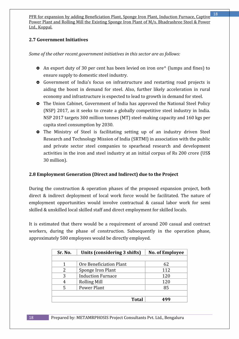
2.8 Employment Generation (Direct and Indirect) due to the Project
During the construction & operation phases of the proposed expansion project, bothdirect & indirect deployment of local work force would be facilitated. The nature ofemployment opportunities would involve contractual & casual labor work for semiskilled & unskilled local skilled staff and direct employment for skilled locals.It is estimated that there would be a requirement of around 200 casual and contractworkers, during the phase of construction. Subsequently in the operation phase,approximately 500 employees would be directly employed.
Sr. No. Units (considering 3 shifts) No. of Employee1 Ore Beneficiation Plant 622 Sponge Iron Plant 1123 Induction Furnace 1204 Rolling Mill 1205 Power Plant 85Total 499
PFR for expansion by adding Beneficiation Plant, Sponge Iron Plant, Induction Furnace, CaptivePower Plant and Rolling Mill the Existing Sponge Iron Plant of M/s. Bhadrashree Steel & PowerLtd., Koppal.
3.1 Type of Project including interlinked and interdependent projects, if any.The proposed project is a brown field expansion project involving the expansion byadding ore beneficiation plant, sponge iron plant, induction furnace, rolling mill andcaptive power plant in the existing sponge iron plant within the existing land 30 Acresarea available with BSPL. Land documents are enclosed as Annexure No – 4.
3.2 Location of the Project
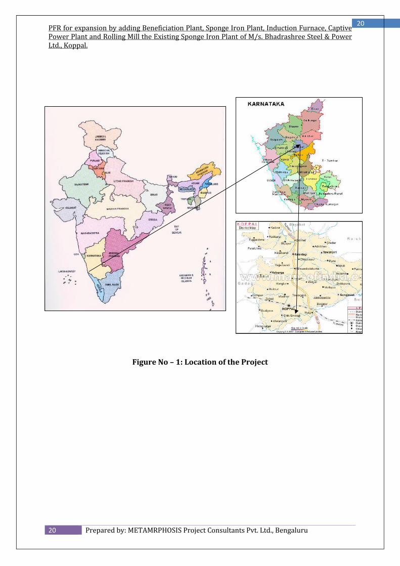
The plant location has been chosen close to the industries. The site located in theKunikere Village of Koppal Taluk & District. The average elevation 549 MSL and isgeographically located at 760 11’ 49.28” E Longitude & 150 19’ 27.77” N Latitude. Thenearest railway station is Ginigera Railway station, which is at a distance of 8 Km. theRoad connectivity is through NH - 63 located at distance of 8 Km from the plant. Hencethe transportation to various sites of finished products is easy and economical. Locationof the Project is given in Figure No – 1 and Google Map is given in Figure No – 2. Sitephotographs are given in Photo No – 1.
PFR for expansion by adding Beneficiation Plant, Sponge Iron Plant, Induction Furnace, CaptivePower Plant and Rolling Mill the Existing Sponge Iron Plant of M/s. Bhadrashree Steel & PowerLtd., Koppal.
PFR for expansion by adding Beneficiation Plant, Sponge Iron Plant, Induction Furnace, CaptivePower Plant and Rolling Mill the Existing Sponge Iron Plant of M/s. Bhadrashree Steel & PowerLtd., Koppal.
PFR for expansion by adding Beneficiation Plant, Sponge Iron Plant, Induction Furnace, CaptivePower Plant and Rolling Mill the Existing Sponge Iron Plant of M/s. Bhadrashree Steel & PowerLtd., Koppal.
PFR for expansion by adding Beneficiation Plant, Sponge Iron Plant, Induction Furnace, CaptivePower Plant and Rolling Mill the Existing Sponge Iron Plant of M/s. Bhadrashree Steel & PowerLtd., Koppal.
3.3 Details of Alternate Sites Considered and the Basis of Selecting the ProposedSite
The expansion of Sponge Iron Plant is being planned by adding Beneficiation Plant,Sponge Iron Plant, Induction Furnace, Captive Power Plant and Rolling Mill. This is abrown field expansion, within the available land area of 30 acres and utilizing existinginfrastructure. Hence, Alternative site was not examined.3.4 Size or Magnitude of Operation
The proposed expansion project after its completion will facilitate in production alongwith value added long and flat steel products to meet the increasing demand of thecustomers and country`s infrastructure development. The proposed facilities will be setup within the area of about 30 acres.3.5 Project Description with Process Details (a schematic diagram/flow chartshowing the project layout, component of the project)
Plant Layout with all the component if the project is enclosed as Drawing No – 1.
3.5.1 Beneficiation Plant
Beneficiation process is always designed for a particular quality of feed and that tooafter conducting extensive laboratory tests. Since low grade ore/fines are to beprocured from mines/market, there is little control on sustained quality, which is animportant factor in designing an efficient & cost effective beneficiation plant.The high levels of silica and clay within this feed reduces the overall Fe value of thematerial which is a barrier to the cost effective use of this material in steel productionfor the reasons stated earlier. Therefore, any method which can remove contaminantssuch as silica, clay and alumina is attractive. Those who operate within the market havea long history of washing iron ore reserves as a means of improving the Fe grade of thematerial, thus creating greater efficiencies in production.The washing process involves the removal of surface contaminants from the iron oreparticles. The extensive research we have conducted into the nature of the feed materialhas shown that the highest levels of contaminants exist in the finest particle sizes. Whatwe also know is that the contaminants are of a much lower density than the target
PFR for expansion by adding Beneficiation Plant, Sponge Iron Plant, Induction Furnace, CaptivePower Plant and Rolling Mill the Existing Sponge Iron Plant of M/s. Bhadrashree Steel & PowerLtd., Koppal.
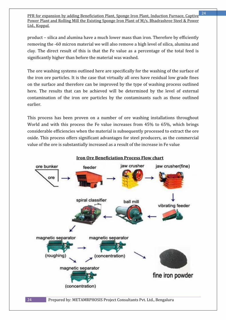
product – silica and alumina have a much lower mass than iron. Therefore by efficientlyremoving the -60 micron material we will also remove a high level of silica, alumina andclay. The direct result of this is that the Fe value as a percentage of the total feed issignificantly higher than before the material was washed.The ore washing systems outlined here are specifically for the washing of the surface ofthe iron ore particles. It is the case that virtually all ores have residual low grade fineson the surface and therefore can be improved by the type of washing process outlinedhere. The results that can be achieved will be determined by the level of externalcontamination of the iron ore particles by the contaminants such as those outlinedearlier.This process has been proven on a number of ore washing installations throughoutWorld and with this process the Fe value increases from 45% to 65%, which bringsconsiderable efficiencies when the material is subsequently processed to extract the oreoxide. This process offers significant advantages for steel producers, as the commercialvalue of the ore is substantially increased as a result of the increase in Fe value
Iron Ore Beneficiation Process Flow chart
PFR for expansion by adding Beneficiation Plant, Sponge Iron Plant, Induction Furnace, CaptivePower Plant and Rolling Mill the Existing Sponge Iron Plant of M/s. Bhadrashree Steel & PowerLtd., Koppal.
3.5.1.1 Physical and Chemical Characterization Studies
The size analysis of the received Iron ore sample, were carried out by wet sievingtechniques to know the average particle size of the sample. The different size fractionsthus obtained were subjected to chemical analysis to ascertain the different quantitativeelemental composition of the sample. The complete chemical analysis of the ore anddifferent size fractions were carried out by X-ray florescence technique and wetchemical analysis. The XRF analyses were carried out against the standard calibratedsamples of similar values. The loss on ignition (LOI) of Iron ore samples was determinedby igniting around 2.0 gm of sample at about 1000 C for four hours in a muffle furnacein silica crucible.Closed sized classified samples were examined under stereomicroscope by preparingthe corresponding grain slides for identification of different minerals. The X-raydiffraction studies of selected samples were also carried out using a Philips modeldiffract meter with CuK radiation. The bulk sample was crushed to below 1 mm size andwet sieved into different size fractions. The size fractions were mounted in resin withhardner and polished following standard procedures. The polished sections werestudied under reflected light microscope and the particles of different typologies werecounted.3.5.1.2 Grinding Studies
In order to increase the grade of Iron ore and for the subsequent liberation of Ironvalues from the locked particles, the samples were subjected to wet grinding togenerate different size particles. A standard ball mill with required weight of balls asper Bonds formula at 45% filling was used. The grinding was carried out in batch priorto different beneficiation studies. The objective is to achieve the maximum liberation ofthe Iron particles from the associated gangues due to reduction in size. The large-scalecontinuous grinding studies were also produce samples for further investigations and toestablish grinding parameters. All the grinding studies were carried out at 40% solidsconsistency in the ball mill.3.5.1.3 Beneficiation Studies
Beneficiation studies using various techniques such as hydrocyclone, spiral, magneticseparation, flotation etc. were carried out to develop a suitable process flowsheet as astep towards the upgradation of Iron values and to reduce the gangue content. The
PFR for expansion by adding Beneficiation Plant, Sponge Iron Plant, Induction Furnace, CaptivePower Plant and Rolling Mill the Existing Sponge Iron Plant of M/s. Bhadrashree Steel & PowerLtd., Koppal.
required separation technique was selected based on particle size and the propertiesfor effective separation. Initially, the Iron Ore ore fines were ground to required sizeand then subjected to separation. The sample was ground to below 1.0 mm size for IronOre fines and less than 100 microns for BHQ ore.3.5.1.4 Spiral
The spiral concentrator was used to enrich the Iron content of the classified sample(hydro-cyclone underflow). The spiral is an energy saving gravity equipment wherelarge quantities of sample can be fed for pre-concentrations. In the spiral study, the Ironore sample was fed to the centrifugal pump at the required solids consistency and theslurry was kept re-circulating for a predetermined time. The entire concentrate andtailings were collected after attaining the steady state. The concentrates in some caseswere cleaned to improve the grade of products. All the products thus obtained weredried, weighed, and analyzed.3.5.1.5 Wet High Intensity Magnetic Separation
The wet high intensity magnetic separator (WHIMS) and high gradient magneticseparator (HGMS) were used at different magnetic field intensities to recover the fineIron values from the hydrocyclone over flow or spiral tailings. Both the separators haveprovision for different magnetic groves of width and matrix with variable currents toprovide different magnetic intensities. A desired concentration of solids was passedthrough the magnetic separator. In some cases the magnetic products were cleaned insecond stage to enhance the quality of the product from first stage separation.3.5.1.6 Floatation
Batch flotation studies were carried out to select either direct or reverse flotationtechnique to optimize reagent combination and to establish the number of stages ofoperations. Denver D-12 sub-aeration flotation machine was used for the batch flotationstudies. Both cationic (dodecyl amine) and anionic (oleic acid) reagents were used ascollectors while MIBC was used as the other collector. The column flotation studieswere carried out by using glass column designed and fabricated at our laboratory. Thecolumn was operated at nominal capacity of 20 kg of Iron ore fines per hour with thehelp of a peristaltic pump. Both the concentrate and tailings were collected separatelyafter attaining the steady state and analyzed for Iron content.
PFR for expansion by adding Beneficiation Plant, Sponge Iron Plant, Induction Furnace, CaptivePower Plant and Rolling Mill the Existing Sponge Iron Plant of M/s. Bhadrashree Steel & PowerLtd., Koppal.
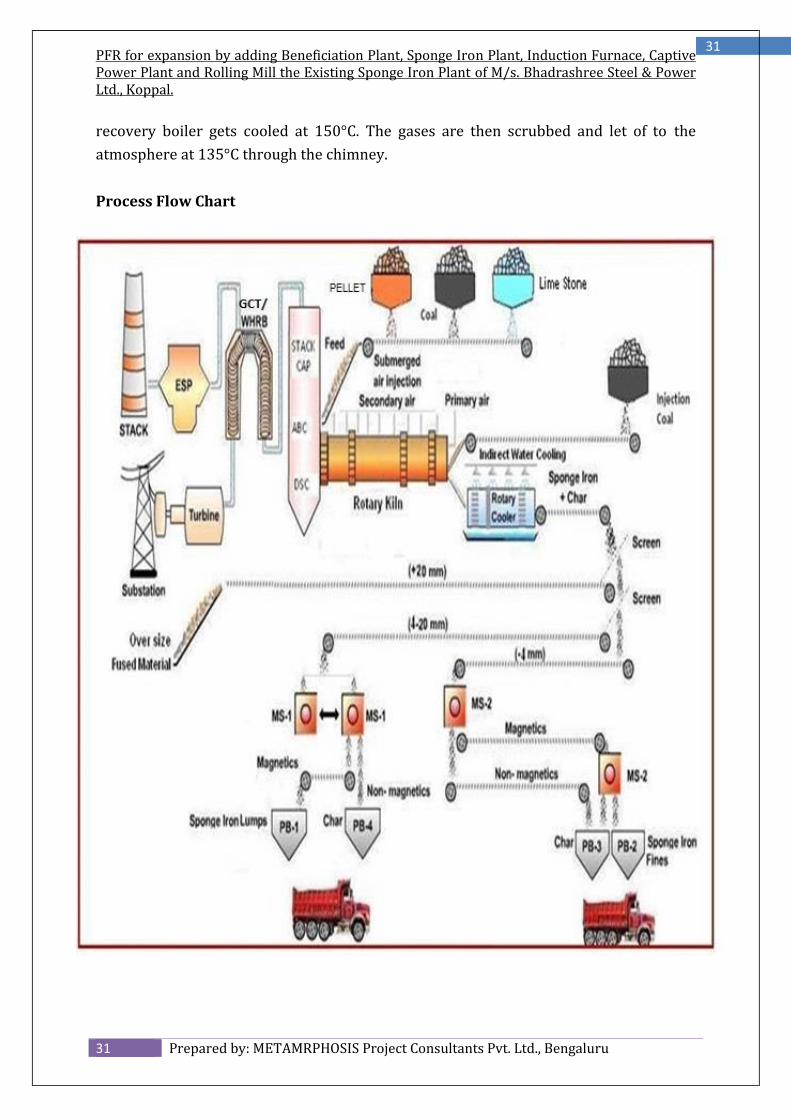
Generally in sponge iron process, reduction is conducted in a refractory lined rotarykiln. The kiln of suitable size generally inclined at 2.5 % slope rest on four supportstations. The transport rate of materials through the kiln can be controlled by varyingits slope and speed of rotation. There are inlet and outlet cones at opposite ends of thekiln that are cooled by individual fans. The kiln shell is provided with small samplingports, as well as large ports for rapid removal of the contents in case of emergency orfor lining repairs. The longitudinal positioning of the kiln on its riding rings is controlledhydraulically.The coal and Pellet (iron) are metered into the high end of the inclined kiln. A portion ofthe coal is also injected pneumatically from the discharge end of the kiln. The burdenfirst passes through a pre-heating zone where coal de-volatilization takes place andPellet (iron) is heated to pre-heating temperature for reduction.The product (DRI) is discharged from the kiln at about 1000°C. An enclosed chute at thekiln discharge end equipped with a lump separator and an access door for removinglumps transfers the hot DRI to a rotary cooler. The cooler is a horizontal revolvingcylinder of appropriate size. The DRI is cooled indirectly by water spray on the coolerouter surface. The cooling water is collected in troughs below the cooler and pumped tothe cooling tower for recycling along with make-up water. Solids discharged to thecooler through an enclosed chute are cooled to about 100°C without air contact. Agrizzly in the chute removes accretions that are large to plug up or damage the coolerdischarge mechanisms. The product is screened to remove the plus 20 mm DRI. Theundersize a mix of DRI, Dolochar and coal ash is screened into +/- 4 mm fractions. Eachfraction passes through a magnetic separator. The non-magnetic portion of the plus 4mm fraction is mostly char and can be recycled to the kiln if desired. The nonmagneticportion of - 4 mm fraction mostly spent lime, ash and fine char is discarded. Themagnetic portion of each fraction is DRI. The plus 4 mm fraction can be used directlyfor steel making and the finer fraction can be briquetted / collected in bags.The kiln waste gases at about 950°-1100°C pass through a dust settling chamber whereheavier dust particles settle down due to sudden decrease in velocity of gases. The fluegases then pass through an after burning chamber where un-burnt combustibles areburnt by blowing excess air. The temperature of the after burner chamber, at times, iscontrolled by water sprays. The burnt gases then pass through a down duct intoevaporation cooler where the temperature is brought down and through pollution
PFR for expansion by adding Beneficiation Plant, Sponge Iron Plant, Induction Furnace, CaptivePower Plant and Rolling Mill the Existing Sponge Iron Plant of M/s. Bhadrashree Steel & PowerLtd., Koppal.
control equipment namely GCT/ WHRB, ESP, Bag filter and Wet Scrapper where balancedust particles are separated. Then the gas is let off into the atmosphere through stackvia ID fan.Coal based large plant is equipped with waste heat recovery system, the flue gases afterthe After Burning Chamber pass through an elbow duct to waste heat boiler wheresensible heat of the gases is extracted. The gas is then let off into the atmosphere afterpassing through pollution control equipment like ESP, ID fan and stack. In solid basedprocesses, the non-coking coal and Pellet (iron) which are at intimate contact startreacting at the prevailing temperature.For high Kiln efficiency the reheated zone is made as short as possible usually 40 to50% of kiln length. Reduction begins when the charge reaches temperature in excess of900°C when the carbon gasification reaction starts generating carbon monoxide. Tomaintain a uniform reduction zone temperature by burning combustibles released toform the bed, air is blown by shell mounted fans, feed air into the freeboard gas stream,through burner tube space uniformly along the length of the kiln. Air is introducedaxially in to the kiln and additional combustion air is blown into the kiln through acentral burning airport of the discharge end.The solids are discharged forms the rotary kiln via transfer chute into a sealed rotarycooler. Water sprays (indirect cooling) on the cooler shell reduces the temperature ofsolids to about 95 °C in a non-oxidizing atmosphere.External lifter aide heat transfer in the cooler discharge material that are continuouslyseparated into DRI, DRI fines, non-magnetic by a system of screen and magneticseparation. Char is separated from the waste by gravity separation and utilized as RawMaterial for AFBC Boiler.The SL/RN process kilns are now equipped with nozzles for under-bed injection ofabout 25% of the process air in the preheating zone of kiln. The air is available forcombustion of the volatile matter in the coal within the bed in the preheating zone. As aresult, the length of preheating zone of the kiln is reduced because of improved heattransfer and fuel utilization. More of the kiln length can therefore be used as a reductionzone.
PFR for expansion by adding Beneficiation Plant, Sponge Iron Plant, Induction Furnace, CaptivePower Plant and Rolling Mill the Existing Sponge Iron Plant of M/s. Bhadrashree Steel & PowerLtd., Koppal.
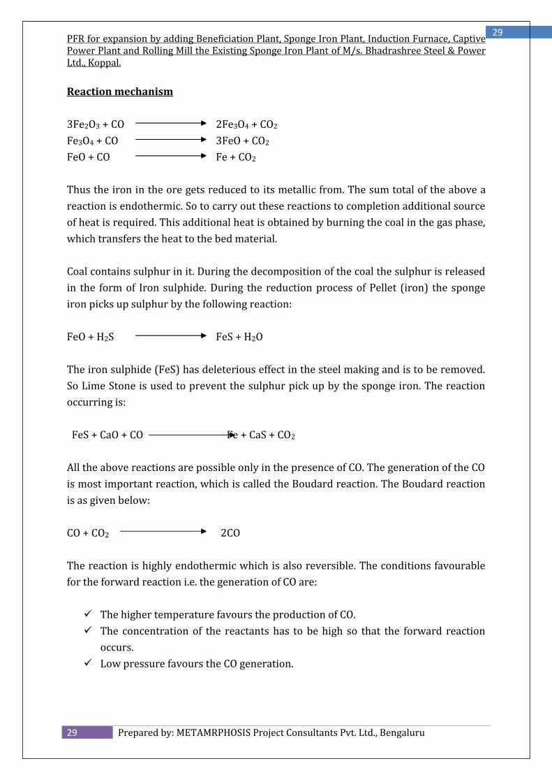
3Fe2O3 + CO 2Fe3O4 + CO2Fe3O4 + CO 3FeO + CO2FeO + CO Fe + CO2Thus the iron in the ore gets reduced to its metallic from. The sum total of the above areaction is endothermic. So to carry out these reactions to completion additional sourceof heat is required. This additional heat is obtained by burning the coal in the gas phase,which transfers the heat to the bed material.Coal contains sulphur in it. During the decomposition of the coal the sulphur is releasedin the form of Iron sulphide. During the reduction process of Pellet (iron) the spongeiron picks up sulphur by the following reaction:FeO + H2S FeS + H2OThe iron sulphide (FeS) has deleterious effect in the steel making and is to be removed.So Lime Stone is used to prevent the sulphur pick up by the sponge iron. The reactionoccurring is:FeS + CaO + CO Fe + CaS + CO2
All the above reactions are possible only in the presence of CO. The generation of the COis most important reaction, which is called the Boudard reaction. The Boudard reactionis as given below:CO + CO2 2COThe reaction is highly endothermic which is also reversible. The conditions favourablefor the forward reaction i.e. the generation of CO are: The higher temperature favours the production of CO. The concentration of the reactants has to be high so that the forward reactionoccurs. Low pressure favours the CO generation.
PFR for expansion by adding Beneficiation Plant, Sponge Iron Plant, Induction Furnace, CaptivePower Plant and Rolling Mill the Existing Sponge Iron Plant of M/s. Bhadrashree Steel & PowerLtd., Koppal.
All the above reactions occur in the bed phase. In the gas phase the following reactionsoccur:CH4 + 2O2 CO2 + 2H2O2CO + O 2CO2C + O2 CO2All these reactions are exothermic. They supply the heat required for the reactions inthe bed phase to occur. The oxygen required for the burning of these combustibles issupplied from the air tubes placed along the length of the kiln. By controlledcombustion, the temperature in the various zones is maintained so that the reduction isproper and to sufficient degree.The product quality is defined by the degree of metallization. The degree ofmetallization iron is defined as the ratio of the metallic iron to the total iron present.
Fe (metallic)Degree of Metallization = -------------------- x 100Fe (total)The reduction of Pellet (iron) is topo-chemical i.e. the reduction proceeds from thesurface in the core. The Pellet (iron) on partial reduction has all the different stages ofthe reduction.The hot material, after the reduction is complete, is transferred to the total cooler viathe transfer chute. The cooler is 3.2 meters in diameter and 44 meters long and made upof Mild Steel sheet. It is also inclined at 2.5% approximately. The water is sprayed on thetop of the shell which cools the material inside the cooler indirectly. By this the materialgets cooled to 80°-90°C. and is discharged on the belt conveyor by the double pendulumvalve. The double pendulum valve acts as the seal for the prevention of the atmosphericair into the kiln cooler system.The gases, which flow in the counter current direction of the material, go to the dust-settling chamber where the heavier particles settle down. These particles arecontinuously removed by the wet scrapper system. The gases then pass to the afterburner chamber where the residual carbon or CO are burned by the excess air available.The gases are at high temperature and have lot of heat energy, which can be utilized forthe power generation through the waste heat recovery boiler. The hot gas after the heat
PFR for expansion by adding Beneficiation Plant, Sponge Iron Plant, Induction Furnace, CaptivePower Plant and Rolling Mill the Existing Sponge Iron Plant of M/s. Bhadrashree Steel & PowerLtd., Koppal.
recovery boiler gets cooled at 150°C. The gases are then scrubbed and let of to theatmosphere at 135°C through the chimney.Process Flow Chart
PFR for expansion by adding Beneficiation Plant, Sponge Iron Plant, Induction Furnace, CaptivePower Plant and Rolling Mill the Existing Sponge Iron Plant of M/s. Bhadrashree Steel & PowerLtd., Koppal.
The following major areas are envisaged for the proposed Sponge Iron Unit.a. Raw materials preparation, Storage, and handling,b. Kiln and Cooler axis,c. Product Separation,d. Utility Services,e. Waste gas Cleaning system,f. Power Supply and Distribution,g. Quality Control Facilities,
The raw material storage is located close to the raw material handling plant and the daybins. The kiln cooler building is also located close to the raw material handling plant. Awell planned and laid out road network is proposed inside the plant connecting all theunits of the plant. Provision has been kept in the layout for providing future expansionand downstream.3.5.2.1 Raw material preparation, storage and handling
Iron Ore, Coal and sized Lime Stone would be received from the mines/ suppliersdirectly by road, and unloaded and stacked in the raw material yard. Raw materialhandling is consisting two circuits namely, Iron Ore Circuit and Coal Circuit, whichcontaining crushing, screening, conveying and storage Coal circuit and separatelyconveying and storage of Iron Ore circuit.The material would be transported by means of Tippers/Dozers and unloaded into theGround Hoppers. Adequate weighing facilities would be provided for all the incomingmaterials to the storage yard and outgoing materials from the storage yard.3.5.2.2 Vibrating Feeders
All vibrating feeders shall be of electro-mechanical design driven by unbalanced motors.The vibrating force shall be generated by rotation of eccentric mass of motor. Thelength, width, slope etc., of the pan shall be so selected that material from the storagebin do not flow out when the gate is open but the feeder is not in operation.3.5.2.3 Belt Conveyors
The selection and design of belt conveyors shall generally be guided by Indianstandards unless otherwise stated in the specification.
PFR for expansion by adding Beneficiation Plant, Sponge Iron Plant, Induction Furnace, CaptivePower Plant and Rolling Mill the Existing Sponge Iron Plant of M/s. Bhadrashree Steel & PowerLtd., Koppal.
The belt conveyors shall be designed such that similar components of various beltconveyors are interchangeable to the extent feasible. Special emphasis shall be given forstandardization of belt, pulley, idler, bearing, drive unit components i.e. motor, coupling,gear box and brake/hold back. All components of the belt conveyor shall be designed forstarting with material (corresponding to design capacity) of belt.3.5.2.4 Vibrating Screen
All linear motion vibrating screen shall be of unbalanced motor driven type design andof adequate size to achieve desired separation of materials.The screen body shall be fabricated from steel plates and structural of adequatestrength. All welded parts shall be stress relieved and all holes shall be drilled. Sharpedge on the screen body shall be avoided and adequately reinforced at supportingpoints where vibrating mechanism is connected. It shall be provided with suitable backplate at feed end to prevent spillage of material. The screen shall be supported byadequate number of springs to give rigidity to the equipment preventing minimumtransmission of dynamic force to the supporting structure. The spring shall haveuniform spring constant throughout its operating range.The material of screen cloth shall be selected based on type and physical properties ofmaterials to be handled. The clamping arrangement for screen cloth shall be suitable toretain proper tension and also to allow easy replacement of screen clothes.3.5.2.5 Crusher & Screen House (Coal)
From ground hopper Coal is conveyed to Coal Crusher & Screen House for crushing &screening here there are two stage crusher viz. Primary & Secondary and two screensRaw Coal Screen & Crushed Coal Screen. The sized Coal is conveyed to Surge Hopperand oversize Coal is carried to Junction House through return conveyor, which is againfeed to Coal Crusher & Screen House.3.5.2.6 Stock House
From Surge Hopper raw material is being brought to the Day Bin or Stock Househousing for storing various raw materials like Coal, Pellet (iron) & Limestone thebunkers shall be designed to store 1 day requirement to feed into kilns. It isrecommended to fill all the bunkers by 90% of its capacity.
PFR for expansion by adding Beneficiation Plant, Sponge Iron Plant, Induction Furnace, CaptivePower Plant and Rolling Mill the Existing Sponge Iron Plant of M/s. Bhadrashree Steel & PowerLtd., Koppal.
Weigh Feeders are provided below the raw material bins for weighing. So, thatpredetermined quantities of Pellet (iron), Coal and Limestone from the bins shall beconveyed to the Kiln Feed Building by means of feed conveyor.3.5.2.8 Kiln & Cooler Axis
The raw material from Stock House is being feed into the Kiln from inlet through FeedTube. A portion of fine coal will be injected from the discharge end of the kiln usingrotary air lock feed and coal throw pipe. The coal is injected with the air supplied byTwin lobe Compressor specially designed for this purpose.3.5.2.9 Kiln
The kiln can be divided in three zones i.e. Kiln Inlet Zone (Pre Heating Zone), ReactionZone & Kiln Outlet Zone. Inside the kiln, the raw materials would be dried and heated tothe reduction temperature of approx. 1000° C. Reducing carbon monoxide inside thekiln would reduce the iron oxides of the ore to metallic iron. The heat required for theprocess would be supplied by controlled combustion of carbon monoxide and volatilematter available in the coal. Thermocouples would be located along the length of thekiln shell for temperature measurement in various zones. The temperature would beregulated by controlling the amount of combustion air admitted from Air Tubesprovided at particular location on the Kiln through Shell Air Fans mounted on the kilnshell which is driven by speed controller Dampers.A variable speed Twin Main Drive has been provided to rotate the kiln at desiredspeeds. For initial starting and during emergency operation an Auxiliary Drive has beenprovided which would rotate the kiln at a lower RPM.3.5.2.10 Cooler
A horizontal rotary Cooler is where indirect Cooling of Sponge Iron takes place. Insideindirect cooling through water-cools the Cooler Sponge Iron & Char. Water is spreadover the cooler and water is collected in pond below the cooler. Water is re-cycled aftercooling down. A Cooling Tower is also provided near the water sump to cool down thewater collected below the Cooler.
PFR for expansion by adding Beneficiation Plant, Sponge Iron Plant, Induction Furnace, CaptivePower Plant and Rolling Mill the Existing Sponge Iron Plant of M/s. Bhadrashree Steel & PowerLtd., Koppal.
At outlet of Cooler a double pendulum valve is provided to take care & to prevent falseair entry to avoid re-oxidation. The rpm of cooler is directly proportional to theretention time required.3.5.2.11 After Burning Chamber (ABC)
ABC (after burning chamber), it is located at kiln inlet. Its main function is to allowwaste gases to pass through it. After reaction gets completed inside the kiln, waste gasespasses through ABC. Additional air is injected inside the ABC through ABC Fans so as toconvert balance CO (carbon monoxide) present in the gases, to get converted into CO(Carbon di-oxide). During this process temperature of gases becomes high, to reducethe temperature atomized water is sprayed with the help of Water Nozzle & highpressure pump on the waste gases and dust get settled at DSC (Dust Settling Chamber).3.5.2.12 Dust Settling Chamber
Any coarse, mechanically entrained dust particles are separated from the kiln off-gasstream in a spacious dust settling chamber by reducing the gas velocity.The first dust settling chamber hopper collects kiln fee material penetrating through thesmall gap between the rotating kiln and the stationary retaining wall. The material isdischarge via a motorized double pendulum flap. Kiln back flow material is collected inthe second hopper and discharged via a double pendulum valve. Any coarse dustparticles and the ash of the after combusted waste gas are collected in a third hopperand led via a chute to the wet scraper.3.5.2.13 Product Separation
Finished Product (Sponge Iron / DRI) are conveyed through conveyor form CD Buildingto Product Housing. And it is separated from Coal Char. And ultimately stored anddispatched form Bunkers provided in PSB.3.5.2.14 Product Separation Building
The product consisting of Sponge Iron (Lumps and fines) & Coal Char. which has to bescreened through Product Screen so, that lumps & Fines gets segregated. Then Lumpsare passed through Belt Type Concentrator (Lumps) and fines through Belt TypeConcentrator (Fines) thus the product is separated to their sizes and then stored in the
PFR for expansion by adding Beneficiation Plant, Sponge Iron Plant, Induction Furnace, CaptivePower Plant and Rolling Mill the Existing Sponge Iron Plant of M/s. Bhadrashree Steel & PowerLtd., Koppal.
Hoppers respectively. Magnetic fraction will be conveyed to Sponge Iron Storage Bin.The non-magnetic fraction will be stored in Char Bin. Here there are enough Hoppersare provided for Lump Sponge Iron, Sponge Iron fines & Coal Char for storage purpose.After the product is being separated they can be directly loaded to the Trucks.3.5.2.15 Utility Services
Water: Water will be required for cooling of Sponge Iron cooler and quenching andscrubbing unit of air pollution control system of kiln emission. Water will also berequired for human consumption for drinking & sanitary usages. To economize thewater consumption rate, reuse of water after the process of cooling is also necessary,Water recycling system may be for re-circulating of industrial water required mainly forSponge Iron cooler and pollution control device.Compressed Air: Compressed air will be required for operation of pneumaticequipment and tools, pneumatic actuators for chutes and gates in material handlingsystem, control instrumentations and in bag filter of air pollution control system forcleaning of bags, other miscellaneous purposes including cleaning and de-dustingprocess.Waste Gas Cleaning System: The waste gases from ABC will then pass through aGCT/WHRB, where the temperature of waste gas will get down from 950-1100°C to180° – 220° C with the help of GCT/WHRB. These gases from GCT/WHRB is then passedthrough ESP (Electro Static Precipitator) where the excess dust is settled down andclean air is blown into the atmosphere through Chimney with the help of I. D. Fan.Power Supply and Distribution: The Power shall be made available at plant site byElectricity Board; Power received would be stepped down to 0.433 kV by means of (33KV) / 0.440 KV. The transformer for DRI plant located nearby DRI Plant and would befed into the low tension switch board.Power Factor Correction: Capacitor bank of adequate rating would be connected tothe 0.43 KV switch board to improve the overall plant power factor 0.85 to 0.90.Transformer: The transformer would be mineral oil filled with suitable cooling. Itwould be designed for temperature rise not exceeding 45° C in windings and 35° C in oilover ambient temperature.
PFR for expansion by adding Beneficiation Plant, Sponge Iron Plant, Induction Furnace, CaptivePower Plant and Rolling Mill the Existing Sponge Iron Plant of M/s. Bhadrashree Steel & PowerLtd., Koppal.
Diesel Generator Set: Diesel Generator Set is standby arrangement to cope up thePower failure. Otherwise because of Power failure all the supporting equipment’sthrough which Kiln parameters like temperature & draft being maintained shall getdisturbed. To restore the same it takes time, and during the period quality of theproduct gets deceased. That’s why we kept an arrangement of Diesel Generator tooperate the plant without loss of production whenever there will be a power failurefrom State Electricity Board.Control Room: A centralized control room would be provided with metering andcontrol instruments besides interlocking and protection schemes. The room will becentrally air-conditioned.Cabling: Power inside the plant would be distributed by insulated cables, which wouldbe generally laid underground. The cables used for LT power distribution would be of1100V grade, heavy duty with Copper / Aluminium conductors.Electric Drive Control Room:Drives: AC / DC motors will normally be used in all areas of plant except in placeswhere the speed control and torque requirements call for DC motors like the kiln/coolerdrive. In all other cases, squirrel case induction motors have been considered. Themotors would be suitable for direct on line starting with full voltage on.Controls: The control systems would be confirmed as a distributed hierarchical conceptwith the following three control levels. Individual drive control level Functional group control level Technological plant control level
For this purpose the contactors and relays techniques would be adopted for individualdrive control at the bottom level in hierarchical structures. These will essentially takecare of the connection (ON), disconnection (OFF) and individual error signalling of adrive.Earthing and Lightning Protection: All electrical equipment would be provided withtwo distinct earth connections as per electricity rules. A ring main earthing system shallbe provided for each shop/unit for this purpose. All buildings would be provided with
PFR for expansion by adding Beneficiation Plant, Sponge Iron Plant, Induction Furnace, CaptivePower Plant and Rolling Mill the Existing Sponge Iron Plant of M/s. Bhadrashree Steel & PowerLtd., Koppal.
necessary lightning protection arrangements. GI strips/ flats and GI electrodes will beused for earthing and lightning protection.Illumination: The illumination level envisaged for the different areas indoor andoutdoor will be as per international norms for industrial production units to ensurecomfort and safety. High pressure, coloured vapour /sodium vapour lamps withreflectors will be used for high bay lighting and road lighting. Flood lighting will be usedfor open storage areas. Florescent lamps with reflector/enclosures will be used for lowbays of production departments, office building, control rooms, electric rooms,laboratory and stores. Emergency lights along with batteries will be provided forstrategic units and control rooms to ensure safety.3.5.3 Steel Melting Shop (SMS)
Induction melting is a melting method. The melting by the induction method occurswhen an electrically conductive material is placed in a varying magnetic field. Inductionmelting is a rapid form of melting in which a current is induced directly into the partbeing heated. Induction melting is a non-contact form of melting.The melting system in an induction furnace includes:
Induction melting power supply, Induction melting coil, Water-cooling source, which cools the coil and several internal componentsinside the power supply.
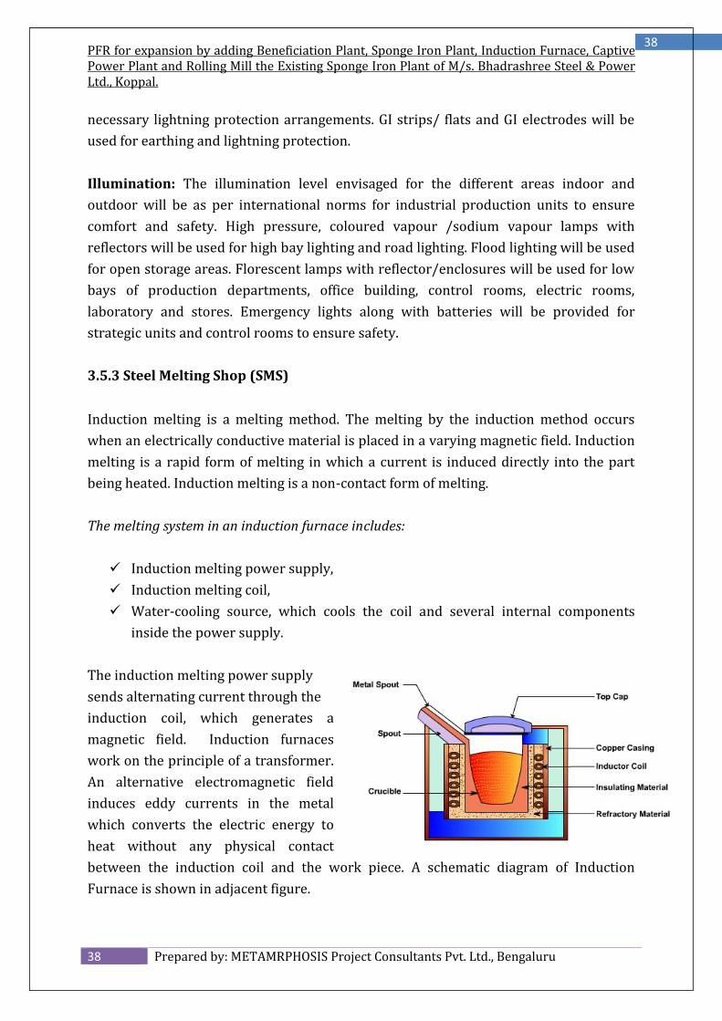
The induction melting power supplysends alternating current through theinduction coil, which generates amagnetic field. Induction furnaceswork on the principle of a transformer.An alternative electromagnetic fieldinduces eddy currents in the metalwhich converts the electric energy toheat without any physical contactbetween the induction coil and the work piece. A schematic diagram of InductionFurnace is shown in adjacent figure.
PFR for expansion by adding Beneficiation Plant, Sponge Iron Plant, Induction Furnace, CaptivePower Plant and Rolling Mill the Existing Sponge Iron Plant of M/s. Bhadrashree Steel & PowerLtd., Koppal.
The furnace contains a crucible surrounded by a water cooled copper coil. The coil iscalled primary coil to which a high frequency current is supplied. By inductionsecondary currents, called eddy currents are produced in the crucible. Hightemperature can be obtained by this method. Induction furnaces are of two types: coredfurnace and coreless furnace. Cored furnaces are used almost exclusively as holdingfurnaces. In cored furnace the electromagnetic field heats the metal between two coils.Coreless furnaces heat the metal via an external primary coil.Manufacturing Process
The process of manufacturing billets from raw materials such as Scrap, Pig Iron andSponge Iron can be broadly classified as: Melting of Raw material in Induction Furnace Working up of the molten metal to the required grade & quality of steel Casting of molten metal onto the Continuous Casting Machine
Melting of Raw-material
(a) Selection of Raw-material
The input materials for the Medium Frequency Induction Melting Furnace are spongeiron, pig iron/cast iron, scraps and consumables like ferro silicon, ferro manganese,silico manganese, aluminium shorts, etc.(b) Charging and loading of raw material into furnace
The raw materials are stored right next to the furnace for easy of operation. They areweighed in the right proportion and charged into the furnace by using an electromagnet attached to an overhead crane. This ensures lifting of sizable amount of materialwhich saves time, energy and cost. The crane used is called an E.O.T Crane. It replacesthe need and dependence on manpower.An induction furnace is the cheapest and is used in mini steel plants very economically.In an induction furnace, certain inclusions like Carbon and Ferro-alloys can be added tothe molten metal for producing good quality of steel.
PFR for expansion by adding Beneficiation Plant, Sponge Iron Plant, Induction Furnace, CaptivePower Plant and Rolling Mill the Existing Sponge Iron Plant of M/s. Bhadrashree Steel & PowerLtd., Koppal.
The process of manufacturing billets from raw materials such as sponge iron, pig ironand scrap can be broadly classified as:1. Melting of Raw material in Induction Furnace.2. Transfer of molten metal into Ladle Refining Furnace.3. Casting of molten metal onto the Continuous Casting Machine.
1. Melting of Raw-Material
(a) Selection of Raw-material
The input materials for the Medium Frequency Induction Melting Furnace are spongeiron, pig iron, scraps and consumables like ferro silicon, ferro manganese, silicomanganese, aluminium shorts, etc. To get a ton of finished product about 0.750 tonsof sponge iron, 0.200 tons of pig iron, 0.100 tons of scraps and about 0.025 tons ofconsumables are required.(b) Charging and loading of raw material into furnace
The raw materials are stored right next to the furnace for easy operation. They areweighed in the right proportion and charged into the furnace by using an electromagnet attached to an overhead crane. This ensures lifting of sizable amount of materialwhich saves time, energy and cost. The crane used is called an E.O.T Crane. It replacesthe need and dependence on manpower. For the proposed plant, 10 EOT cranes shall berequired to handle different functions besides charging of materials into the furnace; tohandle the ladles, remove the billets, etc.
PFR for expansion by adding Beneficiation Plant, Sponge Iron Plant, Induction Furnace, CaptivePower Plant and Rolling Mill the Existing Sponge Iron Plant of M/s. Bhadrashree Steel & PowerLtd., Koppal.
There are three types of furnaces that areavailable for melting of scrap into steel. Theseare - a rotary electric furnace, an electric arcfurnace and an induction furnace.A rotary furnace is mostly used for meltingpig iron and gray casting. An Electric ArcFurnace is highly competent equipment forthe purpose of steel melting. It not only canmelt efficiently but also allows time foranalysis of the molten metal and effectadjustment in the constituents of the moltenmetal. However Electric Arc Furnace is anexpensive equipment and unsuitable for small operations. This equipment is thereforeused in case of manufacturing special quality steel. It is not economical in case of ministeel plants. An induction furnace is the cheapest and is used in mini steel plants veryeconomically. In an induction furnace, certain inclusions like carbon and ferro-alloyscan be added to the molten metal for producing good quality of steel.
An induction furnace is highly sophisticated equipment consisting of a crucible with alid. The coreless induction furnace is composed of a refractory container, capable ofholding the molten bath, which is surrounded by water cooled helical coil connected toa source of alternating current. Figure shown is a simplified cross section of a corelessinduction furnace. The principle of operation of the induction furnace is the phenomenaof electro-magnetic induction. Heat is generated by the induction of medium frequencyelectricity. The induction (generation) of the electrical current in a conductive metal(charge) placed within a coil of conductor carrying electrical current is known aselectromagnetic induction of secondary current. The alternating current applied to thecoil produces a varying magnetic field which is concentrated within the helical coil. Thismagnetic field passing through the charge induces secondary current in the chargepiece. The current circulating in the charge produces electrical (I2R) losses which heatthe charge and eventually melt it. The furnace is equipped with the necessary controlpanel, which receives electrical power at normal 50 Hz frequency and converts thesame to DC power (This process is called Rectification or Conversion). The DC powergenerated is again converted to AC power (This process is called Inversion) of mediumfrequency, which induces the heating effect to the furnace. In addition to the control
PFR for expansion by adding Beneficiation Plant, Sponge Iron Plant, Induction Furnace, CaptivePower Plant and Rolling Mill the Existing Sponge Iron Plant of M/s. Bhadrashree Steel & PowerLtd., Koppal.
panel, the entire furnace system isthoroughly cooled for protection. Aseparate water supply system along withcooling tower is installed to feed thefurnace continuously with dematerializedcool water. The furnace can also be tilted topour out the molten metal. The insidesurface of the crucible is normally coatedwith castable ceramics and fire clay inintervals of 7 days. This practice protectsthe crucible and gives a longer life to thefurnace. The proposed plant shall have 2 furnaces of 12 tons of melting capacity eachper heat. Each furnace will be subjected to about 14 heats per day.d. Melting Process
The furnace crucible is charged with the requisite quantity of scrap and sponge iron andthe lid are put on. Power is introduced and the furnace gets hot and the steel starts tomelt. Heating is continued till the entire metal mass melts to liquid state. At this stage, alittle time is available for adding inclusions like ferro alloys and carbon, if necessary. Asample of molten metal is sent to the laboratories for analysis. Based on the analysisreport, ferro alloys and other alloys materials are added after proper weightment. Thetemperature of the metal bath will be adjusted suitably by adjusting power into thefurnace to ensure proper mixing of alloys in the bath. After sometime, when the metalbath has reached the appropriate temperature, sample is send to the laboratories andthe process is repeated till the desired is quality is obtained. The molten metal is nowready for pouring into the moulds.In the process of heating, the furnace crucible is charged with the requisite quantity ofsponge iron and other materials and the lid is put on. Power is introduced and thefurnace gets hot and the steel starts to melt. Heating is continued till the entire metalmass melts to liquid state. This molten metal is then poured onto ladles and carriedaway to be deposited in the Ladle Refining Furnace (LRF).2. Ladle Refining Furnace and Quality Control
Ladle Refining of liquid is a proven technology to obtain clean steel. A Ladle RefiningFurnace or LRF is a very crucial component in a continuous casting set-up as is required
PFR for expansion by adding Beneficiation Plant, Sponge Iron Plant, Induction Furnace, CaptivePower Plant and Rolling Mill the Existing Sponge Iron Plant of M/s. Bhadrashree Steel & PowerLtd., Koppal.
in this project. Regarding the ladle, it traditionally has been employed as a transfervessel, moving heats of steel weighing 20 to 350 tonnes from the Steel making furnaceto the continuous casting machine. In this project a ladle of 15 ton capacity shall beused. However, increasingly the ladle is being used as a reactor in ladle furnaces orladle-treatment stations, installed between the steelmaking furnace and the caster. Inthese operations, the composition and temperature of the steel can be adjusted to meetfinal specifications. In this way, the productivity of the steelmaking furnace can beincreased, since its primary functions are reduced to melting scrap and decarburization.A Ladle Furnace is used to relieve the primary melter of most secondary refiningoperations, and its primary functions are;
Reheating of liquid steel through electric power conducted by graphiteelectrodes. Homogenization of steel temperature and chemistry through inert gas stirring. Formation of a slag layer that protects refractory from arc damage,concentrates and transfers heat to the liquid steel, trap inclusions and metaloxides, and provide the means for desulphurization.
Secondary functions that can be included with a ladle furnace are:
Alloy additions to provide bulk or trim chemical control. Cored wire addition for trimming or morphology control. Provide a means for deep desulphurization. Provide a means for dephosphorization. Act as a buffer for down stream steelmaking equipment.
The function of the porous plug is to provide gas stirring of the molten metal to promotehomogenization. Normal stirring operations are performed by percolating argon gasthrough a purge plug arrangement in the bottom of the ladle. A top lance mechanismserves as a back up means for bath stirring in the event the plug circuit in the ladle istemporarily non-operational. The gas supply connection to the ladle is automaticallymade when the ladle is placed on the transfer car. Fumes and particulates generatedduring heating and alloying operations at the LF will exit the water-cooled ladle roofthrough the various openings in the roof. These emissions will be captured (i.e.entrained) in ambient air drawn into a lateral draft type fume collection hood mountedon supporting structures above the ladle roof. The ladle roof is typically a water-cooleddesign with a refractory center or delta section and is configured to coordinate with
PFR for expansion by adding Beneficiation Plant, Sponge Iron Plant, Induction Furnace, CaptivePower Plant and Rolling Mill the Existing Sponge Iron Plant of M/s. Bhadrashree Steel & PowerLtd., Koppal.
existing ladles such that the roof will completely cover the top portion of the ladle whenin the operating (i.e. fully lowered) position.In transferring steel from the steelmaking furnace to the caster, a major problem isoxygen absorption from the air, furnace slag and the ladle refractory lining. Thus, as thedemand for steel quality increases, steps have been taken in many operations tominimize oxygen pickup during each transfer step. Slide-gate valves have been attachedto the tap hole of the steelmaking furnace to shut off the flow of oxidized furnace slaginto the ladle at the end of the tapping operation. In some electric furnaces, the tapholehas been located eccentrically at the bottom of the furnace to facilitate the containmentof furnace slag and the attachment of a refractory pouring tube to protect the steel fromthe air during transfer into the ladle. The surface of the steel in the ladle is covered witha synthetic slag, again to prevent oxygen absorption from the air and also to absorbnonmetallic inclusions and to minimize heat losses. In some operations the ladle iscovered with a lid. Finally, when located over the casting machine, the ladle is usuallyequipped with a refractory pouring tube to prevent oxygen pickup as the steel is pouredinto the tundish. Flow of steel from the ladle to the tundish is controlled with a slide-gate valve, and in some operations the weight of the ladle is continuously measuredwith load cells.Generally, the inert gas is injected into the steel in the ladle prior to its transfer to thecaster, either to inject alloy additions or to homogenize the steel temperature. The latteris necessary because temperature control, as mentioned earlier, is vital to the control ofthe cast structure and, moreover, to the prevention of operating problems such as theformation of large skulls in the ladle and tundish if the steel is too cold, or breakouts ofmolten steel below the mold if the steel is too hot. The flow rate and duration ofinjection must be controlled since the gas discharging from the steel brings it intocontact with air unless special measures are taken.Thus, in transferring the steel from the furnace to the caster, there are opportunities tocontrol the cleanliness, composition and temperature of the molten metal. In someoperations these opportunities are not seized, so that the steel delivered to the castingmachine is dirty and too hot or too cold. Then the achievement of quality in the castproduct is a much more difficult task.
PFR for expansion by adding Beneficiation Plant, Sponge Iron Plant, Induction Furnace, CaptivePower Plant and Rolling Mill the Existing Sponge Iron Plant of M/s. Bhadrashree Steel & PowerLtd., Koppal.
In the process of steel making, the molten metal is further heated to a particulartemperature, to give it a stirring effect, so that the non-metallic parts which are lighterthat the metal float forming a slag. After controlling the composition and temperature,and removing non-metallic inclusions, the molten steel is transferred into a ladle andpoured into a mould, where it solidifies to produce semi-finished or finished products.In the past, the ingot casting and rolling (slabbing, blooming, or billeting) processeswere commonly used. In this process, the molten steel was poured into many fixed cast-iron ingot moulds and, when the solidification was complete, the ingots were taken out,reheated, and rolled by a slabbing, blooming (known as Primary Mills), or billeting mill(known as Secondary Mills). This is basically a batchprocess.The concept of continuous casting process, has nowvirtually replaced this earlier method. In continuouscasting, the molten steel in the ladle is poured into anintermediate vessel (tundish), released into a hollowwater-cooled copper mould, and continuouslywithdrawn from the bottom of the mould as a shellbegins to form around the molten metal. The reasonsfor this change include: (i) the reheating and slabbingprocess can be done away with, because the cast strand has a near-net shape similar tothat of the semi-finished product; (ii) the yield is much higher because the continuouslycast strand has only two small end portions, in contrast to the tops and bottoms whichmust be cropped from every ingot; (iii) solute element segregation and non-metallicinclusions are much lower; and (iv) advanced technologies have improved theproductivity and surface quality of the cast pieces greatly, to such an extent thatproductivity has become compatible with that of the converter and hot rollingprocesses, thus providing balanced continuity among these processes.The continuous caster allows a cast strand to be withdrawn at high speed (1.5-2.8m/min) from the mould in the form of a core of molten steel encased by a thin solidifiedshell. This high withdrawal speed ensures that casting productivity is matched to that ofthe converter. As the cast strand descends from the mould, its surface is cooled by awater spray or water mist, and the thickness of the shell increases progressively as thematerial solidifies. However, the ferrostatic pressure of the molten steel rises at thesame time. The cast strand is therefore supported by rolls so that the solidified shell
PFR for expansion by adding Beneficiation Plant, Sponge Iron Plant, Induction Furnace, CaptivePower Plant and Rolling Mill the Existing Sponge Iron Plant of M/s. Bhadrashree Steel & PowerLtd., Koppal.
does not bulge. If the solidified shell is deformed due to thermal strains or ferrostaticpressure, cracks form on both the surface and in the interior due to the low ductility andlow strength of the shell at high temperatures. An analysis of heat transfer between themolten steel/solidified shell/mould or spray is necessary to increase productivity andprevent deformation and cracking. In addition to this analysis, it is imperative toanalyse stress, strain, and deformation in the solidified shell when it passes throughboth the mould and the support rolls. Progress has been made in the analyses of theheat transfer, elastic-plastic thermal stress, and creep-behaviour of the cast strand byuse of the finite difference and finite element method, and various computationalprograms simulating these phenomena have been developed. The measurement of thedynamic behavior of steel at elevated temperatures necessary for such computationshas also been carried out.The continuous caster is composed of a tundish, a mould, a mould oscillator, a group ofcast-strand supporting rolls, rolls for bending and straightening the cast strand, rolls topinch and withdraw the cast strands, a group of spray nozzles, a torch cutter for cuttingthe cast strand, a dummy bar for extracting the cast strand at the start of casting, andother components. The continuous billet caster casts round or square strands of smallcross-section, and the continuous bloom caster casts strands of large cross-section. Bothare used to produce materials for long products such as wire rod, bars, shapes, andpipes. The continuous slab caster produces wide rectangular strands of large cross-section, which are cut off as slabs for use as material for flat products such as sheet andplate. Slabs for flat-rolled products are usually cast with a thickness of 100 to 250mm. Inrecent years, however, continuous casters which produce thinner slabs 30-80mm inthickness have been introduced. The thin slab caster eliminates the need for a roughingmill in the hot-rolling process. However, the steel throughput is limited to 1 millionton/year per strand in this process by the thin slab thickness even at higher castingspeed, which is currently limited to about 7m/min. Consequently, the thin slab caster isusually combined with an electric furnace of matching output. This combination hasbeen favorably adopted by mini steel plants.The types of continuous casters include: (i) the vertical type, in which the mould andsupport rolls are arranged vertically; (ii) the vertical-and-bending type, in which thesolid shell of the cast strand is bent in the horizontal direction at the position wheresolidification is sufficiently complete; (iii) the curved type, in which a curved mould andsupport rolls are arranged on an arc of the same radius, and the cast strand isstraightened horizontally at the end of solidification; (iv) the vertical-and-
PFR for expansion by adding Beneficiation Plant, Sponge Iron Plant, Induction Furnace, CaptivePower Plant and Rolling Mill the Existing Sponge Iron Plant of M/s. Bhadrashree Steel & PowerLtd., Koppal.
progressive-bending type, in which the mould and a group of upper support rolls arearranged vertically and the cast strand still with a liquid core is progressively bent, andthen progressively straightened to the horizontal position at the end of solidification;and (v) the horizontal type, in which the mould and support rolls are arrangedhorizontally. The vertical type is used to cast high-grade steels because it promotes theseparation (by flotation) of nonmetallic inclusions poured into the mould, although theconstruction of the caster building becomes tall and hence expensive. The curved type ismainly applied for mass production of conventional products, because building costscan be reduced by the lower height. The vertical-and-progressive-bending type, whichcombines the advantages of the vertical and curved types, is being used increasingly forlarge sized slab casters which require improved quality and productivity. The horizontaltype is used to produce billets on a small scale because the equipment and the buildingcosts are comparatively low.The productivity and yield that are so important for operating a continuous caster canbe markedly improved by casting many heats continuously without interruptingcasting. This is called continuous-continuous casting or sequence casting, and has theadvantage of eliminating the need for preparations for starting the casting over andover again. Consequently, productivity is increased and the amount of the cast strandwhich must be cropped at the initial and final casting positions due to poor quality isdecreased. Techniques have been developed for sequence casting, which allow themould width to be changed and different steel grades to be cast without interruptingcasting operations. These allow more than one strand of different width and grade to becast continuously without interruption.The sequence of the casting operation starts with inserting the dummy bar into themould to seal the bottom end. Molten steel is then poured into the mould from thetundish while taking great care to prevent contact with the air. The withdrawal of thecast strand is started by pulling the dummy bar downward. The molten steel flowinginto the mould is rapidly cooled and forms a thin solidified shell composed of finegranular crystals on the surface and an array of fine columnar dendrites inside. Thesolidified shell becomes thicker due to the growth of columnar dendrites as it descendsthrough the mould. A lime silicate flux is added to the molten steel surface in the mouldto prevent heat loss from the molten steel surface and absorb non-metallic inclusions asthey surface. This flux also infiltrates between the mould and the cast strand, andprovides lubrication which also prevents sticking of the cast strand to the mould duringthe oscillation of the mould. At the same time, the layer of mould flux between the steel
PFR for expansion by adding Beneficiation Plant, Sponge Iron Plant, Induction Furnace, CaptivePower Plant and Rolling Mill the Existing Sponge Iron Plant of M/s. Bhadrashree Steel & PowerLtd., Koppal.
and mould reduces heat transfer and avoids a rapid decrease in the temperature andresulting deformation and crack formation of the strand.Surface defects are formed on the cast strand when the level of the steel bath fluctuatesin the mould. The level is therefore measured with a sensor and kept as constant aspossible by controlling the flow rate of molten steel from the tundish. Electromagneticbraking of the melt flow in the mould is now a representative technique for meniscuslevel control. The cast strand, which still contains unsolidified molten steel, exits themould and is withdrawn downward while being supported by a group of rolls andwater-cooled with the sprays. During this process, columnar dendrites continue togrow, and equiaxed dendrites are finally formed to complete solidification. At this time,the solidified shell is subjected to high thermal strain, shrinkage, and transformationcaused by cooling, and to ferrostatic pressure. Since the hot solidified shell issubstantially lower in strength and toughness, the cast strand is susceptible to surfaceand internal cracks. Consequently, during spraying the cooling pattern is carefullycontrolled to prevent the growth of cracks due to strain while ensuring solidification bycooling. This pattern control involves controlling the intensity of the water-mist sprayalong the width wise and drawing direction of the cast strand as required by the steelgrade. Reduction is then applied to the cast strand at the crater bottom to reduce centresegregation. After cutting to length with gas torches, the cast piece, or slab, is deliveredto the hot-rolling process.Casting Process: Liquid steel taken into ladle is refined at LF is placed over the turretarm and ladle SG is fixed. Then one shroud is fixed at the bottom of the ladle collectornozzle so that no stream of liquid steel comes in contact with the atmosphere and nospillage occurs. This liquid steel gradually fills the tundish and from there liquid steelleaves tundish nozzle through SEN into the mould. Initially steel rests on the DUMMYBAR head on which some chillers are placed to get the liquid steel freeze/solidifiesquickly then the m/c starts & casting powder is to be sprayed continuously at a certainmould level. The process continues after the DUMMY BAR head is disconnected as itreaches at its particular position. Length of the slab/billet is maintained by using cuttingtorch/ shearing blades.Schematic of Induction Furnace Process: Conceptual Scheme of Induction FurnaceProcess arrived at by the Company based on Test Results on Samples.
PFR for expansion by adding Beneficiation Plant, Sponge Iron Plant, Induction Furnace, CaptivePower Plant and Rolling Mill the Existing Sponge Iron Plant of M/s. Bhadrashree Steel & PowerLtd., Koppal.
Continuous Casting of Billet: Continuous casting has emerged as a tool for increasingproductivity and improving quality of billets in the steel industries over the past decade.The main advantages associated with continuous casting process are: Improved yield by 10% to 12% and reduced the production cost by over 20%over the conventional ingot-casting route. Less manpower due to fewer production steps in the way from molten metal tofinished product. Possibility of fully continuous and highly automated operation.Because of these inherent merits, the popularity of CC is steadily rising alongwith improvements in product quality and leading to find application in areas,which were earlier reserved for ingot casting.
Billet sections are the most widely used primary material in the production of ultra-clean, high strength carbon wire, special forgings, cutting-edge automo-tive engineeringsteel, ball-bearing steel and stainless steel products. The high quality of Billetssproduced using SMS Concast Billet casters ensures fine steel products with the very bestproperties. The same applies if the final products have large dimensions, such as axlesfor trucks, crankshafts, springs, rails, or power-generation shafts. Rectangular Billetsections can be up to 600 mm in width and up to 450 mm in height. Billet casters can bebuilt with up to eight strands and a typical machine radius of between 10 and 18 m, oreven as fully vertical casters.
PFR for expansion by adding Beneficiation Plant, Sponge Iron Plant, Induction Furnace, CaptivePower Plant and Rolling Mill the Existing Sponge Iron Plant of M/s. Bhadrashree Steel & PowerLtd., Koppal.
Round Billets feature the most homogeneous cross section in terms of both temperaturedistribution and internal structure. As with rectangular Billets, round Billet casters canbe designed for up to eight strands. SMS Concast supplies curved casters for roundBillets with a diameter of up to 1000 mm.Process Description
The molten metal obtained from above process is taken in refractory lined metal ladle.After undergoing any ladle treatment, such as “S” removal and gentle stirring withnitrogen or argon gases to degassing, removing inclusions and alloying, the ladle isshifted to the top of the casting machine. Usually, one or more ladles sit in the slots in arotating turret on top of the casting machine; one ladle is casting while the others aremade ready, and are switched to the casting position once the first ladle is empty.From the ladle, the hot molten metal is transferred via a refractory shroud to a holdingvessel called tundish. The tundish allows a reservoir of metal to feed continuously thecasting machine and also acting as a buffer of hot metal while ladles are switched, aswell as smoothing out flow, regulating metal feed to the mould and cleaning the metal.Liquid steel is poured from the tundish through another nozzle into water cooled andvertically oscillating copper mould tubes and continuously withdrawn from the bottomof the mould at the casting speed. The liquid steel in mould is generally controlled bymetering nozzle or stopper rod in the tundish or through slide gate system Castingpowder or rapeseed oil also added on the top of the metal in the mould to preventsticking and to trap any slag particles, oxides, scale etc.In the forced water cooled mould the metal layer next to the mould walls solidifiesbefore the central portion of the metal, (here after called strand) exits the base of thecurved mould into a spray chamber. In this stage the bulk of the metal within thesolidified shell of the strand is still molten. The exiting strand is immediately supportedby closely spaced foot rolls and large quantity of water is sprayed on the stranduniformly from all four sides to increase the rate of cooling and solidification of thestrand.In the spray chamber, the covered exiting strand from the mould is guided to horizontalposition by the support rollers in the spray chamber. The strand then passes throughthe straightening and withdrawal rollers. The strands are as such taken to the coolingbed through a battery of rollers after cut into predetermined lengths by mechanicalshearing or by traveling oxyacetylene torch and pushed on the rails in the cooling bed
PFR for expansion by adding Beneficiation Plant, Sponge Iron Plant, Induction Furnace, CaptivePower Plant and Rolling Mill the Existing Sponge Iron Plant of M/s. Bhadrashree Steel & PowerLtd., Koppal.
by the pushers and allowed to cool. Later it is marked for identification and then sent tostockpile or to the next forming process.Steel pertaining to specific grades is melted in suitable furnace, and then tapped in to aladle. The ladle is lifted up by EOT crane and brought to the casting platform and placedon the ladle platform. Bellow the ladle tundish properly lined with refractory bricks andadequately suited nozzle is placed on a tundish car which can be moved on rail. Theposition of the tundish nozzle is aligned with respect to the mould in such a way that theliquid steel falls directly into the mould. The bottom of the mould is plugged withdummy bar head, whose tail end passes through the withdrawal rollers. The mouldassembly consists of four mould plates of which three sides are adjustable.The oscillation is necessary to prevent molten metal sticking on to the wall duringcasting.At the start of casting the withdrawal rollers move and dummy bar gradually brings theSolidified portion of the cast slab out of the mould while metal stream falls in to themould constantly. The slab follows the curved path over a strand carrier consisting offive segments each possessing paired rollers on the outer and inner surface of the slab.The slab is constantly sprayed by water through-out the length of the apron throughspray nozzles. Soon after the dummy bar head with the meta solidified on it comes outof the withdrawal, a dummy bar disconnecting device detaches the slab end from thedummy bar head. The dummy link rolls on to a cage shifts it paving way for the slab. Theslab passes over the series of rolls arranged up to the end of the skid rails. The slab iscut manually or by auto cutter (Optional) in to required length and the slab reaching theend of the skid rails is pushed on the rail by action of the pusher.In this way liquid metal is cast continuously in to slabs and are cut in to required lengthand stored on the skid rails till the ladle and tundush becomes empty casting comes toan end.3.5.5 Rolling Mill
Rolling is one of the most important industrial metal forming operations. Hot Rolling isemployed for breaking solid into wrought products such as Billet blooms and slabswhich are subsequently, rolled to produce Bars, channels, angles, beams and plates.
PFR for expansion by adding Beneficiation Plant, Sponge Iron Plant, Induction Furnace, CaptivePower Plant and Rolling Mill the Existing Sponge Iron Plant of M/s. Bhadrashree Steel & PowerLtd., Koppal.
Rolling is the plastic deformation of materials caused by compressive force appliedthrough a set of rolls. The cross section of the work piece is reduced by the process. Thematerial gets squeezed between a pair of rolls, as a result of which the thickness getsreduced and the length gets increased.Then adequately heated solid pieces are introduced in to rolling mill stands in which anumber of carbon steel and chilled steel rolls works successfully, The hot metal ispassed through number of rolls which are run with the help of a motor and fly wheeland the sizes gradually decreases and after passing through last stand the requiredrolled size is obtained. Products of desired cross section can be obtained by adjustingthe roll passes and designs the desired shape of the product is obtained from the last offinishing rods.While hot rolling produces is on, continuous cooling water from the water tank ispumped out and by special jets is poured between the rolls by which the rolls getstrengthen and also life gets increased. After the final passing the finished product willbe kept over the cooling bed for the cooling process. The cooling of the hot rolledproducts is normally done on a cooling bed which is nothing but a simple platform opento the atmosphere.The proposed rolling mill in this project shall be produced with different final productsin the form of TMT Bars. The TMT Rolling process in which rolling is done above re-crystallization temperature. It is called TMT Hot Rolling procedure.The TMT basic process shall be basically classified into following heads:-
A. Re-HeatingB. RoughingC. Intermediate RollingD. Finished Shape RollingE. Cutting & StampingF. FinishingG. InspectionH. DispatchA) Re-Heating: The Re-heating of input is done to make the material basicallydeformable pliable for rolling to give the desire shape and size. It is done such that therolling gets completed above re-crystallization temperature.
PFR for expansion by adding Beneficiation Plant, Sponge Iron Plant, Induction Furnace, CaptivePower Plant and Rolling Mill the Existing Sponge Iron Plant of M/s. Bhadrashree Steel & PowerLtd., Koppal.
B) Roughing: Roughing is also called Cogging is done to give the input a rough shape.The maximum reduction is cross section is given in roughing mill.C) Intermediate Rolling: Intermediate rolling takes the roughing mill output as itsinput. Output of the intermediate rolling is sent to finishing Mill.D) Finished shape rolling: In furnace Mill the finished profile shape is made. It takesmetal from intermediate stands as its input, the reduction given in this stands is lessercompared to roughing and intermediate mill. Finished shape rolling is Quality critical asthe final out put shape is made in theses stands. In case of TMT bars thermosmechanical treatment of the bars is done in this area.E) Cutting and Stamping: The finished bar is cut to desire length as per customerrequirement. Other activities performed here are cropping of ends, cutting of samplesfor profile dimensional checking and cutting of samples for destructive tests.F) Finishing: The finishing is done after the bar has been cooled to ambienttemperature finishing activities at different mills may involve following steps:- End finishing either by milling or cold cutting. Non-line non-destructive of defects. Bundling is to be done according to the requirements.
G) Inspection: Inspection is carried out by the Quality control in house/third party toinspect the product and ensure no defective products are available. Depending on thespecifications and customers’ requirements the inspection is done in all or few of thefollowing parameters:- Dimensional tolerance Length Straightness Surface qualities Branding, colour coding and stamping
H) Dispatch: The products are sent to the required destinations primarily by rail androad. Being as the final product the dispatch activities involves documentation likeinvoices, test certificates, clearances etc.
PFR for expansion by adding Beneficiation Plant, Sponge Iron Plant, Induction Furnace, CaptivePower Plant and Rolling Mill the Existing Sponge Iron Plant of M/s. Bhadrashree Steel & PowerLtd., Koppal.
Re-heating Furnace Stands Accessories of Stands Drives Shears/Cutting saws Straightening Machines End finishing equipment Online testing equipment Auxiliaries
Equipment Descriptions
a) Reheating furnaces: The heating of inputs is done in reheating furnaces. In theintegrated steel plants the fuel used is primarily a mixture of coke oven and blastfurnace gases Primary long product mills use batch type furnaces (Soaking pits) forreheating of ingots. Finishing mills use continuous furnaces (either pusher type orwalking beam type) for reheating of inputs.
FurnaceRoughing Mill
Intermediate MillFinishing MillTMT ProcessCooling Bed
Automatic Bund / Bind / M/C
PFR for expansion by adding Beneficiation Plant, Sponge Iron Plant, Induction Furnace, CaptivePower Plant and Rolling Mill the Existing Sponge Iron Plant of M/s. Bhadrashree Steel & PowerLtd., Koppal.
b) Stands: Equipment in which rolling is done are called stands. They may consist of allor few of the following components. – Rolls, housings, bearings, chocks, couplings withdrives, manipulators, tilters, screw down mechanisms. The stand may have horizontalrolls or 89 vertical rolls or combination of both types of rolls. In some cases descaling ofbar is done for scale removal to obtain better surface finish.c) Accessories of stands: Accessories of stands consist of mainly roll coolingarrangements, guards, guides, tackles and grease systems etc. Guards strip the rolledbar of the roll and avoid its wrapping around the rolls. Guides guide the bar into and outof the passes. Water cooling of passes, rolls, bearings is very important in hot rolling toavoid roll breakages, bearing failures and reduce roll wear out.d) Drives: In most of the mills reversible electrical drives of high ratings are required todrive the rolls. In certain cases the drives give their output directly to rolls throughspindles. In other cases when multiple rolls are driven by a single motor thetransmission of torque to rolls may be through a pinion stand and spindles.e) Shears / Cutting Saws: Shears are used to cut heavier sections (Blooms/Billets) inprimary mills. Cutting saws are used to cut products of finishing mill to desired lengths,cut crops and samples.f) Straightening machines: Two types of straightening machines are in use in finishingmills. Roller type in which the products are straightened by alternately bending theproducts in opposite directions between rotating rollers as exhibited in figure. In case oflighter profiles the straightening is done by pulling from both the ends.g) End finishing equipment: Ends with square cut and good surface finish required insome finished products is achieved by milling or cold cutting with carbide saws.h) Online testing equipment: In some finished products online nondestructive testingis done by ultrasonic testing machine (for inside defects) and eddy current testingmachine (for surface defects)I) Auxiliaries: Auxiliaries such as cranes, roll tables, material handling equipment etc.,are very important for integrated functioning of mill.
PFR for expansion by adding Beneficiation Plant, Sponge Iron Plant, Induction Furnace, CaptivePower Plant and Rolling Mill the Existing Sponge Iron Plant of M/s. Bhadrashree Steel & PowerLtd., Koppal.
Under thermos-mechanical treatment, the steel bars are passed through a speciallydesigned water-cooling system where they are kept till the outer surface of the barsbecomes colder while the core remains hot. This creates a temperature gradient in thebars. After the intensive cooling, the bar is exposed to air and the core re-heats thequenched surface layer by conduction, therefore tempering the external marten site.When the bars are taken out of the cooling system, the heat flows from the core to theouter surface, further tempering of the bars, which helps them attain higher yieldstrength. The resulting heat-treated structure imparts superior strength and toughnessto the bars.The pre-determined cooling of the bar periphery transforms the peripheral structure tomarten site and then annealed through the heat available at the core. The peripheraland core temperature difference finally equalizes at around 600°C and the resultant barstructure is of tempered marten site at the periphery and of fine-grained ferrite-pearliteat the core. Generally speaking, the resultant soft core forms about 65-75 per cent of thearea (depending upon the desired minimum yield strength) and the rest is the hardenedperiphery. The equalizing temperature together with the final rolling temperature is themost important parameter to achieve the required mechanical properties. Finally, when
PFR for expansion by adding Beneficiation Plant, Sponge Iron Plant, Induction Furnace, CaptivePower Plant and Rolling Mill the Existing Sponge Iron Plant of M/s. Bhadrashree Steel & PowerLtd., Koppal.
the bar is discharged on to the Cooling Beds, the remaining austenite transforms into avery fine-grained pearlite structure.3.5.6 Captive Power Plant
1. Technical Features
Fluidized bed boilers are designed on the basic principle that when air is allowed toflow through a bed filled with fine grains at low velocity, the solid matter remains in astate of rest. As the velocity of the air is increased the pressure losses rise by the squaretill a state is reached wherein pressure losses do not rise with further increase invelocity. At this stage the bed is characterized by high turbulence with high mass andheat transfer co-efficient. The grains are held in partial suspension and thischaracteristic makes the “fluidized bed” perform many functions simultaneously.Fluidised bed works as: Combustion chamber, where carbon is changed into carbon monoxide andcarbon dioxide. Heat exchanger in which the heat is transferred to furnace and the bed tubes.
A. Power Cycle Configuration
In the conventional steam system operating on Rankine cycle, the main equipments arethe steam generator, steam turbine and the condenser with their auxiliaries. The utilitysystem includes fuel handling, plant water, fire water, compressed air systems etc. thefollowing factors have influenced the selection of major equipments: The efficiency of steam power cycle improves with the increase in the inlet steamtemperature and pressure, as has been established by thermodynamics. The basic power cycle configuration chosen for the 15 MW would be withpressure of 64 ATM and temperature of 490±5° C at turbine inlet The proposed power plant is intended to be operated as a base load plant withhigh availability.
PFR for expansion by adding Beneficiation Plant, Sponge Iron Plant, Induction Furnace, CaptivePower Plant and Rolling Mill the Existing Sponge Iron Plant of M/s. Bhadrashree Steel & PowerLtd., Koppal.
Boiler: The selected configuration would consist of one (1) no. FBC boiler with amaximum continuous rating of 60 TPH and (4) Nos. of WHR Boilers connected to asingle turbo-generator of 15 MW nominal capacities.Turbine: In order to optimize the cycle efficiency, the concept of regenerative feedheating is adopted. The 15 MW size turbines are having axial length of approx. 7 meters.Hence it shall be possible to provide One (1) no. of steam tap off nozzles in the turbinefor feed heating making the turbine a single extraction cum condensing type.Following aspects are considered while selecting the type of fuel firing system:
The boiler type and size are to be chosen considering the fact that the Coalquality. The combustion method to be adopted with respect to the type of fuel to be fired. Economy of installation and operation.
2. Selection RecommendationsBased on the above, following configurations shall be adopted:Steam Generators
A No. and ratings One (1) no. 60 TPHB Type of Boiler Atmospheric Fluidised Bed Combustion (AFBC)C No. of boiler fans 1 x 100 % for ID, FD & 2 x 100% PA fanD Type of pollution control system Electro static precipitator (ESP)WHRB
A No. and ratings Four (4) no. 10 TPHB Type of Boiler Waste Heat Recovery Boiler (WHRB)C No. of boiler fans 4 x 100 % for IDD Type of pollution control system Electro static precipitator (ESP)
PFR for expansion by adding Beneficiation Plant, Sponge Iron Plant, Induction Furnace, CaptivePower Plant and Rolling Mill the Existing Sponge Iron Plant of M/s. Bhadrashree Steel & PowerLtd., Koppal.
A No. and ratings 1 no. of inlet parameters 64 ATA & 490±5°CB Capacity (rated) 15 MW Maximum continuous ratingC Capacity (VWO Condition) 15.5 MWD No. of controlled extractions One (1)E Type of Exhaust steam cooling Air Cooled Condenser (ACC)Steam GeneratorsAtmospheric Fluidized Bed Combustion Boiler
The steam generator will be atmospheric fluidized bed, outdoor, natural circulation andbalanced draft type with direct crushed coal firing. The steam generator unit will besized for about 60 TPH steam flow at 67 ata steam pressure and 495±5 Deg C steamtemperature at MCR with design Indian Coal. This will ensure adequate margin over therequirement of turbine at 100% MCR to cater for.The steam generator design parameters shall be as follows:
I Maximum continuous rating (MCR)(T/hr) 60II Peak capacity of the boiler as a percentage of MCR capacity % 110%III Super-heater outlet pressure [ATA] 67IV Super-heater outlet temperature (°C) 495±5V Feed water inlet temperature (°C) 126VI Excess air (%) Not more than 20VII Boiler outlet flue gas temperature (°C) 100 (max.)VIII Dust concentration at chimney (mg/Nm3) <50 (max)The boiler shall be formed of by water cooled, gas tight fin welded/membrane wallswith refractory lining up to the end of free board. The lower section of the first boilerpass consists of the combustion chamber with the fluidized bend and free board above,while the upper section is made up of a convection pass with part of the heatingsurfaces.The boiler shall be capable of operating with an output 110% of the MCR rating for aperiod of 30 minutes in each of an Eight (8) hour shift. All components and equipmentof the boiler shall be designed to operate under this peaking load requirement withoutany design or operational limitation.
PFR for expansion by adding Beneficiation Plant, Sponge Iron Plant, Induction Furnace, CaptivePower Plant and Rolling Mill the Existing Sponge Iron Plant of M/s. Bhadrashree Steel & PowerLtd., Koppal.
The boiler shall be designed for fully automated operation from the distributed controlsystem from the central control room. Most of the valves required to be operatedduring the starting or the normal running of the boiler shall be with electrical motoractuators. The start-up of the boiler shall be with LDO firing and suitable burners shallbe provided for start up. The boiler shall be basically designed for under bed feeding ofIndian Coal and char.Steam drums: Furnace water wall & Bed Evaporator system and superheated system &Re-heater system including headers and Connecting pipesEconomizer system: Together with all required headers, integral piping,interconnecting piping, valves, fittings, supports, etc. shall be provided.The circulating system essentially comprising of the drums, water walls, furnace tubes,in-bed evaporator tubes, down comers and relief tubes shall be designed to provide anadequate circulation ratio in the system. The down comers and the relief tubes shall besized and routed to offer minimum pressure drop and to aid the improvement in thecirculation ratio. The sizing of the circulation system components shall be adequate toensure safe circulation ratios even under peak loading conditions.Steam Drum: The boiler shall be provided with steam drum of fusion welded type. Thesteam drum shall be liberally sized to assure low steam space loading with adequatespace to accommodate the internals. The drum design pressure shall have a minimummargin of 6% over drum operating pressure.Furnace Water Wall and In-Bed Evaporation System: The Furnace envelope shall beconstructed of fully water-cooled membrane/fin welded walls and adequatelysupported. The design shall be such as to prevent distortion of steel work due tothermal expansion.The Combustor area of the furnace shall also be of membrane wall/fin welded wallconstruction with refractory lining on the inside perimeter, for a height more than theexpanded bed height. The spacing and arrangement of the bed evaporator coils,preferably with an in-line arrangement, shall be optimized to minimize high localvelocities and to avoid erosion. The arrangement of the in-bed coils shall also take intoconsideration the removal of clinkers in the event of clinker formation. The in-bed tubesshall be given adequate protection against erosion by high density stud welding on thetubes both on the straight and bend portions of the tubes. The water wall panel fin
PFR for expansion by adding Beneficiation Plant, Sponge Iron Plant, Induction Furnace, CaptivePower Plant and Rolling Mill the Existing Sponge Iron Plant of M/s. Bhadrashree Steel & PowerLtd., Koppal.
thickness and width shall be such that the fin tip to base temperature differential doesnot exceed 70 Deg C.Super heater System: The super heater (SH) system shall be of two (2) stage designwith inter stage de-superheating to achieve the rated steam temperature over 60% to100% load range. The super heater shall be of convection or a combination ofconvection and radiation type or a combination of convection and in-bed type. Thesuper heater pressure drop, the inlet and outlet header sizing, arrangement and sizingof their respective inlet and take off connections shall be so as to give minimumunbalance and the tube element material selection shall be based on the actual metaltemperature calculations.Attemperator System: The attemperator system, to control the temperature of thefinal superheater outlet steam temperature, within the specified value, shall beprovided in between the two stages of the superheaters. The interstage attemperatorshall be of the spray type, using the boiler feed water tapped off at the outlet of theboiler feed water pumps, to control the final steam temperature between 60% to 100%MCR load.Economizer: The Economizer shall be located in the second pass of boiler. The designshall be of bare tube construction with inline, counter flow, and drainable arrangement.The economizer shall be designed for an inlet feed water temperature of 126 Deg C. Theeconomizer shall be arranged such that there is space for the future addition of about15% of the installed heating surface area without disturbing the existing economizercoils. The coil arrangement shall take care of proper calculated end gaps to avert pasbypassing and the consequent erosion of the element tubes. No gas side or water sidebypass arrangement shall be provided.Air Heater: The air heater shall be arranged as the last heat recovery sectiondownstream of the economiser. The Airheater shall be recuperative type with flue gasflowing inside the tubes and the combustion air flowing over the tubes. The airheatershall be arranged with the tubes in the vertical direction. The inner diameter of thetubes shall be a minimum of 50 mm and the minimum thickness of the tube shall be 2.2mm. The tubes except those required for staying purposes shall be expanded into thetube sheets on both ends.Fuel Feeding System: The fuel feeding system shall facilitate smooth, easy and metereddistribution of the fuel into the Atmospheric fluidized bed combustor. The layout of the
PFR for expansion by adding Beneficiation Plant, Sponge Iron Plant, Induction Furnace, CaptivePower Plant and Rolling Mill the Existing Sponge Iron Plant of M/s. Bhadrashree Steel & PowerLtd., Koppal.
fuel feeding system shall be such that each system is easily approachable andmaintainable.The fuel storage bunker of rectangular cross section with adequate capacity to hold theIndian Coal & Dolo Char requirement of 16 hours of maximum continuous rating of theboiler shall be provided in front of the boiler. Prepared fuels from the crusher housewill be delivered to the bunker through a tripper conveyor.The feeders shall be of either air lock rotary type or drag chain type and shall be ofproven design. The number of feeders shall depend on the capacity of each of thefeeders, the number of fuel feed points to the combustor and the branching and routingof the fuel pipes from the feeders to the feed nozzles. However there shall be aminimum of three feeders each with a capacity each of a minimum of 40% of the MCRrequirement.Draft System: The draft system for the boiler shall be suitable of producing a balanceddraft with sub atmospheric pressure conditions in the furnace. There shall be 1 x 100%capacity Induced Draft Fan, 1 x 100% Forced Draft Fan and 2 x 100 % capacity Primary AirFan making up the complete draft system for the boiler. The fans shall be basically sizedusing adequate margins over the calculated values of the flow volume and the pressureusing the maximum continuous rating condition.Ducting System: All ducts shall be rectangular in cross section and will be of weldedconstruction properly stiffened and reinforced. All the air ducts shall be fabricated fromsteel plates of minimum 4 mm thick and all flue ducts shall be of minimum 6 mm thick.The duct plate material shall conform to IS 226 / IS 2062. Carbon steel plates shall notbe used for ducting system if the operating temperature of flue gas exceeds 425°C. Theduct corners shall be stitch welded internally and full welded on the outside.Boiler Start up System: The boiler shall be started from the start up compartmentusing the hot gas supplied to the start up compartment. The start up system include theduct mounted LDO burner system, located in the fluidizing air supply duct to the startup compartment, the internally lined ducting leading the hot gases to the start upcompartment wind box, oil storage day tank, oil piping, valves, control valves, tripvalves, instrumentation and controls suitable for operation from the DCS etc. Theburners system shall consist of the air atomized oil burner, electric arc ignitor, burnermanagement system etc.
PFR for expansion by adding Beneficiation Plant, Sponge Iron Plant, Induction Furnace, CaptivePower Plant and Rolling Mill the Existing Sponge Iron Plant of M/s. Bhadrashree Steel & PowerLtd., Koppal.
Chemical Dosing System: The boiler shall be provided with a common tri-sodiumphosphate based High Pressure (HP) dosing system and a hydrazine and ammoniabased Low Pressure (LP) dosing system. The HP dosing system shall add the chemicalto the boiler water to take care of the ingress of the hardness salts and to increase theboiler water pH. The LP dosing is done to the feed water preferably at the outlet of thedeaerator to scavenge the last traces of oxygen and to increase the feed water pH. HPdosing system sizing shall be with one percent (1%) concentration of tri-sodium-phosphate.Blow Down Tank: One continuous blow down (CBD) tank and one intermittent blowdown tank (IBD) shall be provided for the boiler. The flash steam from the CBD tankoutlet shall be piped to the deaerator and the outlet of the IBD tank shall be vented toatmosphere. The level control system and the safety valve for the CBD tank, requiredsupports, drain valves, level gauges, and necessary piping etc., for both CBD and IBDtanks shall be provided.A) Waste Heat Recovery Boilers
The WHRB shall be sized and designed to extract maximum sensible heat energycontained in the waste gases emanating from the Direct Reduction kiln. The majortechnical parameters of WHRB are given below:Technical features of Steam Generator (WHRB)
The steam generator consists of membrane type Radiant chamber, superheater,evaporator and economizer. Pressure Parts The complete system of boiler pressure parts, covering: Steam drums Water wall / radiant chamber Evaporator Superheater Economizer Together with all required headers, integral piping, interconnection piping,valves, fittings, supports, etc. will be provided.
The circulating system essentially comprising of the drums, water walls, etc will bedesigned to provide an adequate circulation ratio. The sizings of the circulation system
PFR for expansion by adding Beneficiation Plant, Sponge Iron Plant, Induction Furnace, CaptivePower Plant and Rolling Mill the Existing Sponge Iron Plant of M/s. Bhadrashree Steel & PowerLtd., Koppal.
components will beadequate to ensure safe circulation ratios even under peak loadingconditions.Steam Drum: The boiler will be provided with steam drum of fusion-welded type. Thesteam drum will be liberally sized to assure low steam space loading with adequatespace to accommodate the internals. The drum design pressure will have a minimummargin of 6% over drum operating pressure.The steam drum will be provided with internals of proven design, will be bolted type,and of size that will enable removal through the man ways.Evaporator: Evaporator section has horizontal, inclined, inline type arrangement withtop and bottom headers for easy flow of steam water mixture. It is connected to thesteam drum through adequately sized down comers and risers.Economiser: The design will be of bare tube construction with inline, counter flow, anddrainable arrangement. The coil arrangement will take care of proper calculated endgaps to avert bypassing and the consequent erosion of the element tubes. No gas side orwaterside bypass arrangement will be provided.Gas Circuit: Waste gases from Post combustion Chamber of Kiln enters the radiantchamber, then gas passes through the superheater section, evaporator and economizersection. From economizer section it goes to ESP. There will be one (1) x100% capacityInduced Draught Fan per Boiler, which will draw the cooled exhaust gas and sends toChimney.Common Blow down Tank: One blow down tank will be provided for the boiler. Theflash steam from the tank will be piped to the deaerator and the outlet of the tank willbe vented to atmosphere. The level control system and the safety valve for the tank,required supports, drain valves, level gauges, and necessary piping etc., for tank will beprovided.b) Steam Turbine Generator Unit
Steam Turbine: This project envisages one (1) no.15 MW extraction- cum- condensingturbo-generator. The turbine shall be designed for the operation with the inlet steamparameters at 64 ata and 490 C and shall be with automatic controlled extraction steam.
PFR for expansion by adding Beneficiation Plant, Sponge Iron Plant, Induction Furnace, CaptivePower Plant and Rolling Mill the Existing Sponge Iron Plant of M/s. Bhadrashree Steel & PowerLtd., Koppal.
The turbine shall be horizontal, single extraction-cum-condensing type for 15 MW. Allcasings and stator blade carriers shall be horizontally split.The low pressure casing shall have a bottom exhaust arrangement configuration and theexhaust casing shall be suitable for connection to the air cooled condenser without airleakage and suitable for maintaining the condenser vacuum. The turbine exhaust hoodshall be provided with exhaust water spray system to protect the turbine againstexcessive temperature due to windage at no load and low load conditions.Gland Sealing System: The glands shall preferably be of labyrinth type and sealed withsteam. The gland packing shall be of 13% chromium stainless steel. The labyrinthsshall be of multi-section spring backed type which would allow for any temporarydeformation of the rotor shaft without overheating the rotor due to friction. The glandsealing system design shall permit the examination of and replacement, if necessary, ofthe glands without lifting the upper half of the turbine casing.Bearings: The turbine shall be provided with liberally rated hydrodynamic radial andthrust bearings. The radial bearings shall be split for ease of assembly and of the sleeveor pad type, with steel shell backed, babbitted replaceable pads. These bearings shall beequipped with anti-rotation pins and shall be positively secured in the axial direction.Lubrication and Control Oil System: A pressure lubrication and control oil systemshall be provided for the turbo generator unit to supply oil at the required pressure tothe steam turbine, gear box, generator and governing system. The lubrication oil systemshall supply oil to the turbine generator under all the load conditions, including theturning gear operation. The oil system of the turbo-generator shall be designed withadequate redundancy and emergency provisions such that a failure of a single activecomponent will not prevent the safe operation or a safe shutdown of the turbo-generator.The Oil System shall include the following:
Oil Coolers: The oil coolers shall be water cooled with a duplex arrangement andchangeover valves. The coolers shall be of shell and tube type with removable tubebundle. The cooler shall be constructed in accordance with TEMA class C. The providedsurface area shall be adequate to cool the oil with 32 Deg.C inlet cooling watertemperature even with 15% of the tubes plugged.
PFR for expansion by adding Beneficiation Plant, Sponge Iron Plant, Induction Furnace, CaptivePower Plant and Rolling Mill the Existing Sponge Iron Plant of M/s. Bhadrashree Steel & PowerLtd., Koppal.
Filters: Full flow twin oil filters shall be used, for the lube oil, downstream of thecoolers and shall be piped in a parallel arrangement with a continuous flow transfervalve filter size shall be 40 microns nominal for the lube oil. Filter cartridges shall havea minimum collapsing differential pressure of 3.5 kg/sq.m. The minimum designpressure for the filters shall be the maximum discharge pressure of the oil pumps.Differential pressure gauge with alarm shall be provided across the filters.Oil Purifier: A centrifugal type oil purifier shall be provided for the removal of water,sediments and other oxidation products from the lube oil system on a continuous basis.The purifier shall be a separate complete package, mounted on a skid, complete by itselfwith drive motor, piping, valves and fittings. The capacity of the purifier shall be at leasttwo (2) percent of the rate of normal flow through the reservoir. Feed to the purifiershall be from the drain end of the reservoir and its operation shall be independent of theoil system.Emergency Oil Tank: Emergency gravity lubricating system shall be provided to assurethe lubrication at the time of emergency due to the failure of the DC operated lube oilpump. This system shall draw lube oil from a overhead tank, under gravity, and shall bedesigned to supply oil for the coasting down period of the machine. The overhead tankshall be SS lined and the complete piping shall be of SS 304 material. The tank elevationshall be finalized based on the oil pressure requirements at the bearings.Steam Turbine Governing System: The turbine governing system shall be electro-hydraulic designed for high accuracy, speed and sensitivity of response. The governorshall ensure controlled acceleration of the turbo generator and shall prevent over speedwithout tripping the unit under any operating condition or in the event of maximumload rejection. The governor shall have linear droop characteristics with a suitablerange for stable operation and shall have provision for adjusting the drop in fine steps.Thermal Insulation and Lagging: The steam turbine and the other high temperatureparts, including piping supplied, shall be insulated with low conductivity inert material,where required, reinforced by stainless steel wire net between applied layers. Theinsulation shall be so arranged that it can be removed for access to the flange bolting,control valves and other parts that require periodic maintenance. The insulation shallbe designed, such that the outer surface temperature of the insulation does not exceed20 Deg.C above the ambient temperature.
PFR for expansion by adding Beneficiation Plant, Sponge Iron Plant, Induction Furnace, CaptivePower Plant and Rolling Mill the Existing Sponge Iron Plant of M/s. Bhadrashree Steel & PowerLtd., Koppal.
Performance ParametersThe following gives the performance requirements for the turbo generator:Sr. No. Description Parameters1 Turbine Type Single Extraction, Bleedcum Condensing2 Inlet Steam ParametersPressure (Ata)Temperature (°C)Flow (Kg/Hr) 64490 ± 5675003 Air cooled Condenser Operating Pressure (Ata) for15MW 0.184 The economical steam rate required at percentageload (%) 80-1005 Rating at the generator terminals (MW 156 Power factor (lagging) 0.87 Generation Voltage (kV) 15.758 Ambient temperature for electrical equipment design(°C) 509 Duty Requirements 8000 Hours10 The minimum continuous load at which the TG isexpected to operate as a percentage of the MCR load(%) 15
11 System Frequency (Hz) (All components of the turbogenerator system shall be designed to operate in thisfrequency range) 50 + 5%Condensate System: Condenser shall be of Air cooled condenser, designed foroperating with atmospheric air for condensing the exhaust steam from the steamturbine. Condensate from the condensate storage tank will be pumped by one of thetwo (2) 100% capacity condensate pumps for each circuits through a gland steamcondenser, inter/after coolers and to the deaerator.Condensate Drain Pumps: Two numbers for each circuit of hundred percent (100%)capacity condensate Drain pumps to pump the condensate from the Drain storage tankshall be provided. The pump shall be selected for a normal continuous flow rateequivalent to the maximum steam flow to Ejector, Gland Sealing under all the operatingconditions. The margin on the pump capacity and discharge pressure shall be ofminimum 15%, over and above the 100 percent capacity.Deaerator and Condensate Storage Tank: One (1) Deaerator for each circuit ofdeaerating capacity equal to twenty percent (20%) higher than the gross MCR steam
PFR for expansion by adding Beneficiation Plant, Sponge Iron Plant, Induction Furnace, CaptivePower Plant and Rolling Mill the Existing Sponge Iron Plant of M/s. Bhadrashree Steel & PowerLtd., Koppal.
generation capacity of the boiler with a deaerated water storage tank of net usefulcapacity (normal water level to low water level) equivalent to twenty minutes (20minutes) of MCR generation capacity of the boiler shall be provided. The material of thedeaerator, deaerated water storage tank is SA 515 Gr 70/IS: 2002 Gr 2.The condensate from the turbine air cooled condenser and the make up DM water @ 32C, shall be piped to this feed water storage tank. The tank shall be complete with all thefittings and mountings like the vents, drains, inlet & outlet nozzles, gauge glasses etc.The High Pressure Feed water heaters condensate is directly let into the Deaerator.Boiler Feed Water Pumps: Three (3) Nos. of 50% capacity boiler feed water pumps foreach circuit shall be provided, with Two (2) operating and the other remaining asstandby, shall be provided to supply feed water to the boiler. The feed water pump willtake suction from the deaerator. The pump shall be single suction, multi stagecentrifugal type with drive motor of suitable rating coupling common base frame,foundation bolts automatic recirculation valves etc.Condensate Extraction Pumps: Two (2) Nos. (2x100% capacity with one working andone standby) condensate extraction pumps for each circuit shall be provided to supplyfeed water from the condensate storage tank to the deaerator. The pump shall be singlesuction, single stage centrifugal type with drive motor of suitable rating, coupling,common base frame, foundation bolts etc. Each transfer pump shall be capable ofmeeting 110% of the deaerator capacity. The design margin on the head shall be 10%of its maximum discharge pressure requirements for the continuous operation of thedeaerator.D) Air Cooled Condenser
Technical features of Air Cooled Condenser The finned tube bundles are fixed on a “roof" type structure with an angle of 60 °. Such an Air-cooled condenser is made of cells each cell consists of: The structure supporting the cells and bundles; The finned tube bundles; The main stream manifold feeding the bundles; The fan units with drive assembly and protection guards at the bottom of the Aframe; The air inlet rings at an elevated level above the ground in order to provide asufficient air inlet area;
PFR for expansion by adding Beneficiation Plant, Sponge Iron Plant, Induction Furnace, CaptivePower Plant and Rolling Mill the Existing Sponge Iron Plant of M/s. Bhadrashree Steel & PowerLtd., Koppal.
Condensate extraction pump and Hotwell drain pumps; Wind wall for prevention of air recirculation.
Fin Tube Bundles: Finned tubes bundles are rigid, self supporting and designed forhandling as a complete assembly with lifting lugs.The main components are:
The finned tubes Tube sheet. C-frame
Tube bundles are made of extended surface fin tubes with 4 rows of circular carbonsteel tubes wounded with helical tension wrapped LL-shape (Overlapped) fins.Condensate System (Wet System)
Condensing system comprising of:
Shell & Tube type, horizontal, divided water box type condenser with integralhot well Steam jet air ejector system complete with : Twin stage main ejectors(1 working + 1 standby) Start ejector with silencer Inter and after condensers Condensate extraction pump (CEP) with motors. Rupture disc for condenser protection Expansion bellow with spool piece between turbine exhaust and condenser inlet Condensate piping from hot well through CEPs & ejector condensers up tospecified battery limits (i.e. up to outlet flange of bypass line level control valve)complete with pipe supports, strainers, steam traps, drains, vents and isolationprovisions. CW line Rubber expansion bellow at inlet & outlet connection
E) Auxiliary Cooling Tower
In the proposed plant the Auxiliary cooling tower envisaged to cool the water which isused to cool the equipment like Alternator, Oil cooler, Boiler feed pump, ash vessels and
PFR for expansion by adding Beneficiation Plant, Sponge Iron Plant, Induction Furnace, CaptivePower Plant and Rolling Mill the Existing Sponge Iron Plant of M/s. Bhadrashree Steel & PowerLtd., Koppal.
the sample cooler. The cooling water is circulated by Auxiliary cooling water circulatingpump.3. Features of Other Systems
Overviews of the major systems are furnished below. These are tentative and likely tochange during the detailed engineering stage.a) Fuel Handling Systems: The Fuel handling system is designed based on the IndianCoal & Dolo Char. The Coal & Char required for AFBC boiler is fed by means of Fuelhandling system which contains ground hopper, crushing unit and screening unit.Requirement of Coal at MCR for the 15 MW power station shall be 11.70 TPHconsidering GCV as 3000 Kcal/Kg and the requirement of Char at MCR for the 15 MWpower station shall be 8.28 TPH considering GCV as 1816 Kcal/Kg. The raw Coal & Charwhich is stored in yard is unloaded in the ground hopper by suitable movers. Theground hopper contains vibratory feeder and conveying belts. The Coal & Char istransferred to crushing unit through belt conveying system. The raw Coal & Char iscrushed by crushers to required size in two stages by primary & secondary crushers.b) Plant Water System: The water plays an important roll in the power plant. In theproposed project the raw water is taken from various locations nearer to the site. Theraw water may contain unwanted foreign matters, suspended solids, dissolved solidsand pathogenic contents so the raw water should be treated at RO/DM plant and fed toboiler and softener.In RO/DM plant the raw water is treated at various stages to remove the contaminantsin the raw water. The RO/DM plant consists of Multi grade filter, Softener, Ultrafiltration, chemical dosing systems, RO systems, mixed bed. The raw water is fed toMulti Grade Filter (MGF) to remove suspended particles in the raw water. The waterfrom Multi Grade Filter will be passed through the softener for removal of hardness.Minerals like calcium, Magnesium, will be removed in softener with the exchange ofsodium.c) Compressed Air System: Two numbers of air compressors with 1W+1S combinationwill be provided. To cater for the plant compressed air requirements it is proposed toinstall Air compressor for the instrumentation air system and plant service air. It isrotary, screw type non-lubricating type, complete with inter cooler, after cooler. Thecompressor will be oil free type.
PFR for expansion by adding Beneficiation Plant, Sponge Iron Plant, Induction Furnace, CaptivePower Plant and Rolling Mill the Existing Sponge Iron Plant of M/s. Bhadrashree Steel & PowerLtd., Koppal.
Heavy-duty dry type intake air filter, conveniently located for quick and easyreplacement with cyclonic separation and arrangement for pre filter separation. Thedryers shall be provided with a control system for precise control indications and safetyfeaturesd) Ventilation and Air Conditioning System: For proper functioning of the equipmentcontrols & accessories as well as to provide the right environment for operation &maintenance of the plant, adequately sized ventilation and airconditioning system isproposed for the plant as described below.Power house buildings will be provided with roof extractors to exhaust hot air from themachine room. Switchgear and MCC rooms will be provided with pressurizedventilation system to eliminate ingress of dust from outside and to dissipate the heatgenerated. Dust extraction system will be provided from outside at transfer points ofcoal handling plant; conveyor gallery above raw coal bunkers; as well as in the crusherhouse.Collected dust from these sources will be cleaned in dry/wet type cyclone/scrubber.The air after cleaning will be exhausted into the atmosphere while the dust with heavyparticles would be put back into the system. To avoid coal dust spreading in thestockyard, sprinkler water ring main around the coal stock in the yard with swivellingnozzles will be provided to moisten the coal particularly during periods of high wind.e) Fire Protection System: For protection of the plant against fire, the plant, coal rejectyard, oil storage area, transformer area shall be protected by combination of Hydrantand sprinkler system. Fire water pumps for hydrants and high velocity spray sprinklersystem will be installed at the clarified water storage. Two (2) electric motor driven firewater pumps, shall be provided which would be brought to operation automaticallywhen fire signals are received. One (1), diesel engine driven fire water pump, shall alsobe installed as statutory standby.f) Power House EOT Crane and hoisting equipment: To handle the main turbo –generator set and its auxiliaries housed in the TG Building, One (1) EOT Crane with thecapacity of 25 / 5 Tones will be provided. The crane will move to entire TG floor tohandle the equipment during maintenance.Box girders shall be provided with end plates for sealing. Full depth diaphragms orstiffeners shall be furnished at motor supports and below line shaft bearings. Short
PFR for expansion by adding Beneficiation Plant, Sponge Iron Plant, Induction Furnace, CaptivePower Plant and Rolling Mill the Existing Sponge Iron Plant of M/s. Bhadrashree Steel & PowerLtd., Koppal.
diaphragms shall be furnished where required to transmit the trolley wheel loads to theweb plates. All diaphragms shall bear against the top cover plate.4. Electrical System
All Electrical equipment shall conform to relevant IS/IEC standards andrecommendations of IEEE standards.Fault level at 15.75 kV is 40 kA for three secondsFault level at 433 V is 50 kA for one second.Low voltage motors have class ‘F’ insulation with temperature rise limited to class ‘B’offering high electrical and mechanical stability.Motor Control panels comprises of Low voltage Switchgear such as Air circuit breakers,Fuses, Fuse-Switches, Contactors, Bimetal Overload Relays, Electronic Timers, MotorStarters, Push buttons and Miniature circuit breakers. Cables shall be suitable for layingin conduits, ducts, trenches, trays or for direct burial in ground in both wet and drylocations.1) Plant Electrical Systems: The Plant Electrical System is covering major equipmentsuch as Generator, Unit Auxiliary Transformer (UAT), Generator Transformer, Breakerpanels, MCC, Switchyard, Earthing, lighting and cables.2) Generator: The rating of the Generator would be 15 MW at 15.75 KV. The Generatorwinding would be star connected with phase and neutral terminals brought to anaccessible position. The star point of the Generator would be connected to earththrough Neutral Grounding Resistor. Necessary protection for various parameters shallbe provided as required.The Generator will be air cooled with Brushless Excitation. Generator would beprovided with class-F insulation and temperature rise will be limited to Class-B level toensure longer life. The main parameters of the Generator are as followsMW rating : 15 MWVoltage Rating : 15.75 KVRated power factor : 0.80 LagRelated frequency : 50 HzVoltage Variation : ±10%Frequency Variation : ±5%
PFR for expansion by adding Beneficiation Plant, Sponge Iron Plant, Induction Furnace, CaptivePower Plant and Rolling Mill the Existing Sponge Iron Plant of M/s. Bhadrashree Steel & PowerLtd., Koppal.
One Unit Auxiliary Transformer shall be provided to feed unit auxiliary loads. TheTransformer shall be designed to withstand electrical impulses and dynamic stresses.Solid Earthing shall be provided in secondary winding of Transformer. Necessaryprotection for various parameters shall be provided as required.4) LTPCC and MCC
LTPCC acts as a Power Distribution Board, which comprises of 4-pole draw out AirCircuit Breaker in its incoming feeder and 3 poles ACB and MCCB in outgoing feeders.Necessary protection such as Earth fault and Over Load Relay shall be provided in allincoming and outgoing feeders.The various auxiliaries will be supplied at the following nominal voltages dependingupon their ratings and functions:The 433V, 50Hz, 3-phase, 4-wire supply for auxiliaries will be obtained from 15.75kV/433V Transformer through LTPCC. The 433V system will be Solidly Earthed.230 V, 50Hz, 1- phase AC supply for lighting, Space Heaters, single phase Motors, etc.5) 15.75kV HT breaker panel
The 15.75 kV generated voltage from Generator is given to the Indoor HT breaker panelby XLPE (UE) cables. The HT breaker offered is Vacuum Circuit Breaker. The parameterof VCB is given below.Circuit Breaker type : VCBShort Circuit Current : 40 kA for 3 sec.The Generator switchboard is housing four breaker panels, one for Generator, one forAuxiliary Transformer, one for Power Transformer and one as spare. All the breakersare provided with necessary protection and metering features. The breaker can beoperated by manually or motorized, with trip free Mechanism.
PFR for expansion by adding Beneficiation Plant, Sponge Iron Plant, Induction Furnace, CaptivePower Plant and Rolling Mill the Existing Sponge Iron Plant of M/s. Bhadrashree Steel & PowerLtd., Koppal.
For 15.75 kV System: 15.75 kV unearthed grade, stranded Aluminium Conductor,cross linked polyethylene (XLPE) Insulated, PVC inner sheathed, Galvanized single steelwire armored for three core, or Aluminium wire armored for single core and overallextruded PVC sheathed cables.For Low Voltage System: Power cables of 1100 V grade, stranded Aluminiumconductor, PVC insulated, PVC inner sheathed, galvanized single steel wire armour forthree core or aluminium wire armour for single core and overall black PVC sheathedCables conforming to IS:1554.For Control Applications: 1100 V grade annealed high conductivity stranded copperconductor, PVC insulated, PVC inner sheathed armour and PVC outer sheathed controlcables conforming IS: 1544.For Instrumentation Applications : Stranded high conductivity annealed tinnedcopper conductor, PVC insulated, flexible, twisted pair /triplets, individually and overallshielded (for low level analog signals) and only overall shielded for digital signals, PVCinner sheathed, galvanized steel wire armour and overall PVC sheathed cables.7) Safety Earthing System
The plant safety Earthing consists of a buried grid provided to alternator, transformerand other outdoor areas interconnected with earthing grids provided in various plantbuildings. The buried Earthing grid will be connected to suitably located EarthElectrodes.8) Plant Lighting System
The Lighting system comprises of Lighting Distribution Board which distributes thesupply to Main Distribution Board at corresponding Location. The appropriate lightingequipment such as sodium Vapour lamp, High bay lamp, etc will be provided based onthe illumination requirement.
PFR for expansion by adding Beneficiation Plant, Sponge Iron Plant, Induction Furnace, CaptivePower Plant and Rolling Mill the Existing Sponge Iron Plant of M/s. Bhadrashree Steel & PowerLtd., Koppal.
The plant will be designed with Distributed Control System (DCS) to co-ordinate andcontrol Boiler, STG and Balance of Plant operation from control room. Air compressors,DM plant, and Ash Handling Systems shall be controlled from their respective localcontrol panel. Important parameters and status indications of these systems will bemade available on the operator station in the control room.10) DCS Features
The DCS will include the necessary system and application software to achieve controland monitoring functions and data acquisition functions like logs, reports, trends,curves, performance calculations and historical storage.DCS incorporates the latest technology to provide functionally distributed architectureand reduce the risk associated with the failure of any single control units. They providehierarchical system structure to facilitate the task of integration, co-ordination andoperation of the plant equipment / sub-systems.DCS functions include
Data acquisition for measurement monitoring and control: Historical data logs Trending Reporting Data conditioning and processing. Control functions such as: Binary control (open loop control) – on/off logic and protection logic Sequential Control. Analog control – Closed loop control Supervisory control and monitoring functions for plant utilities. Measurement & Monitoring functions Annunciation & Alarm reporting The control system will be provided with 230 V AC UPS. Uninterruptible PowerSupply (UPS) will be provided to cater the 230 V AC, Single phase, 50Hz, 2 Wirepower supply requirements of the DCS system.
PFR for expansion by adding Beneficiation Plant, Sponge Iron Plant, Induction Furnace, CaptivePower Plant and Rolling Mill the Existing Sponge Iron Plant of M/s. Bhadrashree Steel & PowerLtd., Koppal.
Control Philosophy: The operation and monitoring of the complete plant will be fromthe control desk /panel located in Control Room. The operator will perform thefollowing operations from the control desk TFTs. Operation of pumps, Fans, Motorsassociated with the SG, TG, Coal Handling System, Cooling Water System and theirAuxiliaries.Operation of all control valves, dampers of the SG, TG and their auxiliaries. Carry outassociated control operations with the aid of Plant overview, group display, individualloop display etc.11) Monitoring Instruments
They include electromagnetic type indicators, electronic indicators digital display units,drum level Indicator, Ammeters, Voltmeters, Frequency Meters, Power Factor Metersand Energy meter which are essential for starting, loading, running and shutting downof the unit.Local Instruments: Local instruments will be provided to enable local operators tosupervise and monitor equipment/ process. All transmitters for measurement and control will be electronic type of two wiresystem with 4-20 mA DC output-SMART version All thermocouples will be duplex type and signal transmission throughcompensating cables All temperature inputs for control will be taken to the system through temperature transmitters. All RTD inputs will be directly wired to Temperature scanner.3.6 Raw Material required along with estimated quantity, likely source, MarketingArea of the final product/s, mode of transportation of the raw material andfinished products.
3.6.1 Raw Material Requirement
Table 3.1: Raw Material Required for Beneficiation Plant
Sr. No. Particulars Per Day Per Month Per Annum1 Iron Ore 3,000 75,000 9,00,000
PFR for expansion by adding Beneficiation Plant, Sponge Iron Plant, Induction Furnace, CaptivePower Plant and Rolling Mill the Existing Sponge Iron Plant of M/s. Bhadrashree Steel & PowerLtd., Koppal.
Table 3.2: Raw Material Required for Sponge Iron Plant
Sr. No. Particulars Per Day Per Month Per Annum1 Iron Ore 320 8,000 96,0002 Coal 240 6,000 72,0003 Dolomite 10 250 3,000Table 3.3: Raw Material Required for Induction Furnace
Sr. No. Particulars Per Day Per Month Per Annum
1 DRI 262.50 6,562.50 78,7502 Pig Iron 75.00 1,875 22,5003 MS scrap 37.50 937.50 11,250Table 3.4: Raw Material Required for Rolling Mill
Sr. No. Particulars Per Day Per Month Per Annum
1 Billet 420 10,500 1,26,0002 Coal – Optional(For Gasification) 32 800 9,600Table 3.5: Raw Material Required for Power Plant
Sr. No. Particulars Per Day Per Month Per Annum
1 Coal (RB-1) 77 1,925 23,1002 Coal (Indonesia/local) 116.20 2,905 34,8603 Dolo-Char 92.90 2,322.50 27,8703.6.2 Transportation of Raw Material / Final Products
The probable sources of major raw materials (indigenous/imported) for meeting theproduction requirements by road/sea/rail. The plant would produce both long and flatproducts, which would have potential for sale in national as well as internationalmarkets.
PFR for expansion by adding Beneficiation Plant, Sponge Iron Plant, Induction Furnace, CaptivePower Plant and Rolling Mill the Existing Sponge Iron Plant of M/s. Bhadrashree Steel & PowerLtd., Koppal.
3.7 Resource Optimization/Recycle & Reuse Envisaged in the Project
The plant has been designed with state-of-art technology for optimum consumption ofenergy & other resources. By product fuel gases would be reused within the plant as in-plant fuel and al so to produce power in the CPP.3.7.1 Sponge Iron Unit
Nature Uses
Char/Non-Magnetic Char should mixed with coal and used as a fuel in FluidizedBed Combustion Boilers for additional power generationother than WHRB. Char can be sold to local entrepreneur for making CoalBriquettes.Kiln Accretion Kiln Accretion is heavy solid lumps and can be used as sub-base material for road construction or land fill.
3.7.2 Induction Furnace
Nature UsesRunners & raisers It can reuse in Steel Melting as a Scrap.Slag It can be discharged into land filled.Dust It can be discharged into land filled.3.7.3 Rolling Mill
Nature UsesReturn Scrap It can reuse in Steel Melting as a Scrap.Process water will be recycled back in the process, hence zero discharge.3.8 Availability of water its source, Energy / Power Requirement and Source3.8.1 Water Supply
Iron and steel making is a heat intensive process wherein a considerable quantity ofcooling water is required for control of metallurgical process as well as for recovery ofheat from unutilized heat. In order to conserve fresh water, water economy has been anunderlying criterion for selection of plant and equipment.
PFR for expansion by adding Beneficiation Plant, Sponge Iron Plant, Induction Furnace, CaptivePower Plant and Rolling Mill the Existing Sponge Iron Plant of M/s. Bhadrashree Steel & PowerLtd., Koppal.
Water recirculation systems have been planned to cater extensive recycling and reuse ofreturn water from plant processes. The company has opted for Air Cooled Condenserfor its proposed Power Plant which will minimize use of water. Industrial quality wateras obtained from the source will be used in the secondary side of plate heat exchangersfor cooling of process water in the primary side and also for direct cooling circuits. Forthe primary side, soft water will be re-circulated in closed circuits. Suitable treatmentfacilities have been planned for open contaminated circuits to render the return waterfrom the unit reusable. Evaporative cooling towers will be provided for coolingindustrial water in open circuit recirculation systems. Total water Requirement for theproposed expansion project is 62,500 KLD which will be met by the Bore wells in theproject site.3.8.2 Power Supply
Power Supply will be met from State Electricity Board (GESCOM), Substation of 15 MWand once the plant becomes operation, the power generated within the plant will beutilized back to the plant. The excess will be given to State/National Power Grid.3.9 Waste Generation and Management3.9.1 Solid Waste
Partial solid waste resource optimization/Recycle & Reuse of in the project is explainedin section 3.7. Partial solid waste management scheme and disposal is given in belowtable.Plant Waste Scheme for Management / Disposal
Sponge Iron (DRI Kiln) Waste Solids Shall be sold to brick making factoryCaptive Power Plant Fly Ash Shall be sold to brick making factoryBeneficiation Plant Tailings Shall be sold to brick making factory andalso cement plants.Tunnel Kiln/RHF Fly Ash Shall be sold to brick making factory
PFR for expansion by adding Beneficiation Plant, Sponge Iron Plant, Induction Furnace, CaptivePower Plant and Rolling Mill the Existing Sponge Iron Plant of M/s. Bhadrashree Steel & PowerLtd., Koppal.
Generator/Lubricants Used oil Shall be sold to the CPCB approved recyclerGasifier Coal Tar Shall be used in road makingDM and ROPlant Used IonExchange Raisin Shall be sent to the nearest TSDF site
3.10 Schematic representations of the feasibility drawing which give informationof EIA purpose.
PFR for expansion by adding Beneficiation Plant, Sponge Iron Plant, Induction Furnace, CaptivePower Plant and Rolling Mill the Existing Sponge Iron Plant of M/s. Bhadrashree Steel & PowerLtd., Koppal.
Road connectivity is through National Highway - 63 located at distance of 7.5 Km fromthe Project Site.4.1.2 Rail Accessibility
The nearest railway station is Ginigera railway station which is about 8.0 Km from thesite. No problems are envisaged in accessibility and transportation of heavy equipmentto site by rail.4.1.3 Sea Port
The eastern port of Chennai is 710 km and western port of Goa i s 272 km. Mumbai isabout 697 km on the North West.
Figure 4.1: Road and Railway Connectivity of Koppal District
PFR for expansion by adding Beneficiation Plant, Sponge Iron Plant, Induction Furnace, CaptivePower Plant and Rolling Mill the Existing Sponge Iron Plant of M/s. Bhadrashree Steel & PowerLtd., Koppal.
The proposed site for setting up of the brown field project is located within thejurisdiction of Kunikeri Village of Koppal Taluk & District in Karnataka. The existingSponge iron plant is situated between 760 11’ 49.28” E Longitude & 150 19’ 27.77” NLatitude.The land is agricultural land and converted into industrial purpose and is currently inthe ownership of BSPL. Proposed expansion is located over an area of about 30 acreswithin the overall plant area, utilizing the existing infrastructure and utilities.4.3 Topography
The study area falls in the Tungabhadra river basin. The area is marked with undulatingtopography with granite hills and a few chains of hills composed of Dharwar schists. Themain tock types found in the region are; Pleistocene and Recent: Reddish, light green, reddish brown and black soils Precambrian: Kaladgi series: Sandstone and conglomerate basic dyke Archaean Penisular Complex: Granite porphyritic, red syenite, pink genesis, Gray genesis Dharwars: Chlorit schists, Talc chlorite schist
4.3.1 Hydrogeology
The joints and other openings in the gneiss and granite, the pore spaces in the zone ofweathering and bedding planes of the metamorphosized sediments determine the rateof percolation of the water into sub-surface and the yield of wells in the regions. Blackcotton soils allow water to infiltrate slowly, whereas red loams/sandy soils haverelatively higher percolation rate which is due to high porosity and permeability.Occurrence of groundwater thus, is mainly controlled by water table conditions. Therecharge of groundwater is mainly due to the rainfall which is scant in the region.Therefore, depth of water table in the area is between 7m to 10 m below the surface.
PFR for expansion by adding Beneficiation Plant, Sponge Iron Plant, Induction Furnace, CaptivePower Plant and Rolling Mill the Existing Sponge Iron Plant of M/s. Bhadrashree Steel & PowerLtd., Koppal.
4.4Existing land use pattern (agriculture, non agriculture, forest, water bodies –including CRZ), shortest distances from the periphery of the project toperiphery of the forests, national park, wild life, sanctuary, eco sensitive areas,water bodies (distance from HFL of the river), CRZ. In case of notifiedindustrial area, a copy of Gazette notification should be given.Existing land is already broken and 2 x 100 TPD sponge iron plant is under operation.There is no forest, national park, wild life sanctuary, eco sensitive areas in surrounding10 Km of the plant boundary. However, project site is located at a distance of 2.0 km(aerial distance) from the Tungabhadra Reservoir.
4.5 Existing InfrastructureRequired infrastructure like office building, canteen, laboratory, weighing bridge,storage yard for raw material and finial product, etc., is available.4.6 Soil ClassificationThe soil is generally formed due to slow process of weathering of rocks. The normalmineral compositions of plant are altered by alteration in soil condition. Existence offlora & fauna depends upon the quality of soil in the area. The soil characteristics likephysical, chemical, erosion index, soil fertility has bearing on the surroundingenvironment. Therefore the quality of soil play a major role in planning propermitigative measures like plantation program and green belt development by the projectproponent and also for the construction of building for different purposes. The normalmineral composition of plants is altered by alteration in soil condition. Soil could wellrepresent the topsoil cover, which is rich in nutrient content.4.7 Climatic Data from Secondary SourcesThe area has a Tropical hot and dry. In July and October heavy rainfall is intense, andthere are often showers into November. Yearly rainfall is 572 mm, average temperatureof 37 °C (99 °F), ranging from 11 to 18 °C (53 to 65 °F), with the highest temperaturesoccurring in April and May, Relative Humidity is about 40%.
PFR for expansion by adding Beneficiation Plant, Sponge Iron Plant, Induction Furnace, CaptivePower Plant and Rolling Mill the Existing Sponge Iron Plant of M/s. Bhadrashree Steel & PowerLtd., Koppal.
4.8 Social Infrastructure availableThe project site is located approximately 1.5 km from the human settlement (village:Kunikeri). Basic amenities of life are easily available in the area. Primary health centre,school, drinking water, electricity, communication, road network, transportation facilityis available in the vicinity. The existing infrastructure is sufficient to cater the additionalload due to the proposed expansion project.
PFR for expansion by adding Beneficiation Plant, Sponge Iron Plant, Induction Furnace, CaptivePower Plant and Rolling Mill the Existing Sponge Iron Plant of M/s. Bhadrashree Steel & PowerLtd., Koppal.
5.1 Planning Concept (type of industries, facilities, transportation etc) Town andcountry planning/ Development authority classification.The proposed brown field expansion project would be sited near Kunikeri Village,Koppal Taluk & District. The total land area of the project would be about 30 acreswithin the overall land area available with BSPL.5.2 Population ProjectionThe population break-up of all the villages falling with-in the buffer-zone, as per 2011census data is given below, it is seen that the total population with-in the buffer-zone is37,512 vide census of 2011.The proposed expansion project as per applicable regulations would employ localworkers. However due to foreseen employment opportunities in the proposed projectand increase in ancillary economic activities, growth in mi grant population isanticipated during construction stages.5.3 Land Use PlanningThe total area f r steel plant would be about 7742.06 acres, consisting of tentatively thefollowing:
Built up facilities in terms of buildings, shops, yards etc : Roads way corridors Drainage channels Green Cover Others:
33% of the total area is earmarked for green belt development. The layout would alsohouse canteen, administrative buildings, workshops, laboratories, stores, in-plant roads,etc.
PFR for expansion by adding Beneficiation Plant, Sponge Iron Plant, Induction Furnace, CaptivePower Plant and Rolling Mill the Existing Sponge Iron Plant of M/s. Bhadrashree Steel & PowerLtd., Koppal.
5.4 Assessment of Infrastructure Demand (Physical & Social)
The following infrastructure development in the area is being carried out to support thegrowth of the steel plant and for its sustainable operation. Provision of safe potable water facilities in surrounding villages is beingimplemented by BSPL. Provision of medical facilities in the project influence area with special emphasison primary health care through private Mobile Health Units, Government PublicHealth Centers and medical camps. Industrial and Vocational training to local youth groups (both girls & boys) fordiversification of skills and enhancement of livelihood. Provision of social infrastructure like that of community toilets, playgrounds,community halls with basic amenities.
PFR for expansion by adding Beneficiation Plant, Sponge Iron Plant, Induction Furnace, CaptivePower Plant and Rolling Mill the Existing Sponge Iron Plant of M/s. Bhadrashree Steel & PowerLtd., Koppal.
The plant location has been chosen close to the industries. The site located in theKunikeri Village of Koppal Taluk & District. The average elevation 549 MSL and isgeographically located at 760 11’ 49.28” E Longitude & 150 19’ 27.77” N Latitude. Thenearest railway station is Ginigera Railway station, which is at a distance of 8 Km. theRoad connectivity is through NH - 63 located at distance of 8 Km from the plant. Hencethe transportation to various sites of finished products is easy and economical.The production facilities in the proposed expansion will be located within the existingplant area of 30 acres.6.2 Residential Area (Non- Processing Area)
BSPL is having existing housing for workers which will be expanded. Canteen is alsoproposed to set up.6.3 Green Belt
Company is committed to develop dense green belt area in project site as pergovernment rules. Green belt is proposed to develop 33% of the total area. Followingare the species of trees which are planned to be plant. Ashoka trees Neem trees Mango trees Gul-mahor
6.4 Social infrastructure
Basic amenities of life are easily available in the area. Primary health centre, school,drinking water, electricity, communication, road network, transportation facility isavailable in the vicinity.
PFR for expansion by adding Beneficiation Plant, Sponge Iron Plant, Induction Furnace, CaptivePower Plant and Rolling Mill the Existing Sponge Iron Plant of M/s. Bhadrashree Steel & PowerLtd., Koppal.
6.5 Connectivity (Traffic and Transportation Road/Rail/Metro/Water Ways etc)
BSPL is well connected to other parts of the country by Road and Rail.6.6 Drinking water Management (Source & Supply of water)
Required water shall be obtained from bore well within the project site.6.7 Industrial Waste Management
In the process of steel process and non-process wastes and effluents are generated andthe sane has been discussed in Chapter - 3.
6.8 Solid Waste Management
The major solid wastes generated in the proposed expansion project, its managementand disposal has been discussed in Chapter - 3.
6.9 Power Requirement and Supply/Source
Power Supply will be met from State Electricity Board, Substation of 15 MW and oncethe plant becomes operation, the power generated within the plant will be utilized backto the plant. The excess will be given to State/National Power Grid.
PFR for expansion by adding Beneficiation Plant, Sponge Iron Plant, Induction Furnace, CaptivePower Plant and Rolling Mill the Existing Sponge Iron Plant of M/s. Bhadrashree Steel & PowerLtd., Koppal.
The proposed expansion project is a brown field project with all the proposed facilitiescoming up with in the existing land area of the existing sponge iron plant complex.The project entails use of existing water allocation, power facilities with zero liquiddischarge. Further, all the solid wastes are proposed to be recycle or sold.In view of this, there are no R & R issues.
PFR for expansion by adding Beneficiation Plant, Sponge Iron Plant, Induction Furnace, CaptivePower Plant and Rolling Mill the Existing Sponge Iron Plant of M/s. Bhadrashree Steel & PowerLtd., Koppal.
The Schedule of Implementation for all Plants is as follows.Table 8.1: Project Implementation Schedule
Sr. No Plant Time Period
1 Sponge Iron Plant 14 Months2 Induction Furnace 10 Months3 Captive Power Plant 14 Months4 Beneficiation Plant 12 Months5 Rolling Mill 10 Months8.2 Project Cost Estimation
The estimated capital cost for the land, plant & equipment worked out for all thefacilities are presented in Table 8.2. The total project cost is 225.28 Crores forproposed expansion project.Table 8.2: Details of Project Cost Break-up
PFR for expansion by adding Beneficiation Plant, Sponge Iron Plant, Induction Furnace, CaptivePower Plant and Rolling Mill the Existing Sponge Iron Plant of M/s. Bhadrashree Steel & PowerLtd., Koppal.