Page 1
- 1 -
1 Preface
AS360 series integrated elevator drive controller is a device designed by Shanghai Step
Electric Corporation for new generation elevators. It is reliable, safe, functional and easy to
operate along with excellent speed control performance. This manual is a brief instruction of the
product and can be used as a reference for technicians in model selection, design, commissioning
and Ispection. You can visit the company website: www.stepelectric.com to download more
detailed user guide or contact related department to request the text version user guide or CD.
2 Models/Technical, Indicators/Specifications of Integrated
Drive Controller
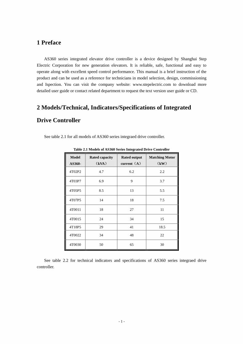
See table 2.1 for all models of AS360 series integraed drive controller.
Table 2.1 Models of AS360 Series Integrated Drive Controller
Model
AS360-
Rated capacity
(kVA)
Rated output
current(A)
Matching Motor
(kW)
4T02P2 4.7 6.2 2.2
4T03P7 6.9 9 3.7
4T05P5 8.5 13 5.5
4T07P5 14 18 7.5
4T0011 18 27 11
4T0015 24 34 15
4T18P5 29 41 18.5
4T0022 34 48 22
4T0030 50 65 30
See table 2.2 for technical indicators and specifications of AS360 series integraed drive
controller.
Page 2
- 2 -
Table 2.2 Technical Indicators/Specifications of AS360 Series Integrated Drive Controller
4T02P2 4T03P7 4T05P5 4T07P5 4T0011 4T0015 4T0018 4T0022 4T0030
Max matching motor
capacity(kW) 2.2 3.7 5.5 7.5 11 15 18.5 22 30
Rat
ed o
utp
ut
Rated capacity
(kVA) 4.7 6.9 8.5 14 18 24 29 34 50
Rated current
(A) 9 9 13 18 27 34 41 48 65
Max output
voltage (V) 400V:three-phase 380/400/415/440/460V(matching input voltage)
Inpu
t po
wer
Number of phases,
voltage, frequency 400V:three-phase 380/400/415/440/460V、50/60Hz
Voltage range
allowed -15%~+10%
Frequency range
allowed -5%~+5%
Endurance
capacity of
instantaneous
voltage drop
400V:keep running at AC300V or above;Activate under-voltage protection after
15ms from the moment when it drops from rated input condition to somewhere
lower than AC300V.
Bas
ic
char
acte
rist
ics Max accessible
floor 9 floor
Elevator running
speed ≤1.75m/s
Dri
ve
char
acte
rist
ics
Control mode PG card vector control
Startup torque 150% 0Hz(PG card vector control)
Speed control
scope 1:1000(PG card vector control)
Speed control
precision ±0.02%(PG card vector control 25±10℃)
Torque limit yes(set with parameter)
Torque precision ±5%
Frequency control
scope 0~120Hz
Frequency
precision
(temperature
fluctuation)
±0.1%
Frequency setting
resolution ±0.06Hz/120Hz
Output frequency
resolution
(calculation of
0.01Hz
Page 3
- 3 -
4T02P2 4T03P7 4T05P5 4T07P5 4T0011 4T0015 4T0018 4T0022 4T0030
resolution)
No-load startup
compensation
When the elevator load is unknown, suitable torque will, as per the ready-to-travel
direction of elevator, be applied on motor so as to ensure smooth start of elevator,
minimize the slipping and improve comfort at starting moment
Overload capacity Zero speed 150% , < 3Hz is 160%, > 3Hz is 200%
Brake torque 150% ( external braking resistor),integrated braking unit
Acceleration
Deceleration
time
0.01~600s
Carrier frequency 2~11kHz
Battery operation In case of blackout, the battery instantaneously supplies power to elevator for
leveling at low speed.
PG
Car
d i
nte
rfac
e p
ort
PG card output 5V、12V,300mA
PG card type Open collector output, push-pull output, SIN/COS、Endat absolute value type
PG card signal
frequency
dividing output
OA,OB orthogonal,frequency dividing coefficient 1~128
Co
ntr
ol
inpu
t/o
utp
ut
sign
al
Opt-coupler input
Control power
supply
Isolated 24V DC
Relay output
control power
supply
Isolated 24V DC
Low-voltage
opt-coupler
isolated input
24 channel。Switching capacity.Opt-coupler control signal is isolated 24V DC
input signal.
High-voltage
opt-coupler
isolated input
3 channel, Switching capacity。
Relay output 1 18 channel, Normal open contact, single-pole and single-throw, contact
capacity:resistive load,3A 250VAC or 3A 30VDC
Relay output 2 3 channel. Normal open contact, single-pole and single-throw, contact capacity:
resistive load,6A 250VAC
Button
Input/output
terminals
20 channels, could be extended to channels
Pro
tect
ion
op
tio
n
Motor overload
protection Able to use parameter setting for the protection curve of motor
Overload of
frequency
converter
< 3Hz is 160%,5 seconds, > 3Hz is 185%,10 seconds
Short-circuit Provide protection to elevator integrated drive controller when overcurrent occurs
Page 4
- 4 -
4T02P2 4T03P7 4T05P5 4T07P5 4T0011 4T0015 4T0018 4T0022 4T0030
protection to any tow phases at output side.
Input open phase
protection
In case that open phase inputted during operation, cut off output to protect the drive
controller
Output open phase
protection
In case that open phase outputted during operation, cut off output to protect the
drive controller.
Overvoltage
threshold Bus-bar voltage, 810V(400V series)
Under-voltage
threshold Bus-bar voltage 380V(400V series)
Instantaneous
blackout
compensation
15ms above protection
Heat sink overheat Protection through the thermistor
Antistall Antisall protection launched when running speed deviation more than 30% of the
rated speed
Impulse encoder
failure PG disconnection
Brake protection Protection launched when automatically detecting the abnormal condition of brake
Module protection Protection against over-current , short-circuit, overheating
Current sensor
protection Self-inspection when power connection
Speed reversal
protection Inspection through encoder
I²t protection Inspection through three-phase current
Protection against
input overvoltage 400V level> 725V,200V level >360V,stop and inspect
Output grounding
protection
Any phase grounding short-circuited during operation, cut off output and protect
the frequency converter.
Protection against
output imbalance
Cut off output and protect frequency converter, after three phase current output
imbalance being detected during running.
Short-circuit
protection for
brake resistor
Inspection when braking
Encoder
interference Evaluate the degree of interference of encoder and alarm
Over-speed
protection Protection launched when exceeding rated speed by 100%
Low-speed
protection
Protection launched when the elevator running speed is far lower than the rated
speed due to some reasons including failures.
Running time
governor
protection
Protection launched when floor passing time exceed the required time
Page 5
- 5 -
4T02P2 4T03P7 4T05P5 4T07P5 4T0011 4T0015 4T0018 4T0022 4T0030
Leveling switch
fault protection Protection launched when leveling switch is at fault
EEPROM fault Self-inspection when power connection
Dis
pla
y
LCD in Chinese
and English Menus at each level
En
vir
on
men
t
Surrounding
temperature -10~+45℃
Humidity Below 95%RH(no condensation)
Storage
temperature -20~+60℃(temperature allowable during short-term transport)
Application place indoor(no corrosive gas 、dust and the like)
Altitude Below 1000m
Str
uct
ure
Protection grade IP20
Cooling mode Force air-cooling
Installation mode In-cabinet installation
Page 6
- 6 -
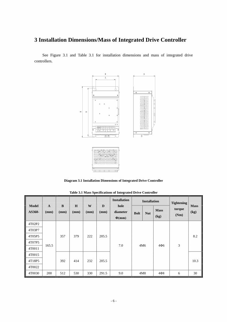
3 Installation Dimensions/Mass of Integrated Drive Controller
See Figure 3.1 and Table 3.1 for installation dimensions and mass of integrated drive
controllers.
W
A
BH
D
Diagram 3.1 Installation Dimensions of Integrated Drive Controller
Table 3.1 Mass Specifications of Integrated Drive Controller
Model
AS360-
A
(mm)
B
(mm)
H
(mm)
W
(mm)
D
(mm)
Installation
hole
diameter
Φ(mm)
Installation Tightening
torque
(Nm)
Mass
(kg) Bolt Nut Mass
(kg)
4T02P2
165.5
357 379 222 205.5
7.0 4M6 4Φ6 3
8.2
4T03P7
4T05P5
4T07P5
4T0011
4T0015
392 414 232 205.5 10.3 4T18P5
4T0022
4T0030 200 512 530 330 291.5 9.0 4M8 4Φ8 6 30
Page 7
- 7 -
4 Connecting Terminals of Integrated Drive Controller
4.1 Description of major loop terminals
See Diagram 4.1 for the major loop connecting terminals of AS360 series integrated drive
controller.
○+1 ○+2 B ○- R/L1 S/L2 T/L3 U/T1 V/T2 W/T3
Diagram 4.1 Main loop connecting terminals
See table 4.1 for main loop terminals function description of AS360 series integrated drive
controller.
Table 4.1. Function Description of Main Loop Terminals
Terminal Label Function Description
○+1
Connect DC reactor externally, short connected in factory
○+2
○+2
External braking resistor connection
B
○- DC bus negative output terminal
R/L1
Major loop AC power input; connect three-phase input power. S/L2
T/L3
U/T1
integrated drive controller output; connect three-phase
synchronous/asynchronous motor. V/T2
W/T3
Page 8
- 8 -
4.2 Description of Control Loop Terminals
See Diagram 4.2 for control loop terminal of AS360 series integrated drive controller.
Diagram 4.2 Control Loop Terminals
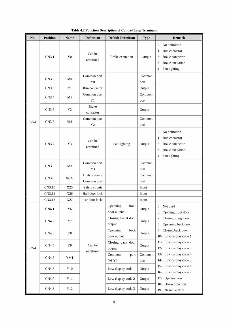
See Table 4.2 for control loop terminals function description of AS360 series integrated drive
controller.
Isolated power input
high-capacity relay output (front 8 pins)
small capacity relay output
RS232 hand operator interface
Button I/O
LV OC input
Expansion board
interface
HV OC input(last 4 pins)
High or low electrical level can be chosen by jumper J1. Left for the high level, right for the
low level
Page 9
- 9 -
Table 4.2 Function Description of Control Loop Terminals
No. Position Name Definition Default Definition Type Remark
CN3
CN3.1 Y0 Can be
redefined Brake excitation Output
0:No definition
1:Run contactor
2:Brake contactor
3:Brake excitation
4:Fan lighting
CN3.2 M0 Common port
Y0
Common
port
CN3.3 Y1 Run contactor
Output
CN3.4 M1 Common port
Y1
Common
port
CN3.5 Y2 Brake
contactor Output
CN3.6 M2 Common port
Y2
Common
port
CN3.7 Y3 Can be
redefined Fan lighting Output
0:No definition
1:Run contactor
2:Brake contactor
3:Brake excitation
4:Fan lighting
CN3.8 M3 Common port
Y3
Common
port
CN3.9 XCM High pressure
Common port
Common
port
CN3.10 X25 Safety circuit
Input
CN3.11 X26 Hall door lock
Input
CN3.12 X27 car door lock
Input
CN4
CN4.1 Y6
Can be
redefined
Openning front
door output Output
0:Not used
6:Opening front door
7:Closing frongt door
8:Openning back door
9:Closing back door
10:Low display code 1
11:Low display code 2
12:Low display code 3
13:Low display code 4
14:Low display code 5
15:Low display code 6
16:Low display code 7
17:Up direction
18:Down direction
19:Negative floor
CN4.2 Y7 Closing frongt door
output Output
CN4.3 Y8 Openning back
door output Output
CN4.4 Y9 Closing back door
output Output
CN4.5 YM1 Common port
Y6-Y9
Common
port
CN4.6 Y10 Low display code 1 Output
CN4.7 Y11 Low display code 2 Output
CN4.8 Y12 Low display code 3 Output
Page 10
- 10 -
No. Position Name Definition Default Definition Type Remark
CN4.9 Y13 Low display code 4 Output 20:Fire fighting back
21:buzzer
22:overload
23:arriving station bell
24:Full load
25:maintenance
26:Fan lighting 2
27:Open door ahead of time
28:High floor
29:integrated drive
Controller running
normally
30:Emergency leveling
25:maintenance
26:Fan lighting 2
27:Open door ahead of time
28:High floor
29:integrated drive
Controller running
normally
30:Emergency leveling
CN4.10 Y14 Low display code 5 Output
CN5
CN5.1 Y15 Low display code 6 Output
CN5.2 Y16 maintenance Output
CN5.3 YM2 Common port
Y10-Y16
Common
port
CN5.4 Y17 Up direction Output
CN5.5 Y18 Down direction Output
CN5.6 Y19 Negative floor Output
CN5.7 Y20 Fire fighting back Output
CN5.8 Y21 buzzer Output
CN5.9 Y22 overload Output
CN5.10 YM3 Common port
Y17-Y22
Common
port
CN8
CN8.1 24V 24V
CN8.2 COM COM
Common
port
CN8.3 L1
Can be
redefined
front door open
button Button
201:front door open button
202:front door close button
203:front door keep opening
204:Door 2 options
211~220 : 1~10 floor front
door instruction
221~229:1~9 floor front door
up call
232~240 : 2~10 floor front
door down call
301:Back door open button
302:Back door close button
303:Back door keep opening
311~320 : 1~10 floor back
door instruction
321~329:1~9 floor back door
up call
332~340 : 2~10 floor back
CN8.4 L2 front door close
button Button
CN8.5 L3 front door keep
opening Button
CN8.6 L4 back door open
button Button
CN8.7 L5
front door
1st floor
instruction
Button
CN8.8 L6
front door
2nd floor
instruction
Button
CN8.9 L7
front door
3rd floor
instruction
Button
CN8.10 L8 front door Button
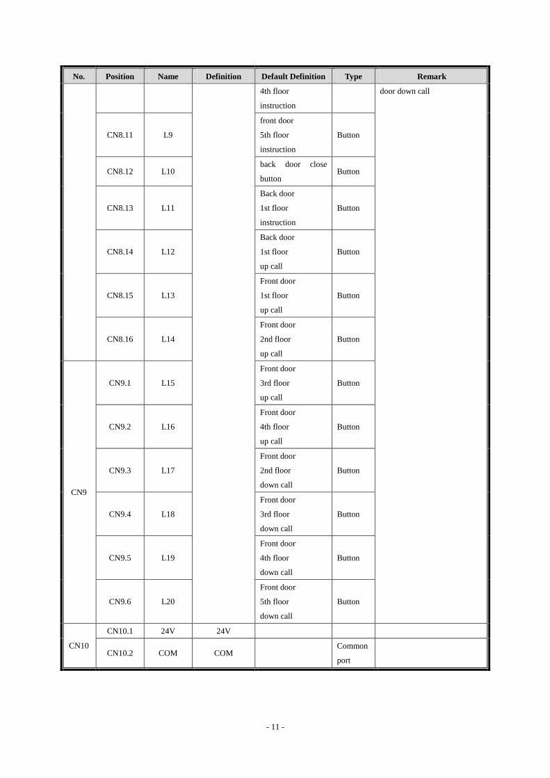
Page 11
- 11 -
No. Position Name Definition Default Definition Type Remark
4th floor
instruction
door down call
CN8.11 L9
front door
5th floor
instruction
Button
CN8.12 L10 back door close
button Button
CN8.13 L11
Back door
1st floor
instruction
Button
CN8.14 L12
Back door
1st floor
up call
Button
CN8.15 L13
Front door
1st floor
up call
Button
CN8.16 L14
Front door
2nd floor
up call
Button
CN9
CN9.1 L15
Front door
3rd floor
up call
Button
CN9.2 L16
Front door
4th floor
up call
Button
CN9.3 L17
Front door
2nd floor
down call
Button
CN9.4 L18
Front door
3rd floor
down call
Button
CN9.5 L19
Front door
4th floor
down call
Button
CN9.6 L20
Front door
5th floor
down call
Button
CN10
CN10.1 24V 24V
CN10.2 COM COM
Common
port
Page 12
- 12 -
No. Position Name Definition Default Definition Type Remark
CN10.3 X1 Can be
redefined Door area Input
Door area switch must be
defined as X1,X23 or X24
when there're 1 leveling
switch(F76=1); Up and down
leveling switch must be
defined as X1,X23 or X24
when there're 2 leveing
switches(F76=0)
CN10.4 X2
KMY detection
(Normal
close)
Input 1~99:Normal open
101~199:Normal close
4:KMY detection
5:KMB detection
6:brake switch 1
7:sealing star feedback
8:Open door ahead of time
detection
9:maintenance(only normal
close)
10:upgoing(Only normal
open)
11:downgoing: (Only normal
open)
12:Fire fighting back
13:reserved
14:Lock elevator
15:upper limit
16:lower limit
17:Up decelerate
18:Down decelerate
19:overload
20:full load
21:reserved
22:open front door in place
23:open back door in place
24:close front door in place
25:close back door in place
26:front door screen
27:back door screen
28:driver
29:drive straightly
30:driver reversing
31:independent
CN10.5 X3
KMB detection
(Normal
close)
Input
CN10.6 X4
detection
(Normal
close)
Input
CN10.7 X5 upgoing
Input
CN10.8 X6 downgoing
Input
CN10.9 X7 Can be
redefined
Fire fighting back Input
CN10.10 X8 Lock elevator Input
CN10.11 X9 Can be
redefined
upper limit(Normal
close) Input
CN10.12 X10 lower limit(Normal
close) Input
CN10.13 X11
Up decelerate
(Normal
close)
Input
CN10.14 X12
Down
decelerate
(Normal
close)
Input
CN10.15 X13
Can be
redefined
overload Input
CN10.16 X14
open front door in
place ( Normal
close)
Input
CN11
CN11.1 X15 front door screen
(Normal close) Input
CN11.2 X16 driver
Input
CN11.3 X17 driver reversing Input
CN11.4 X18 close front door in Input
Page 13
- 13 -
No. Position Name Definition Default Definition Type Remark
place ( Normal
close)
32:door 2 Selection
33:Emergency leavling
34:open door button
35:close door button
36:Safety circuit
37:Door lock circuit 1
38:Door lock circuit 2
39:half load
40:brake switch 2
41:front door safety contact
board
42:back door safety contact
board
43:back-up source
44:earthquake
45:firemen
46:terminal switch
CN11.5 X19 Full load Input
CN11.6 X20
open back door in
place ( Normal
close)
Input
CN11.7 X21
close back door in
place ( Normal
close)
Input
CN11.8 X22 back door screen
(Normal close) Input
CN11.9 X23 up leveling Input
Door area switch must be
defined as X1,X23 or X24
when there're 1 leveling
switch(F76=1); Up and down
leveling switch must be
defined as X1,X23 or X24
when there're 2 leveing
switches(F76=0)
CN11.10 X24 down leveling Input
J11 expansion interface
J12 Other encoder interface
Note:The Port definitions of CN4.6、CN4.7、CN4.8、CN4.9、CN4.10、CN5.1(That is outputs:Y10、Y11、
Y12、Y13、Y14、Y15、Y16)can be refered of the detailed instructions of F78 in "chapter 6.2 Detailed
instructions of mainboard F parameters"
Table4.3 Dial switch SW1 Setup instructions
SW1 ON Burning program state Factory setup is OFF
(Maintain OFF during operation)
Page 14
- 14 -
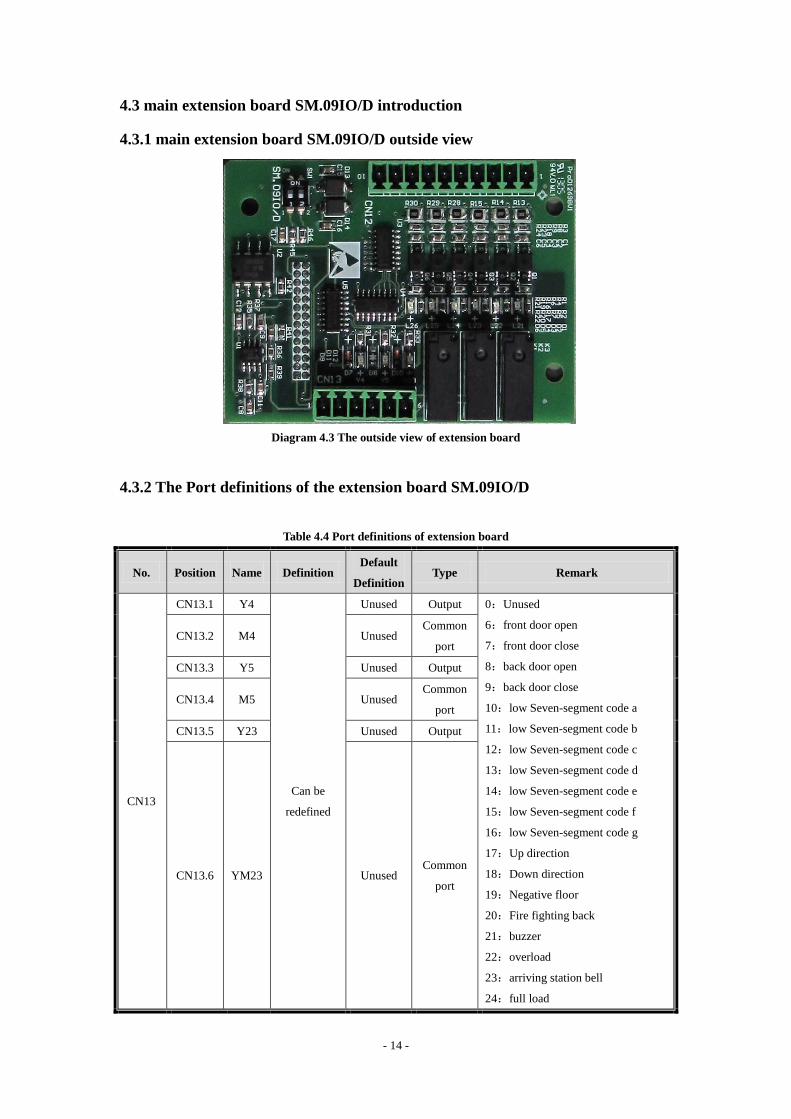
4.3 main extension board SM.09IO/D introduction
4.3.1 main extension board SM.09IO/D outside view
Diagram 4.3 The outside view of extension board
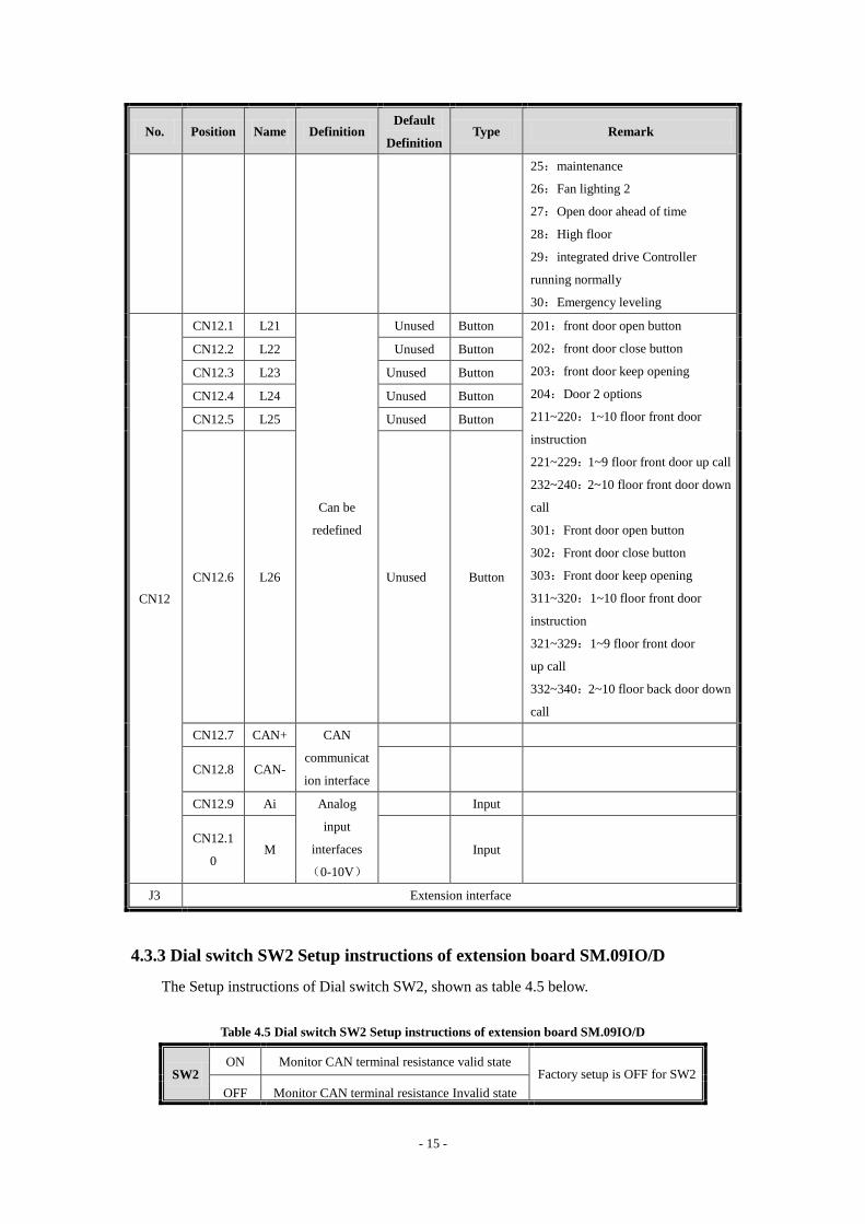
4.3.2 The Port definitions of the extension board SM.09IO/D
Table 4.4 Port definitions of extension board
No. Position Name Definition Default
Definition Type Remark
CN13
CN13.1 Y4
Can be
redefined
Unused Output 0:Unused
6:front door open
7:front door close
8:back door open
9:back door close
10:low Seven-segment code a
11:low Seven-segment code b
12:low Seven-segment code c
13:low Seven-segment code d
14:low Seven-segment code e
15:low Seven-segment code f
16:low Seven-segment code g
17:Up direction
18:Down direction
19:Negative floor
20:Fire fighting back
21:buzzer
22:overload
23:arriving station bell
24:full load
CN13.2 M4 Unused Common
port
CN13.3 Y5 Unused Output
CN13.4 M5 Unused Common
port
CN13.5 Y23 Unused Output
CN13.6 YM23 Unused Common
port
Page 15
- 15 -
No. Position Name Definition Default
Definition Type Remark
25:maintenance
26:Fan lighting 2
27:Open door ahead of time
28:High floor
29:integrated drive Controller
running normally
30:Emergency leveling
CN12
CN12.1 L21
Can be
redefined
Unused Button 201:front door open button
202:front door close button
203:front door keep opening
204:Door 2 options
211~220:1~10 floor front door
instruction
221~229:1~9 floor front door up call
232~240:2~10 floor front door down
call
301:Front door open button
302:Front door close button
303:Front door keep opening
311~320:1~10 floor front door
instruction
321~329:1~9 floor front door
up call
332~340:2~10 floor back door down
call
CN12.2 L22 Unused Button
CN12.3 L23 Unused Button
CN12.4 L24 Unused Button
CN12.5 L25 Unused Button
CN12.6 L26 Unused Button
CN12.7 CAN+ CAN
communicat
ion interface
CN12.8 CAN-
CN12.9 Ai Analog
input
interfaces
(0-10V)
Input
CN12.1
0 M Input
J3 Extension interface
4.3.3 Dial switch SW2 Setup instructions of extension board SM.09IO/D
The Setup instructions of Dial switch SW2, shown as table 4.5 below.
Table 4.5 Dial switch SW2 Setup instructions of extension board SM.09IO/D
SW2 ON Monitor CAN terminal resistance valid state
Factory setup is OFF for SW2
OFF Monitor CAN terminal resistance Invalid state
Page 16
- 16 -
4.4 PG Card
The following part introduce the PG card suitable for the SIN/COS encoder.
4.4.1 SIN/COS PG card terminal arrangements
See diagram 4.4 for SIN/COS PG card (Model AS.T024) terminal arrangements.
Diagram 4.4 SIN/COS PG card (Model AS.T024) terminal arrangements
4.4.2 SIN/COS PG Card Terminal Label
JP2 is input terminal (14-pin socket) with labels as follows:
1 2 3 4 5 6 7 8 9 10 11 12 13 14
NC NC R- R+ B- B+ A- A+ D- D+ C- C+ 0V V+
JP3 is (fractional frequency) output terminal with labels as follows:
FA V0 FB V0
4.4.3 SIN/COS PG card terminal function description
See Table 4.4 for SIN/COS PG card (AS.T024) terminal functions.
Page 17
- 17 -
Table 4.6 SIN/COS PG card terminal function description
Name Terminal Label Function Description Specifications
Collector open
output
FA fractional frequency signal output Phase A Triode close/open output
(Max. output frequency
100kHz);
0V 24V GND
FB Fractional frequency signal output Phase B
0V 24V GND
Encoder input
A+,A- Encoder Phase A signal
Differential signal; Max.
input frequency: 100kHz
B+,B- Encoder B phase signal
R+,R- Encoder Z signal
C+,C- Encoder SIN signal
D+,D- Encoder COS signal
V+ +5V
0V +5V GND
Page 18
- 18 -
5 Parameter Table of Integrated Drive Controller
Table 5.1 F Parameter List
No. Name Factory
Setup Scope Unit Remarks
F00 Accelerating slope 0.3 0.200~1.500 m/s2
F01 Decelerating slope 0.3 0.200~1.500 m/s2
F02 S curve T0 (initial S angle time
T0) 1.3 0.300~3.000 s
F03 S curve T1 (S angle T1 at end of
acceleration) 1.1 0.300~3.000 s
F04 S curve T2 (S angle time T2 at
the beginning of deceleration) 1.1 0.300~3.000 s
F05 S curve T3 (S angle time T3 at
the end of deceleration) 1.3 0.300~3.000 s
F06 Nominal speed 0.5 0.100~
10.000 m/s
F09 Parking floor 1 1~10 ×
F10 Offset floor 0 0~10 ×
F11 Floor number 5 2~10 ×
F12 Inspection speed 0.25 0~0.630 m/s
F13 Re-leveling speed 0.06 0.010~0.150 m/s
F14 Closing delay 1 (repsonse to hall
call) 20 0~300.0 s
F15 Closing delay 2 (repsonse to car
call) 20 0~300.0 s
F16 brake delay 0.2 0~2.0 s
F17 Automatic enable signal release
time 0.6 0.2~3.0 s
F18 Fire floor 1 1~10 ×
F20 Base station return delay time 0 0~65535 s 0 represents not open; other numbers
represents open and delayed time.
F21 Leveling switch motion delay
distance (full-speed) 6 0~40 mm
F22 Single and Duplex return to base
station 1 1~10 ×
F23 Group control mode 0 0~3 ×
F25
Input type 1 (normal open or
close setup for X0~X15 input
point)
28430 0~65535 ×
Page 19
- 19 -
No. Name Factory
Setup Scope Unit Remarks
F26
Input type 2 (normal open or
close setup for X16~X25 input
point)
58 0~65535 ×
F29 Service floor 1 (Set up if 1~16
floors can be docked) 65535 0~65535 ×
F33 Auomatic operation interval for
test run 5 0~60 s
F34 Automatic operation times for
test run. 0 0~65535
F35
Firefighting switch input
definition and firefighting mode
selection
0 0~65535 ×
Bit0: 0: ordinary firefighting, 1: Schindler
fire mode
Bit1: 0: fireman switch without lift car
board; 1: fireman switch with lift car board
Bit2: 0: ordinary firefighting signal display;
1: Shandong firefighting signal display
Bit3: 0: Motherboard X15 input for
firefighting return; 1: Motherboard X15
input for fireman switch
F36 Band-type Brake switch detection
mode 0 0~2 ×
F40 Weight data bias 48 0~100 %
F41 Weighter study and parameter
setup command. 0
0/1/2/10
/20/30/
40/50/60
×
F43 Buzzing/flashing function
selection for attendant status call 3 0~65535 ×
F44 Serial communication address
(255 for non-monitor) 255 0~255 ×
F49 Emergency leveling orientation
mode 0 0~2
F50
Front door opening permission 1
(opening setup value for 1~16
floors)
65535 0~65535 ×
F53
Rear door opening permission 1
(opening setup value for 1~16
floors)
0 0~65535 ×
F56 Up leveling adjustment (50 to
refernece value) 50 0~240 mm
F57 Down leveling adjustment (50 to
refernece value) 50 0~240 mm
F59 Zero speed brake delay 0 0~10.00 0.01s
Page 20
- 20 -
No. Name Factory
Setup Scope Unit Remarks
F61 Arrival distance by arrival gong 1200 0~4000 mm
F62 Anti-slipping limit time 32 20~45 s
F65 Base electrode lock mode 0 0~1 × 0: No base lock,
1: output contactor off, immediate lock
F66 With or whithout upper and
lower limt 0 0~1
0:no
1:yes
F67 With or whithout entension board 0 0~1
0:no
1:yes
F68 open the function of learning
normal open, normal close 0 0~1
0:open
1:close
F70 Light load uplink gain 100 0-300 %
F71 Light load lowlink gain 100 0-300 %
F72 Heavy load uplink gain 100 0-300 %
F73 Heavy load lowlink gain 100 0-300 %
F74 Light load height gain 512 0-1024
F75 Heavy load height gain 512 0-1024
F76 The number of leveling switch 0 0~1
0:Two leveling switch
1:One leveling switch
F77 High floor output value 1 0~6
F78 Display code output type option 0 0~3
F79 With or without end station
switch 0 0~3
Bit0:with up end station
Bit1:with down end station
F81 Serial communication function
selection 0 0~1
F82
The time delay of finding door
area after single leveling switch
upward
10 1~100 0.1s
F83
The time delay of finding door
area after single leveling switch
downward
10 1~100 0.1s
F115 The limit time of opening door
time delay 15 3~30 s
F116 The limit time of closing door
time delay 15 3~30 s
F117
The delay time of door foced to
close or the time of keeping the
door open
120 0~1800 s
F118 Opening time for the disabled 10 0~1800 s
Page 21
- 21 -
No. Name Factory
Setup Scope Unit Remarks
F120 Car call number when
anti-nuisance function activates. 0 0~30 ×
F121 Activate forced closing function
(0 represents not activate) 0 0~1 ×
F122 Signal delay release time in
Inspection. 0.3 0~10.0 s
F128 Control of front and rear doors 1 0~15 ×
F129 Activate the functions of
re-leveling and/or pre-opening 0 0~3 ×
F130 Maintain the opening/closing
torque 0 0~7 ×
Bit0: 1: door maintaining open
Bit1: 1: door maintaining closed
Bit2: 1: door maintaining closed during
operation
F137 Service floor 1 (Floor 1~ 16)
when NS-SW function is set. 65535 0~65535 ×
F141 Time of delay release of the main
contactor (after enabled) 0.5 0.50~10.00 s
F145 Bus voltage gain 100 80~120 %
F146 Position error distance 180 180~1000 mm
F147 Protection of contact detection 0 0~1
F152 Lighting delay (fans turned off
automatically, delay lighting) 180 0~65535 S 0: do not turn off the lights
F153 high-voltage input detection with
or without hall door lock 1 0/1 ×
0: No
1: Yes
F156 With or without lock relay
contact detection 1 0/1 ×
0: No
1: Yes
F161 The function of floor blocking for
a time slot 0 0~65535 ×
Bit0: 1: block instruction
Bit1: 1: block upward call
Bit2: 1: block downward call
F163
Choose whether the back-up
power continues running after
returning to the base in case of
single elevator or parallel
connection
0 0/1 × 0: stop running
1: may continue running
F164 Type of weighing device 99 0~99 × See the manual for more detailed
explanation
Page 22
- 22 -
No. Name Factory
Setup Scope Unit Remarks
F165 Special control of door operation 0 0~65535 ×
Bit0: 1: door closed during Ispection
Bit1: 1: door closed during debug running
Bit2: 1: door opened at the base station for
the elevator
Bit3: 1: whether to open the door by LED
operator
F175 Creeping speed at startup 0.006 0~0.100 m/s
F180 Speed gain 100 0~110.0 %
F181 Elevator No. at mutual parallel
connection mode 0 0~1 ×
F182 Slow down switch series 0 0~10 × 0: determine automatically by speed
F183 Learn trip speed 0
0~Rated
speed of
elevator
m/s 0:self-learning speed is at the rate of 50%
of the rated speed
F186 Creeping time at startup 0.5 0~10.00 s
F187 Monitor items 0 0~255 ×
F196 Second base station at Duplex 0 0~10 ×
F200 inverter software version Factory
setup × Read-only
F201 Inverter drive mode 3 0 / 1 / 2 /3 ×
Set inverter basic mode:
0:V/F control mode
1:Vector control without speed sensor
2:Torque control with speed sensor
3:Vector control with speed sensor
F202 Motor type 0 0 / 1 × 0: Asynchronous
1: Synchronous
F203 Motor rated power
By
Inverter
parameter
0.40~
160.00 KW
F204 Motor nominal current
By
Inverter
parameter
0.0~300.0 A
F205 Motor nominal frequency 50 0.00~120.00 Hz
F206 Motor nominal rotation speed 1460 0~3000 rpm
F207 Motor nominal voltage
By
Inverter
parameter
0.~460 V
F208 Number of poles of motor 4 2~128 ×
F209 Motor nominal slip frequency 1.4 0~10.00 Hz
Page 23
- 23 -
No. Name Factory
Setup Scope Unit Remarks
F210 Encoder type 0 2000/1/2 ×
0:incremental Encoder
1:SIN/COS Encoder
2:Endat Encoder
F211 Encoder pulse number 1024 500~16000 PPr
F212 Zero speed PID adjustor
incremental P0 130 0.00~655.35 ×
F213 Zero speed PID adjustor integral
I0 80 0.00~655.35 ×
F214 Zero speed PID adjustor
differential D0 0.5 0.00~655.35 ×
F215 Low speed PID adjustor
incremental P1 70 0.00~655.35 ×
F216 Low speed PID adjustor integral
I1 30 0.00~655.35 ×
F217 Low speed PID adjustor
differential D1 0.5 0.00~655.35 ×
F218 Medium speed PID adjustor
incremental P2 120 0.00~655.35 ×
F219 Medium speed PID adjustor
integral I2 25 0.00~655.35 ×
F220 Medium speed PID adjustor
differential D2 0.2 0.00~655.35 ×
F221 High speed PID adjustor
incremental P3 140 0.00~655.35 ×
F222 High speed PID adjustor integral
I3 5 0.00~655.35 ×
F223 High speed PID adjustor
differential D3 0.1 0.00~655.35 ×
F224 Low speed point switch
frequency F0 1 0.0~100.0 %
F225 High speed point switch
frequency F0 50 0.0~100.0 %
F226 Zero servo time 0.5 0.0~30.0 s
F227 Band-type Brake release time 0.25 0.00~30.00 s
F228 Current slowdown time 0 0.00~10.00 s
F229 Torque compensation direction 0 0/1 × 0:positive direction
1:negative direction
F230 Torque compensation gain 100 0.0~200.0 %
F231 Torque compensation bias 0 0.0~100.0 %
Page 24
- 24 -
No. Name Factory
Setup Scope Unit Remarks
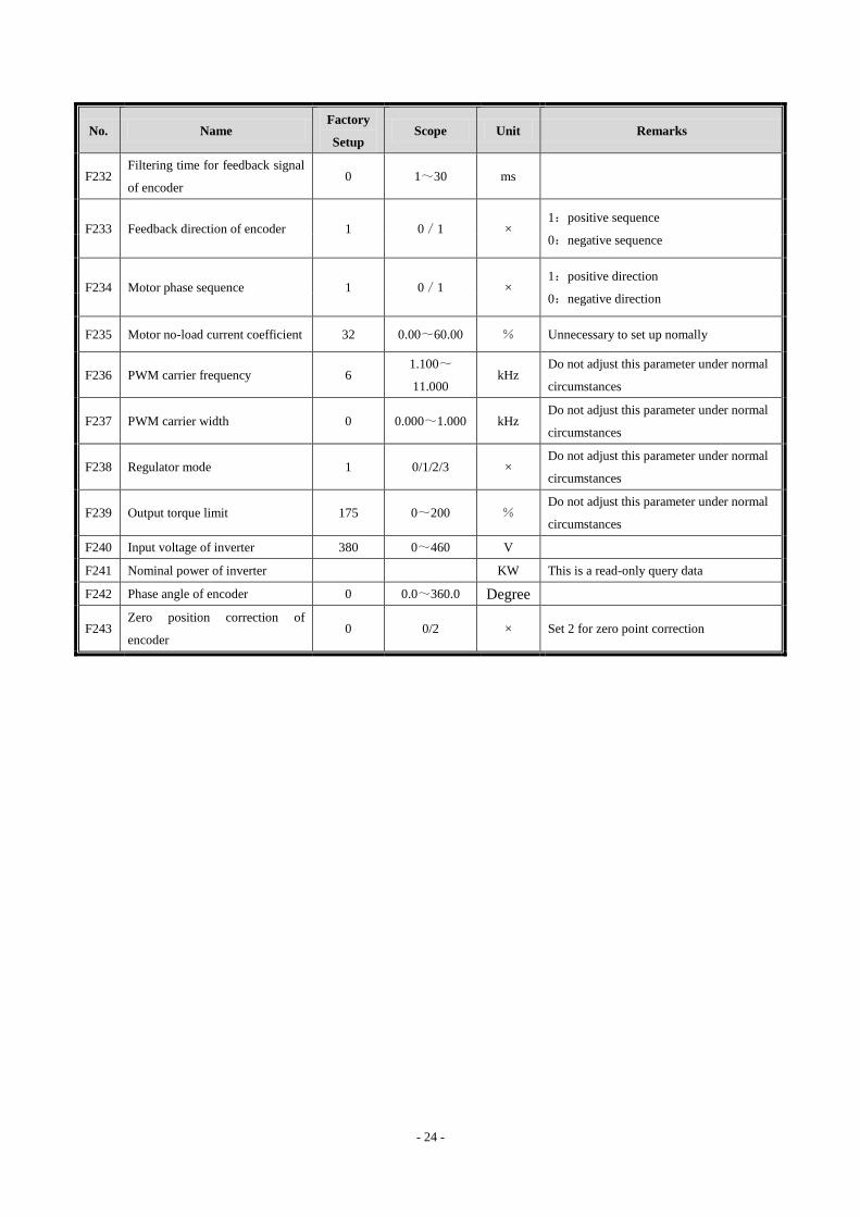
F232 Filtering time for feedback signal
of encoder 0 1~30 ms
F233 Feedback direction of encoder 1 0/1 × 1:positive sequence
0:negative sequence
F234 Motor phase sequence 1 0/1 × 1:positive direction
0:negative direction
F235 Motor no-load current coefficient 32 0.00~60.00 % Unnecessary to set up nomally
F236 PWM carrier frequency 6 1.100~
11.000 kHz
Do not adjust this parameter under normal
circumstances
F237 PWM carrier width 0 0.000~1.000 kHz Do not adjust this parameter under normal
circumstances
F238 Regulator mode 1 0/1/2/3 × Do not adjust this parameter under normal
circumstances
F239 Output torque limit 175 0~200 % Do not adjust this parameter under normal
circumstances
F240 Input voltage of inverter 380 0~460 V
F241 Nominal power of inverter
KW This is a read-only query data
F242 Phase angle of encoder 0 0.0~360.0 Degree
F243 Zero position correction of
encoder 0 0/2 × Set 2 for zero point correction
Page 25
- 25 -
6 Fault Analysis
6.1 Control System Self-Learning Fault Code
Table 6.1 Control System Self-Learning Fault Code Table
Code Description Sub
Code Fault Cause Analysis
10 Dislocation of upward
deceleration switch 1
01 Lost upward deceleration switch 1; Upward deceleration switch 1 have
not been learn.
02
Upward deceleration switch 1 is too short from the terminal station;
When the level of deceleration switch is higher than 1; The action
position of upward deceleration switch 1 is higher than 3/5 top floor
position height; Or, The action position of upward deceleration switch
1 is higher than the shortest deceleration distance.
09 Up terminal station switch haven't been learn.
11
Dislocation of
downward
deceleration switch 1
01
Lost downward deceleration switch 1; Downward deceleration switch
1 have not been learn when Downward deceleration switch 1 and
higher lever switches act.
02
Downward deceleration switch 1 is too short from the terminal station;
When the level of deceleration switch is higher than 1; The action
position of downward deceleration switch 1 is lower than 3/5 bottom
floor position height; Or, The action position of downward deceleration
switch 1 is lower than the shortest deceleration distance.
09 Down terminal station switch haven't been learn.
27 Up leveling switches
haven't been detected. 01
Row on the elevator, the flat during the switch OFF on flat layer switch
did not change.
When the elevator go upstairs, and down leveling switch is OFF, up
leveling switch did not change.
28
Down leveling
switches haven't been
detected.
01
Row on the elevator, the flat during the switch OFF on flat layer switch
did not change.
When the elevator go upstairs, and down leveling switch is OFF, up
leveling switch did not change.
68
The combination of
the length of the self
study leveling spile
and the distance
between the leveling
switches does not
meet the requirements
01
When the elevator go upwars, and the two leveling switches both have
not being detected, Class 1 downward deceleration switch turns from
ON to OFF, and the 2 leveling switches both have not change.
02
Leveling switch connected reversely, the state of uperword/downward
leveling switch turn from ON/ON to OFF/ON. When that happens,it is
judged to be leveling swith have being connected reversely.
03 The leveling spile is too long. Algthm: (length of the leveling spile +
leveling switch space)/2 greater than 900mm.
04 The leveling spile is too short. Algorithm: (length of the leveling spile
Page 26
- 26 -
Code Description Sub
Code Fault Cause Analysis
+ leveling switch space)/2 less than 100mm.
05 The leveling area is too long. Algorithm: (length of the leveling spile -
leveling switch space)/2 greater than 100mm.
06 The leveling area is too short. Algorithm: (length of the leveling spile -
leveling switch space)/2 less than 100mm.
69
The inconsistency of
the number of self
study spiles and the
total storey number of
the elevator and the
number of the floor
bias
01 It is inconsistency of the self learning floor and the floor set by
parameter
02 The height of storey is too long, and greater than 8m.
6.2 Other Control System Fault Code
Table 6.2 Other Control System Fault Code Table
Code Description Sub
Code Fault Cause Analysis
02
Door lock
disengagement during
operation
(emergency stop)
01 Safety loop during operation without door lock high pressure point
02 Safety loop during operation without door lock low pressure point
03 Elevator overtravels
when going upwards
01 In automatic operation, the upper and lower limit switches are in action
at the same time and the elevator is not at the highest level
03 In upward operation, the elevator crosses the top level
04 Elevator overtravels
when going downwards
01 In automatic operation, the upper and lower limit switches are in action
at the same time and the elevator is not at the lowest level
03 In downward operation, the elevator crosses the bottom level
05 Door lock will not open 01 Door fails to open in position after the door-open signal outputs for
consecutive 15 seconds, reports failure for 3 times
06 Door lock will not close
01
Door fails to close in position after the door-close signal outputs for
consecutive 15 seconds and reports failure for 8 times.
The close button flashing after fault protection
02
Inconsistence for 4 seconds between door-close limit and door lock
determines time-out for door close. Failure reported after 8
inconsistencies.
The close button flashing after fault protection.
The door lock anti-shake parameter is added into door keeping close
parameter(F130),whitch keeping output after the door closed for 0.5s.
Page 27
- 27 -
Code Description Sub
Code Fault Cause Analysis
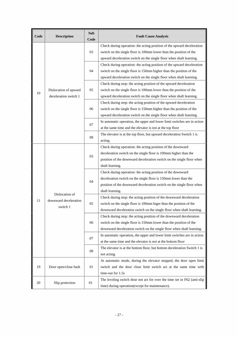
10 Dislocation of upward
deceleration switch 1
03
Check during operation: the acting position of the upward deceleration
switch on the single floor is 100mm lower than the position of the
upward deceleration switch on the single floor when shaft learning.
04
Check during operation: the acting position of the upward deceleration
switch on the single floor is 150mm higher than the position of the
upward deceleration switch on the single floor when shaft learning.
05
Check during stop: the acting position of the upward deceleration
switch on the single floor is 100mm lower than the position of the
upward deceleration switch on the single floor when shaft learning.
06
Check during stop: the acting position of the upward deceleration
switch on the single floor is 150mm higher than the position of the
upward deceleration switch on the single floor when shaft learning.
07 In automatic operation, the upper and lower limit switches are in action
at the same time and the elevator is not at the top floor
08 The elevator is at the top floor, but upward deceleration Switch 1 is
acting.
11
Dislocation of
downward deceleration
switch 1
03
Check during operation: the acting position of the downward
deceleration switch on the single floor is 100mm higher than the
position of the downward deceleration switch on the single floor when
shaft learning.
04
Check during operation: the acting position of the downward
deceleration switch on the single floor is 150mm lower than the
position of the downward deceleration switch on the single floor when
shaft learning.
05
Check during stop: the acting position of the downward deceleration
switch on the single floor is 100mm higer than the position of the
downward deceleration switch on the single floor when shaft learning.
06
Check during stop: the acting position of the downward deceleration
switch on the single floor is 150mm lower than the position of the
downward deceleration switch on the single floor when shaft learning.
07 In automatic operation, the upper and lower limit switches are in action
at the same time and the elevator is not at the bottom floor
08 The elevator is at the bottom floor, but bottom deceleration Switch 1 is
not acting.
19 Door open/close fault 01
At automatic mode, during the elevator stopped, the door open limit
switch and the door close limit switch act at the same time with
time-out for 1.5s
20 Slip protection 01 The leveling switch dose not act for over the time set in F62 (anti-slip
time) during operation(except for maintenance).
Page 28
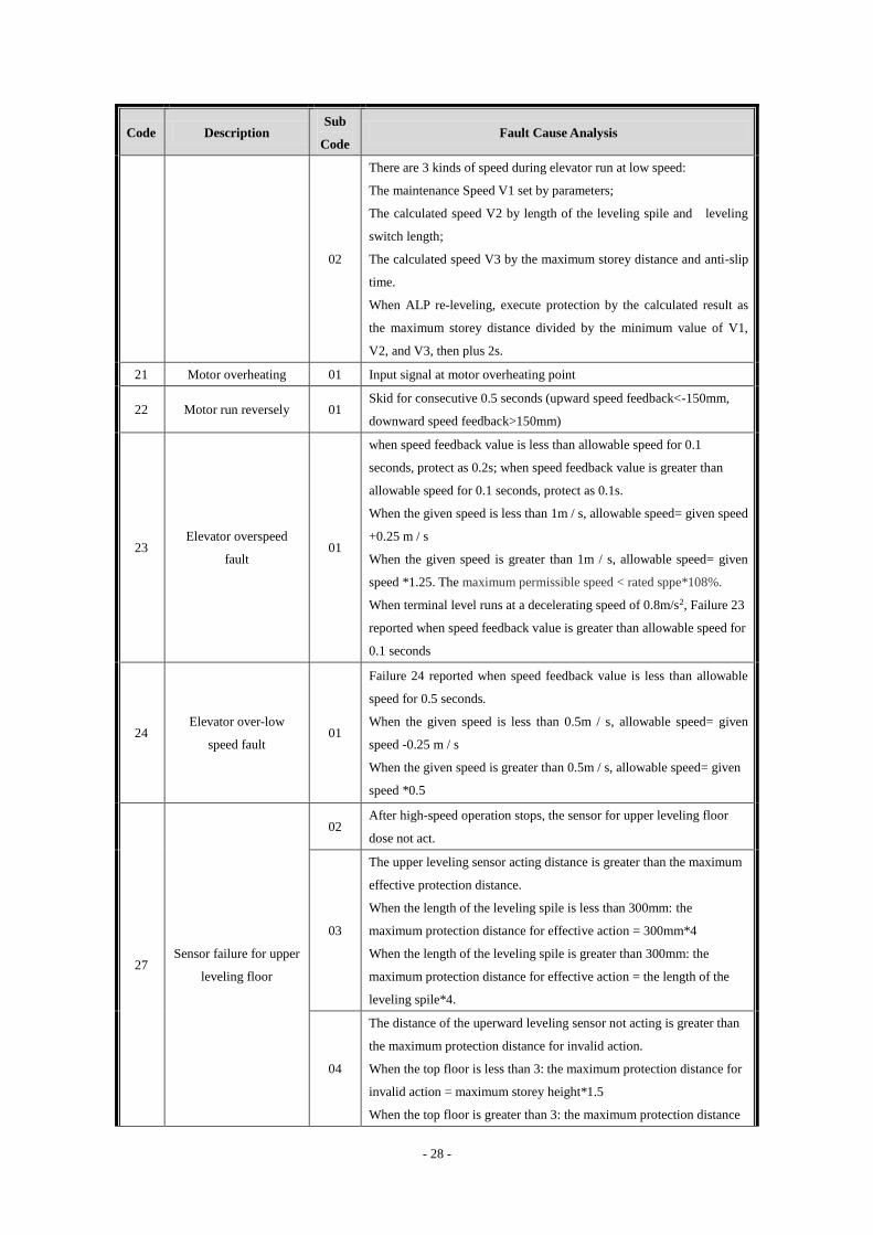
- 28 -
Code Description Sub
Code Fault Cause Analysis
02
There are 3 kinds of speed during elevator run at low speed:
The maintenance Speed V1 set by parameters;
The calculated speed V2 by length of the leveling spile and leveling
switch length;
The calculated speed V3 by the maximum storey distance and anti-slip
time.
When ALP re-leveling, execute protection by the calculated result as
the maximum storey distance divided by the minimum value of V1,
V2, and V3, then plus 2s.
21 Motor overheating 01 Input signal at motor overheating point
22 Motor run reversely 01 Skid for consecutive 0.5 seconds (upward speed feedback<-150mm,
downward speed feedback>150mm)
23 Elevator overspeed
fault 01
when speed feedback value is less than allowable speed for 0.1
seconds, protect as 0.2s; when speed feedback value is greater than
allowable speed for 0.1 seconds, protect as 0.1s.
When the given speed is less than 1m / s, allowable speed= given speed
+0.25 m / s
When the given speed is greater than 1m / s, allowable speed= given
speed *1.25. The maximum permissible speed < rated sppe*108%.
When terminal level runs at a decelerating speed of 0.8m/s2, Failure 23
reported when speed feedback value is greater than allowable speed for
0.1 seconds
24 Elevator over-low
speed fault 01
Failure 24 reported when speed feedback value is less than allowable
speed for 0.5 seconds.
When the given speed is less than 0.5m / s, allowable speed= given
speed -0.25 m / s
When the given speed is greater than 0.5m / s, allowable speed= given
speed *0.5
27 Sensor failure for upper
leveling floor
02 After high-speed operation stops, the sensor for upper leveling floor
dose not act.
03
The upper leveling sensor acting distance is greater than the maximum
effective protection distance.
When the length of the leveling spile is less than 300mm: the
maximum protection distance for effective action = 300mm*4
When the length of the leveling spile is greater than 300mm: the
maximum protection distance for effective action = the length of the
leveling spile*4.
04
The distance of the uperward leveling sensor not acting is greater than
the maximum protection distance for invalid action.
When the top floor is less than 3: the maximum protection distance for
invalid action = maximum storey height*1.5
When the top floor is greater than 3: the maximum protection distance
Page 29
- 29 -
Code Description Sub
Code Fault Cause Analysis
for invalid action = maximum storey height*2.5
05
After the elevator go uperward crosses over the top level, when
re-leveling , and downward leveling switch turns from OFF to ON, the
upward leveling switch dose not act.
28 Sensor failure for lower
leveling floor
02 The sensor for lower leveling floor dose not act, after the elevator
whitch run at a high speed stopped.
03
The downward leveling sensor acting distance is greater than the
maximum effective protection distance.
When the length of the leveling spile is less than 300mm, the
maximum protection distance for effective action = 300mm*4
When the length of the leveling spile is greater than 300mm: the
maximum protection distance for effective action = the length of the
leveling spile*4.
04
The distance of downward leveling sensor not acting is greater than the
maximum protection distance for invalid action.
When the top floor is less than 3: the maximum protection distance for
invalid action = maximum storey height*1.5
When the top floor is greater than 3: the maximum protection distance
for invalid action = maximum storey height*2.5
05
After the elevator go downward crosses over the bottom level, when
re-leveling , and upward leveling switch turns from OFF to ON, the
downward leveling switch dose not act.
30 Leveling position error
is too large 01
Detect the leveling position error when elevator stops. This failure
report when the error detected is greater than the value set by F146.
32
Safety loop
disconnected in
operation
01 Safety loop high pressure point disconnected in operation.
02 Safety loop low pressure point disconnected in operation.
35 Brake contactor contact
fault
01 The brake contactor adheres
02 The brake contactor does not suck
03 The detection Connection of the brake contactor is broken
04 The detection Connection of the brake contactor is short met
36 Output contactor
contact fault
01 Motherboard has no drive signal on circuit contactor, but input signal is
detected at input testing point (adhesion failure)
02 Motherboard has drive signal on circuit contactor, but input signal is
not detected at input testing point (non-adhesion failure)
37 Door-lock contactor
contact fault
01 Door lock contactor adhesion failure, without door lock high voltage
detection point, and with low voltage detection point.
02 Door-lock close signal input exists when the door-open limit signal is
in action
03 Hall door lock contactor adhesion failure, without door lock high
voltage detection point, and with low voltage detection point.
Page 30
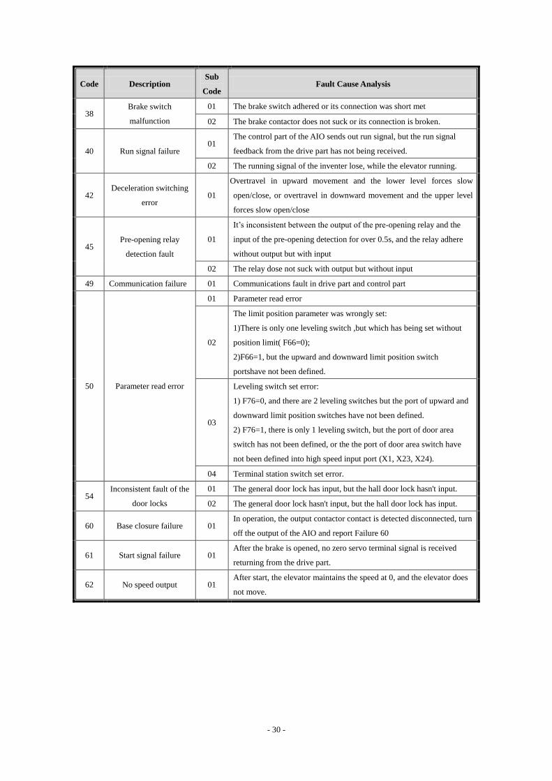
- 30 -
Code Description Sub
Code Fault Cause Analysis
38 Brake switch
malfunction
01 The brake switch adhered or its connection was short met
02 The brake contactor does not suck or its connection is broken.
40 Run signal failure 01
The control part of the AIO sends out run signal, but the run signal
feedback from the drive part has not being received.
02 The running signal of the inventer lose, while the elevator running.
42 Deceleration switching
error 01
Overtravel in upward movement and the lower level forces slow
open/close, or overtravel in downward movement and the upper level
forces slow open/close
45 Pre-opening relay
detection fault
01
It’s inconsistent between the output of the pre-opening relay and the
input of the pre-opening detection for over 0.5s, and the relay adhere
without output but with input
02 The relay dose not suck with output but without input
49 Communication failure 01 Communications fault in drive part and control part
50 Parameter read error
01 Parameter read error
02
The limit position parameter was wrongly set:
1)There is only one leveling switch ,but which has being set without
position limit( F66=0);
2)F66=1, but the upward and downward limit position switch
portshave not been defined.
03
Leveling switch set error:
1) F76=0, and there are 2 leveling switches but the port of upward and
downward limit position switches have not been defined.
2) F76=1, there is only 1 leveling switch, but the port of door area
switch has not been defined, or the the port of door area switch have
not been defined into high speed input port (X1, X23, X24).
04 Terminal station switch set error.
54 Inconsistent fault of the
door locks
01 The general door lock has input, but the hall door lock hasn't input.
02 The general door lock hasn't input, but the hall door lock has input.
60 Base closure failure 01 In operation, the output contactor contact is detected disconnected, turn
off the output of the AIO and report Failure 60
61 Start signal failure 01 After the brake is opened, no zero servo terminal signal is received
returning from the drive part.
62 No speed output 01 After start, the elevator maintains the speed at 0, and the elevator does
not move.
Page 31
- 31 -
7 User Guidance of Seven-Segment Code Display Manipulator
See the appearance and meaning of the Seven-Segment Code Display Manipulator as shown
in diagram 7.1, and detailed descriptions for the functions of the operation keys in Table 7.2.
Digital Tubes
Operation Keys
Diagram7.1 Meaning of Seven-Segment Code Display Manipulator
7.1 LED Indicator Light
Seven-Segment Code Display Manipulator has 4 LED Indicator Lights on its left. See
Table7.1 for the meanings of the 4 lights.
Table8.1 Meanings of D110~D113
Code Meaning
D110 When the safety loop conducts, this light turn bright; When the safety loop is broken, this light turn dark.
D111 State flashing light,when in normal state, flashes rapidly; when in self-study state, flashes at medium speed;
when in fault state, falshes slowly.
D112 Tuns bright when the general door lock high presure loop conducts; Turns dark when the general door lock
high presure loop disconnected.
D113 Tuns bright when the hall door lock high presure loop conducts; Turns dark when the hall door lock high
presure loop disconnected.
Page 32
- 32 -
7.2 Function Keys
There are 9 keys at the bottom of Manipulator. See Table 7.2 for their functions.
Table7.2 Key Function Description
Button Name of
Button Function
Upward
button
1. One item upward when browsing the menu;
2. Input one digit more.
Downwar
d button
1. One item downward when browsing the menu;
2. Input one digit less.
Leftward
button
1. One item leftward when selecting functions;
2. Cursor moves leftward when inputting data.
Rightward
button
1. One item rightward when selecting functions;
2. Cursor moves rightward when inputting data.
ESC
Esc button Cancel input
E NT E R
MENU
button
1. Modify parameters when browsing them
2. Save while entering data
7.3 Operation of Manipulator
7.3.1 Menu Structure
See Diagram 7.2 for the main menu structure. Due to the limitation of the seven-segment
code and button structure, the operational interface usually uses the first level menu structure.
Press the "left"and" right"key to switch between various menus.
Page 33
- 33 -
Diagram 7.2 Menu Structure
7.3.2 Switch between various menus by the left and right keys
On the first level main menu interface, press the left or right key to switch between various
menus. The elevator running state interface is displayed when power on each time. Detailed
descriptions of each menu are as follows:
1. Elevator running state (the menu displayed when power on)
State of Door
Floor Located
Running State
This menu displays the basic status of the elevator, including: the running state, the floor
located, the state of door.
In Running State:
Elevator going upward, Elevator going downward, Elevator at
stop
Back door
open allowed
Reset control
parameter
Reset failure
code
Reset drive
parameter
Driver
program
version
Controller
program
version
Elevator run
status
Front door
open allowed
Self study
instruction
Instruction
recorded
Permissive
stop floors
Input type
Elevator
speed
Code of fault
Year of
system
Date of
system
Time of
system
Level 1 Main menuSwitch among menus by “ < ” and ” > ” keys
Open/close
door control
Shaft
parameter
Input state of
top board of
lift car
Password
log in
Process
diagnosis
F parameter
settingFloor display
Page 34
- 34 -
In the state of door:
Door opening, Door opened in position,
Door closing, Door closed in position.
2. Speed of Elevator
This menu displays the current running speed of the elevator, unit: m/s. As shown in the
figure above, the current speed is 1.75m/s。
3. Failure Code
Failure Code
Failure Code Number
The AIO may staore 20 failure codes. The latest failure code is under No.00. Use up and
down keys to view these failure codes. Press “Enter” to view the date of failure, press “left” and
“right” to view the time and floor of the failure, and press “ESC” to exit.
4. Well Parameters
Page 35
- 35 -
This parameter shows the data of the shaft and the length of the leveling spiles, distance of
the leveling switch and the position of the deceleration switch.
Specific operation is as follows: use the "up" and "down" keys to view the parameters. Such
as P02, "P-02"appears on the screen as shown above, wait a second, the screen shows the P02
parameter is 03.000, as shown above, you will see "03.000". Afterwards, "P-02" and "03.000"
display alternately, each for about one second, which inditates 3 meters between Floor 1 and Floor
2. The meaning of each parameter is as follows.
Table 7.3 Meaning of Shaft Parameters
No. Meaning
P01-P64 Shaft data from 1st -64th floor
P65 Leveling plug-in board length
P66 Leveling switch center distance
P67 Upper deceleration switch distance on 1st floor
P68 Upper deceleration switch distance on 2nd floor
P69 Upper deceleration switch distance on 3rd floor
P70 Upper deceleration switch distance on 4th floor
P71 Lower deceleration switch distance on 1st floor
P72 Lower deceleration switch distance on 2nd floor
P73 Lower deceleration switch distance on 3rd floor
P74 Lower deceleration switch distance on 4th floor
5. Input Status of Lift Car Top Board
GX No.
GX Input Status
The figure above means: GX0 has no input. Press "up" and "down" keys to select GX serial
number from 0 to 15. After the GX matching numbers is selected, the highest level shows that the
input has no valid input (0 for invalid input, 1 for valid input).
Page 36
- 36 -
HX No.
HX Input Status
The figure above means: HX0 has no input. Press "up" and "down" keys to select HX serial
number from 0 to 15. After the HX matching numbers is selected, the highest level shows that the
input end has no valid input (0 for invalid input, 1 for valid input).
6. Process Diagnosis
Code of Status
This menu displays the current status of the elevator by a two-digit number. The meaning of
the status code is as follows
Table 7.4 Meaning of Status Code
No. Description
0 Safety loop disconnected
1 Elevator breakdown
2 Motor overheating
3 Overload
4 Safety edge motion
5 Door opening button motion (door opening button or external call button
motion on the same floor in the same direction)
6 Door lock short circuit/door opening limit motion
7 Elevator door opening
8 Elevator door closing
9 Door closing limit
10 Upward limit
11 Downward limit
12 Door locked, matching running conditions
13 KMY contact being in detection
14 BY contact being in detection
Page 37
- 37 -
15 In zero speed servo
16 Elevator in straight running
17 Elevator in operation
18 Elevator door lock disconnected
19 Shaft learning not completed
20 Detec inverter enabled
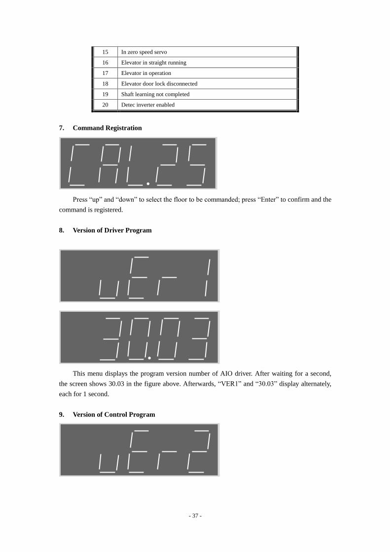
7. Command Registration
Press “up” and “down” to select the floor to be commanded; press “Enter” to confirm and the
command is registered.
8. Version of Driver Program
This menu displays the program version number of AIO driver. After waiting for a second,
the screen shows 30.03 in the figure above. Afterwards, “VER1” and “30.03” display alternately,
each for 1 second.
9. Version of Control Program
Page 38
- 38 -
This menu displays the program version number of AIO control. After waiting for a second,
the screen shows E02 in the figure above. Afterwards, “VER2” and “E02” display alternately,
each for 1 second.
7.3.3 LED Displayed Numbers and Letters
Because of the structure limit of LED, numbers and letters displayed are confusing
sometimes, therefore, the graph and meaning are given in the following table:
Table 7.5 Meaning of Status Code
Display Meaning Display Meaning Display Meaning Display Meaning
1
2
3
4
5
6
7
8
9
0
A
B
C
D
E
F
G
H
I
J
K
L
M
N
O
P
Q
R
S
T
U
V
W
X
Y
Z
Page 39
- 39 -
8 Elevator Commissioning Guide
8.1 Simple Commissioning Diagram
A new elevator equipped with AS360 AIO manufactured by Shanghai STEP Electric
Corporation. Its debugging process in electrical control and drive aspects is as follows.
Start
Check control cabinet before power on:
Check the grounding of power line, communication line and
encoder line
Commissioning of slow car:
Confirm that the safety loop and door lock loop are
connected
Confirm the upper/lower limit positions, upward/downward
forced slow, priority ispection for car top and circuit
connection
Set AIO parameters
Motor self study
Check upward or downward operation, and confirm that the
elevator runs in the correct direction
Check upward or downward operation, and confirm that the
manipulator displays the speed signal by “+” for upward and
“-” for downward
Adjustment of door open/close:
Confirm that the door open/close in position signals correctly
Page 40
- 40 -
Confirm that the safety contact edge and overload signal
correctly
Press door open/close button, and confirm it can open/close
normally
Shaft study:
Check upward operation. When the elevator passes through
leveling floor, confirm that the switch of the down leveling
switch acts before that of the up one.
Run the elevator to move upward to the up terminal landing
and downward to the down terminal landing. Confirm that
both upper forced slow limit position and lower forced slow
limit position act correctly
Ispection operation moves to the leveling landing of the
bottom and triggers the shaft study menu
In automatic state, the elevator will move automatically to the
top landing at shaft study speed.
Commissioning of express car:
Configure the AIO parameters correctly.
In automatic state, record instructions, and confirm that the
elevator can open/close door and brake normally
Record outside call signal, and confirm that the elevator can
normally and correctly stop the car, decelerate, cancel
registration and open the door.
Adjust the elevator comfort
Page 41
- 41 -
Test the elevator functions:
Automatic, attendant, independent, fire-fighting, lift lock,
parallel connection and group control test
Test the elevator safety:
Test the safety loop and door lock loop; adhesion protection
test of relay and contactor
Skid protection, staggered-floor protection, overload
protection, 110% load test
End of commissioning
Diagram 8.1 Simple Commissioning Diagram to the the controller and the frequency converters of the
AS360 AIO
8.2 Check before Power on
After installation of electrical control systems, electrical parts must be checked:
1. Check the connection of all parts, according to the user manual and electrical schematic
diagram.
2. Check whether the strong current part and the weak current part are connected. Check the
resistance between various voltage circuits and the earthing resistance with ohm grade of a
multimeter, and they should both be ∞.
3. Please carefully check whether the power incoming line of the control cabinet and motor
connections are correct, to avoid burning the elevator integrated drive controller after power on.
4. Check whether the control cabinet case, motor case, lift car earthing wire, hall door earthing
wire are reliably and securely grounding, to ensure personal safety.
▲ Note: The cabinet case and the motor case should be one point grounding.
8.3 Power on and Check
8.3.1 Confirm before Power on
1. Check the control cabinet for earthing short circuit before power on:
1) Input power line three-phase ground;
2) Motor line three-phase ground;
3) Terminal 220V ground;
4) Communication line ground;
5) Encoder line ground.
Please exclude all items above if short circuited.
Page 42
- 42 -
2. Grounding check: (Make sure the following items are reliably grounded)
1) Control cabinet ground;
2) Motor ground;
3) Lift car ground;
4) Door motor ground;
5) Trough ground;
6) Encoder shield control cabinet ground;
7) Encoder shield motor ground.
▲Note: single terminal grounded for asynchronous motor encoder shield, both terminals
grounded for synchronous motor Encoder shield.
3. Check encoder cable and power line wiring:
Encoder lines and power lines go separate trough.
8.3.2 Checks after Power on
1. Close the main power switch. If the green light on the phase sequence relay KAP is on, the
phase position is correct. If the green light is not on, shut off the main power supply, swap any
two-phase positions and then power on again.
2. Check all terminal voltage of the isolation transformer TCO in the control cabinet, and see
whether they are within the nominal range.
3. In the premise of carrying out the above steps correctly, proceed with the following steps:
1) Close the fuse FUn (n = 1, 2, 3 ...);
2) Close the door open/close power control switch; switching power supply TPB is powered
on, and the motherboard is electrified to run.
Each terminal voltage of switching power supply is as follows:
Table 8.1 Terminal voltage of switching power supply
Terminal L~N 24V~COM
voltage 220±7%VAC 24.0±0.3VDC
3) Reset the emergency stop switch of the control cabinet, connect safety loop, and the LED
lights corresponding to the motherboard turned on.
4) Check the following circuit:
a) Check whether the door lock loop is normal;
b) Check whether the leveling switch signal is normal;
c) The elevator status on the handheld programmer should show "Ispection";
If abnormal, please check and correct accordingly.
8.4 Configuration of System Basic Parameters and Self Study of Motor
Parameters
8.4.1 Configuration of System Basic Parameters
First set the system basic parameters in Table 5.1 correctly through a dedicated handheld
LCD Manipulator (see Chapter 5 for the use of hand-held Manipulator), and then make
commissioning as described in the following sections. For each new system, before setting
Page 43
- 43 -
parameters, it’s recommended to make a parameter reset through a dedicated LCD Manipulator.
Parameter reset as follows:
1) The elevator is in stop state;
2) Find "parameter reset" command interface in handheld Manipulator;
3) Align the cursor with "parameter reset" command and press Enter key, the system will
complete parameter reset immediately.
After parameter reset, all the parameters are changed into factory default values. Configure
the basic parameters on the basis of parameter reset, and the other parameters are set to be the
factory default values, to ensure normal and reliable operation of the system.
Table 8.2 System Basic Parameters
No. Name Default Value Scope Unit Remarks
F06 Elevator rated speed 0.500 0.100~
10.000 m/s
F09 Parking floor 1 1~64 ×
F10 Offset floor 0 0~64 ×
F11 Floor number 5 2~64 ×
F12 Ispection speed 0.250 0~0.630 m/s
F23 Group control mode 0 0~3 ×
F25
Input Type 1 (normal open or normal
closed configuration for X0 ~ X15
input point)
28430 0~65535 ×
F26
Input Type 2 (normal open or normal
closed configuration for X16 ~ X25
input point)
58 0~65535 ×
F202 Motor type 0 0 / 1 × 0: asychronous
1: synchronous
F203 Motor rated power
According to
inverter
parameter
0.40~
160.00 KW
F204 Motor rated current
According to
inverter
parameter
0.0~300.0 A
F205 Motor rated frequency 50.00 0.00~
120.00 Hz
F206 Motor rated rotary speed 1460 0~3000 rpm
F207 Motor rated voltage
According to
inverter
parameter
0.~460 V
F208 Motor pole number 4 2~128 ×
F209 Motor rated slip frequency 1.40 0~10.00 Hz
Page 44
- 44 -
No. Name Default Value Scope Unit Remarks
F210 Encoder type 0 0 / 1 / 2 ×
0:incremental Encoder
1:SIN/COS Encoder
2: Endat Encoder
F211 Encoder pulse number 1024 500~16000 PPr
Note:Before debugging, the basic parameters above must be correctly set; the basic
parameters of the motor can be input based on nameplate; according to the actual situation
of the site, please refer to Chapter 5 for the parameter setting method and detailed
definition.
8.4.2 Self learning of motor parameter
No motor parameters self study for the synchronous motor. And because AS360 series
elevator integrated drive controller adopts the most advanced and unique driver technology which
can automatically obtain Encoder phase angle data, therefore, there is no need for motor
auto-tuning of Encoder phase angle.
Note: The drive controller of AS360 series elevator AIO is used to control synchronous
motors, and every time after powered on, it will automatically capture Encoder information
at its first running, which takes 2 seconds or so. Therefore, the given running signal at this
time is slightly later than usual. Please do consider this detail in the design for this control
system, to avoid unnecessary failure.
For the asychronous motor, if the on-site motor parameters are confirmed to be very accurate,
in particular if the F209 (motor rated slip frequency) parameters are ensured to be accurate, the
following self study of motor internal characteristic parameters will not be necessary. However, if
the on-site motor parameters are not accurate enough, or with the purpose of ensuring excellent
operating characteristics of the system, self study can be carried out on site regarding the motor
internal operating parameters. Specific methods are as follows:
1) The connections between AS360 series elevator AIO and motor, between AIO and encoder
have been correctly completed;
2) Correctly power on for AIO;
3) Confirm that the safety loop and door lock loop are in a normal connected state;
4) The Auto/Ispection (or emergency power operation) switch is in position of Ispection (or
emergency power operation);
5) Select "asychronous motor self learning" command by Seven-Segment Code Display
Manipulator or LCD handheld Manipulator, and then press the Enter key;
6) AIO starts static self learning: the main contactor between AIO and the motor will
automatically suck, AIO obtains internal characteristics parameters of the motor by applying test
current on the motor. But the brake contactor will not suck, neither will the motor rotate;
7) The motor parameters complete their self learning after about 30 seconds, and the main
contactor releases automatically.
If the self learning does not work, mainly check the following items:
a) Whether the safety loop and the door lock loop are connected. If not, the main contactor
will not suck, so it is impossible to complete the self learning;
b) Whether the Encoder wiring is correct, whether A, B phase is reversed;
c) Whether the motor parameters are set correctly.
Page 45
- 45 -
8.5 Test Run of Slow Car
8.5.1 Ispection Operation of Engine Room and Preparations for Express Car
1. Points to be conformed by the engine room before slow car run
1) Ispection (or emergency power operation) switch of the control cabinet to "Ispection"(or
emergency power operation) position, and car top Ispection switch to "normal " position;
2) Safety loop and door lock loop work properly. Remember not to have lock shorted;
3) Encoder properly installed and wired correctly;
4) After powered on, the elevator integrated drive controller displays normally and checks
whether its parameters are set correctly, and handheld operator shows that the elevator is in a
status of "Ispection";
5) Connect correctly the tractor brake line onto the terminal in the control cabinet;
6) The upper and lower deceleration switches are correctly wired;
7) Ispection priority circuit on the car top is correctly wired;
2. Slow run of engine room
After the engine room slow car meets the operating conditions, press the upward (downward)
button on the control cabinet, and the elevator should go upward (downward) at a preset ispection
speed.
1) Observe whether the elevator follows the right direction, when it goes up or down. If in the
wrong direction, first check whether the up and down buttons are correctly wired. If correctly
wired, change the F234 motor phase sequence parameters (from 0 to 1or from 1 to 0).
2) When the slow car goes upward or downward, if the motor displayed by AIO feedbacks an
unstable speed or gives a value with significant higher, check the wiring between Encoder and the
motherboard: a) whether the cable is properly used. If the Encoder is a differential signal, use
shielded twisted-pair cable; if not differential signal, use general shielded cable; b) whether the
wiring is reasonable. The Encoder cable and power lines should not go trunking together, and
must be strictly separated; c) Check whether the shielding lines and net are reliably grounded.
3) If 2 leveling switches are installed, check whether the upper and lower leveling switches
are correctly wired: when the elevator goes up slowly and before passing through the leveling
floor,it should be confirmed that the down leveling switch act befor the up leveling switch.
Otherwise, the shaft cannot complete self study successfully. In case of that, must swap the
connection wiring of the two switches to the motherboard.
Note: Under many circumstances, slow running is not a ispection operation, but an
emergency power operation. At this point, in the safety loop, the safety gear switch, speed
limiter switch, upward speed protection switch, upper and lower terminal limit switch and
buffer reset switch are all shorted in the slow run time, to which particular attention should
be paid. It is recommended that the time and the distance of engine room emergency
running should not last too long, and do not run the lift to the teminal position.
8.5.2 Car Top Ispection Operation
After engine room slow run normally, you can run the car top Ispection operations. The
ispection speed may be adjusted appropriately lower in the first commissioning. After the operator
entering onto the car top:
1) First set immediately the car top Auto / Ispection switch to Ispection position, and confirm
that the upward and downward buttons in the control cabinet of the engine room do not work at
Page 46
- 46 -
this moment.
2) Jog the upward and downward buttons by car top, and confirm the button direction is the
same with the lift car running direction.
3) The operator should operate the elevator to the car top for a test run of back and forth,
carefully observe the surrounding of the lift car and confirm that there is no obstruction for the lift
car in the entire shaft.
4) By ispection operation to the car top, confirm that the shaft terminal deceleration switch
act correctly and its movement position correct.
5) By ispection operation to the car top, confirm that the shaft leveling switch and leveling
spiles are installed correctly, and at all leveling positions, each leveling switch act at the right
point.
8.5.3 Door Open/Close Adjustment
1) Set the elevator to ispection status and leave the lift car at the leveling position;
2) Electrify gantry crane power;
3) Move the car door manually, monitor on the handheld Manipulator and confirm whether
the door closing in place signal and the door opening in place signal work correctly;
4) Confirm the safety edge signal and the overload signal are not in action;
5) Confirm F165 parameter set to 0 (door operation allowed during the elevator ispection);
6) Have the car door in complete open state;
7) Press close button to confirm that the elevator door may close correctly until close in
place;
8) Then, press the button to open the door, make sure the elevator door may open correctly
until open in position.
8.6 Shaft Self Learning
Running well self study means the elevator runs at self study speed and records the position
of each floor and the position of each switch in the shaft. As the floor location is the basis for the
normal brake and operation of the elevator and for the floor display, before the express car running,
it is mandatory to run shaft self learning first.
8.6.1 Shaft Self Learning Method
1. Confirm the elevator complies with safe operating conditions.
2. Confirm that all switches and its wiring within the well are correctly installed, and the
connection of accompanying cables and outside cables are correct;
3. Make the elevator into ispection (or emergency electric operating) state;
4. Enter into self study menu by hand-held manipulator, follow the menu instructions, and find
well self study interface. Then move the cursor to well self study command and press Enter key;
5. Set the elevator into the automatic state, and the elevator runs down to the bottom landing at the
self learning speed (set by F183) and then automatically goes up at self study speed, and start well
self study. Well study is complete until the elevator arrives at the top leveling position and stops
automatically. The hand-held manipulator shows "self study completed" after the success of the
self study;
6. During the self study process, if the control system is abnormal, self study will stop and give the
corresponding fault code, and the hand-held Manipulator shows "self study unsuccessful".
Page 47
- 47 -
Main reasons for unsuccessful well self study include:
1) The total storey number set (F11) is inconsistent with the number of leveling spiles
installed in the well;
2) The number of slow down switches installed is inconsistent with the data set by parameter
F182;
3) The upper and lower leveling switch wiring reversed;
4) The installed positions of the leveling switch and leveling spiles are not accurate enough
that make leveling switch cann’t act effectively and correctly when the leveling spile of each floor
inserts;
5) The input point setting to leveling switch of normally open/normally closed is inconsistent
with the actual situation;
6) The terminal deceleration switch act wrongly or is installed to a wrong position (when the
lift car is at the ground floor leveling position, the down single landing terminal deceleration
switch must act; before the lift car goes upward to the leveling position of the next floor bottom,
the down single landing terminal deceleration switch must have been reset; when the lift car is at
the top floor leveling position, the up single landing terminal deceleration switch must act, before
the lift car goes downward to the leveling position of the next floor top, the up single landing
terminal deceleration switch must have been reset).
7) The input point setting to the terminal deceleration swith of normally open / normally
closed is inconsistent with the actual situation;
8) Encoder signal is interfered or Encoder has wiring error;
9) Leveling switch signal interfered;
10) Leveling switch failure or Encoder failure.
Special Note: during 2 landings / 2 stops self learnling,
1. As to the situation in which 2 leveling switches are installed, after the elevator in
inspection state, must run the elevator to the down limit position manually,and make sure
that the normally self learning operation can be done only after the up leveling switch
taking off.
2. As to the situation in which only 1 leveling switch is installed, the down limit and the down
limit position must short circuited, and make sure that the normally self learning operation
can be done only after the down leveling switch taking off.
Note: Express car operation is only possible after well self study.
8.7 Express Car Operation
1.Test Run of Express Car
After slow car running correctly, first of all, make sure the elevator meets safe operating
conditions. After well self learning, the elevator can proceed with express car test run. Specific
steps are as follows:
1) Set the elevator in normal state.
2) Monitor the selected floor interface by hand-held manipulator to select the floor to where
the elevator heading. Test run is possible for single floor, double floor, multi floors and full trip.
3) Check whether the elevator can correctly close the door, start, accelerate, run, cut,
decelerate, stop, cancel and open.
4) In case of abnormal operation, follow the fault code (see Chapter 6) and operate
Page 48
- 48 -
accordingly.
2.Safety Test
1) Safety loop
Testing requirements: when the elevator stops,and any of the safety switches acts, and after
safety loop is disconnected, the elevator can not start; when the elevator is under Ispection
operation, any of the safety switches motions, and after safety loop is disconnected, the elevator
takes an emergency stop.
2) Door lock loop
Testing requirements: when the elevator stops, after any of the hall door locks is disconnected,
the elevator can not start; when the elevator is under ispection operation, after any of the hall door
locks is disconnected, the elevator takes an emergency stop.
3) Safety loop relay adhesion protection (This function may relieve to be tested if no safety
loop relay)
Testing requirements: Press the emergency stop of control cabinet to disconnect the safety
loop, and then force the safety loop relay not to release by any means. The system should be
protected and not reset automatically;
4) Door lock loop relay adhesion protection (This function may relieve to be tested if no door
lock loop relay)
Testing requirements: Under door-open circumstances, force the door lock loop relay not to
release by any means. The system should be protected and not reset automatically;
5) Brake contactor adhesion protection
Testing requirements: Under stop circumstances, force the brake contactor not to release by
any means. The system should be protected and not reset automatically;
6) Output contactor normal adhesion protection
Testing requirements: Under stop circumstances, force the brake contactor not to release by
any means. The system should be protected and not reset automatically;
7) Skid protection function
Testing requirements: Move the elevator ispection to the middle floor, remove the leveling
sensor lines from the control cabinet wiring terminal (assuming leveling floor signal is norm.
open), switch to normal, the elevator goes leveling at low speed, the system protected within 45
seconds and will not reset automatically;
8) Split-level protection
Testing requirements: a) Move the elevator ispection to the middle floor, and switch to
ispection or emergency power operation. If the terminal deceleration switch is normal closed
contact, disconnect the wiring of input point at the upper single deceleration switch on the
motherboard; but if it is norm. open contact, short the input and COM terminal. And thus create an
intentional split-level fault, and then the system will display the top floor data. Then, change the
wiring of input at the upper single deceleration switch back to normal, and operate the elevator to
normal state, register the bottom instructions, elevator express car goes down, make sure the
elevator can decelerate and level normally to the bottom floor and does not sink to the bottom; b)
move the elevator ispection to the middle floor, and switch to ispection or emergency power
operation. If the terminal deceleration switch is normal closed contact, disconnect input point
wiring at the lower single deceleration switch on the motherboard; but if it is a normal open
contact, short input and COM terminal. And thus create an intentional split-level fault, and then
Page 49
- 49 -
the system will display the bottom floor data. Then, change input point wiring at the lower single
deceleration switch back to normal, and operate the elevator to normal state, register the top
instructions, elevator express car goes up, make sure the elevator can decelerate and level
normally to the top floor and does not rush to the top.
9) Overload function
Testing requirements; elevator overload switch motions, check the elevator should not be
closed, the buzzer sounds inside the car, and the overload indicator light on.
8.8 Adjust Elevator Comfort
8.8.1 Factors Relating to Elevator Comfort in Operation
1. Electrical factors:
1) Operating curve parameters setting: acceleration, deceleration, S curve bend time, start
brake delay, stop brake delay, etc.;
2) Vector control PID parameters: proportional gain, integral and differential constants, etc.
2. Mechanical factors:
Rail verticality, surface roughness, connection, guide shoe tightness, uniformity and tension
of steel wire rope, etc.
The coordination in the mechanical system is the most fundamental factor to determine the
comfort of the elevator operation; electrical parameters can only cooperate with the mechanical
system, and further improve the comfort. The electrical factor is adjusted by the serial
motherboard parameter and inverter parameter.
If there are problems in mechanical systems affecting the comfort, the serial motherboard
parameter and inverter parameter can only improve comfort, but cannot change the mechanical
defects fundamentally. The commissioning and related technicist should pay sufficient attention to
this.
8.8.2 Adjust Elevator Comfort
1. Adjust Mechanical Factors
1) Slide way:
Slideway surface roughness
Slideway installation verticality
Connections between slideways
The slideway verticality and the parallelism between two slideways should be controlled
within the limits prescribed by the national standard (GB). If the error is too large, it will affect the
elevator comfort in high-speed operation, the elevator will jitter and vibrate, or the lift car shakes
from left to right in some positions.
The improper connections of slideway will generate step feelings to the elevator operation in
some specific positions.
2) Tension of Guide Shoe
In case that the guide shoe is too tight, there will be step feeling, and it will generate brake
feeling at stop; when guide shoe is too loose, the lift car will give shaking feeling.
If the guide shoe is the sliding sort, then a small space should be maintained between the
guide shoe and the slideway. Without the space, or even guide shoe rubs the slideway surface,
there will be oscillation or step feeling when the elevator starts and stops.
Page 50
- 50 -
When commissioning, shake the lift car with your feet from left to right on the car top. It will
be enough if the lift car has a obvious small displacement from left to right.
3) Uniformity of Steel Wire Rope Tension
If the steel wire rope tension is uneven, some ropes will be tight but some loose to cause jitter
or oscillation in the elevator operation, and thus will affect the start, high-speed operation and
stop.
In commissioning, the elevator can be stopped on the middle floor. Pull every steel wire rope
manually with the same force on the car top. If the pull distance is roughly the same, the steel wire
ropes are under the uniform tension; if not, must call the installer for adjusting the tension of steel
wire ropes.
In addition, steel wire ropes are tied in circle around before installation, whitch with inner
response torsional stress. If installed directly, the elevator operation will prone to vibrate.
Therefore, before installation, it is necessary to fully release such torsional stress.
4) Lift Car Installation Fastening and Sealing
When the elevator is running at high speed, the entire lift car will be under a great force. If
the lift car bracket or the lift car wall is not well fastened during high speed operation, it will
generate dislocation and have the lift car vibrate. The buzzer acoustic resonance of the lift car is
generally related to the fastening degree of the installation, the sealing of the lift car and the well.
5) Anti-Mechanical Resonance Device
Pad rubber gasket under tractor shelf girder;
Use wood chuck or other similar devices at the pigtail of the lift car steel wire rope to
eliminate vibration.
At present, for decorative effects, some lift cars use new lightweight materials, which
reduces the weight of the lift car and is easy to produce "mechanical resonance ",
especially in high speed elevator. When such phenomenon occurs, add appropriate load
on the lift car to change its natural frequency and eliminate mechanical resonance.
6) Tractor
Sometimes improper assembly of tractor leads to poor mesh between turbine worm and gear;
or due to the use time is too long, the wear of the turbine worm and gear is greater, and causes
axial movement when elevator acceleration or deceleration, which generate step feeling during
elevator acceleration or deceleration.
7) Lift car balance
Sometimes, the design or installation or other reasons lead to imbalance weight of the lift car
to slide to one side. In the elevator operation, the guide shoe tightly rubs the slideway surface,
which generates jitter or vibration. At this point, add a block on the lighter side of the lift car and
test.
8) Other
Such as the parallelism of traction wheel and guide wheel, the adjustment of run-time brake
clearance, etc.
2. Adjust Electrical Factors
Electrical aspects that affect comfort mainly include: the performance of the speed curve,
electromagnetic interference of analog signal speed reference signal (if using analog signal speed
reference method), Encoder feedback signal quality and inverter drive performance. Our later
discussion is established on that all other factors above-mentioned that may affect comfort have
Page 51
- 51 -
been adjusted. How can we adjust the parameters relating to this integrated drive controller, to
improve the drive performance of the system and to improve the elevator comfort.
1) Adjust starting comfort
Integrated drive controller uses original non-load sensor start-compensation technology, so
even if there is no pre-load device for start compensation, it can also be adjusted by parameters to
achieve good starting comfort.
a) Conventional method for adjusting starting comfort
Under normal circumstances, adjust the inverter's zero servo PID parameters and the
excitation time and other parameters, to improve the starting comfort effectively. Refer to the
Table below for relevant adjustment parameters.
Table 8.3 The parameter of conventional method for adjusting starting comfort
Function
Code Name Content Scope Unit
Factory
Setup Remarks
F212 Zero servo gain
P0
Gain value of PID regulator that takes effect
on zero servo
0.00~
655.35 ×
130.00
F213 Zero servo
integral I0
Integral value of PID regulator that takes
effect on zero servo 80.00
F214 Zero servo
differential D0
Differential value of PID regulator that
takes effect on zero servo 0.50
F226 Zero servo time
Start accelerated movement after the
inverter gives operating signal and this time
maintains torque.
0.0~
30.0 s 0.5
Note 1: The speed at the starting point to be adjusted around PID regulator
F226 is a zero servo time parameter, used to adjust and control the delay time given by the
system speed curve; this time is also the action time of PID regulator P0, I0, and D0 at zero
servo (or zero speed). See the following for the detailed timing sequence diagram.
Diagram 8.2 Zero Servo Timing Sequence Diagram
When zero servo ends, AIO inverter gives the controller a signal with speed instruction, and
the elevator begins to accelerate.
Page 52
- 52 -
F212, F213 and F214 are proportional gain (P0), integral constant (I0) and the differential
constant (D0) of the zero servo regulator. In adjustment, fist set P0 to a very small value, and let
the elevator go downward non-loaded; at this moment, the elevator would pull-back at start.
Increase the P0 value gradually, until the elevator stops pulling-back at start. However, if P0 is too
large, the elevator may oscillate up and down at start. So in case of obvious oscillation at start,
decrease the P0 value. I0 is the integral constant of zero-speed PID regulator at start. The greater
I0 leads to the shorter the response time. If the I0 value is too small, P0 will not have enough time
to motion; if I0 is too large, high frequency oscillation may be easily produced. D0 helps the
system with the response speed. The larger D0 is, the faster response is; but too large D0 can cause
oscillation.
b) Adjust timing sequence to improve starting comfort
The starting timing sequence is the coordination between the main contactor pull, the release
of inverter upward or downward command (or enable signal), brake open and the speed signal
preset, when the elevator starts. In general, at the elevator starter, the main contactor pulls first,
then inverter enable signal releases, and then the brake open and the speed given command givn
out. The order between the speed preset and the brake open has a great impact on the starting
comfort of the elevator. The ideal coordination point is: at the mechanical movement (really open)
of the brake, the speed preset is given at the same time. However, due to the brake contactor delay
and the mechanical brake delay, it is not easy to give accurate data for the two motions to achieve
the desired effect. The following principles may be observed for adjusting timing sequence: in
no-load operation, if the downward start shows an obvious pull back, postpone the opening time
of the brake (or set the preset speed earlier); if the downward start shows a weak pull back, but an
obvious push for the upward start, set the brake open ahead of time(or postpone the preset speed
given time). Timing Sequence diagram at start and stop as follows.
Diagram 8.3 Adjustable Timing Sequence Diagram
Page 53
- 53 -
2) Comfort adjustment during operation
By adjusting the PID regulator parameters at each speed segment in the elevator running
process, the comfort can be improved. The adjusting parameters are as follows.
Table 8.4 The comfort adjustment parameters during operation
Function
Code Name Content Scope Unit
Factory
Setup Remarks
F215 Gain P1 at low
speed
The effective PID regulator gain
value when the given speed is
lower than the switching
frequency F0
70.00
See the following
description
F216 Integral I1 at low
speed
The effective PID regulator
integral value when the given
speed is lower than the switching
frequency F0
30.00
See the following
description
F217 Differential D1
at low speed
The effective PID regulator
differential value when the given
speed is lower than the switching
frequency F0
0.50
See the following
description
F218 Proportional P2
at medium speed
The effective PID regulator gain
value when the given speed is
between switching frequencies F0
and F1
120.00
F219 Integral I2 at
medium speed
The effective PID regulator
integral value when the given
speed is between switching
frequencies F0 and F1
25.00
F220 Differential D2
at medium speed
The effective PID regulator
differential value when the given
speed is between switching
frequencies F0 and F1
0.20
F221 Gain P3 at high
speed
The effective PID regulator gain
value when the given speed is
higher than the switching
frequency F1
140.00
F222 Integral I3 at
high speed
The effective PID regulator
integral value when the given
speed is higher than the switching
frequency F1
5.00
F223 Differential D3
at high speed
The effective PID regulator
differential value when the given
speed is higher than the switching
frequency F1
0.10
Page 54
- 54 -
F224
Switching
frequency F0 at
low speed point
Set the switching frequency
parameter of PID regulator at low
speed point, which is based on a
percentage of nominal frequency.
If the rated frequency is 50Hz, the
required switching frequency F0
is 10Hz. Because 10HZ accounts
for 20% of 50Hz, the data should
be set to 20
0.~100.0 % 1.0
See the following
description.
in the medium-speed
segment between F0
and F1, PID regulation
data is automatically
generated by the system
based on the low and
high-speed PID
F225
Switching
frequency F1 at
high speed point
Set the switching frequency
parameter of PIDregulator at high
speed point, which is based on a
percentage of nominal frequency.
If the rated frequency is 50Hz, the
required switching frequency F1
is 40Hz. Because 40HZ accounts
for 80% of 50Hz, the data should
be set to 80
0.0~
100.0 % 50.0
See the following
description.
in the medium-speed
segment between F0
and F1, PID regulation
data is automatically
generated by the system
based on the low and
high-speed PID
Parameters F215 ~ F217 are P, I and D values (P1, I1, D1) of the PID regulator at the
low-speed section, F218 ~ F220 are P, I and D values (P2, I2, D2 )of the PID regulator at the
medium-speed section, F221 ~ F223 are P, I and D values (P3, I3, D3) of the PID regulator at the
high-speed section. They play roles in different sections on the running curve during the entire
elevator operation (see Figure 8.6). Parameters F224 and F225 are switching frequency between
intervals (see Figure 8.6). Adjust Parameters F215 ~ F217, F218 ~ F220 and F221 ~ F223 and
F224 and F225 to improve respectively the comfort of the elevator when running through different
sections.
Increase of the proportional constant P can enhance the system's dynamic response. But if P
is too large, it may generate overshoot and oscillation of the system. The impact of P on the
feedback tracking is as shown below.
Diagram 8.4 Impact of P (Propotional Constant) on the Feedback Tracking
Page 55
- 55 -
Increase of the integral constant I can accelerate the system's dynamic response. Increase I if
the overshoot is too large or the dynamic response is too slow. But if I is too large, it may generate
overshoot and oscillation of the system. The impact of P on the feedback tracking is as shown
below.
Diagram 8.5 Impact of I (Integral Constant) on the Feedback Tracking
Similarly, increasing the differential constant D can increase the sensitivity of the system.
However, if D is too large, the system will be too sensitive and cause oscillation.
In the adjustment of PID regulator parameters, it is usually to adjust the proportional constant
P first. Under the premise of system not oscillated, increase the P value as far as possible, and then
adjust the integral constant I, so that the system has both fast response and little overshoot. Only
when the adjustment results of P and I are not satisfactory, adjust the D value.
The segment of the PID regulator in Elevator operation curve is as shown in Diagram 8.6
below.
P2
I2
D2
P1
I1
D1
P0
I0
D0
P2
I2
D2
P1
I1
D1
V
t
Zero
Speed
Low
Speed
Medium
Speed
High
Speed
Medium
Speed
Low
Speed
Switching Frequency 1
Switching Frequency 0
P3
I3
D3
Diagram 8.6 Elevator operation curve segment PI control chart
Seen from the figure above, the PID regulator of this inverter is adjusted in three different
speed sections, which facilitate the commissioning work. In case of poor comfort effect in
high-speed section, it could be enough to only adjust PID parameters in high speed section, which
Page 56
- 56 -
has little impact on the other two sections. Similarly, in case of poor comfort effect in medium and
low-speed sections, it could be enough to only adjust the corresponding PID parameters. Because
different sections require different PID parameters to achieve the best comfort, adjusting PID
values by sections can make each speed section gain their best effect.
3) Adjust Elevator Operation Curve
The shape of elevator operation curve will also directly affect the comfort of elevator. In
order to satisfy passengers’ requirements for comfort and operational efficiency, the elevator
should run according to the S-curve as shown in Diagram 8.7. The system can adjust the
acceleration / deceleration slopes of the S curve and time constant at the four turning corners to
ensure the comfort and operational efficiency of the elevator. The main parameters that may affect
the curve are as follows.
Table 8.5 The comfort adjustment parameters of the elevator operation curve
No. Name
Recommended
values and
reference range
Parameter range
F0 Acceleratio
n slope a1
0.500
(0.400~0.650)
The smaller this value is, the more stable the acceleration is.
But too small will be inefficient. The greater this value is, the
more sudden the acceleration is: ① if too sudden, users do
feel uncomfortable; ② too sudden can lead to over-current
fault. General 0.400 for 1m / s, 0.500 for 1.5 ~ 1.8m / s and
0.600 for 2.0m / s are appropriate. Especially it should not be
too great for elevators in hotels or the residential elevators with
many children and old people.
F1 Deceleratio
n slope a2
0.500
(0.400~0.650)
The smaller this value is, the more stable the deceration is. But
too small will be inefficient. The greater this value is, the more
sudden the deceration is: ① if too sudden, users do feel
uncomfortable; ② too sudden can lead to overvoltage fault.
General 0.400 for 1m / s, 0.500 for 1.5 ~ 1.8m / s and 0.600 for
2.0m / s are appropriate. Especially it should not be too great
for elevators in hotels or the residential elevators with many
children and old people.
F2 S Curve T0 1.300
(1.300~1.600)
T0: transition time curve from start-up to acceleration
beginning, the greater the value is, the more stable the start-up
is. In this time, the elevator runs at very low speed. But if for a
too long time may lead to failure of motor to drag the elevator
and cause encoder fault, or over-current fault, especially when
lift car is fully or heavily loaded.
F3 S Curve T1 1.100
(1.00~1.200)
T1 is the transition time curve between acceleration end to the
highest speed, T2 is the transition time curve between the
highest speed deceleration beginning.
T1 and T2 have no significant effect on comfort, generally not
adjusted. If T2 adjusted too much, may lead to level rush. F4 S Curve T2
1.100
(1.000~1.200)
F5 S Curve T3 1.300
(1.300~1.600)
T3 is the transition time curve between deceleration end to
stop, the greater the value is, the more stable the stop is. In this
time, the elevator runs at very low speed. But if for a too long
time may lead to failure of motor to drag the elevator and cause
encoder fault, or over-current fault, especially when lift car is
fully or heavily loaded.
Note: Properly reducing F0 and F1 will increase the comfort of the elevator, but also
decrease the operational efficiency. Properly increasing the time of the four turning corners
F2 ~ F5 can improve the comfort, but also decrease the operational efficiency.
Page 57
- 57 -
Diagram 8.7 Elevator Operation Speed Curve
4) Adjust Comfort at Stop
The following two points affect the elevator comfort most at stop: 1. the PID value in
low-speed section. According to the content of the above, adjusting the PID value in low-speed
section may help the elevator gain the best comfort at stop. 2. Time sequence for stop. It is mainly
the coordination between the preset speed at stop and the brake action. The ideal state is: when the
reference speed is zero, elevator has just held the brake. The adjustment principle is: if the elevator
jerks at stop, it means the brake is held too early; the other hand, if the elevator skids at stop, it
means the brake is held too late.
8.9 Leveling Adjustment
After comfort adjustment, leveling accuracy can be regulated.
8.9.1 Basic conditions to ensure the elevator leveling
1. Ensure the door area sensor and the deck board are installed very accurately, which means:
The deck length at door area of each floor must be accurate and consistent;
The bracket must be solid;
The deck boards should be installed at accurate. When the lift car is at leveling position, the
deck center should coincide with the center between sensors of two door areas. Otherwise, there
will be leveling deviation of this floor, which means it is higher or lower than the upper and lower
leveling points.
2. If a magnetic sensor switch is used, the deck board should be inserted deeply enough when
installed. Otherwise, it will affect the action time of the sensor switch, and lead to higher on top
and lower on bottom when leveling on this floor.
3. To ensure leveling, the system also requires elevator to creep for a short distance before stop.
4. In the actual adjustment, level one of the middle floors first until leveled up. Then, take this
floor as parameter to adjust other floors.
By adjusting the curve selection, proportional, integral gain mentioned above, ensure that the
stop position (that is, the stop position should have an error of ≤ ± 2 ~ 3mm) should be repeatable
for the elevator to go both upward and downward to stop at a middle floor.
Page 58
- 58 -
8.9.2 Adjust leveling accuracy
1. Confirm the repeatability of stop position
By adjusting the curve selection, proportional, integral gain mentioned above, ensure that the
stop position (that is, the stop position should have an error of ≤ ± 2 ~ 3mm) should be repeatable
for the elevator to go both upward and downward to stop in the middle.
2. Adjust deck board at door area
1) Make the elevator stop floor by floor, measure and record the deviation △S between the
lift car sill and the hall door sill (positive when the lift car sill is higher than the hall door sill,
otherwise negative.)
2) Adjust the position of deck board at door area floor by floor, if △S> 0, then move the deck
board downward by △S; if △S <0, then move the deck board upward by △S.
3) After the adjustment of deck board at door area, carry out well self study again.
4) Check the leveling again. If the leveling accuracy does not meet the requirements, repeat
steps 1) ~ 3).
3. Adjust parameter menu
If the stop positions of the elevator are repeatable, but not at the same position on each floor,
for upward or downward leveling, such as up higher down lower, or up lower down higher,this
fault can be solved by adjusting the leveling parameters of F56, F57 in the parameter menu. Its
default value is 50mm. Decrease the F56 value when the elevator goes upward and rushed over
the level (over leveling). Increase the F56 value when the elevator goes upward and is short of the
level (less leveling). Decrease the F57 value when the elevator goes downward and rushed over
the level (over leveling). Increase the F57 value when the elevator goes downward and is short of
the level (less leveling).
4. Lift car leveling adjustment
1) Call the elevator to the top floor;
2) The "Leveling Mode" function menu has been added into the "Debug Operation" menu of
the mainboard manipulator. Afer entering the "Leveling Mode", the outside call is invalid, and the
inside instruction can be valid only when the door of the elevator is close;
3) After the elevator arriving the station, keep the door open. According the last running
direction at the high speed, it can be chosen that whether running upward leveling
micro-adjustment or running downward leveling micro-adjustment; according the inner call
buttons of the top floor and the bottom floor, the leveling could be adjusted. The top floor inner
call button ecch pressed, the leveling position of lift car increased 5mm in height. Tht bottom floor
inner call button each pressed, the leveling position of lift car decrease 5mm in height. After the
top and bottom inner call buttons both being pressed for 1s, the changed position would be
automaticly saved by the CPU, and the door would close automaticly.
4) During leveling, the inner display tube shows the leveling adjustment value, whose initial
value is 0. The number showed on display tube shift 1 by 1, after each leveling adjustment. When
the leveling direction is upwarrd, the adjustment value is positive with the upward arrow light
on.When the leveling direction is downward, the adjustment value is negative with the downward
arrow light on. When the door automatically closed, the leveling adjustment value would be zero
cleared.
5) After the door being closed, press the inner call button which needs leveleing adjustment,
and then the elevator head for the floor.
Page 59
- 59 -
6) After finishing the leveling, enter into the engine room, switch the emergency power to
ON, and switch back to OFF to return to normal mode.
8.9.3 Reasons why leveling cannot be adjusted:
There may be the following questions, please check in order:
1. The following parameters will lead to improper leveling adjustment if not reasonably
configured.
Check F21 (leveling sensor delay adjustment), the factory value: 6 mm. It can be set to 6mm
when the elevator with the speed below 1.75m/s uses optical leveling sensor.
It can be set to 10 mm when the high-speed elevator (with the speed of 3.0m/s or above) uses
optical leveling sensor.
It can be set to 16 mm when the high-speed elevator (with the speed of 5.0m/s or above) uses
optical leveling sensor.
F56 upward leveling adjustment value. Factory value: 50mm.
F57 downward leveling adjustment value. Factory value: 50mm.
Leveling fine-tuning: set the leveling fine-tuning of each floor to factory default: 20 mm.
2. Encoder interference
1) Encoder shielded wire is not grounded, or the encoder is interfered by power lines for the
reason of that the signal lines and power lines are not separated. This problem is even more
serious on the synchronous motor site. The signal of the sincos encoder or resolver is a small
analog signal signal, more vulnerable to be interfered, which is shown as random irregular
unleveling;
2) Check methods: record the well data (from the bottom to the top) after self study, re-start
well self study, compare the two self study data, with a corresponding position error of less than
3mm (usually identical or difference of ±1mm), error of more than 3 mm can be regarded as
Encoder interfere or traction wheel skid;
3) Solutions:
a) Confirm that the motor ground wire has been connected from the motor to the control
cabinet;
b) Confirm that the shielding line from Encoder to the inverter PG card has been grounded at
the inverter end. Check whether this grounding line has intermediate connection terminal. If any,
make sure both ends of the shielding lines are grounded;
Note: the connection of the synchronous motor Sincos Encoder!!!
c) Confirm hat the shielding line from the inverter PG Card to the motherboard Encoder has
been grounded;
d) Confirm the Encoder lines separated from power lines and braking resistor lines (cover the
Encoder lines with flexible conduit if in the same groove);
e) Confirm that the 0V of PG card is connected with the 0V of the motherboard (in particular,
in multi-speed A +, A-, B +, B-output);
f) Check whether connecting shaft of Encoder skids.
3. Steel wire rope of traction wheel slips
1) Phenomenon: the leveling is not accurate in case of operation with no-load or full load, or
the upward leveling is inconsistent with downward leveling, while the half-load operation leveling
is accurate;
2) Check method: at any floor (assumed to be Floor 3), mark an aligning chalk line between
Page 60
- 60 -
the steel wire rope and the traction wheel, run a single floor uperward and downward rount trip
(Floor 3 -> Floor 4, Floor 4 to Floor 3), then return back to Floor 3, check the error distance with
the chalk mark (should be less than 5mm). This error distance is the slip error for a single floor.
The slip error should be done twice respectively with no load and full load. All slip error greater
than 5 mm must be resolved;
3) Solution:
a) There may be a 200Kg weight difference for the lift car before and after decoration. Has
the lift car decoration finished? Is the current balance coefficient correct? If not sure, set the lift
car to half loaded, is there still leveling error?
b) If it is impossible to resolve the slipping problem for high-speed elevator, there are two
solutions as follows:
① Install Encoder on one side of the speed governor to feedback the position to the
motherboard;
② Use creeping to absorb slip error, set F24 = 2 (analog signal with creeping) or F24 = 0
(multi-speed operation).
4. When using magnetic reed sensor, ensure adequate insertion depth. Check whether the leveling
spile of each floor has been inserted into within the red line of the sensor and check whether any
spile is installed slantly.
5. The leveling spiles have inconsistent lengths. The spile on the second floor is the baseline
length, the spiles of the other floors should be of the same length with that on the second floor,
otherwise it may cause leveling problems.
6. The well self study is not carried out again after the leveling spiles being adjusted.
8.10 Method for Adjusting Pre-Load Weighing Compensation at Elevator Start
This integrated drive controller adopts advanced non-load sensor start compensation
technology, so even without pre-load weighing device, the elevator can still gain comfort at start.
See its start features as shown in Diagram 8.8.
Diagram 8.8 Compensation characteristic diagram for no load sensor startup
Although, under normal circumstances, AS360 series integrated drive controller does not
need pre-load weighing device, however, on some occasions, in order to obtain overload and full
load signal, analog signal weighing device is installed; or some elevator users have particularly
high comfort requirements when elevator starts and ask for pre-load weighing device for starting
compensation; there exists also another case: in case of using non-gear tractor, no Encoder
complies with non-pre-load starting compensation requirements, the elevator would need install
the pre-load devices additionally, and inverter adopts torque compensation technology at start.
When pre-load weighing is used to compensate starting, it is necessary to set and adjust the
following parameters.
Page 61
- 61 -
Table 8.6 The parameters of the pre-load weithing compensation function set and adjusted when the
elevator starts
Function
Code Name Content Scope Unit
Factory
Setup Remarks
F164 Weithing
device type 0~99 × 99
See the following
descriptions for details
F40 Weighing data
offset 48 0~100 %
F70 Light-load
upward gain 100 0-300 %
F71 Light-load
downward gain 100 0-300 %
F72 Heavy-load
upward gain 100 0-300 %
F73 Heavy-load
downward gain 100 0-300 %
F74 Light-load
hight gain 512 0-1024
F75 Light-load
hight gain 512 0-1024
F229
Torque
compensation
direction
Set start torque
compensation
direction
0/1 × 0 0: forward direction
1: reverse direction
F230
Torque
compensation
gain
Set start torque
compensation
gain
0.0~200.0 % 100.0
F231
Torque
compensation
bias
Set start torque
compensation
bias
0.0~100.0 % 0.0
Parameter F164 has the meanings as follows:
Table 8.7 F164 The meanings of the parameter F164
F164 set
value
Model of
weighing device
Acquisition method of
light, heavy, full and over load signal
Acquisition method of
compensation signal
0 DTZZ-III-DC-SC Input open/close signal to the car top board
Input weighing device signal by CAN,
and then calculate the final
compensation value by weighing device
signal, F70~F75 parameters
1 DTZZ-II
Input weighing device signal by CAN, and
then calculate the result by weighing
device signal
Input weighing device signal by CAN
2 DTZZ-II Input open/close signal to the car top board Input weighing device signal by CAN
Page 62
- 62 -
3 DTZZ-III-DC-SC
Input weighing device signal by CAN, and
then calculate the result by weighing
device signal
Input weighing device signal by CAN,
and then calculate the final
compensation value by weighing device
signal, F70~F75 parameters
4 None Input open/close signal to the car top board
Calculate the weighing compensation
values at light load and heavy load by
light/heavy switch signal, F70-F75
parameters. And F40 is set to be 50% at
this moment.
5 Input open/close signal to the car top board Input weighing device signal by analog
signal
6
Input weighing device signal by analog
signal, and then calculate the result by
weighing device signal
Input weighing device signal by analog
signal
99 Input open/close signal to the car top board None
There are three different adjustment methods corresponding to the different types of
weighing devices: the first method is to use of DTZZ-III-DC-SC weighing device (set F164 as 0
or 3); the second method is to use of non-DTZZ-III-DC-SC weighing device (set F164 as 1, 2, 5 or
6); the third mothod is without weighing device, a simple compensation method by using
light-load and heavy-load switch. The following three sections make a detailed introduction on
how to adjust the parameters F70~F75 or F229~F231 of the three start compensating methods. In
the absence of start compensation, the parameters F164, F70 ~ F75 do not need to be set, and their
default value 0 will be ok; the three parameters F229~F231 can also use their default values.
8.10.1 The start compensation adjusting method using DTZZ-III-DC-SC
weighing device (set F164 as 0 or 3)
While using DTZZ-III-DC-SC model weighing device, the weighing data is sent to the
control system in AS360 series AIO via CAN communications. Based on the values of the
adjustment parameters F70~ F75, the control system calculates the final exact compensation data
which would be sent to the inverter in AIO, and the inverter makes the start torque compensation
directly based on this data. Therefore, in this case, it is enough to adjust only the parameters F70 ~
F75.
1. Weighing device self study
In adjustment, set DTZZ-III-DC-SC model weighing device via Parameter F41 and carry out
self study. The meaning of parameter F41 is as follows:
Table 8.8 The meaning of the parameter F41
F41 Value Meaning
1 No load self study command, the return data after the successful no load self study
2 Full load self study command, the return data after the successful full load self study
10 When the activity of weighing device sensor ranges within 0 ~ 10mm , the return data of parameter
set command and successful self study
Page 63
- 63 -
20 When the activity of weighing device sensor ranges within 0~20mm , the return data of parameter
set command and successful self study
30 When the activity of weighing device sensor ranges within 0~30mm , the return data of parameter
set command and successful self study
40 When the activity of weighing device sensor ranges within 10mm~0mm , the return data of
parameter set command and successful self study
50 When the activity of weighing device sensor ranges within 20mm~0mm , the return data of
parameter set command and successful self study
60 When the activity of weighing device sensor ranges within 30mm~0mm , the return data of
parameter set command and successful self study
Step 1, based on the actual activity scope of the device, set a correct data between 10~60 via
F41; Step 2, empty the lift car load, set F41 as 1, let the weighing device carries do self study
without load. After the self study succeeding, F41 displays as 1; Step 3, full load the lift car, set
F41 as 2, let the weighing device do self study with full load. After the self study succeeding, F41
displays 1. After these three steps, the self study of the weighing device finish.
2. Confirm the compensation direction
Then, confirm whether the compensation direction is correct: let the elevator go upward full
load from the bottom from at the inspect state. If the increase of F72 may reduce the downward
impact, or reduse the downward impact oscillation when the lift car starts, or enhance the
downward impact oscillation when the lift car starts, it means that the compensation direction is
correct; otherwise, it means the compensation direction is wrong. If wrong, change the value of
Parameter F229 (from 0 to 1, or from 1 to 0).
After confirming the compensation direction, you can adjust the parameters F70~F75.
3. Set the value of F40 according to the elevator balance coefficient.
4. Adjust the comfort without load after no-load self study
1) Stop the elevator at the bottom floor, switch on inspect mode, let the elevtor go upward. If
down wash, reduce F70; if upward pull, increase the F70;
2) Stop the elevator among the bottom and the 2nd floor, switch on inspect mode, let the
elevator go downward. If down wash, reduce F71; if upward pull, increase the F71;
3) Stop the elevator at the top floor, switch on the inspect mode, let the elevator go downward.
If down wash, reduce F74; if upward pull, incease the F74.
5. Adjust the comfort with full load after full load self study
1) Stop the elevator at the bottom floor, switch on inspect mode, let the elevtor go upward. If
down wash, reduce F72; if upward pull, increase the F72;
2) Stop the elevator among the bottom and the 2nd floor, switch on inspect mode, let the
elevator go downward. If down wash, reduce F73; if upward pull, increase the F73;
3) Stop the elevator at the top floor, switch on the inspect mode, let the elevator go downward.
If down wash, reduce F75; if upward pull, incease the F75.
6. Generally, F74 and F75 need not to be adjusted(unless the floors are extremely high or the
weighing device's weighing values are inconsistent between at the bottom floor and at the top
floor).
Page 64
- 64 -
8.10.2 The start compensation adjusting method using non-DTZZ-III-DC-SC
weighing device (set F164 as 1, 2, 5 or 6)
When non-DTZZ-III-DC-SC model weighing device is chosen, its weighing data is sent to
the control system in AS360 series AIO via CAN communications or analog signal signal input
port. The control system sends this data directly to the inverter in AIO. Based on the adjustment of
the three adjustment parameters F229 ~ F231, the inverter calculates the final actual torque
compensation value and makes starting compensation. Therefore, in this case, it is necessay to
adjust the three parameters F229 ~ F231.
First, adjust the compensation offset parameter F231. Load the lift car to the balance load,
run the lift car to the middle position, and then confirm that the lift car is in complete balance with
its counterweight (after powered off, with the brake released, the lift car can remain completely
motionless). Set the ispection speed F12 as 0, adjust the parameter F231 so that the elevator can
remain completely motionless in ispection operation.
Then, confirm whether the compensation direction is correct: Leave the no-loaded lift car
stop at the leveling position of any floor in the middle, if the decrease of F230 (compensated gain)
may reduce the upward impact oscillation of the lift car at start (slipping back upward when start
downward or rushing hard when start upward), it means the compensation direction is correct;
otherwise, it means the compensation direction is wrong. If wrong, change the value of Parameter
F229 (from 0 to 1 or from 1 to 0)
After confirming the compensation direction, at last, you can adjust compensation gain
parameter F230. Run the no-load lift car to the leveling position of the top floor, set the ispection
speed (F12) to 0, adjust the compensation gain parameter F230 (if the lift car moves upward at
start, decrease this parameter; if downward, increase this parameter), until the lift car would not
motion completely when starts as the inspection mode.
8.10.3 Simple start compensation adjusting method using light-load and
heavy-load switch (F164 set to 4)
AS360 integrated elevator dedicated drive controller adopts pre-load starting compensation
with weighing device and another simple starting compensation: by using light-load and
heavy-load switch. With this starting compensation, Encoder can adopt 8192 pulse A, B, Z phase
incremental Encoder, and does not need accurate weighing devices but simply installs two
micro-switches on the car bottom. For synchronous gearless tractor elevator, high resolution SIN /
COS Encoder is mandatory for a no weighing starting compensation mode. Compared with A, B,
Z phase incremental Encoder, SIN / COS Encoder is more expensive with more wiring and
weaker anti-interference ability. So, compared with no weighing starting compensation mode, the
light-load and heavy-load switch starting compensation is less expensive, with less wiring and
stronger anti-interference ability. Compared with pre-load starting compensation with analog
signal input, it is less expensive, easier to be installed and simpler for commissioning due to the
absence of an accurate weighing device. Therefore, we recommend the light-load and heavy-load
switch starting compensation mode to the customers who use the AS360 series AIO.
When the light-load and heavy-load switch starting compensation mode is adopted, it is
necessary to install a light-load and a heavy-load switch on the lift car bottom. We recommend
that the light-load switch motions when the lift car load is less than 25% of the rated load, while
the heavy-load switch motions when the lift car load is greater than 75% of the rated load. The
Page 65
- 65 -
light-load switch can be connected to JP6-02 (HX4) of (SM-02H) on the car top board, while the
heavy-load switch can be connected to JP6-03 (HX5) terminal of (SM-02H) on the lift car top
board.
1. Set the value of F40 according to the elevator balance coefficient.
2. Adjust the comfort without load after no-load self study
1) Stop the elevator at the bottom floor, switch on inspect mode, let the elevtor go upward. If
down wash, reduce F70; if upward pull, increase the F70;
2) Stop the elevator among the bottom and the 2nd floor, switch on inspect mode, let the
elevator go downward. If down wash, reduce F71; if upward pull, increase the F71;
3) Stop the elevator at the top floor, switch on the inspect mode, let the elevator go downward.
If down wash, reduce F74; if upward pull, incease the F74.
3. Adjust the comfort with full load after full load self study
1) Stop the elevator at the bottom floor, switch on inspect mode, let the elevtor go upward. If
down wash, reduce F72; if upward pull, increase the F72;
2) Stop the elevator among the bottom and the 2nd floor, switch on inspect mode, let the
elevator go downward. If down wash, reduce F73; if upward pull, increase the F73;
3) Stop the elevator at the top floor, switch on the inspect mode, let the elevator go downward.
If down wash, reduce F75; if upward pull, incease the F75.
4. Generally, F74 and F75 need not to be adjusted(unless the floors are extremely high or the
weighing device's weighing values are inconsistent between at the bottom floor and at the top
floor).