International Journal of Artificial Intelligence & Applications (IJAIA), Vol.3, No.2, March 2012 DOI : 10.5121/ijaia.2012.3211 133 FIXED WIDTH BOOTH MULTIPLIER BASED ON PEB CIRCUIT Dr. V.Vidya Devi 1 , GuruKumar.Lokku 2 , A.Natarajan 3 1 Professor, Department of ECE, A. M.S. Engineering college, T.N., India [email protected]2 VLSI Design, Department of ECE, K.C.G College of Technology, T.N., India [email protected]3 Professor, HOD of ECE, A.M.S Engineering College, T.N., India [email protected]ABSTRACT In this brief, a probabilistic estimation bias (PEB) circuit for a fixed-width two’s complement Booth multiplier is proposed. The proposed PEB circuit is derived from theoretical computation, instead of exhaustive simulations and heuristic compensation strategies that tend to introduce curve-fitting errors and exponential-grown simulation time. Consequently, the proposed PEB circuit provides a smaller area and a lower truncation error compared with existing works. Implemented in an 8 × 8 2-D discrete cosine transform (DCT) core, the DCT core using the proposed PEB Booth multiplier improves the peak signal- to-noise ratio by 17 dB with only a 2% area penalty compared with the direct-truncated method. Index Terms Discrete cosine transform (DCT), estimation theory, fixed-width Booth multiplier, probabilistic analysis. I. INTRODUCTION FIXED-WIDTH multipliers generate an output with the same width as the input. They are widely used in digital Signal processing systems, such as discrete cosine transform (DCT), finite- impulse-response filter(FIR), and fast Fourier transform(FFT). Nevertheless, the computation error is introduced if the least significant (LS) half part is directly truncated. To reduce the computation error, many compensation techniques were presented for array multipliers. There is an apparently tradeoff between accuracy and hardware complexity. Recently, compensation works have been increasing, focused on reducing the truncation error on the Booth multiplier. In, Jou et al. have presented statistical and linear regression analysis to reduce the hardware complexity. However, the truncation error was partly depressed because the estimating
Transcript
International Journal of Artificial Intelligence & Applications (IJAIA), Vol.3, No.2, March 2012
DOI : 10.5121/ijaia.2012.3211 133
FIXED WIDTH BOOTH MULTIPLIER BASED ON PEBCIRCUIT
Dr. V.Vidya Devi1, GuruKumar.Lokku2, A.Natarajan3
1 Professor, Department of ECE, A. M.S. Engineering college, T.N., India
In this brief, a probabilistic estimation bias (PEB) circuit for a fixed-width two’s complement Boothmultiplier is proposed. The proposed PEB circuit is derived from theoretical computation, instead ofexhaustive simulations and heuristic compensation strategies that tend to introduce curve-fitting errors andexponential-grown simulation time. Consequently, the proposed PEB circuit provides a smaller area and alower truncation error compared with existing works. Implemented in an 8 × 8 2-D discrete cosinetransform (DCT) core, the DCT core using the proposed PEB Booth multiplier improves the peak signal-to-noise ratio by 17 dB with only a 2% area penalty compared with the direct-truncated method.
FIXED-WIDTH multipliers generate an output with the same width as the input. They are widelyused in digital Signal processing systems, such as discrete cosine transform (DCT), finite-impulse-response filter(FIR), and fast Fourier transform(FFT). Nevertheless, the computationerror is introduced if the least significant (LS) half part is directly truncated. To reduce thecomputation error, many compensation techniques were presented for array multipliers. There isan apparently tradeoff between accuracy and hardware complexity. Recently, compensationworks have been increasing, focused on reducing the truncation error on the Booth multiplier. In,Jou et al. have presented statistical and linear regression analysis to reduce the hardwarecomplexity. However, the truncation error was partly depressed because the estimating
International Journal of Artificial Intelligence & Applications (IJAIA), Vol.3, No.2, March 2012
134
information that came from the truncated part is limited. Song et al. determined the estimationthreshold by using a statistical analysis. Huang et al. have presented a self compensationapproach using a conditional mean derived from exhaustive simulation. Nevertheless, these time-consuming exhaustive simulations and heuristic compensation strategies may introduce curvefitting errors. Heuristic compensation bias circuits can reduce the error further by using moreinputs from the encoder; however, these circuits consume more hardware overhead.
This study proposes a probabilistic estimation bias (PEB) method for reducing the truncationerror in a fixed-width Booth multiplier. The PEB formula is derived from the probabilisticanalysis in the partialproduct array after the Booth encoder. In addition, the low-error and area-efficient PEB circuit is
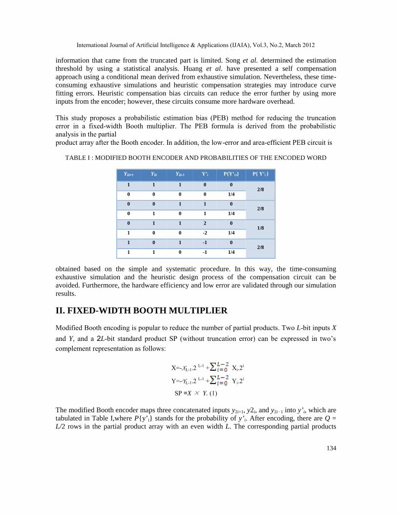
TABLE I : MODIFIED BOOTH ENCODER AND PROBABILITIES OF THE ENCODED WORD
Y2i+1 Y2i Y2i-1 Y’i P{Y’O} P{ Y’i }
1 1 1 0 02/8
0 0 0 0 1/4
0 0 1 1 02/8
0 1 0 1 1/4
0 1 1 2 01/8
1 0 0 -2 1/4
1 0 1 -1 02/8
1 1 0 -1 1/4
obtained based on the simple and systematic procedure. In this way, the time-consumingexhaustive simulation and the heuristic design process of the compensation circuit can beavoided. Furthermore, the hardware efficiency and low error are validated through our simulationresults.
II. FIXED-WIDTH BOOTH MULTIPLIER
Modified Booth encoding is popular to reduce the number of partial products. Two L-bit inputs X
and Y, and a 2L-bit standard product SP (without truncation error) can be expressed in two’scomplement representation as follows:
X=-XL-1.2 L-1 + Xi.2i
Y=-YL-1.2 L-1 + Yi.2i
SP =X× Y. (1)
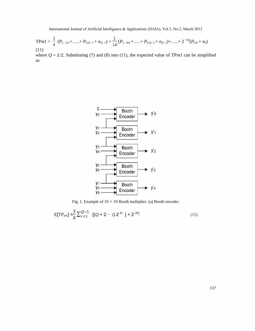
The modified Booth encoder maps three concatenated inputs y2i+1, y2i, and y2i−1 into y’i, which aretabulated in Table I,where P{y’i} stands for the probability of y’i. After encoding, there are Q =L/2 rows in the partial product array with an even width L. The corresponding partial products
International Journal of Artificial Intelligence & Applications (IJAIA), Vol.3, No.2, March 2012
135
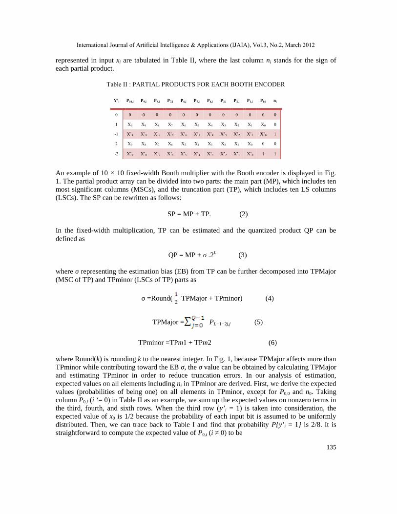
represented in input xi are tabulated in Table II, where the last column ni stands for the sign ofeach partial product.
Table II : PARTIAL PRODUCTS FOR EACH BOOTH ENCODER
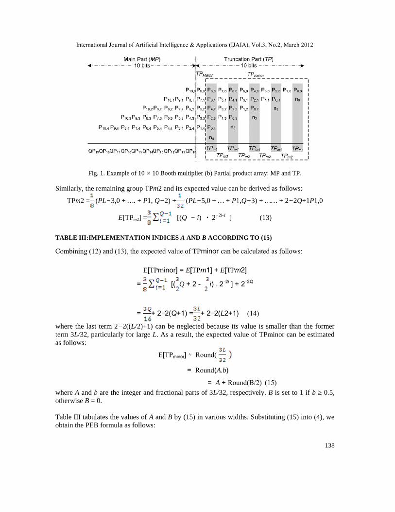
An example of 10 × 10 fixed-width Booth multiplier with the Booth encoder is displayed in Fig.1. The partial product array can be divided into two parts: the main part (MP), which includes tenmost significant columns (MSCs), and the truncation part (TP), which includes ten LS columns(LSCs). The SP can be rewritten as follows:
SP = MP + TP. (2)
In the fixed-width multiplication, TP can be estimated and the quantized product QP can bedefined as
QP = MP + σ .2L (3)
where σ representing the estimation bias (EB) from TP can be further decomposed into TPMajor(MSC of TP) and TPminor (LSCs of TP) parts as
σ =Round( TPMajor + TPminor) (4)
TPMajor = PL−1−2j,j (5)
TPminor =TPm1 + TPm2 (6)
where Round(k) is rounding k to the nearest integer. In Fig. 1, because TPMajor affects more thanTPminor while contributing toward the EB σ, the σ value can be obtained by calculating TPMajorand estimating TPminor in order to reduce truncation errors. In our analysis of estimation,expected values on all elements including ni in TPminor are derived. First, we derive the expectedvalues (probabilities of being one) on all elements in TPminor, except for P0,0 and n0. Takingcolumn P0,i (i ‘= 0) in Table II as an example, we sum up the expected values on nonzero terms inthe third, fourth, and sixth rows. When the third row (y’i = 1) is taken into consideration, theexpected value of x0 is 1/2 because the probability of each input bit is assumed to be uniformlydistributed. Then, we can trace back to Table I and find that probability P{y’i = 1} is 2/8. It isstraightforward to compute the expected value of P0,i (i ≠ 0) to be
International Journal of Artificial Intelligence & Applications (IJAIA), Vol.3, No.2, March 2012
136
E[P0,i]= P{P0,i=1|yi’=k}.P{yi’=k}
=
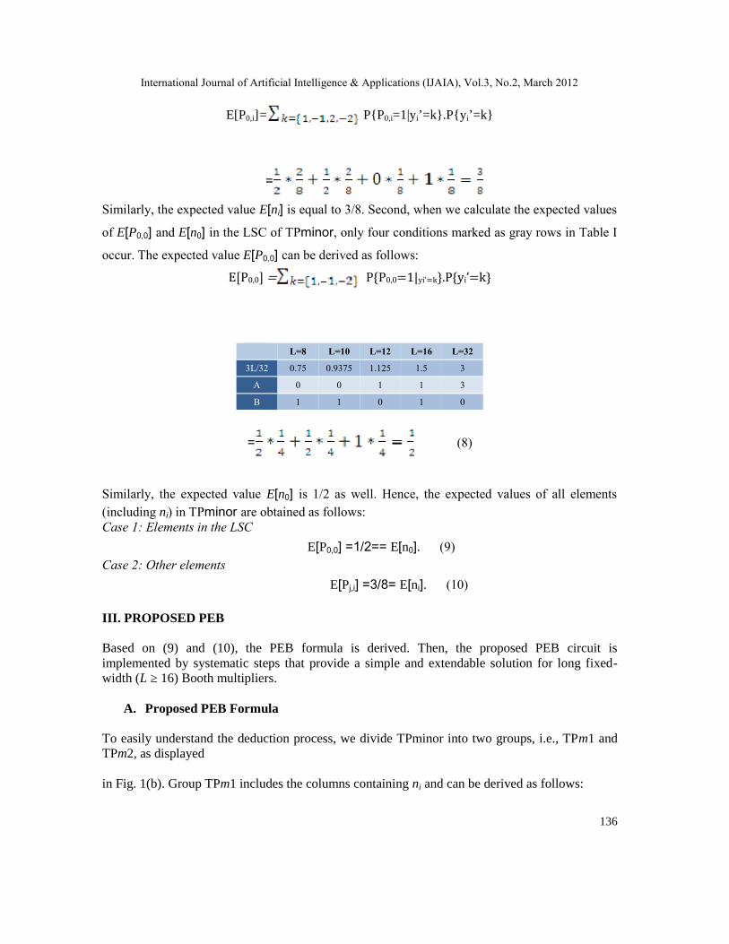
Similarly, the expected value E[ni] is equal to 3/8. Second, when we calculate the expected values
of E[P0,0] and E[n0] in the LSC of TPminor, only four conditions marked as gray rows in Table I
occur. The expected value E[P0,0] can be derived as follows:E[P0,0]= P{P0,0=1|yi’=k}.P{yi’=k}
= (8)
Similarly, the expected value E[n0] is 1/2 as well. Hence, the expected values of all elements(including ni) in TPminor are obtained as follows:Case 1: Elements in the LSC
E[P0,0] =1/2== E[n0]. (9)Case 2: Other elements
E[Pj,i] =3/8= E[ni]. (10)
III. PROPOSED PEB
Based on (9) and (10), the PEB formula is derived. Then, the proposed PEB circuit isimplemented by systematic steps that provide a simple and extendable solution for long fixed-width (L ≥ 16) Booth multipliers.
A. Proposed PEB Formula
To easily understand the deduction process, we divide TPminor into two groups, i.e., TPm1 andTPm2, as displayed
in Fig. 1(b). Group TPm1 includes the columns containing ni and can be derived as follows:
L=8 L=10 L=12 L=16 L=32
3L/32 0.75 0.9375 1.125 1.5 3
A 0 0 1 1 3
B 1 1 0 1 0
International Journal of Artificial Intelligence & Applications (IJAIA), Vol.3, No.2, March 2012
TABLE III:IMPLEMENTATION INDICES A AND B ACCORDING TO (15)
Combining (12) and (13), the expected value of TPminor can be calculated as follows:
E[TPminor] = E[TPm1] + E[TPm2]
= [( Q + 2 - i) .2−2i ] + 2−2Q
= + 2−2(Q+1) = + 2−2(L2+1) (14)
where the last term 2−2((L/2)+1) can be neglected because its value is smaller than the formerterm 3L/32, particularly for large L. As a result, the expected value of TPminor can be estimatedas follows:
E[TPminor] ≈ Round(
= Round(A.b)= A + Round(B/2) (15)
where A and b are the integer and fractional parts of 3L/32, respectively. B is set to 1 if b ≥ 0.5,otherwise B = 0.
Table III tabulates the values of A and B by (15) in various widths. Substituting (15) into (4), weobtain the PEB formula as follows:
International Journal of Artificial Intelligence & Applications (IJAIA), Vol.3, No.2, March 2012
139
σ =Round( TP Major + )
=Round( (TP Major + B)) + A . (16)
B. Proposed PEB Circuit Using the Systematic Procedure
The realization of (16) can be easily implemented by using full adders (FAs) and half-adders(HAs). The PEB circuit is obtained after the following systematic steps:1) Find integer A and bit B by calculating PEB in (15).2) Generate A estimation carries (ec0 − ecA−1), and add them to the LSC of MP.3) Sum up bit B and elements in set {TPMajor} = {PL−1,0, PL−3,1, . . . , P1,Q−1} with the FAor HA tree to produce the remaining estimation carries (ecis) being added to the LSC of MP and asum (for rounding). The detailed procedure is listed as follows:
a) Add bit B and set {TPMajor} in the carry-save form [16] with sums to be repeatedly added forproducing ecis until only one sum is left.
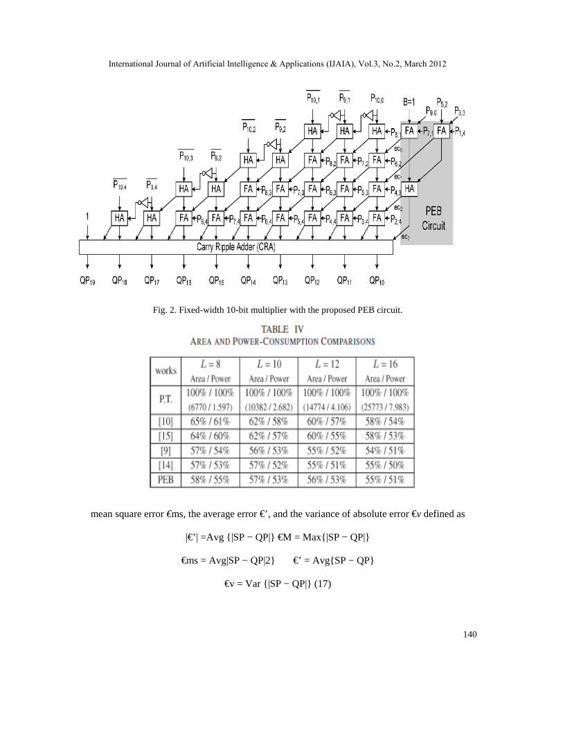
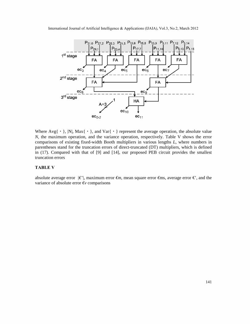
b) Set the final sum as the last eci.Taking width L = 10 as an example, the proposed PEB circuit(gray block as shown in Fig. 2) can be obtained after conducting the proposed systematic steps.First, A = 0 and B = 1 are obtained from Table III. Second, no carry is generated because A = 0.Third, sum up B (= 1) and all elements of set {TPMajor} = {P9,0, P7,1, P5,2, P3,3, P1,4} withtwo FAs and one HA. The 10-bit Booth multiplier with the proposed PEB circuit is shown in Fig.2. The systematic steps can be applied to the long fixed-width multiplication. For example, Fig. 3displays the PEB circuit for the 32-bit fixed-width multiplication (A =3 & B = 0).
IV. PERFORMANCE COMPARISONS
A. Fixed-Width Booth Multiplier
In Table IV, Cadence System-on-Chip (SoC) Encounter is applied with Taiwan SemiconductorManufacturing Company (TSMC) 0.18-μm standard cell library to implement all the listedcircuits, and the area (in square micrometers) and power consumption (in milli watts)comparisons are normalized to those of the post truncated Booth multipliers as shown inparentheses, respectively. The accuracy can be evaluated in terms of the absolute average error|€’|, the maximum error €M,
International Journal of Artificial Intelligence & Applications (IJAIA), Vol.3, No.2, March 2012
140
Fig. 2. Fixed-width 10-bit multiplier with the proposed PEB circuit.
mean square error €ms, the average error €’, and the variance of absolute error €v defined as
|€’| =Avg {|SP − QP|} €M = Max{|SP − QP|}
€ms = Avg|SP − QP|2} €’ = Avg{SP − QP}
€v = Var {|SP − QP|} (17)
International Journal of Artificial Intelligence & Applications (IJAIA), Vol.3, No.2, March 2012
141
Where Avg{・}, |N|, Max{・}, and Var{・} represent the average operation, the absolute valueN, the maximum operation, and the variance operation, respectively. Table V shows the errorcomparisons of existing fixed-width Booth multipliers in various lengths L, where numbers inparentheses stand for the truncation errors of direct-truncated (DT) multipliers, which is definedin (17). Compared with that of [9] and [14], our proposed PEB circuit provides the smallesttruncation errors
TABLE V
absolute average error |€’|, maximum error €m, mean square error €ms, average error €’, and thevariance of absolute error €v comparisons
International Journal of Artificial Intelligence & Applications (IJAIA), Vol.3, No.2, March 2012
142
except the average error with the same or 1% more hardware overhead. It is also interesting toobserve that the designs of [10] and [15] outperform [9], [14], and our proposed PEB circuit inthese error merits using more hardware. In general, a tradeoff exists between hardware overheadand accuracy in these compensation circuits. The larger hardware overheads of [10] and [15]come from the bias generation circuits and encoders. Because our compensation bias is derivedfrom a theoretical deduction, our PEB circuit could be easily extended
TABLE VI
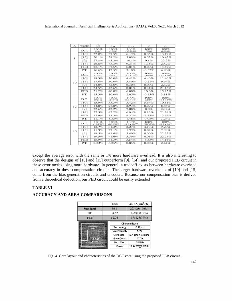
ACCURACY AND AREA COMPARISONS
PSNR AREA µm2 (%)Standard 56.1 223428(100%)
DT 34.62 166919(75%)PEB 52.04 171825(77%)
Fig. 4. Core layout and characteristics of the DCT core using the proposed PEB circuit.
International Journal of Artificial Intelligence & Applications (IJAIA), Vol.3, No.2, March 2012
143
for high-accuracy fixed-width multiplication using more information from TPminor with thepenalty of more area. Different from previous compensation circuits for Booth multipliers, ourPEB circuit does not need the exhaustive simulation and the heuristic bias circuit design.
B. Application Example: DCT
In order to exhibit the accuracy in real applications, the proposed low-error PEB is applied into an8×8 2-DDCT [17]. The size of the test image “Lena” is 512×512 pixels, with each pixel beingrepresented by 8-bit 256-gray-level data. Moreover, the accuracy performance of the DCT core isevaluated by the peak signal-to-noise ratio (PSNR). The comparison results for the accuracy ofthe PSNR and the synthesized area are tabulated in Table VI. Compared with the DCT core usingstandard Booth multipliers, the DCT core using the proposed PEB circuit reduces 23% area withthe PSNR penalty of 4 dB. On the other hand, the accuracy the PSNR of the DCT core using theproposed PEB circuit is more than 17 dB, which is larger than the DT approach with only2%more hardware overhead. To implement the DCT with the proposed PEB circuit on a chip, weuse the Synopsys Design Compiler to synthesize the register-transfer-level design and CadenceSoC Encounter to run placement and routing. Fig. 4 shows the layout view and the characteristicsof the architecture. While implemented in a 1.8-V TSMC 0.18-μm 1P6M CMOS process, theproposed DCT core can be operated in a 55 MHz clock rate, and the core size is 501μm×508μm.
V. CONCLUSION
In this brief, we have first derived the PEB formula and have applied the probabilistic analysis forthe truncated two’s complement fixed-width Booth multiplier. Then, a simple and systematicprocedure has been presented to design the compensation circuit based on the PEB formula andthe probabilistic analysis. Compared with the existing works, the proposed method has providedsmaller area and smaller truncation errors. The realization of our PEB circuit does not needexhaustive simulations and heuristic compensation strategies that tend to introduce curve fittingerrors and unacceptable exponential simulation time. Furthermore, the proposed PEB Boothmultiplier in the DCT application has shown the improvement of the PSNR by 17 dB with only2% area penalty compared with the DT method. In the future work, our PEB circuit can beapplied for high-accuracy fixed-width multiplication using more inputs from TPminor with morehardware overhead.
REFERENCES
[1] J. P. Wang, S. R. Kuang, and S. C. Liang, “High-accuracy fixedwidth modified Booth multipliers forlossy applications,” IEEE Trans.Very Large Scale Integr. (VLSI) Syst., vol. 19, no. 1, pp. 52–60, Jan.2011.
[2] M. J. Schulte and E. E. Swartzlander, Jr., “Truncated multiplication with correction constant,” inVLSI Symp. Tech. Dig., 1993, pp. 388–396.
[3] S. S. Kidambi, F. El-Guibaly, and A. Antoniou, “Area-efficient multipliers for digital signalprocessing applications,” IEEE Trans. Circuits Syst. II,Analog Digit. Signal Process, vol. 43, no. 2, pp. 90–95, Feb. 1996.
[4] J. M. Jou, S. R. Kuang, and R. D. Chen, “Design of lower-error fixedwidth multipliers for DSPapplications,” IEEE Trans. Circuits Syst. II,Analog Digit. Signal Process, vol. 46, no. 6, pp. 836–842, Jun. 1999.
International Journal of Artificial Intelligence & Applications (IJAIA), Vol.3, No.2, March 2012
144
[5] L. D. Van, S. S. Wang, and W. S. Feng, “Design of the lower-error fixedwidth multiplier and itsapplication,” IEEE Trans. Circuits Syst. II, Analog Digit. Signal Process, vol. 47, no. 10, pp. 1112–1118, Oct. 2000.
[6] L. D. Van and C. C. Yang, “Generalized low-error area-efficient fixedwidth multipliers,” IEEE Trans.Circuits Syst. I, Reg. Papers, vol. 52,no. 8, pp. 1608–1619, Aug. 2005.
[7] Y. C. Liao, H. C. Chang, and C. W. Liu, “Carry estimation for two’s complement fixed-widthmultipliers,” in Proc. IEEE Workshop on SignalProcess. Syst. Design Implementation, 2006, pp. 345–350.
[8] N. Petra, D. D. Caro, V. Garofalo, E. Napoli, and A. G. M. Strollo, “Truncated binary multipliers withvariable correction and minimum meansquare error,” IEEE Trans. Circuits Syst. I, Reg. Papers, vol. 57, no. 6, pp. 1312–1325, Jun. 2010.
[9] S. J. Jou, M. H. Tsai, and Y. L. Tsao, “Low-error reduced-width Booth multipliers for DSPapplications,” IEEE Trans. Circuits Syst. I, Fundam. Theory Appl., vol. 50, no. 11, pp. 1470–1474,Nov. 2003.
[10] K. J. Cho, K. C. Lee, J. G. Chung, and K. K. Parhi, “Design of low-error fixed-width modified Boothmultiplier,” IEEE Trans. Very Large Scale Integr. (VLSI) Syst., vol. 12, no. 5, pp. 522–531, May2004.
[11] T. B. Juang and S. F. Hsiao, “Low-error carry-free fixed-width multipliers with low-costcompensation circuits,” IEEE Trans. Circuits Syst. II, Exp.Briefs, vol. 52, no. 6, pp. 299–303, Jun.2005.
[12] K. K. Parhi, J. G. Chung, K. C. Lee, and K. J. Cho, “Low-error fixed-width modified Boothmultiplier,” U.S. Patent 7 334 200, Feb. 19, 2008.
[13] H. A. Huang, Y. C. Liao, and H. C. Chang, “A self-compensation fixedwidth Booth multiplier and its128-point FFT applications,” in Proc. IEEE ISCAS, 2006, pp. 3538–3541.
[14] M. A. Song, L. D. Van, and S. Y. Kuo, “Adaptive low-error fixed-width Booth multipliers,” IEICETrans. Fundam., vol. E90-A, no. 6, pp. 1180– 1187, Jun. 2007.
[15] Y. C. Lim, “Single-precision multiplier with reduced circuit complexity for signal processingapplications,” IEEE Trans. Comput., vol. 41, no. 10, pp. 1333–1336, Oct. 1992
[16] B. Parhami, Computer Arithmetic: Algorithms and Hardware Designs.. Oxford, U.K.: Oxford Univ.Press, 2000.
[17] S. C. Hsia and S. H. Wang, “Shift-register-based data transposition for cost-effective discrete cosinetransform,” IEEE Trans. Very Large Scale Integr. (VLSI) Syst., vol. 15, no. 6, pp. 725–728, Jun.2007.