HF COMMUNICATION GENERAL Two High Frequency (HF) radio systems are used to transmit and receive voice communications. They are used primarily for long range communica- tions outside the range of other systems. Long range communication is pos- sible since this system is not limited by line-of-sight characteristics. This system not only provides the conventional Amplitude Modulation (.AJ.'\1) method of communications but also the more recent Sideband (SSB) method. This too enhances the longer range capability of the system. Am.CRAFT INSTALLATION Each system consists of a Model"618T-2 transceiver, a }lodel 180 R-4A an- tenna coupler, a 309A-1A coupler accessory unit, a 452A-1A lightning ar- restor relay unit, a Model 714E-2A Control Panel, and one rod type fixed antenna shared by both systems. transcei•:ers are in tl:e cer:ter avionics equipment rack. Tt.:= contrcl panels are 'Jn the ce:::.:er console; t.1e accessory .. ; a=e 1r: :::e ver::- cal stabilizer base; and the lightning arrestor relay unit and coup•ers are in the horizontal stabilizer bullet. The antenna is mounted in the forw·ard bullet fairing of the empennage. Primary power necessary for system operation is 25-volt D-C power and 3- phase AC, 2 08 volts, phasa-to-phase. Four circuit breakers for each system are on the avionics circuit breaker panel. System No. l supplied from the A-C avionics and main D-C avionics No. 1 busses. No. 2 HF is supplied in a:1 identical manner from the No. 2 busses. Keying inte:dock between the two HF systems is provided by relays in the cou- pler accessory units and the lig!J.tning_arrestor relay_ unit. The interlock circuits prevent both transceivers from being keyed simultaneously, and pro- vide the necessary switching to enable one antenna to be used by both systems. VOL. VI 4-1 '·
Transcript
HF COMMUNICATION
GENERAL
Two High Frequency (HF) radio systems are used to transmit and receive voice communications. They are used primarily for long range communications outside the range of other systems. Long range communication is possible since this system is not limited by line-of-sight characteristics. This system not only provides the conventional Amplitude Modulation (.AJ.'\1) method of v~~ce communications but also the more recent Sing!~ Sideband (SSB) method. This too enhances the longer range capability of the system.
Am.CRAFT INSTALLATION
Each system consists of a Model"618T-2 transceiver, a }lodel 180 R-4A antenna coupler, a 309A-1A coupler accessory unit, a 452A-1A lightning arrestor relay unit, a Model 714E-2A Control Panel, and one rod type fixed antenna shared by both systems.
-=-~e transcei•:ers are in tl:e cer:ter avionics equipment rack. Tt.:= contrcl panels are 'Jn the ce:::.:er console; t.1e ~m:pler accessory un~ .. ; a=e 1r: :::e ver::cal stabilizer base; and the lightning arrestor relay unit and an~:1na coup•ers are in the horizontal stabilizer bullet. The antenna is mounted in the forw·ard bullet fairing of the empennage.
Primary power necessary for system operation is 25-volt D-C power and 3-phase AC, 2 08 volts, phasa-to-phase. Four circuit breakers for each system are on the avionics circuit breaker panel. System No. l ~ supplied from the A-C avionics and main D-C avionics No. 1 busses. No. 2 HF is supplied in a:1 identical manner from the No. 2 busses.
Keying inte:dock between the two HF systems is provided by relays in the coupler accessory units and the lig!J.tning_arrestor relay_ unit. The interlock circuits prevent both transceivers from being keyed simultaneously, and provide the necessary switching to enable one antenna to be used by both systems.
VOL. VI 4-1 '·
.· (.
:
< 0 t"" .
. {~ AC AVIONICS ,.-L..... BUS t~o. 1 -6 5A l>--
MAIN - 5A DC AVIONICS ~
BUS No.1 --07A ~
MAIN DC AVIONICS
BUS No.2
COUPLER No.1
CABIN PRESSURE
uu ·{ ()
u > 100)
~(\J ... ILU
z n.._
AVIONICS CIRCUIT BREAKER PANEl. (.t.LL Hf CIRCUIT
BREAKERS) .
~: TRANSCEIVERS LOCATED ON RIGHT SIDE
CENTER AVIONICS RACK.
TRANSCEIVERS
INSTALLATION
fLIGHT STATION CENTER
CONSOLE
LIGHTNING ARIUSTOR
No.1 AND No.2
--··
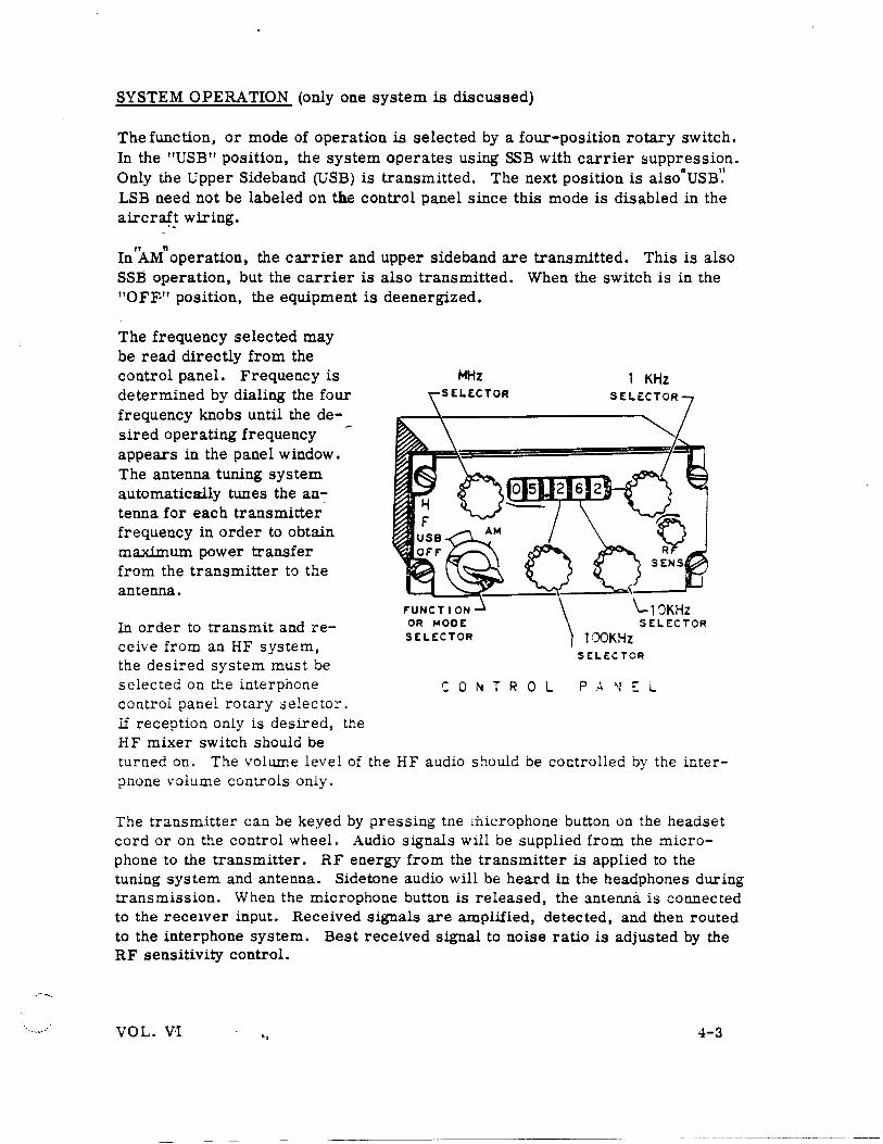
SYSTEM OPERATION (only one system is discussed)
The function, or mode of operation is selected by a four-position rotary switch. In the "USB" position, the system operates using SSB with carrier suppression. Only the Upper Sideband (USB) is transmitted. The next position is alsonUSB'.' LSB need not be labeled on the control panel since this mode is disabled in the aircr~~ wiring.
" " In AM operation, the carrier and upper sideband are transmitted. This is also SSB operation, but the carrier is also transmitted. When the switch is in the "OFF·" position, the equipment is deenergized.
The frequency selected may be read directly from the control panel. Frequency is determined by dialing the four frequency knobs until the desired operating frequency appears in the panel window. The antenna tuning system automatically tunes the an-:tenna for each transmitter frequency in order to obtain maximum power transfer from the transmitter to the antenna.
In order to transmit and receive from an HF system, the desired system must be selected on t...l:e interphone control panel rotary selector. If reception only is desired, the HF mixer switch should be
MHz 1 KHz
\_10KHz OR ~ODE SE~ECTOR
St~ECTOR 100KHz SE:~ECTOR
C 0 N T R 0 L P A ~ ~ L
turned on. The volume level of the HF audio should be controlled by the inter-pnone •·olume controls only.
The transm.itter can be keyed by pressing tne rnicrophone button on the headset cord or on the control wheel. Audio signals will be supplied from the microphone to the transmitter. RF energy from the transmitter is applied to the tuning system and antenna. Sidetone audio will be heard in the headphones during transmission. When the microphone button is released, the antenna is connected to the rece1ver input. Received signals are amplified, detected, and then routed to the interphone system. Best received signal to noise ratio is adjusted by the RF sensitivity control.
VOL. V·I .. 4-3
When each new frequency is selected and the transmitter is first keyed, the antenna tuning system will tune. The tuning cycle is indicated to the operator
CONTROL .. PANEL
MIC
F'REQUENCY SELECTION
AND CONTROL
TRANSCEIVER
HEADSET KEY AUDIO (PTT)
INTERPHONE CONTROL PANEL
·I~ MIC BUTTON
MIC AUDIO
SYSTEM 8 L 0 C K
ANTENNA TUNING SYSTEM
COUPLER AND ACCESSORY UNIT
HEADPHONES
D I A G R A M
by a 1KHz tone in the headphones. The average tuning time of the tuning system is five seconds. When tuning is complete, the tone will cease. Keying the transmitter the second time will provide full power transmission. This operation is known as "Radio Silence" meaning that the transmitter is not on the air for tuning purposes until the transmitter is first keyed. This reduces needless tr:l;::smissions that cause interference when new receive frequencies are selected. I! the system fails to tune in 75 seconds, a thermal cutcut will disable the t:.ming cycle and prev-:mt transmission. After allowing coolin6 ti.:-::e, a new .:reqt.:enc? must be selected and the :::::ic buttTn. p!"essed i:J. ,Jrcer :o i.::i:i.::.:e tt.? ~~::i:.:; ,::::,_2 again..
During receive operation, the antenna is connected directly to an an:plifier in tb.e accessory unit, bypassing the tuning circuits in ::he cot~pler used ::!tU"i::g ~'..:.!li~;
and transmit operations. The amplifier output is supplied to the receiver.
4-4 VOL. VI ..
•,__/'
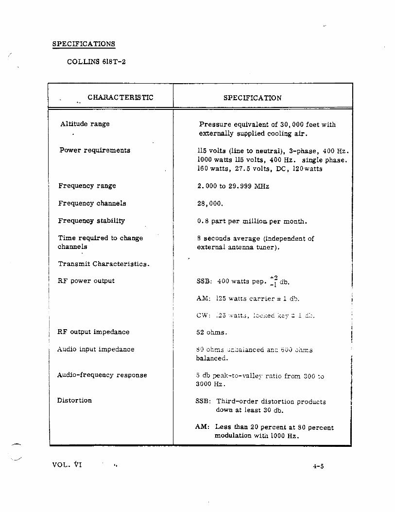
SPECIFICATIONS
COLLINS 618T-2
CHARACTERISTIC
Altitude range
Power requirements
Frequency range
Frequency channels
Frequency stability
Time required to change channels
Transmit Characteristics.
RF power output
RF output impedance
Audio input impedance
Audio-frequency response
Distortion
VOL. VI ..
SPECIFICATION
Pressure equivalent of 30, 000 feet with externally supplied cooling air.
115 volts (line to neutral), 3-phase, 400 Hz. 1000 watts 115 volts, 400Hz. single phase. 160 watts, 27.5 volts, DC, 120watts
2. 000 to 29.999 MHz
28,000.
0. 8 part per million per month.
8 seconds average (independent of external antenna tuner).
....., SSB: 400 watts pep. -i db.
AM: 125 watts carrier± 1 db.
CW:
52 ohms.
80 ohms u~jaianced anc.: 600 0h.n:s balanced .
.5 db peak-to-valley ratio from 300 to 3000Hz.
SSB: Third-order distortion products down at least 30 db.
AM: Less than 20 percent at 80 percent modulation with 1000 Hz.
4-5
SPECIFICATIONS (Continued)
COLLINS 618T-2
CHARACTERISTIC
Receive Characteristics.
Sensitivity
Selectivity
A.GC characteristic
IF and image rejection
Audio output power
Audio distortion
. :..1C:J.o-!reque:1cy res~on.se
Image rejection
4-6 .,
SPEC !FICA TION
SSB: 1 microvolt for 10 db S+N/N ratio.
AM: 3 microvolts modulated 30 percent 1000 Hz for a 6 db S+N/N ratio.
SSB: 2. 85KHz, 6 db dmvn. 6. 0 KHz, 60 db down.
AM: 5.5 KHz, 6 db down. 14.0 KHz, minimum, 60 db down.
Maximum variation of audio putput is 6 db for input signals from 10 to 100,000 microvolts. No overload below 1-volt signal input.
5 c!..j ~:.~~~~-!o-\·J.!le:,: !~~;.L:io ~Z"Ol:l 3GO tv 3000 Hz.
60 db mini.r.nun below desired frequency relative to 5 microvolt input.
VOL. VI
MODULE FUNCTION
·- Al Frequency divider
A2 RF oscillator
A3 IF translator
A4 Kilohertz-frequency stabilizer
AS Low-voltage power supply
A6 Electronic control amplifier
A7 3 phase AC high-voltage power supply
-:--:-A9 '
AM/ audio amplifier·
AlO Megahertz-frequency stabilizer
All ~ Power amplifier
Al2 RF translator
Al2Al Autopositioner (submodule)
Al2A2 I Variable-f!"equency oscillator (VFO
I submodule)
. .-
VOL• VI 4-7 ..
.... ·
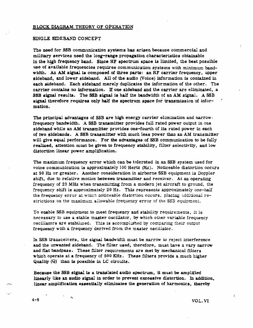
BLOCK DIAGRAM THEORY OF OPERATION
SINGLE SIDEBAND CONCEPT
The need for SSB communication systems has arisen because commercial and military services need the long-range propagation characteristics obtainable in the ~h frequency band. Since HF spectrum space is limited, the best possible use of available frequencies requires communication systems with minimum bandwidth. An AM signaliJJ composed of three parts: an RF carrier frequency, upper sideband, and lower sideband. All of the audio (Voice) information is contained in each sideband. Each sideband merely duplicates the information of the other. The carrier contains no information. If one sideband and the carrier are eliminated, a SSB siinal results. The SSB signal is half the bandwidth of an AM signal. A SSB signal therefore requires only half the spectrum space for transmission of information.
The principal advantages of SSB are high energy carrier elimination and narrow· frequency bandwidth. A SSB transmitter provides full rated power output in one sideband while an AM transmitter provides one-fourth of ita rated power in each of two sidebands. A SSB transmitter with much less power than an AM transmitter will give equal performance. For the advantages of SSB communication to be fully realized, attention must be given to frequency stability, filter selectivity, and low distortion linear power amplification.
The maximum frequency error which can be tolerated in an SSB system used for voice communication is approximately 100 Hertz (Hz). Noticeable distortion occurs at 50 Hz or greater. Another consideration in airborne SSB equipment is Doppler shift, due to relative motion between transmitter and receiver. At an operating frequency of 20 MHz when transmitting from a modern jet aircraft to ground, the frequency shift is approximately 2 0 Hz. This represents approximately one-half the frequency error at whic!l noticeable distortion occurs, placing :dditional restrictions on the maximum allowable frequency error of the SSB equipmer.t.
To enable SSB equipment to meet frequency and stability requirements, it is necessary to use a stable master oscillator, by which other variable frequency oscillators are stabilized. This is accompl~hed by comparing their output frequency with a frequency derived from the master oscillator.
In SSB transceivers, the signal bandwidth must be narrow to reject interference and the unwanted sideband. The filter used, therefore, must have a vary narrow and flat bandpass. These filter requirements are met by mechanical filters which operate at a frequency cf 500 KHz. These filters provide a. much higher Quality (Q) than is possible in LC circuits.
Because the SSB signal is a translated audio spectrum, it must be amplified linearly like an audio signal in order to prevent excessive distortion. In addition, linear amplification essentially eliminates the generation of harmonics, thereby
4-8 VOL. VI
preventing adjacent channel interference. Class C RF am·plifiers, like those used to amplify AM signals, therefore, cannot be used in SSB transmissions. The RF amplifiers and drivers are usually pentode vacuum tube stages operating class A.
The SSB signal is generated in the HF communication system by a filter-type SSB generator, consisting of a balanced modulator and a very selective bandpass filter. Th~ output amplitude of the balanced modulator depends on the audio input amplitude. When there is no audio input, the balanced modulator has no output.
501KHz USB~
499f(Hz LSB ~ USB 501KHz
A
s UDIO I GN.AL__j I!IALANC£0 I
1KHz l MODUL.ATO,_ j
IF' SIGNAL
500KHz·
MECHANICAL F'ILTER
~501KHz USB ~ PLUS
~ 499KHz LSB
MNV\
1 500-503KHz
I!I.ANDPASS
-CARR.I £R REINSERT
Using a 500 KHz signal as the carrier frequency and a 1000 Hz audio tone as inputs, the output of the balanced modulator consists of the upper and lower sidebands, one on each side of 500 KHz,just as in an AM modulator. Unlike an AM modulator output however, the balanced modulator contains no appreciable amount of the 500 KHz carrier component. Thus, the carrier has been suppressed.
The double-sideband, suppressed-carrier signal (501 KHz and 499 KI-!z) from the balanced modulator is fed to an upper sideband (USB) mechanical filter. The bandwidth of the filter is 3KHz; wide enough to pass only the mod~lating spectrum. Therefore, only the upper sideband will be passed (501 KHz). Note that the SSB signal is a sine wave, constant in amplitude, when a single-:one audio signal is used for modulation. This SSB signal is displaced from its original carrier frequency by an amount equal to the frequency of the modulating audio signal. This modulated signal is heterodyned in several mixers until the selected transmitter frequency has been developed.
To recover the audio signal at the receiver, the SSB signal must be mixed wi~ a carrier frequency which is generated at the receiver. The mixer- that performs this demodulation is called a product detector. In the example given, combining 501KHz with 500 KHz (carrier signal) in the product detector produces a difference frequency of 1KHz, which is the .audio signal.
VOL. VI .. 4-9
Remember that in the transmitter, the carrier is suppressed and the sideband is transmitted. In the receiver, the sideband is received and the carrier reinserted.
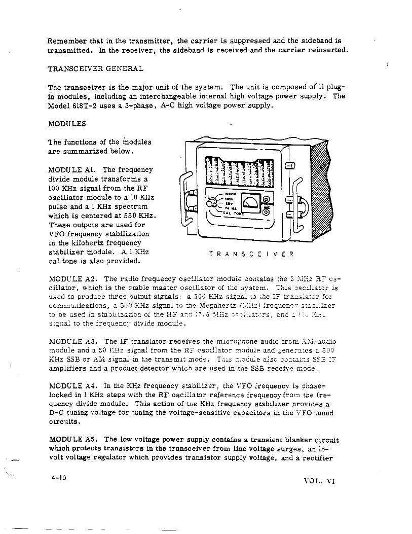
TRANSCEIVER GENERAL
The transceiver is the major unit of the system. The unit is composed of 11 plugin modules, including an interchangeable internal high voltage power supply. The Model 6l8T-2 uses a 3-phase, A-C high voltage power supply.
MODULES
1 he functions of the modules are summarized below.
MODULE Al. The frequency divide module transforms a 100KHz signal from the RF oscillator module to a 10 KHz pulse and a 1KHz spectrum which is centered at 550KHz. These outputs are used for VFO frequency stabilization in the kilohertz frequency stabilizer module. A 1KHz cal tone is also provided.
T R A N S C ~ I V ~ R
MOD1:LE A2. The radio frequency oscillator module ~outains the ~ .:-.m.z .il:? oscillator, which is the stable master oscillator of t::e :>ystem. This :)SC~l.i.ator is used to produce three output signals: a 500 KHz sig::u:..l > • .:> ;:.he :F t:-2-::J..s:a:o:: for comr:1unicatio:1s, a 500 KHz signal to :l:e ::\1.egahe!'tz c,:~-.!..:: ,1 frequer:~·· s :.::t::J~~iz.er to be usee i::l stajiliz.:l;:ic:J. of the HF a::cl :7.5 ~\I!-iz :;·~:~~:~a:;::::-s, :1nC: _ i:v •,:~-:-
s :~nal to the frequenc:: cliv ide module.
MODl:: LE A3. The IF translator receives the mic::-otJhone audio frorr.. A.:\1; aucio ~'Jdule and a 50 IC...'"!z signal froo the R? cscillator !l':odule and b'ene:-ates a 500 KHz SSE or A.:r1 signal in tae transml~ ;:node. 'L1.;..:; ::.or~tLe a~~e; co::t.:>.i::3 SS3 :r amplifiers and a product detector which are used in the SSE receive mode.
MODuLE A4. In the KHz frequency stabilizer, the VFO Irequency is phaselocked in 1 KHz steps with the RF oscillator reference frequency f!"om t.b.e frequency divide module. This action of tr•e KHz frequency stabilizer provides a D-C tuning voltage for tuning the voltage-sensitive capacitors in the VFO tuned circuits.
MODULE AS. The low voltage power supply contains a transient blanker circuit which protects transistors in the transceiver from line voltage surges, an 18-volt voltage regulator which provides transistor supply voltage, and a rectifier
4-10 VOL. VI
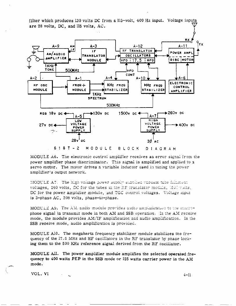
filter which produces 130 volts DC from a 115-volt, 400 Hz input. are 28 volts, DC, and 115 volts, AC.
Voltage inputs
w ..J
500KHz
A-2
Rf' OSC MODULE
REG 18v DC
27v OC+---1
A-1 F'REQ + MODULE
LOW VOLTAGE
POWER SlJPPl.Y
28v oc
A-3
1KHz SPECTRUM
500KHz
130v oc 1 500v DC
618T-2 MODULE 8 L 0 C K
F'REQ
STAS II. I ZER
I 3¢ AC
--.,.--DISC •MOTOR
A-6 ELECTRONIC
CONTROL AMPLIF'IER
260v DC
1---• 400v oc
DIAGRAM
MODULE A6. Tne electronic control :..mplifier receives an error sig::1ai from tl:e power amplifier phase discriminator. This signal is amplified and applied to :1
servo motor. The :::notor drives a variable inductor used b tuning t!:e pov.·er amplifier's output network.
voltages, 260 volts, DC for the tubes 1:: ~r.e EF ::-ar:3lJ.t:.:· ~1oC::..::e, :_::, ~<· ': _,..:s, DC for the power amplifier module, and TGC controL voltages. \"::Jl:a.ge mput is 3-phase AC, 208 volts, phase-to-phase.
phone signal in transmit mode in both AM and SSB operation. In ~he AM receive mode, the module provides A1.1/IF amplification and audio amplification. In the SSB receive mode, audio amplific:ltion is provided.
MODULE AlO. The megahertz frequency stabilizer module stabilizes the f::-equency of the 17.5 11Hz and HF oscillators in the RF translator by phase locking them to the 500 KHz reference signal derived from the RF oscillator.
MODULE All. The power amplifier module amplifies the selected operated frequency to 400 watts PEP in the SSB mode or 125 watts carrier power in the AM mode.
VOL. VI .. 4-11
· ..
MODULE Al2. The RF translator contains the VFO and 17. 5 MHz and HF oscil.lators with their associated transmit and receive mixers. These circuits are used in translating the 500 KHz modulated IF signal to the selected operating frequency in the transmit mode and translating the received RF signal into the 500KHz IF signal in the receive mode.
Color coded test points located on the modules permit general troubleshooting w-ithout removing modules from the chassis. Each module is equipped with plugin connectors and can be quickly removed since there are no mechanical linkages between any of the modules. Many of the potentiometer adjustments are also acce~sible without removing modules from the unit. Headset and microphone jacks, meter, and meter selector switch are located on the front panel. Four meter selector switch positions are used to check power supply voltages and power amplifier plate current. A fifth position, "CAL TONE", is used to coml)are the frequency of the Model 618T-2 with WWV. A 400 Hz blower is also located on the front panel to provide forced-air cooling.
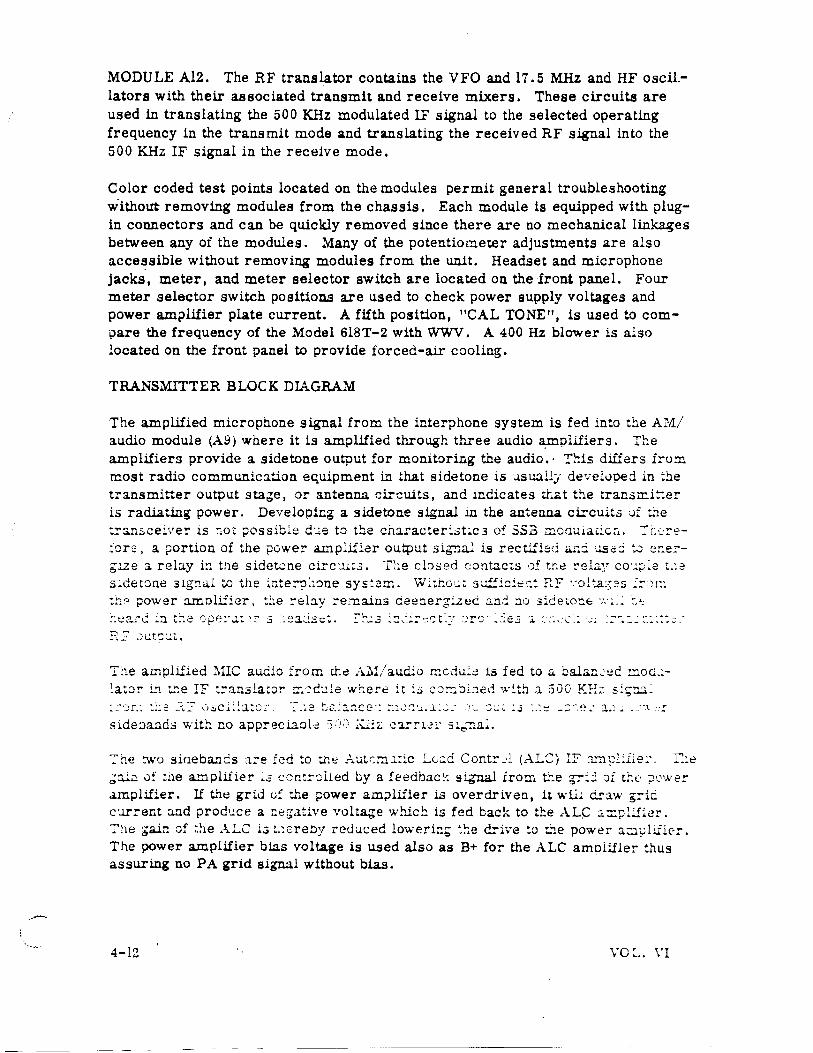
TRANSMITTER BLOCK DIAGRAM
The amplified microphone signal from the interphone system is fed into the AM/ audio module (A9) where it is amplified through three audio 3;-IDPllfiers. The amplifiers provide a sidetone output for monitoring the audio.· This diliers fro::n most radio communication equipment in that sidetone is J.SU:.lllj· de·.-eloped in :he transmitter output statie, or antenna circuits, and indicates tr.at the trans..-ni!::er is radiating power. Developing a sidetone signal in the antenna ci=cuits 0f t.'le :!'anscei-.·e-:- is ::oc ;;ossible d·.:.e to t!:::.e character:.;.>t:c3 of SS3 r:rwdu1acic~.. :"r:e:::.-e.:'ors, a portion of the power a..L."'lp:ifiar output sig;1al is rectified <U::i u.se::i ~ e::e:-gue a rel:l.y i:J. tne sidetcne circ'.l.i:..;. The cbsed contacts o£ tne ~ela~' cou;:;~e t.:.2
T~e amplified MIC audio from t.ha A.ll!/audio mcdul~ is fed to a bala!:.:ec mod,L~a~or 1!1 the IF t:-anslato~ !T~·:-~::1le where it i.5 c:J~~i.:J.ed '!,\ .. ~th a 500 K!-L: si:;:u~
~he :wo sinebands a:-e fed :o tile A.utt:r:lJ.:ic Lv;:d Contr_·l (AL8) IF ::un!-cLiie:·. r::e .;:ll..: 0£ :ne a.rJ.plifier ~3 ccnt:-:;lied by a feedbac!-: si.g"nal from t.l:e p-:.:: 'Jf the· ~c-Ner amplifier. If the grid (j: ±e ~ower am;>lifier is overdriven, it wli.;. cira.w griC c·-U'rent and prod•.lce a ~~gative volta;;e which is fed back to the ALC :1::::.:pl.:.fi<?r. T~1e ;a.in of ~~1e ALC i:i t.:creby reduced lo·-...·erin;; :!~e drive :o t.'le power a:::1pliiie:-. The power amplifier bias voltage is used also as B+ for the ALC amoliiler thus assuring no P A grid signal without bias.
4-12 vo~. n
The two sideband signals are further a~plified by a second IF amplifier and fed through a mechanical filter tuned to the Upper Sideband (USB) or Lower Sideband (LSB) depending on the mode selected on the control panel (disregard LSB which is disabled in the aircraft wiring).
AM/AUDIO MODULE
AUDIO AMPLS
S I DETONE
1-r TRANSLATOR MODULE I - - -- - -PT-- - - - - -- --;D;-T~ I ALC B lAS
I BALANCED
I MODULATOR
AUTO. LOAD
CONTROL AMPL
I AM I 1500 >-..... -+-----=-50::..0;;.:KH:.=...;.:z~r..:.;R;.;;o.;.;M_;,;.R;...F' _o;;..;s;;..;c;..._ ___ -o_.-IKHz o sse I ~- ------ -- -- -- ___ _j
TO RF' TRANSLATOR
MODULE
AU 0 I 0 T 0 F TRANSLATION SCHEME
T R A N S M I T )
When t!le transceiver is operated in the AM mode, the upper sideband is passed and a 500 KHz carrier from the RF oscillator module is reinserted at t.'le filter output producing an a.m.:>!itude-m::>dulated RF envelope.
The signa: is amplified fu!'ther by a third IF amplifier. The gain of th.is ampliii.C!r i3 co::.t=olled b:· feedbac:.. signal.:; fr::>m t!:e :Jower amplifier, This is accoo;Jlished oy a D-C n.l""l}li:ie.:::-. Ii excessive RF power amplifier plate-volta,::eswing occurs, the Automatic Drive Control (A.DC) will reduce the gain of the third IF amplifier (Q4). ADC voltage is developed by rectifying a portion of tfle a.::r:pli.:ier plate signa~. If excessive ~ower amplifier plate current flows, t.'le Transmitter Galn Contr·:;l 1,-::cc J ·,z;iil also reduce the gain of the thi=d IF amplifier. These feedback steps are taken to insure that the power amplifier will have a linear output.
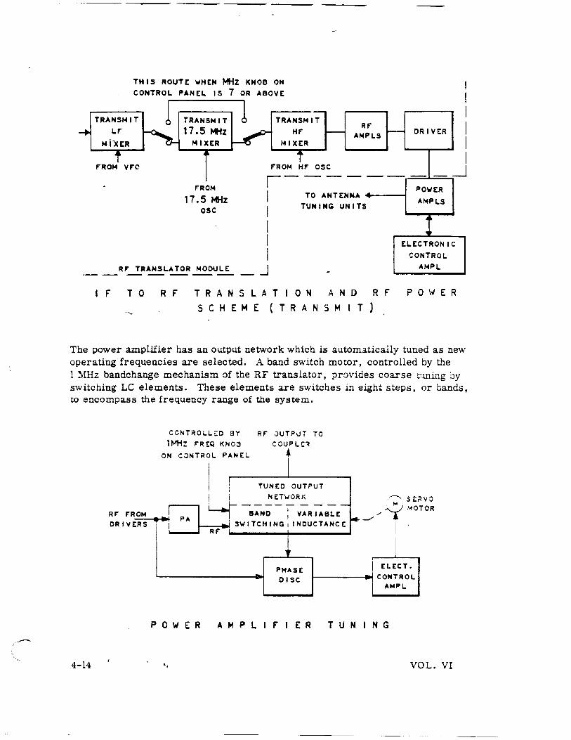
The output of the IF translator is sent to the RF translator module where it is translated into the selected operating frequency. This is accomplished by combining the IF signal with the signal of three oscillators.
The output of the RF translator is fed to the RF amplifier and then to the driver. The signal output is fed to the power amplifier module where it is amplified to 400 watts, PEP in SSB mode, or 125 watts of carrier power in the AM mode.
VOL. V:I 4-13
.·---
THIS ROUTE WHEN MHz KNOB ON CONTROL PANEL IS 7 OR ABOVE
TRANSMIT LF'
fo4 i"XER
FROM VF'C
F'ROM
17.5 MHz O!C
TRANSMIT HF'
MIXER
F'ROM HF OSC
Rf" ANPLS
,------1
I I
TO ANTENNA 4-----~ TUNING UNITS
DRIVER
I I I I I I
_ _j
POWER AMPLS
I I
ELECTRONIC
I F'
RF TRANSLATOR MODULE J
T 0 R F' T R A N S L A T I 0 N A N D R F'
S C H E M E ( T R A N S M I T )
CONTROL AMPL
PO\-IER
The power amplifier has an output network which is automatically tuned as new operating frequencies are selected. A band switch motor, controlled by the l ~1Hz bandchange mechanism of the RF translator, provides coarse t~ming by switching LC elements. These elements are switches in eight steps, or bands, to encompass the frequency range of the system.
4-14
RF' F'ROM DRIVERS
CCNT~OLL~O SY RF' ~UT?UT TO 1M-!z F'RE:Q KNOa COUF'I.!:~
ON C~NTROI. PANEL •
! I
i l TUNED OUTPUT I i N t:TWOR K
,.1 I L.! ~AN-;;-: V-;R ~8-z£-
PA .. 1 SWITCHING 1 INDUCTANCE
RF'
, PHASE DISC
.·~. St:rt ' '"'
vo TOR ,yi"O
~--- ' I .
I ELECT.
CONTROL AMP I.
P 0 W E R A M P L I F' I E R T U N I N G
.. VOL. VI
A servo loop, composed of a phase discriminator, a servo amplifier, and an A-C motor, provides fin:e tuning. The discriminator compares the phase of the RF current in the tuned network to the phase of the P A grid signal voltage and produces a D-C error signal. This error signal is applied to the Electronic Control Amplifier (ECA), converted to an A-C s_ignal, amplified, and applied to an A-C motor. The motor drives a variable inductor, fine tuning the power amplifier output network. This provides resonance in the output of the power amplifier. The output network couples the signal from the power amplifier to the antenna, providing a 1000-ohm load for the power amplifier. The antenna coupler matches the input impedance of the antenna (which varies with frequency) to the output impedance of the transmitter.
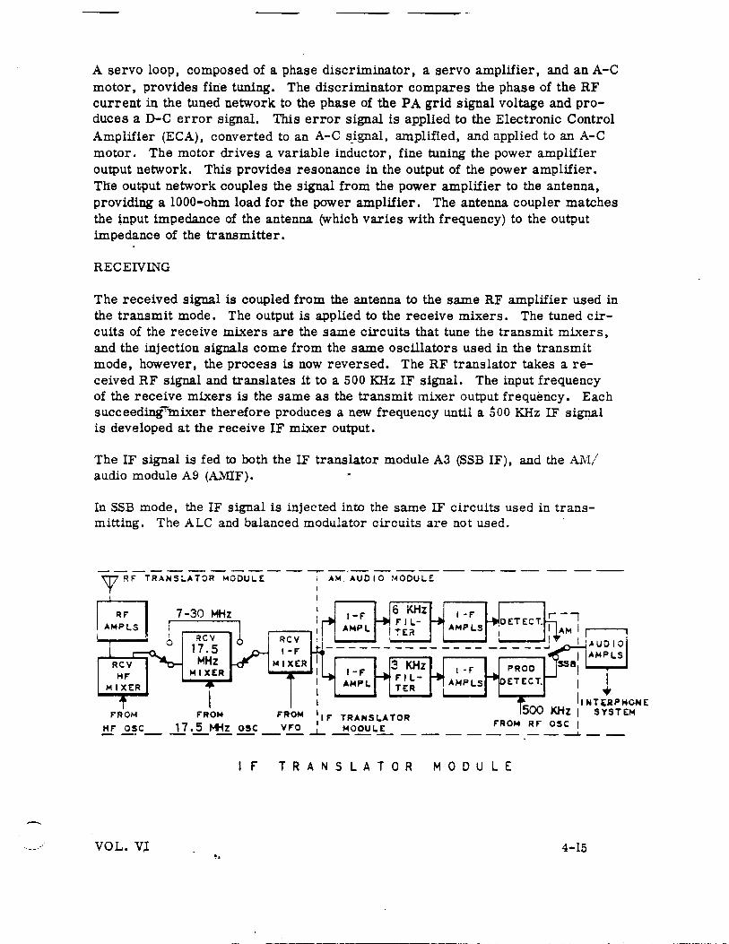
RECEIVING
The received signal is coupled from the antenna to the same RF amplifier used in the transmit mode. The output is applied to the receive mixers. The tuned circuits of the receive mixers are the same circuits that tune the transmit mixers, and the injection signals come from the same oscillators used in the transmit mode, however, the process is now reversed. The RF translator takes areceived RF signal and translates it to a 500 KHz IF signal. The input frequency of the receive mixers is the same as the transmit mixer output frequency. Each succeeding~lnixer therefore produces a new frequency until a bOO KHz IF signal is developed at the receive IF mixer output.
The IF signal is fed to both the IF translator module A3 (SSB IF), and the AM/ audio module A9 (AMIF).
In SSB mode, the IF signal is injected into the same IF circuits used in transmitting. The ALC and balanced modulator circuits are not used.
The JF output is fed to a product detector, where a 500KHz signal from the RF oscillator is mixed with the IF signal (injecting a carrier). The detector produces a difference frequency, which is the audio s1gnal. This signal is supplied to the AM/audio module where it is amplified and sent to the interphone system.
In the AM mode, the IF signal developed by the RF translator is applied to the AMIF strip in the AM/audio module. The sig:1al is then coupled to a mechanical filter. The filter has a bandpass of 6KHz to pass both upper and lower sidebands. The filter output is amplified by three IF amplifiers. The signal is then applied to a di?de detector, amplified, and coupled to the interphone system.
FREQUENCY GENERATION
Generating the selected operating frequency is accomplished by heterodyning signals from four oscillators. ·
The RF oscillator, located in the RF oscillator module, generates a constant frequency, 3 MHz signal, which is reduced to 500 KHz by regenerative dividers. This is the first signal in the frequency generating process.
- . The 17.5 MHz oscillator in the RF translator module also generates only one signal, 17. 5 MHz and is used at operating frequencies below 7 MF..z.
The two remaining oscillators, also located in the RF translator module, are variable frequency oscillators. The HF oscillator varies £rom 8. 5 througn 13 MHz in 500KHz steps, and is tuned by a band switch motor controlled from the l MHz frequency control knob on the control panel. The Variable-Freq'..l.ency Oscillator (VFO) varies from 3500 through 2501 in l KHz steps and is tuned ~y :l:e autopositioner which is supplied tuning information by the 100 KHz, ~0 ~~z, and l KHz frequency control knobs on the coz:t:-ol panel.
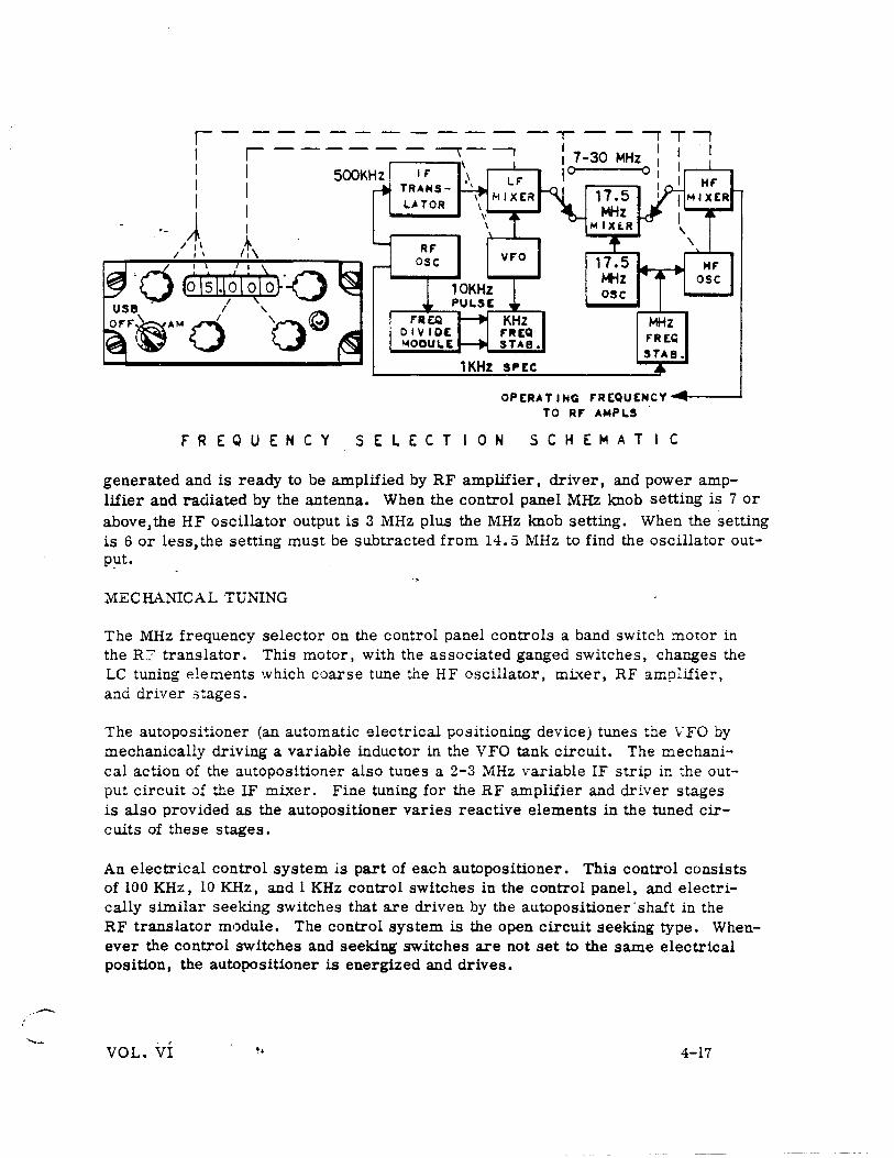
When an operatmg frequency of 5. 000 MEz is selected on ~~e cOi:.~o: ;.;a.::.·3~, :::.e following signals are generated. A 500 KHz signal from the RF osc~l5.tor module is modulated in the IF translator module. From the IF translator, th~ :nodula:ed 500 Kl!z sign.a.l 1s sent tc the RF trans~t:.:·r- r.:.odule where ~:. is oi.:·-:ed ·.vi~: ~he VFO output in the IF mixer. The VFO output in this case is 3. 5 ~.iHz (the VFO frequency = 3500 KHz - last three digits in control panel window, 3. 5 lY!Hz - . :ooi:).
The mixer output ~s therefore the difference frequency (3. 5 MHz minus 0. 5 ~1H ~ equals 3 MHz). Since the selected operating frequency is below 7 11-'lliz, the output of the low frequency mixer is applied to the 17. 5 KHz mixer. The signal is mixed with the output of the 17. 5 MHz oscillator. The difference frequency, 17. 5 MHz minus 3 MHz, equals 14.5 MHz. This signa.! is applied to t!1e HF mb:er.
In the HF mixer, the 14. 5 MHz is mixed with the output of the HF oscillator. With a control panel frequency setting of 5 MHz the output of the HF oscillator is 9. 5 MHz. Combining 9. 5 MHz with 14.5 MHz results in a 5 MHz signal, completing the frequency 1enerating process. The selected operating frequency is then
4-16 .. VOL. VI
-
osc
MHZ f'REQ STAB.
OPERATING FREQUENCY~----~ TO Rf' AMPLS
FREQUENCY SELECTION S C H E M A T I C
generated and is ready to be amplified by RF amplifier, driver, and power amplifier and radiated by the antenna. When the control panel MHz knob setting is 7 or above,the HF oscillator output is 3 MHz plus the MHz knob setting. When the setting is 6 or less, the setting must be subtracted from 14.5 MHz to find the oscillator outp~t.
MECHANICAL TUNING
The MHz frequency selector on the control panel controls a band switch motor in the R:? translator. This motor 1 with the associated ganged switches, changes the LC tuning elements which coarse tune the HF oscillator, mLxer, RF amplifier 1
and driver stages.
The autopositioner (an automatic electrical positioning device) tunes the VFO by mechanically driving a variable inductor in the VFO tank circuit. The mechanical action of the autopositioner also tunes a 2-3 MHz variable IF strip in the output circuit of the IF mixer. Fine tuning for the RF amplifier and driver stages is also provided as the autopositioner varies reactive elements in the tuned circuits of these stages.
An electrical control system is part of each autopositioner. This control consists of 100 KHz, 10 KHz, and l KHz control switches in the control panel, and electrically similar seeking switches that are driven by the autopositioner ·shaft in the RF translator module. The control system is the open circuit seeking type. Whenever the control switches and seeking switches are not set to the same electrical position, the autopositioner is energized and drives.
VOL. VI •• 4-17
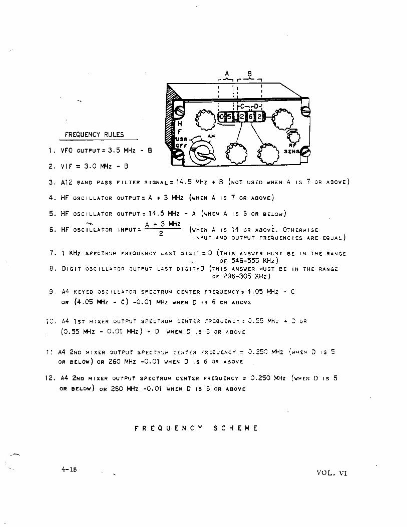
FREQUENCY RULES
1. VFO OUTPUT=3.5 MHz- 8
2. VIF = 3.0 MHz - B
3. A12 BAND PASS fiLTER SIGNAL: 14.5 MHz + 8 (NOT USED WHEN A IS 7 OR ABOVE)
4. Hf OSCILLATOR OUTPUT:. A + 3 MHz (wHEN A IS 7 OR ABOVE)
5. HF OSCILLATOR OUTPUT: 14.5 MHz -A (wHEN A IS 6 OR BELOw)
6. HF OSCILLATOR INPUT: A + 3 MHz
2 (wHEN A IS 14 OR ABOVE. O~HERWISE
INPUT AND OUTPUT fREQUENCIES ARE EQUAL)
7. 1 KH;z. SPECTR:JM fREQUENCY LAST DIGIT:. 0 (THIS ANSWER MUST BE IN THE: RA"<GE oF 546-555 KHz}
8. DIGIT OSCILLATOR OUTPUT LAST DIGIT:0 (THIS ANSWER MUST BE IN THE RANGE oF 296-305 KHz)
9. A4 KEYED OSC! LLAiCR SPECTRUM CENTER FREQUENCY: 4.05 MHz - C
OR (4,05 MHZ - C) -0.01 MHz WHEN 0 !S 6 OR ABOVE
1C. A4 1ST MiXER OUTPUT SPECTRUM :~NTE:~ rRE:CUEN:~: J.55 MH: + w OR
(0.55 *iz - 0.01 MHz) + D WHEN D ,.s 6 oR ,\aove:
. , I I A4 2ND MIXER OUTPUT SPECT~UM :ENTER F"R!:QUENC':' = J.250 MHZ ( '.1~ EN
OR BELOW) OR 260 MHz -0.01 WHEN D IS 6 OR ABOVE
12. A4 2ND MIXER OUTPUT SPECTRUM CENTER FREQUENCY = 0.250 ~Hz (WHEN
OR BELOW) OR 260 MHZ -0.01 WHEN D IS 6 OR ABOVE
FREQUENCY SCHEME
4-18 ..
D IS 5
D IS 5
VOL. VI
. . . ..... ~-
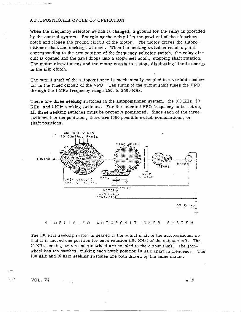
AUTOPOSITIONER CYCLE OF OPERATION
When the frequency selector switch is changed, a ground for the relay is provided by the control system. Energizing the relay l::ts the pawl out of the stopwheel notch and closes the ground cir8uii of the motor. The motor drives the autopositioner shaft and seeking switches. When the seeking switches reach a point corresponding to the new position of the frequency selector switch, the relay circuit is ?_pened and the pawl drops into a stopwheel notch, stopping shaft rotation. The motor circuit opens and the motor coasts to a stop, dissipating kinetic energy in the slip clutch.
The output shaft of the autopositioner is mechanically coupled to a variable inductor in the tuned circuit of the VFO. Ten turns of the output shaft tunes the VFO through the 1 MHz frequency range 2501 to 3500 KHz.
There are three seeking switches in the autopositioner system: the 100KHz, 10 KHz, and l KHz seeking switches. For the selected VFO frequency to be set up, all three seeking switches must be properly positioned. Since eacfi of the three switches has ten positions, there are 1000 possible switch combinations, or shaft positions.
CONTROL 'WIRES TO CONTROL PANEL
:CNTRC:L~
CCNTACTS~------------------------------~
2~.sv ::c
S I M P L I F I E D A U T 0 P 0 S ! T i 0 N E R SYSTEM
The 100 KHz seeking switch is geared to the output shaft of the autopositioner so that it is moved one position for each rotation (100 KHz) of the output shaft. The 10 KHz seeking switch anc.: stopwheel are coupled to the output shaft. The stopwheel has ten notches, making each notch position 10 KHz apart in frequency. The 100 KHz and 10 KHz seeking switches are both driven by the same motor .
VOL. V.I .. 4-19
The 1 KHz seeking switch is driven by a separate motor. This motor also drives a gear and cam arrangement which turns the output shaft to ten intermediate positions between each notch on the stopwheel. Each of the ten positions is a 1 KHz step. These ten positions, toðer with the 100 notch positions furnished by the ten rotations of stop wheel, give the required 1000 positions.
The autopositioner mechanically tunes the VFO to within 2 KHz of the selected operating frequency. In adaition, precision resistive dividers which are ganged to the seeking switches in the autopositioner submodule furnish voltage information to the KHz frequency stabilizer module. Within this module, stabilizing circuits will phase lock the VFO at the correct 1 KHz frequency point.
FREQUENCY STABILIZATION
The extremely high frequency stability required by the transceiver is obtained by using a crystal-controlled master oscillator in the RF oscillator module. This master oscillator is used to stabilize all other oscillators in the frequency generating process.
The-oscillators in the RF translator module, which are used to develop operating frequencies, are phase-locked to the master oscillator. This is accomplished by the KHz frequency stabilizer and the MHz frequency stabilizer. The KHz frequency stabilizer locks the VFO to the master oscillator. The 17.5 MHz oscillator and the HF oscillator are controlled by the MHz frequency stabilizer, again phaselocking to the master oscillator which is the frequency standard cf the system. The operating frequency is therefore as stable as the crystal osci.llat:>r, which is accurate to within 0. 8 part per million per month.
~
i.>~P-C.:>'4P
CRYST,.&L JSCiLL.lTOR ~ . "? C'2 \ .. j • ,.._.
500KHz ISOLATION
.4MPL
4-20
~ :
I "'~H· : . ..,_; ··~
! I
..,JCXt:J :JS:ILL.~TJR
+6 Q4
500KHZ ISOLATION
05
500KHz I ('11TTE:R
F"OLLOioiER
C7
I 1..0CKED 50CKHz 1 OSCILLATJR
_!.:: • ..J
Q8
1 )()KHz I 1 ClOKH z ISOLATION
AMPL Qq
.___.TO F"REQUENCY OIVIDEFI MODULE
R r 0 S C I L L A T 0 R ~ 0 0 U L E ( A 2 )
B L 0 C K D I A G R A M
.. VOL. VI
RF OSCILLATOR MODULE
The master oscillator is a 3 MHz crystal controlled oscillator. The 3 MHz output of the master oscillator is applied to a 500 KHz locked oscillator. Output of the 500 KHz locked oscillator is applied to two 500KHz isolation amplifiers and through an emitter follower to a 100 KHz locked oscillator. An output is taken from the first 500KHz amplifier for use by the megahertz frequenGy stabilizer module. Output of the second 500KHz amplifier is routed to the IF translator module. The output of the 100KHz locked oscillator is amplified and applied to the frequency divide module.
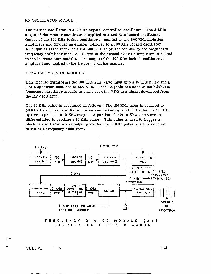
FREQUENCY DIVIDE MODULE
This module transforms the 100 KHz sine wave input into a 10 KHz pulse and a 1KHz spectrum centered at 550KHz. These signals are used in the kilohertz frequency stabilizer module to phase lock the VFO to a signal developed from the RF oscillator.
The 10 KHz pulse is developed as follows: The 100 KHz input is reduced to 50 KHz by a locked oscillator. A second locked oscillator divides the 50 KHz by five to produce a 10 KHz output. A portion of this 10 KHz sine wave is differentia:fed to produce a 10KHz pulse. This pulse is used to trigger a blocking oscillator whose output provides the 10 KHz pulse which is coupled to the KHz frequency stabilizer.
! i
100KHz 10KHz F>Rr
• I .. LOCKED 50 LOCI< EO 10 I LOC 1\ EO I BLOCKING
esc ~2 ~z osc.;. 5 KHz i osc -:- 2 -----; I osc ! I • i 10 KH:I PRF
rREQUENCY DIVIDE MODULE Al) S I M P L I r I E D B L 0 C K D I A G R A M
• I 550KHz 1KHz
SPECTRUiol
VOL.· VI .. 4-21
· ..... ~
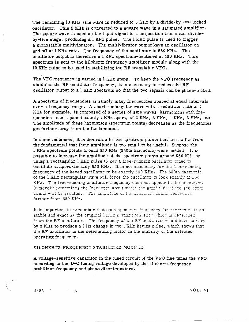
The remaining 10 KHz sine wave is reduced to 5 KHz by a divide-by-two locked oscillator. This 5 KHz is converted to a square wave in a saturated amplifier. The square wave is used as the input signal to a unijunction transistor divideby-five stage, producing a l KHz pulse. The l KHz pulse is used to trigger a mono stable multi vibrator. The multi vibrator output keys an oscillator on and off at l KHz rate. The frequency of the oscillator is 550KHz. The oscillator output i3 therefore a 1KHz spectrum-centered at 550 KHz. This sp-ectrum is sent to the kilohertz frequency stabilizer module along with the 10KHz pulse to be used in stabilizing the RF translator VFO.
The VFO freq1,:1ency is varied in 1 KHz steps. To keep the VFO frequency as stable· as the RF oscillator frequency, it is necessary to reduce the RF oscillator output to a 1 KHz spectrum so that the two signals can be phase-locked.
A spectrum of frequencies is simply many frequencies spaced at equal intervals over a frequency range. A short rectangular wave with a repetition rate of 1 KHz for example, is composed of a series of sine waves (harmonics) with frequencies, each spaced exactly 1 KHz apart, of 2 KHz, 3 KHz, 4 KHz, 5 KHz, etc. The amplitude of these harmonics (spectrum points) decreases as the frequencies get farther away from the fundamental.
In some instances, it is desirable to use spectrum points that 'are so far from the fundamental that their amplitude is too small to be useful. Suppose the 1 KHz spectrum points around 550 KHz (550th harmonic) were needed. It is possible to increase the amplitude of the spectrum points around 550 KHz by using a rectangular 1 KHz pulse to key a f.:-ee-rur.ning oscillator tuned :o oscillate at approximately 550 KHz. It is not :1ecessary ror the f.:-ee-n:.nning frequency of the keyed oscillator to be exactly 550 KHz. The 550th !la.rmonic of the 1 KHz rectangular ·.vave will :orce the oscillatcr to :ock exacti.y at .350 KHz. The free-running oscillator frequency cioes not apper in the srcectru.::n. It merely determines tl:e .:r"ec;,uenc~· a0out wl::~:-. ::1e a.:r:~U~:..de r;,: ~ie 3?'2.: :r',.;,;:-: points \\·il: ~e ~~eatest. The a~1pli~:1de oft~~~, 3~;~:~:::~~-:: ~o:~:2 :2c·~·~:..~·.:3
farther from 550 KHz.
It is important to re~embe!' that each spec~ru:r:: ~re<~:..:ency (or :~ar~:on!.c; is as stable ana exact as t~e orig:::.::..l l !~I-l.z 1: 'Ylr.:; f_-.~ '_e::-::· ,::i:1c:: :2 c:e~e, :-;::eel from the RF oscillator. The frequency of t.be R.? csc~ ... ~au:=- ·,n;uld have to vary by 3KHz to produce a l Hz change in the l KHz keying pulse, '.~t·hich show3 that the RF oscillator is the determining factCJr in the stabil.ity of the selected operating frequency.
Y..ILOHERTZ FREQUENCY STABILIZER MODC'LE
A voltage-sensitive capacitor in the tuned circuit of the VFO fine tunes the VFO according to the D-C tuning voltage develop~d by the kilohertz frequency stabilizer frequency and phase discriminators.
4-22 ., VOL. VI
The inputs to the phase discriminator are two 250 KHz IF signals. One is the VFO frequency that has been heterodyned to 250KHz (signal IF). The other is the RF oscillator frequency that has been heterodyned to 250KHz (reference IF).
546-555 KHz 250 KHz 250 KHz
VF'O INPUT 2501-3500 KHz
F'IRST MIXER
3050-4050 KHz-' KEYED
~ iO KHz PULSE. F'RO F'RtQ -7MOD
10 KHz KEYER ~ osc
1 KHz DC CONT F'ROM AUTOPOSIT
... ULE . j o---10 KHz AND 100
KHz 0C C ONT F'Ro.4 AU."C_Q_POS IT I ON ER
lONER
1
0 1 KHz SPECTRUM~ F'Ro.4 F'R EQ . .
MODULE
SECOND I 250 KHz I SIGNAL ....,. F'l L.TER ~ -MIXER IF' AMPL.S
8 KHz BW
'·-296-305 KHz DIGIT ,
osc F'R [Q
1'4" PHASE DISC ~ DIS:
-296-305 KHz • I
, 250 KHz 250 KHz
Rtr I 250 KHz ! Rtf' 1; ...... F'ILTER ..._. r-
MIXER O.SKHz BW AMPl.S
DC CONTROL TO VF'O
K H z F'REQUENCY STABILIZER MODULE { A 4 )
S I M P L F' I E D 8 L 0 C K D I A G R A M -
The phase discriminator output is a D-C error signal. This error signal "pulls" the VFO frequency, by tuning the voltage sensitive tuning capacitors in the VFO tuned circuits, until the two signals are phase locked.
To develop the 250 KHz signal, the VFO 3ignal is mLxed with a spectru.."ll of frequencies 10 KHz apart which is centered approximately 550 KHz higier in frequency than the VFO. As the VFO ~s variec! from 3500 ~o 250~ KHz, the center of the 10KHz spectrum moves frcm 4050 w 3050 KHz. This 1·1 :':Ez spectrum is derived from the 10KHz pulse, :rc;r::. t.':.~ £:-ec;uer:cy div::<e .. :1:.c.:_e, from which a multivibratOl' procl:.1ces a reci:a:1gda.:- pulse to key ac o.:;:i.i.::::..:;:;r, The free-running frequency of the keyed oscillator is approximately 550 KHz higher than the VFO. The keyed oscillator is tuned by a D-C voltage applied to a voltage-sensitive capac ito:-. The tunm:~; ·; o: :ag8 lS \ a.:-ieC: :~y t!: e ::a:.:::>positioner as the 10 KHz and 10 KHz frequency comrcl knobs on the control p:mel are varied. A regulated D-C voltage is applied to a precision resistance bridge which serves as the .source of tuning voltage for the keyed oscillatcr. Rotary switches, driven by the autopositioner, select different voltage points on the bridge as the selected operating freq'-lency is varied. 100 D-C voltages are possible to tune the keyed oscillator to any one of 100 possible operating frequencies between 3. 05 anc! 4. 05 MHz. The operating frequency of the keyed oscillator can be determined by subtracting the 100 KHz and 10 KHz knob digits on the control panel from 4. 05 MHz. (KO = 4. 05 MHz - 0. XXO).
VOL., VI 4-23 .,
. --
In the example previously used, when an operating frequency of 5, 000 MHz is selected on the control panel, the VFO frequency is 3500KHz and the keyed oscillator spectrum is centered at 4050 KHz.
Mixing the VFO output and the keyed oscillator signals produces a spectrum output from the first mixer containing frequencies spaced 10 KHz apart and centered around 550 KHz. This signal is combined in a second mixer with a . -signal from a free-running digit oscillator. The digit oscillator output is a single frequency which is varied by the 1 KHz frequency control knob on the control panel.
The digit oscillator is also tuned by a voltage-sensitive capacitor. The tuning voltage is derived from another precision resistive divider in the autopositioner. The oscillator generates ten signals which are 1 KHz apart, from 296 to 305 KHz. The last digit on the control panel always matches the last digit of digit oscillator frequency within lts range. With 5. 000 MHz selected on the control panel, the digit oscillator output fr~quency is 300 KHz. The 550 KHz spectrum from the first mixer is combined with this signal in the second mixer. The mixer output is another spectrum of frequencies spaced 10 KHz apart but centered around 250 KHz. This signal is passed through a mechanical filter. The filter has a band pass of 8 KHz to insure that the 250 KHz spectrum point will be passed, and spectrum points 10 KHz away will not pass since the filter bandwidth extends only 4KHz on each side of 250KHz.
Vari:J.tions of the signal IF frequency result frc:n VFO freqt:ency changes. After amplification by II-' amplifiers, the 250KHz signal is supplied to the frequency discriminator. The freq;..:ency discriminator output pulls the VFO signa~. bringing the signa: ::: freq:1e::1cy closer to 250 KHz and within the capture ra:J.ge oi the ?b.ase discric:ll.nator. 7hc ~,-F() ~s pu::ed to ·.v:.min :: 200 Hz o: the
Si:ec:::-ur.:: cente_·ect .1: 550 K..:..r.: frc.m the freque::-.cy divide ::::;::odL:le is mixed with the digit oscillator output of 300 K..liz i.rr t.'1e reference mLxer. The mixer output :3 :. t :\:E:: 3~e0::-·· .. :-::: ce:.~er?d ar~u=-~ 25C :~~-!::. T>J..s si~al is ~a.:;sed through a 8~/sta: fi~~e:'" ,,\·hlCG i:As z. QanC~v~~:.-:,. :.:~ ..., .. ·: ~.::...:-r.:. ·:-::-.. z l:1ixer ou~tJu: :·req~ency of 250 KHz is passed, but spectrtl.IlC. poi::J.ts l KHz away do not pass since the filter bandwidtl1 e:\.""te::J.ds only 400Hz on eit.l-:le:r side of 250KHz.
The digit oscillator does require stabilization. Any digit oscillator error is cancelled since the oscillator output is common to both the reference IF and t!:J.e sig:1al I.F. How3ver, the digit oscillator :nust not vary more t."lan:: 200 Hertz from its proper frequency for the signal IF to function properly. If these limits are exceeded, the frequency discriminator will see the error and correct the VFO erroneously .
VOL. VI
--
There are now two 250 KHz IF signals to be applied to the phase discriminator. These signals are the reference IF developed from the RF oscillator signal and the signal IF developed from the VFO signal. The 250KHz signal IF is first applied to the frequency discriminator. If a large frequency error exists, the D-C error signal developed by the frequency discriminator tunes the VFO, bringing the signal IF frequency within range of the phase discriminator. The phase discriminator control voltage overrides the frequency discriminator control·voltage to phase-lock the VFO to the RF oscillator signal.
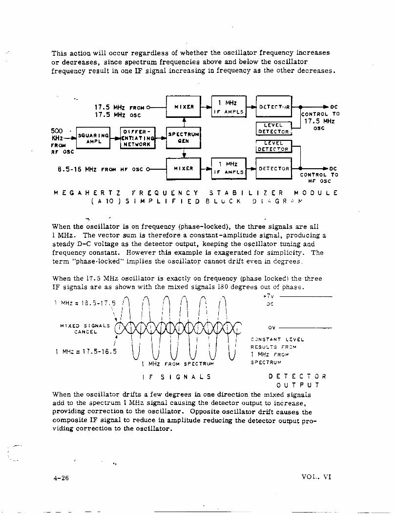
The_HF oscillator and the 17.5 MHz oscillator also have voltage-sensitive capacitors in their tuned circuits. The tuning voltage for the capacitors comes from a diode detector. The signal into -the diode detector is a combination of three 1 MHz IF signals obtained by mixing the oscillator outputs with a 500KHz spectrum. This spectrum is derived from a 500KHz signal from the RF oscillator module. The amplitude of the sum of these three 1 MHz signals is proportional to the phase error of the oscillator. Since each oscillator has similar control circuit, stabilization of only the 17. 5 MHz oscillator is described here.
DEVELOPING THE 500KHz SPECTRUM. A square wave is developed from the 500 KHz signal from the RF oscillator. A differentiating network produces a pulse froni~the square wave. This pulse is used to trigger a spectrum generator. A ringing circuit in the output of the spectrum generator produces a 500 MHz spectrum centered at approximately 7 MHz and extending from 500KHz to 25 MHz and beyond.
When this spectrum is mixed with the 17.5 MHz oscillator output, the mixer output will contain a l MHz signal derived from the 1 !\11Hz spectrum frequency (2nd harmonic) of the input spectrum. Since the spectrum extends from 0. 5 to 25 !\11Hz, a second l MHz IF signal is obtained by mixing the oscillator frequency (17. 5 :\1Hz) with the 16.5 MHz spectrum frequency. The th:.rd l :\Uiz IF results from mixing the oscillator frequer.cy (:7. 5 :\1Hz) wit::. the 18.5 ::\lliz spectrum frequency. If the oscillator frequency varies from 17. 5 :\1Hz the frequency of the second and t.~ird IF signals change by the same amount.
If, for example, the oscillator frequency increases by 200 Hz, mb~in& the oscillator output with the 16.5 MHz spectrum point will produce an IF signal of l. 0002 MHz. M1xing the oscillator output with the 18. 5 MHz spectrum point results in an IF signal of o. 9998 l'rlHz.
Combining the first IF signal (1 MHz) with the two developed by·mixing will result in a varying amplitude signal which is somewhat similar to amplitude modulation. The output of the diode detector will therefore vary, causing the frequency of the 17. 5 MHz oscillator to vary because the detector output tunes the voltage sensitive capacitor in the oscillator tuned circuit. The oscillator frequency will tend to swing back and forth above and below its lock-in frequency.
VOL. VI .. 4-25
---~-·--------·----
This action will occur regardless of whether the oscillator frequency increases or decreases, since spectrum frequencies above and below the oscillator frequency result in one IF signal increasing in frequency as the other decreases.
·- 1 17.5 MHz MIXER _., MHz ..... DETEr.T<IR ..
F'ROM
17.5 MHz osc IF' AMPLS CONTROL
DC TO
Hz
__.. 500 KHz F'ROfo4 RF'
SQUARING 0 IF' F'ER-
r+ EMTIATINQ AMPL
NETWORK
osc
8 .5-16 MHz F'ROfo4 HF' OSC
f SPECTRU._. _.
QEH
t MIXER
1 to~ Hz ~ IF' AMPLS
-+
LEVEL ~ DETECTOR'·
- LEVEL r-IDETEC'TOR
DETECTOR
17.5 M osc
CONTROL DC TO
HF' OSC
MEGAHERTZ f"REQUENCY STABILIZER MODULE ( A 10 ) S I M P L I f" I E 0 8 L u C K D I ;:; G R " ~
When the oscillator is on frequency (phase-locked), the three signals are all l MHz. The vector sum is therefore a constant-amplitude signal, producing a steady D-C voltage as the detector output, keeping the oscillator tuning and frequency constant. However this example is exagerated for simplicity. The term "phase-locked" implies the oscillator cannot drift even in degrees.
When the 17.5 :\1Hz oscillator is exactly on frequency (phase locked} the three IF signals are as shown with the mLxed signals 180 degrees out of phase.
MHZ: 13.5-17.5 n (\ /I. t7v ,, I . I ac:
\ I \ I : i I
' I i I I .., -
M I X£0 SIGNALS if' ov CANCEL
4 C~NSTANT LEVEL
J i R£SU~TS FR:JM MH;:: 17.5-16.5 u 1 MHz FRO I-A
MHZ F'ROM SPECTRU"' SPE:CTRU~>'
f" s I G N A L S D E T E C T 0 R 0 u T P U T
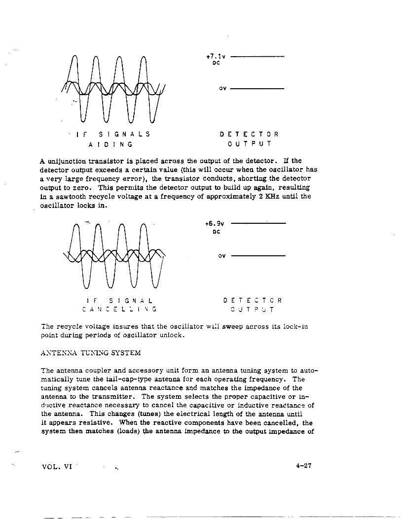
When the oscillator drifts a few degrees in one direction the mixed signals add to the spectrum l MHz signal causing the detector output to increase, providing correction to the oscillator. Opposite oscillator drift causes the composite IF signal to reduce in amplitude reducing the detector output providing correction to the oscillator •
.. 4-26 VOL. VI
·IF SIGNALS
A I D I N G
t7 .1v DC
ov-------
DETECTOR 0 U T P U T
A unijunction transistor is placed across the output of the detector. If the detector output exceeds a certain value (this will occur when the oscillator has a very large frequency error), the transistor conducts, shorting the detector output to zero. This permits the detector output to build up again, resulting in a sawtooth recycle voltage at a frequency of approximately 2 KHz until the oscillator locks in.
I F S I G N A L C A N C E L ~ I ~ G
+6.9v DC
ov
DETECTCR 0 U T P J T
The recycle voltage insures that the oscillator will sweep across its lock-in point during periods of oscillator unlock.
AXTEX::\A TlJNTNG SYSTEM
The antenna coupler and accessory unit form an antenna tuning system to automatically tune the tail-cap-type antenna for each operating frequency. The tuning system cancels antenna reactance and matches the impedance of the antenna to the transmitter. The system selects the proper capacitive or ind•Ictive reactance necessary to cancel the capacitive or inductive reactance of the antenna. This changes (tunes) the electrical length of the antenna until it appears resistive. When the reactive components have been cancelled, the system then matches (loads) the antenna impedance to the output impedance of
VOL. VI .. 4-27
r I I I I I I
I
~--
TO No.l~~~~------< • .RCV" CKTS I
-':\O::Y! N~j
: ~ E LA 'f i I I
I
I
'--------1.---c----:.B IT 0 p !'T
'~~--' I ~ E: LA':' . I rvTLK ·
, __
LI~HTNINQ
A,.,.ESTO,.
__..J
----, I
------,.1-~ ... TO No.2 RCV,. CKTS
I
T,.ANSI "ELAYI No.2
:~ I
:--" ' -<
.)
.--1 : ::; E: 'f I N G
I <.A: I~~
I ~~TI C~· -.,-! .. -----1 'L.l.A,Y (_j
I
MIKE SWITCH I•(CLOSED)
Hf-102 NTERLOCK C I R C U I T S
.. 4-23 VOL. VI
the transmitter. When system No. 1 is keyed, a ground is applied to the coil of a keying relay in the coupler accessory unit No. 1. The .~elay coil is supplied 28-volt, D-C power through contacts of the deenergized interlock relay in coupler accessory unit No. 2. Contacts of the keying relay supply 28-volt, D-C power to transmit relay No. 1 in the lightning arrestor unit. The transmit relay contacts connect the transmitter RF signal from system No. 1 to the antenna •. _ The relay also completes the coil circuit of the interlock relay in the antenna accessory unit No. 1. Contacts of the interlock re~y open the key line of system No. 2 to prevent simultaneous keying of the systems.
The interlock relay contacts also open the coil circuits of the No. 1 and No. 2 receive relays in the lightning arrestor relay unit. The receive relays disconnect the antenna from the receivers and ground both receiver inputs. This prevents the high-level transmitter RF energy from entering the receiver circuits. When the key line ground is removed, the relays of accessory unit No. 1 deenergize and power is applied to the receive relays in the lightning arrestor relay unit. The relays energize to remove the ground from the receivers and connect the antenna. This permits simultaneous use of the receivers. The interlock circuits for system No. 2 operate in a similar manner, using the relays of accessory unit No. 2.