117
1 RECONFIGURATION IN WDM NETWORK WOOCHANG HWANG TAEKKYEUN LEE
| Date post: | 19-Dec-2015 |
| Category: |
Documents |
| View: | 215 times |
| Download: | 0 times |

1
RECONFIGURATION IN WDM NETWORK
WOOCHANG HWANGTAEKKYEUN LEE
2
Overview
I. ReconfigurationII. WDM NetworkIII. Virtual TopologyIV. Schemes V. Decision
3
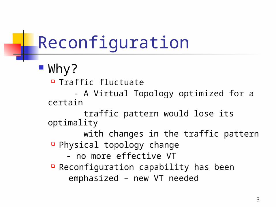
Reconfiguration Why?
Traffic fluctuate - A Virtual Topology optimized for a certain traffic pattern would lose its optimality with changes in the traffic pattern
Physical topology change - no more effective VT Reconfiguration capability has been
emphasized – new VT needed
4
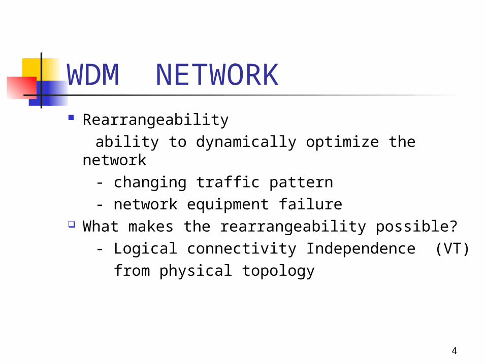
WDM NETWORK Rearrangeability ability to dynamically optimize the network - changing traffic pattern - network equipment failure What makes the rearrangeability possible? - Logical connectivity Independence (VT) from physical topology

5
WDM NETWORK Lightpath set up by configuring the optical switches and
tranceivers - provide single-hop communication channels between the end nodes - eliminate the electronic processing at intermediate nodes Virtual Topology A set of static light paths established to all- optical connectivity between nodes for a given traffic demand

6
Reconfiguration Step Overview
Get information about trafiic /PT Get optimal VT to adapt to new traffic
pattern Should be the VT that minimize the disruption
in the network (closeness to current VT) Decision to trigger reconfiguration or not
to Transition from old VT to new VT
7
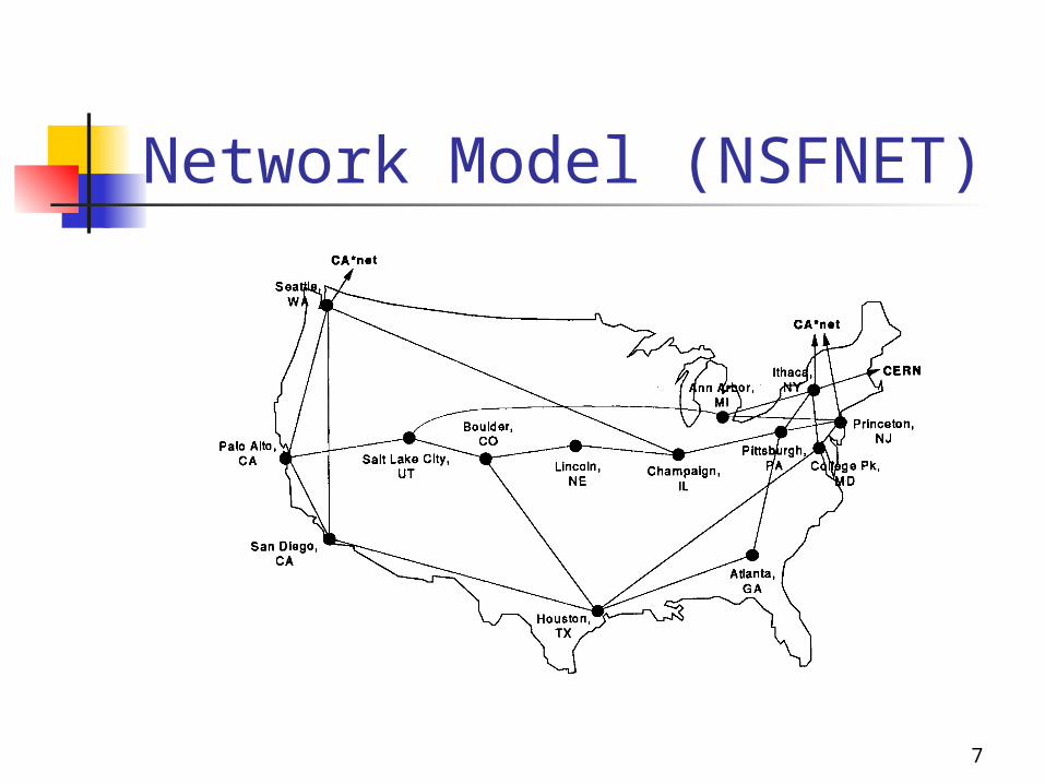
Network Model (NSFNET)

8
Scheme 1 – Problem specPHYSICAL TOPOLOGY:
Gp = ( V,Ep) ; V = Set of network nodes
Ep= Set of links connecting the nodes
Dp(i) = Physical Degree of node i
Wavelength channels carried by each fiber = W
N*N traffic matrix, where N is the number of network nodes

9
Scheme 1 –problem specVIRTUAL TOPOLOGY:
A virtual topology Gv = (V,Ev)
Two light paths that share a common link must use different wavelengths
Sizes and configurations of the WRSs
10
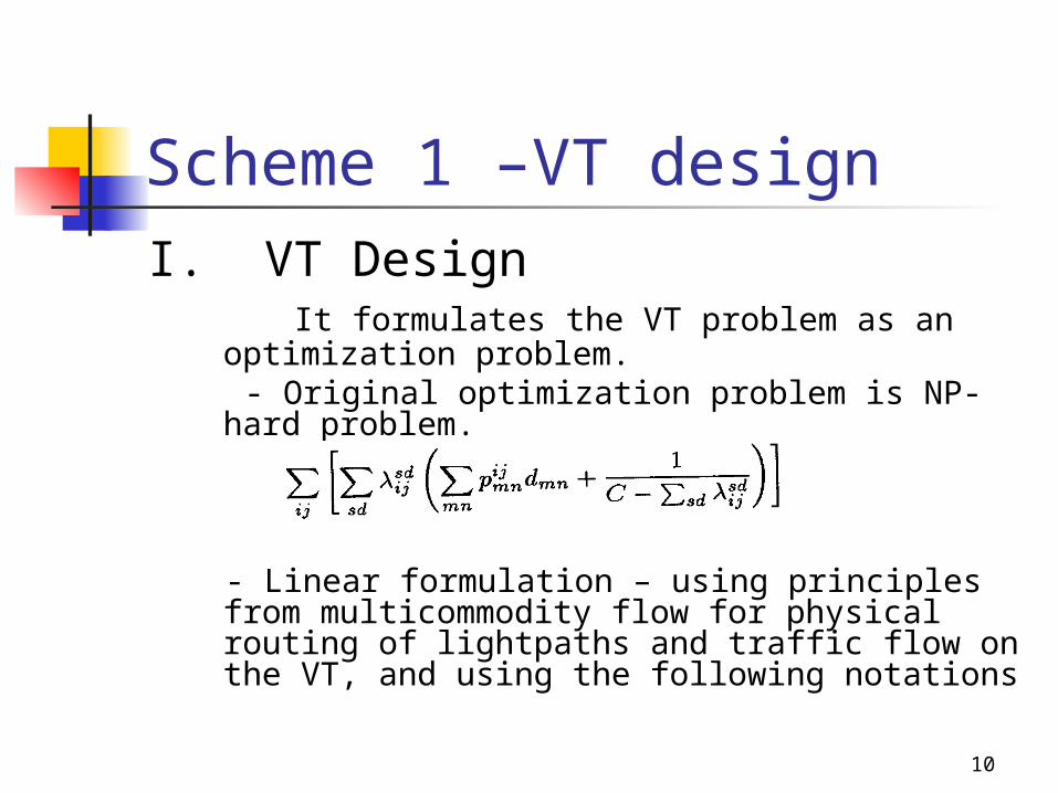
Scheme 1 –VT designI. VT Design It formulates the VT problem as an
optimization problem. - Original optimization problem is NP- hard
problem.
- Linear formulation – using principles from multicommodity flow for physical routing of lightpaths and traffic flow on the VT, and using the following notations
11
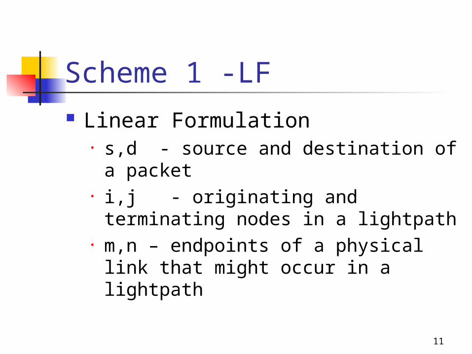
Scheme 1 -LF Linear Formulation
• s,d - source and destination of a packet
• i,j - originating and terminating nodes in a lightpath
• m,n – endpoints of a physical link that might occur in a lightpath

12
Scheme 1 -LF1. Given
• N = Number of node in the network• W= Max number of wavelengths per fiber• Pmn = number of fibers interconnecting nodes m
and n. Pmn=0 for nodes which are not physically adjacent.
denotes the total number of fiber links in the network.
• dmn = fiber length distance between m and n ,expressed as a propagation delay• D = shortest path delay matrix Dij denotes the delay(sum of propagation delay only) over the shortest path between i and j

13
Scheme 1 -LF• α = Lightpath length bound, 1<= α < bounds the delay over a lightpath betwee two nodes I and j, with respect to the shortest path delay Dij between them. max permissible propagation delay α * Dij• Ti = number of transmitters at node I Ri = number of receivers at node I sd =traffic matrix, denotes the average rate of traffic flow from node s to d (in
packets/sec)

14
Scheme 1 -LF• C = capacity of each channel =max loading per channel, 0< <1 restricts the queueing delay on a lightpath from getting unbounded by avoiding excessive link congestion -negligibly small compared to propagation delay for a large network , so we do not incorporate queuing
delays explicitly

15
Scheme 1 -LF2. Variables• Vij= Virtual topology ,number of lightpaths
from node i and j in the VT• = Traffic routing, the traffic flowing from
node s to node d and employing Vij as an intermediate virtual link.
• = physical topology route, number of lightpaths between nodes i and j being routed through fiber link mn.
16
Scheme 1 -LF
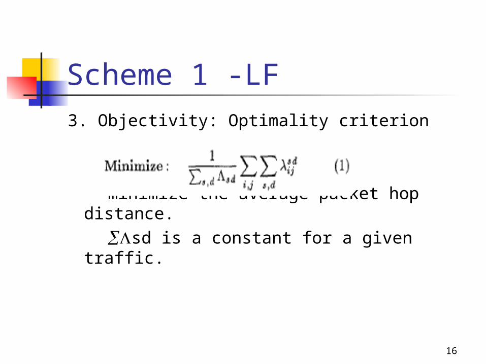
3. Objectivity: Optimality criterion
minimize the average packet hop distance.
sd is a constant for a given traffic.
17
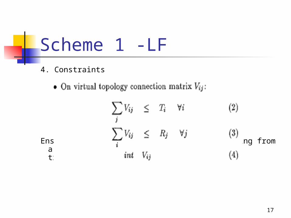
Scheme 1 -LF4. Constraints
Ensures that the number of lightpaths emerging from a node is constrained by the number of transmitters and receivers

18
Scheme 1 -LF
(5)=flow traffic is conserved at intermediate nodes(5)-(7) are multi commodity flow equations governing the routing
lightpaths from source to destination
19
Scheme 1 -LF
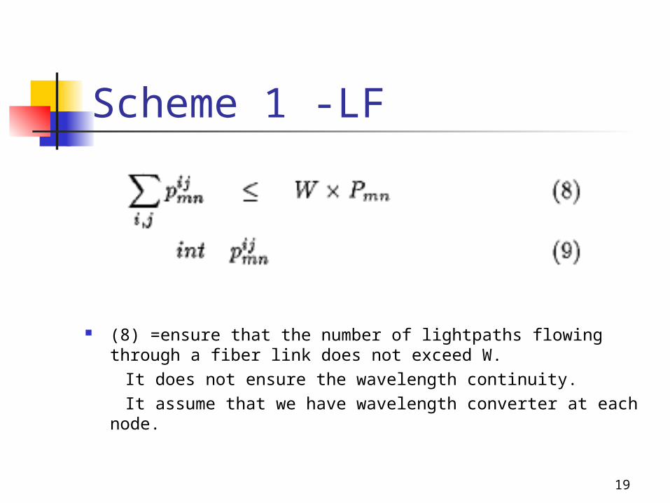
(8) =ensure that the number of lightpaths flowing through a fiber link does not exceed W.
It does not ensure the wavelength continuity. It assume that we have wavelength converter at each node.
20
Scheme 1 -LF
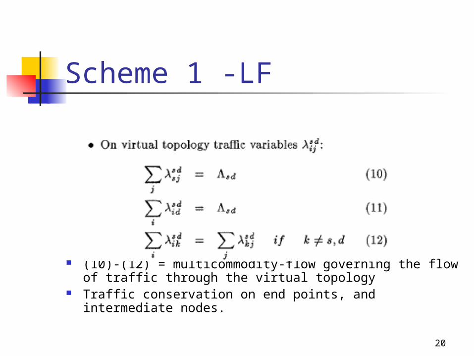
(10)-(12) = multicommodity-flow governing the flow of traffic through the virtual topology
Traffic conservation on end points, and intermediate nodes.

21
Scheme 1 -LF
(13)= ensure that traffic can only flow through an existing lightpath
(14)= specify the capacity constraint in the formulation

22
Scheme 1 -LF

23
Scheme 1 -LF (15)-(16)= May be incorporated to ensure
bounded packet delays and to reduce the solution space of the problem
(16) restricts the enumerated variables to be only among those in K alternate shortest paths from I to j, where K >= 1.
- prevent a lightpath with an unnecessarily long route instead of a much shorter route.

24
Scheme 1 -LF5. Simplifying assumptions • The number of variables and equation in the formulation are reduced - To make the problem more tractable, It reduce the number of constraints by pruning the search space. - tracking a limited number of alternate shortest paths, denoted K, between source and destination, such that the selected routes are within a constant factor ( >=1) of the shortest path. - all values of and are not enumerated - The amount of pruning required is a function of the size of the
problem that can be solved in reason able time by the chosen LP solver.

25
Scheme 1 -LF• Wavelength-continuity constraints for a lightpath are
intentionally ignored
• Queueing delays are also intentionally ignored, since propagation delay dominates
• The current formulation allows bifurcated routing of packet traffic.
-Non-bifurcated routing significantly increased the running time of the optimization

26
Scheme 1 –heuristic approach
6. Heuristic Approaches - become important when the
problem formulation becomes large due to increase in the size of the network, and becomes difficult to solve by LP methods due to constraints.

27
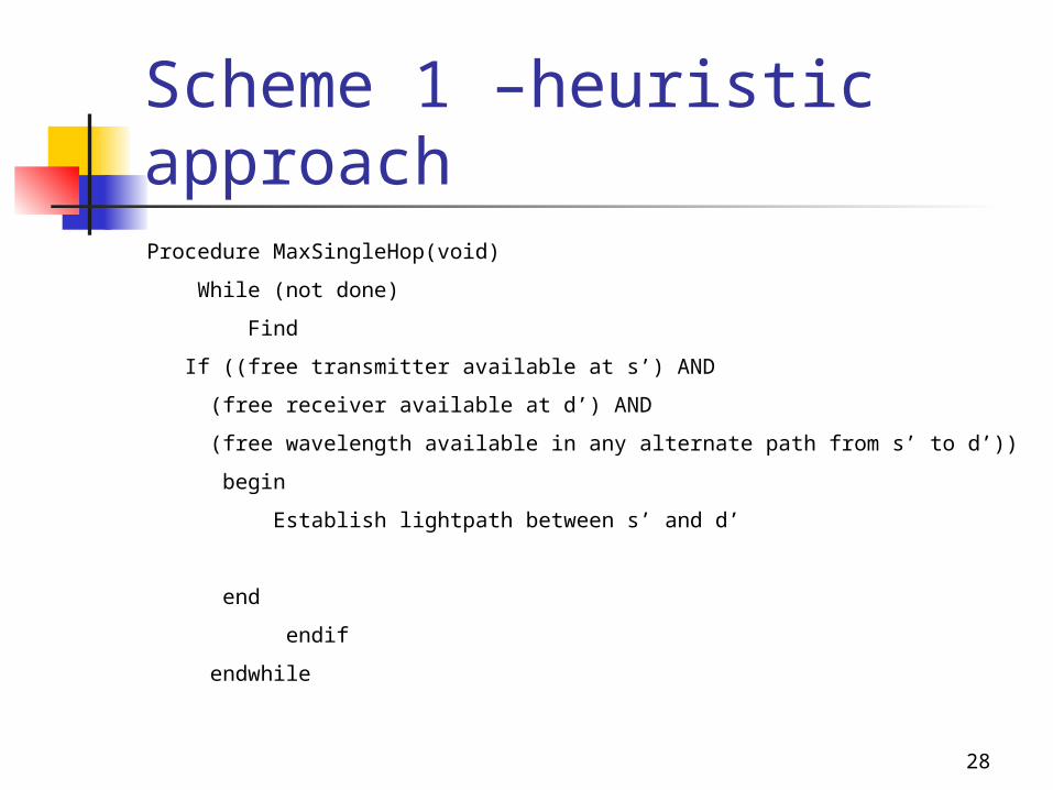
Scheme 1– Heuristic approach Maximizing single-hop traffic
Attempts to establish lightpaths between source-destination pairs with the highest sd values, subject to constraints on the number of transceivers at the two end nodes, and the availability of a wavelength in some path connecting the two end nodes.
28
Scheme 1 –heuristic approachProcedure MaxSingleHop(void)
While (not done)
Find
If ((free transmitter available at s’) AND
(free receiver available at d’) AND
(free wavelength available in any alternate path from s’ to d’))
begin
Establish lightpath between s’ and d’
end
endif
endwhile
29
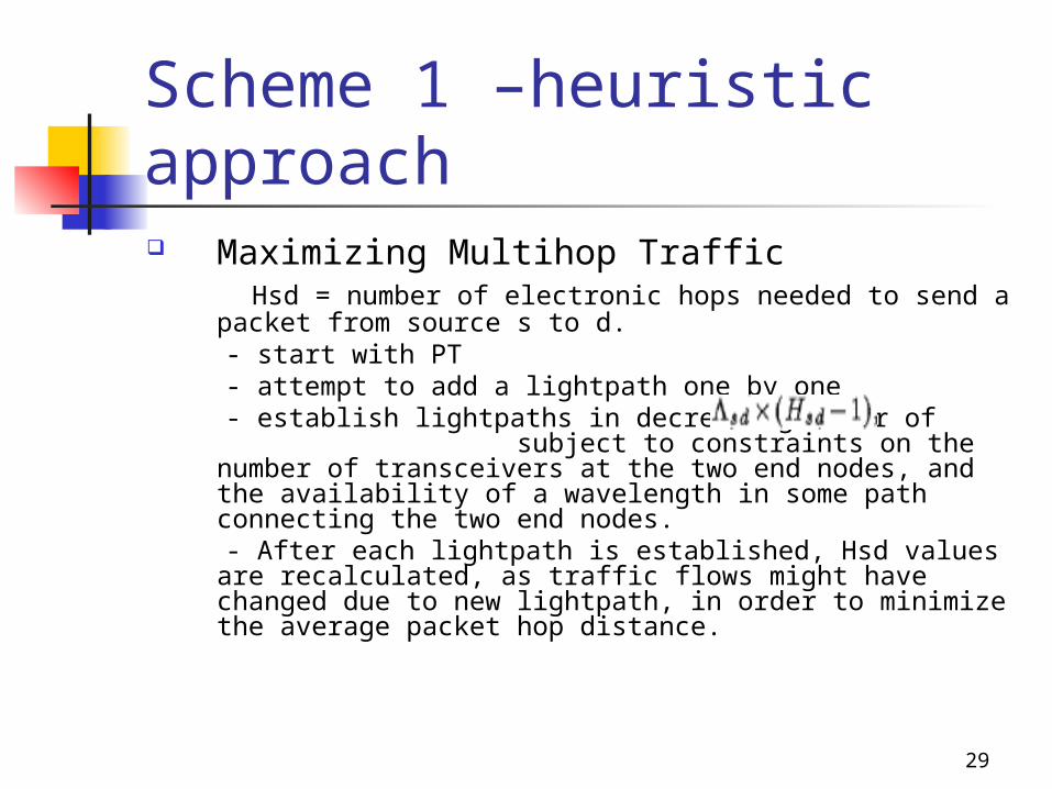
Scheme 1 –heuristic approach Maximizing Multihop Traffic Hsd = number of electronic hops needed to send a packet
from source s to d. - start with PT - attempt to add a lightpath one by one - establish lightpaths in decreasing order of
subject to constraints on the number of transceivers at the two end nodes, and the availability of a wavelength in some path connecting the two end nodes.
- After each lightpath is established, Hsd values are recalculated, as traffic flows might have changed due to new lightpath, in order to minimize the average packet hop distance.

30
Scheme 1 –heuristic approachProcedure MaxMultiHop(void) Initial Virtual Topology = Physical Topology while (not done) compute Hsd for all s,d find new s’d’(Hs’d’-1) = Max (sd(Hsd-1) ) if ((free transmitter available at s’) AND (free receiver available at d’) AND (free wavelength available in any alternate path from s’ to
d’)) begin Establish lightpath between s’ and d’ end endif endwhile

31
Scheme 1 -reconfiguration
II. Reconfiguration -prefer for the new VT to largely similar to the current VT(closeness) - minimize the changes in the
number of WRS configurations needed to adapt from existing VT to new VT.

32
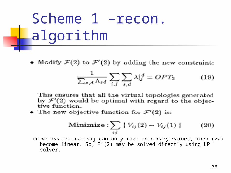
Scheme 1 -Recon. algorithm Algorithm
33
Scheme 1 –recon. algorithm
If we assume that Vij can only take on binary values, then (20) become linear. So, F’(2) may be solved directly using LP solver.
34
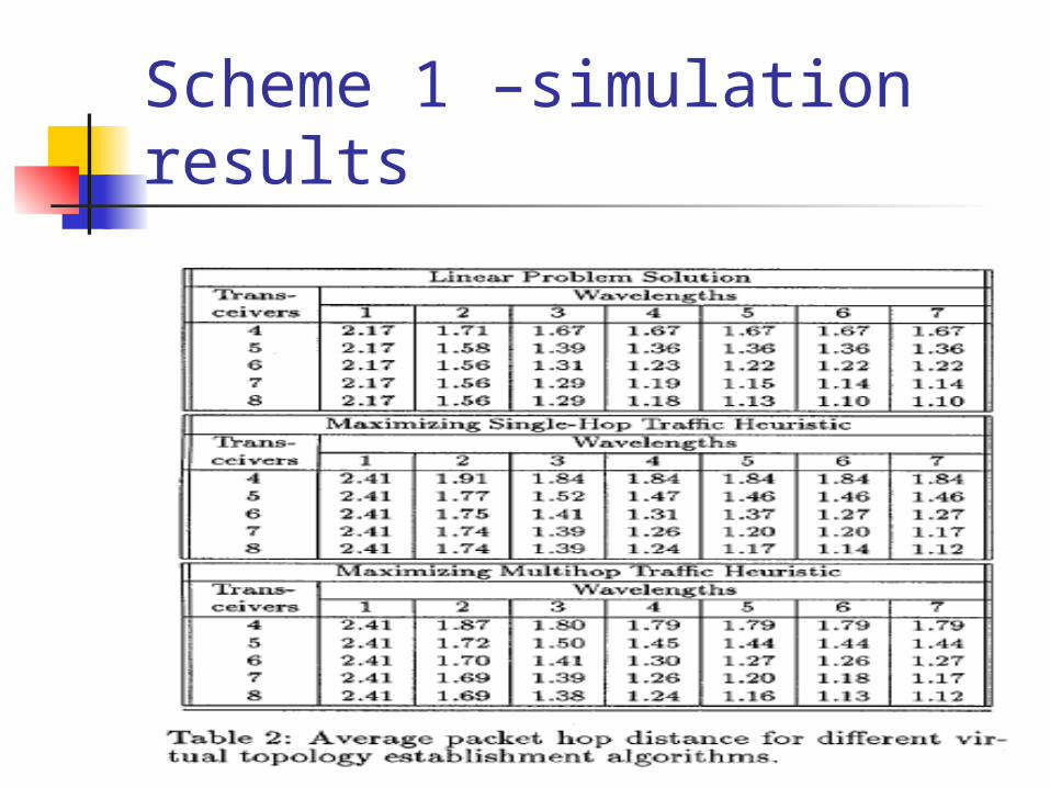
Scheme 1 –simulation results

35
Scheme 1 –simulation results
36
Scheme 2 – problem spec Almost same as the scheme 1
except some parameters and objective function
Also reconfiguration algorithm is little bit different.
37
Scheme 2 -LF
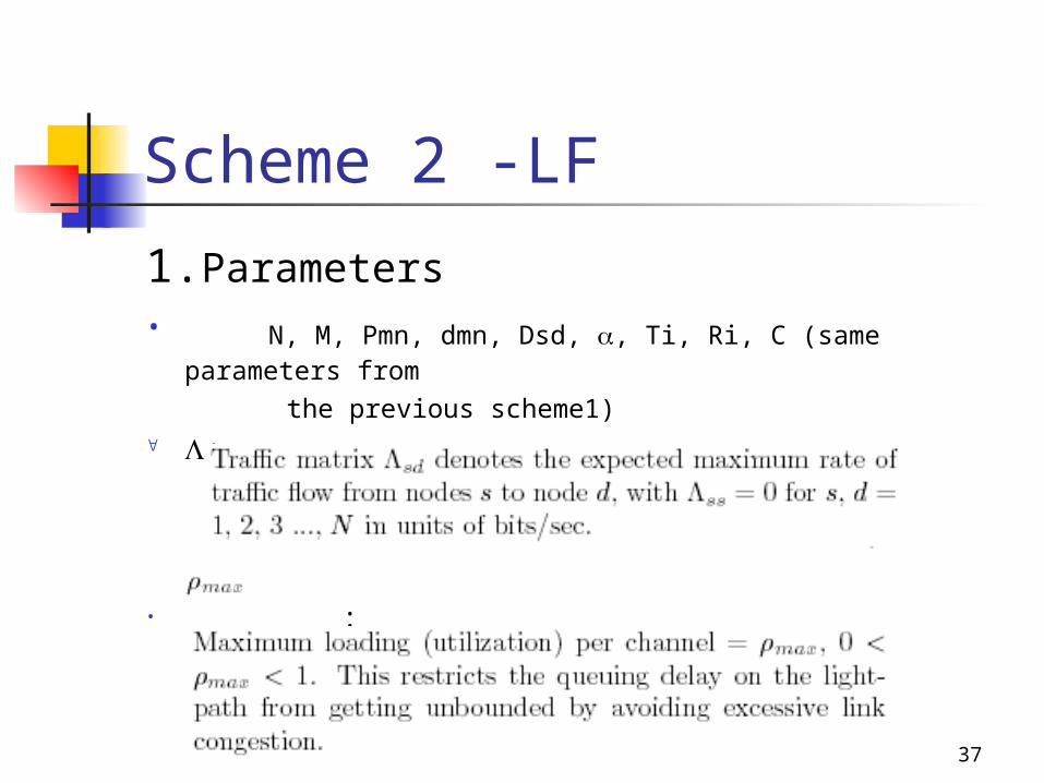
1.Parameters• N, M, Pmn, dmn, Dsd, , Ti, Ri, C (same parameters from
the previous scheme1) :
• :

38
Scheme 2 -LF 2. Variables
denotes the number of lightpaths between nodes I and
j being routed through the fiber links between m and n.
39
Scheme 2 -LF
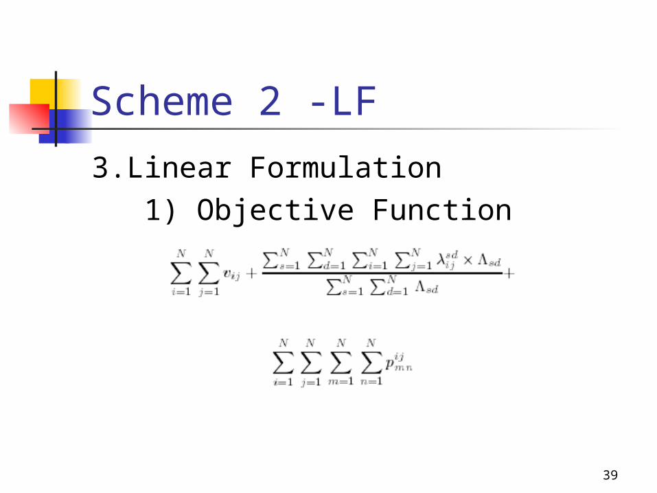
3.Linear Formulation 1) Objective Function

40
Scheme 2 -LF First term: Minimize the total
number of lightapths set up in the network.
Second term: minimize the average number of hops in the network encountered by a packet. (previous scheme’s objective)
Third term: minimize the number of physical links used.
41
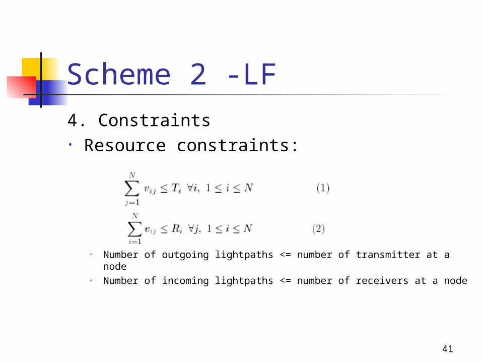
Scheme 2 -LF
4. Constraints• Resource constraints:
• Number of outgoing lightpaths <= number of transmitter at a node
• Number of incoming lightpaths <= number of receivers at a node
42
Scheme 2 -LF

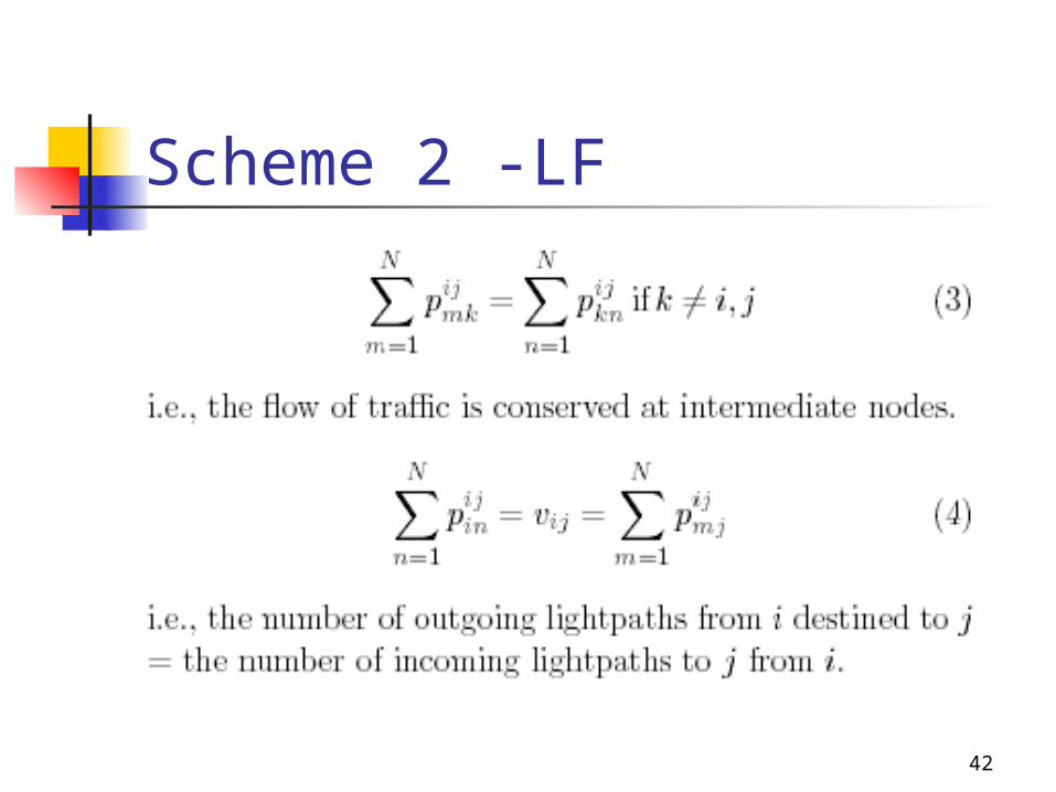
43
Scheme 2 -LF
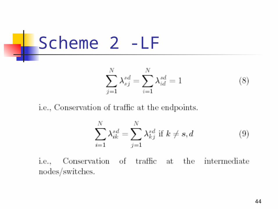
44
Scheme 2 -LF

45
Scheme 2 -LF
46
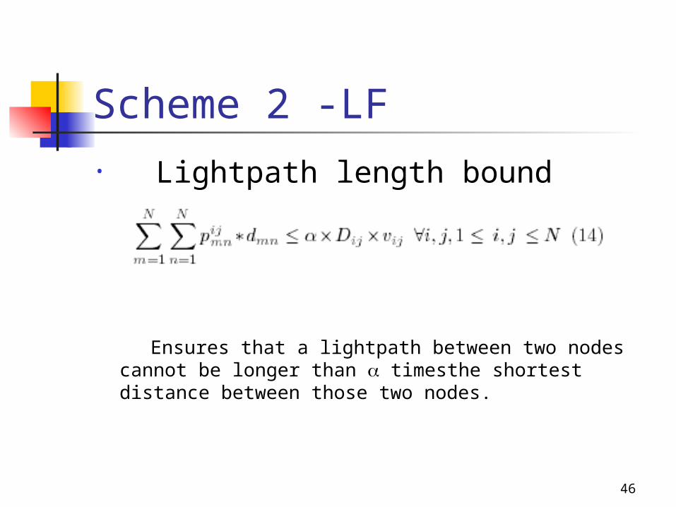
Scheme 2 -LF• Lightpath length bound
Ensures that a lightpath between two nodes cannot be longer than timesthe shortest distance between those two nodes.
47
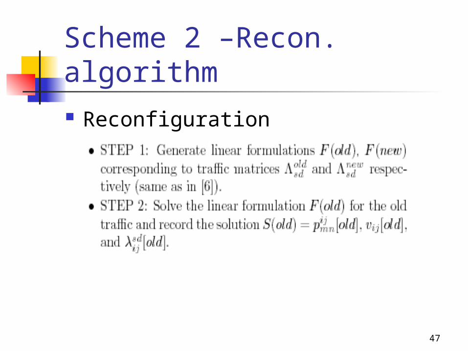
Scheme 2 –Recon. algorithm Reconfiguration

48
Scheme 2 –Recon. algorithm
49
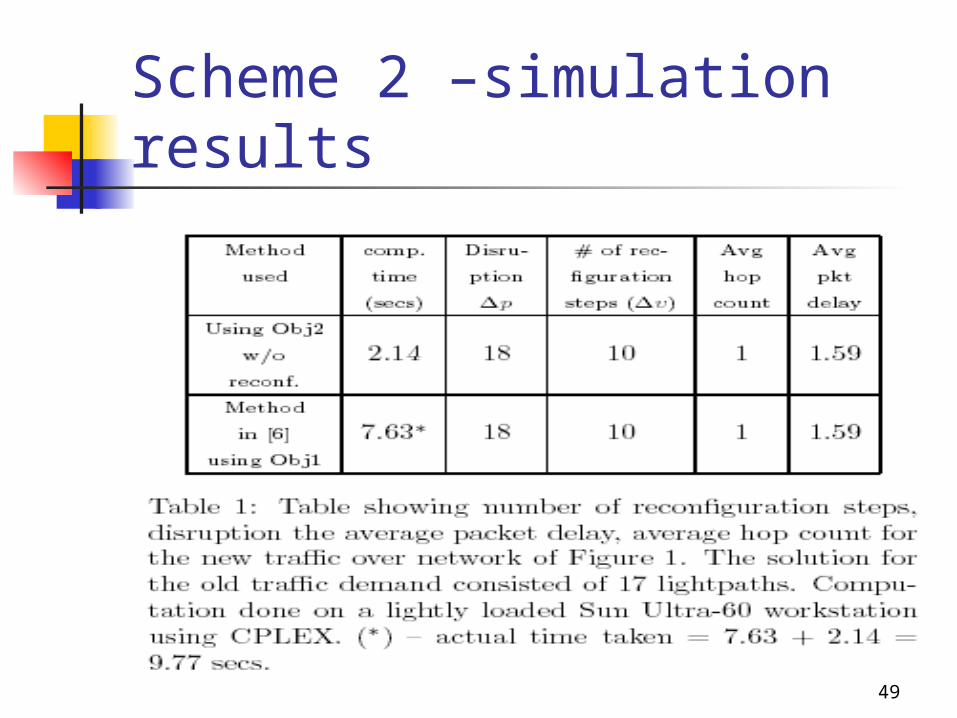
Scheme 2 –simulation results

50
Scheme 2 –simulation results

51
Scheme 2 -simulation results

52
Scheme 3 -overview Overview
• Traffic will be monitored systematically, central manager will collect data.
• Make decision to reconfigure• signaling• Reconfiguration process is seen as a continuous
measurement adaptation system where small adjustments are made, instead of waiting for a noticeable drop in system efficiency and changing the topology entirely.
• Hitless transition method: transition between topologies was achieved by first establishing all new links without removing any link. The links of the first topology were removed only when the traffic was rerouted through the links of the new topology.

53
Scheme 3 -approachOur approach: design the step adjustments
in a hitless manner, so that a change can be either a lightpath addition or a deletion (after rerouting the traffic using this virtual link).
• Network traffic is measured periodically.• Decide whether an adjustment is needed.
(addition or deletion)• This approach: only one lightpath change is
allowed at the end of each observation period.

54
Scheme 3 -MILP New parameters
• High watermark• Low watermark• At the end of an observation period, if the
load of one or more lightpaths is higher than , a new lightpath is established to decrease that load.
• When the load is dropped below than ,
that link will be torn down if aiternate paths exist for
diverting the traffic using that lightpath.
55
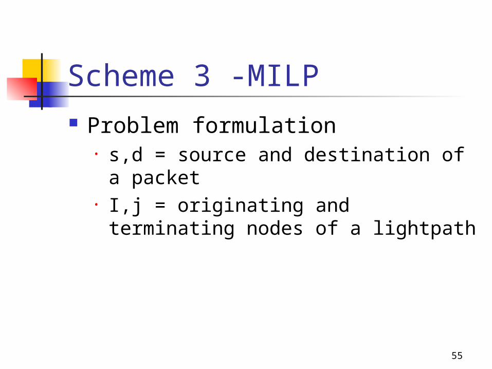
Scheme 3 -MILP Problem formulation
• s,d = source and destination of a packet
• I,j = originating and terminating nodes of a lightpath
56
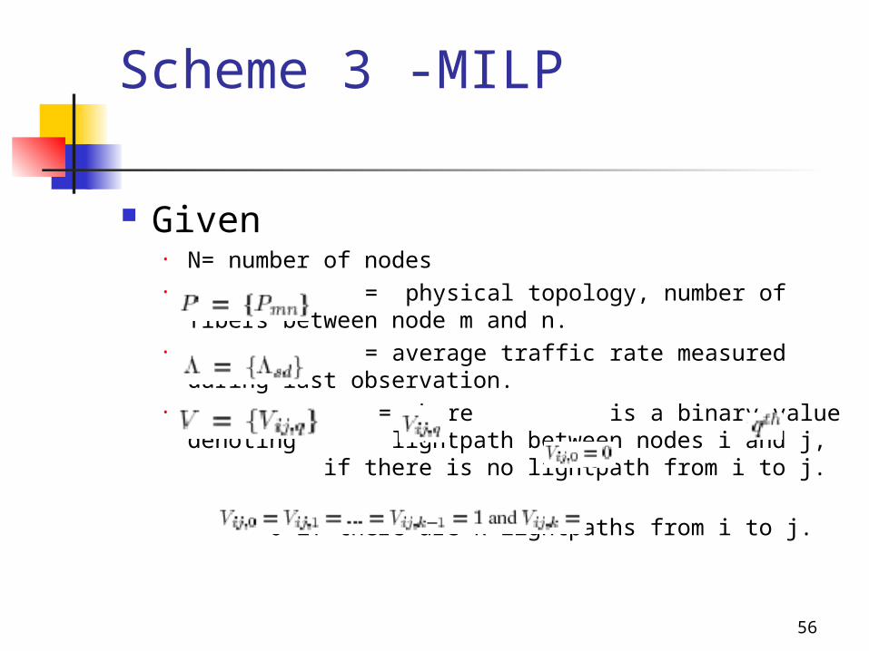
Scheme 3 -MILP
Given• N= number of nodes• = physical topology, number of fibers
between node m and n.• = average traffic rate measured during last
observation.• = where is a binary value denoting
lightpath between nodes i and j, if there is no lightpath from i to j.
0 if there are k lightpaths from i to j.

57
Scheme 3 -MILP• W = number of wavelengths on each fiber• C = Capacity of each wavelength channel• Ti = number of transmitter• Ri = number of receivers
• • • = highest and lowest lightpath
loads measured during the observation period

58
Scheme 3 -MILP Variables
• Physical routing binary variable if the lightpath from i to j is routed through the physical link (m,n)
• New virtual topology: is defined similar to . Note that V’ is at most one lightpath different from V.
• Traffic routing: The binary variable is 1 when the traffic flowing from node s to d employs as an intermediate lightpath, and 0 otherwise.
• Load of maximally-loaded lightpath in the network:
59
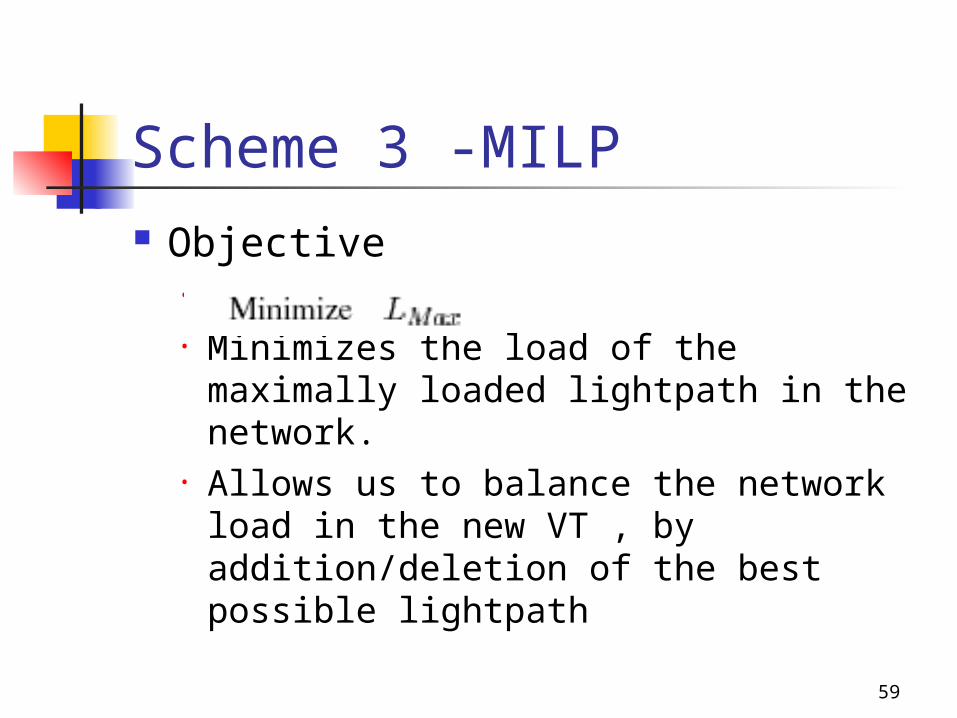
Scheme 3 -MILP Objective
• • Minimizes the load of the maximally
loaded lightpath in the network.• Allows us to balance the network load
in the new VT , by addition/deletion of the best possible lightpath

60
Scheme 3 -MILP Constraints
• On physical topology:• •
• (1) ensures that only one outgoing physical link of source
nodes will be assigned to a lightpath.• (2) ensures that only one incoming physical link of the
destination node will assigned to a lightpath

61
Scheme 3 -MILP
• (3) guarantees that the number of incoming and outgoing links reserved for a lightpath at any intermediate node will be equal.
• (4) number of wavelengths are limited to W on every physical link.
• (5) a physical link is assigned only if the lightpath exists.
62
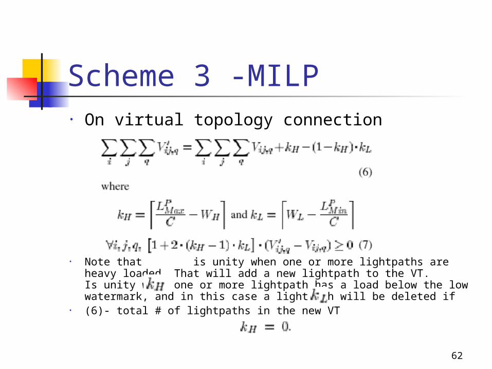
Scheme 3 -MILP• On virtual topology connection
• Note that is unity when one or more lightpaths are heavy loaded. That will add a new lightpath to the VT. Is unity when one or more lightpath has a load below the low watermark, and in this case a lightpath will be deleted if
• (6)- total # of lightpaths in the new VT
63
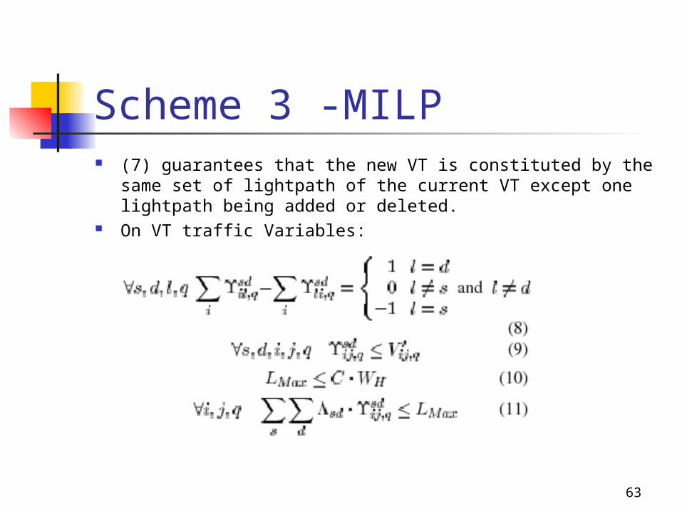
Scheme 3 -MILP (7) guarantees that the new VT is constituted by the same set
of lightpath of the current VT except one lightpath being added or deleted.
On VT traffic Variables:
64
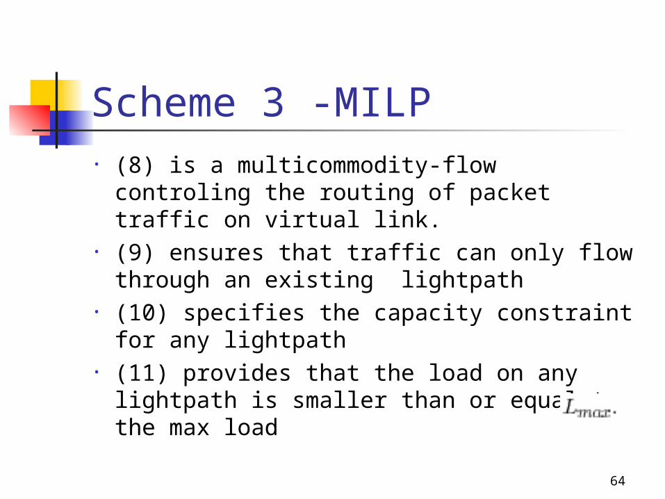
Scheme 3 -MILP• (8) is a multicommodity-flow controling
the routing of packet traffic on virtual link.• (9) ensures that traffic can only flow
through an existing lightpath • (10) specifies the capacity constraint for
any lightpath• (11) provides that the load on any
lightpath is smaller than or equal to the max load
65
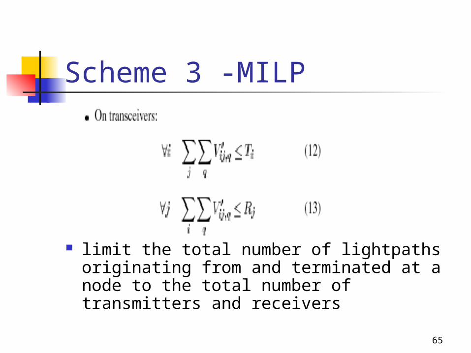
Scheme 3 -MILP
limit the total number of lightpaths
originating from and terminated at a node to the total number of transmitters and receivers
66
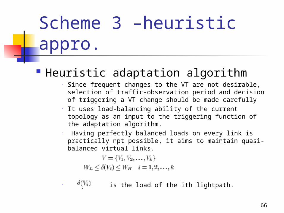
Scheme 3 –heuristic appro. Heuristic adaptation algorithm
• Since frequent changes to the VT are not desirable, selection of traffic-observation period and decision of triggering a VT change should be made carefully
• It uses load-balancing ability of the current topology as an input to the triggering function of the adaptation algorithm.
• Having perfectly balanced loads on every link is practically npt possible, it aims to maintain quasi-balanced virtual links.
• is the load of the ith lightpath.
67
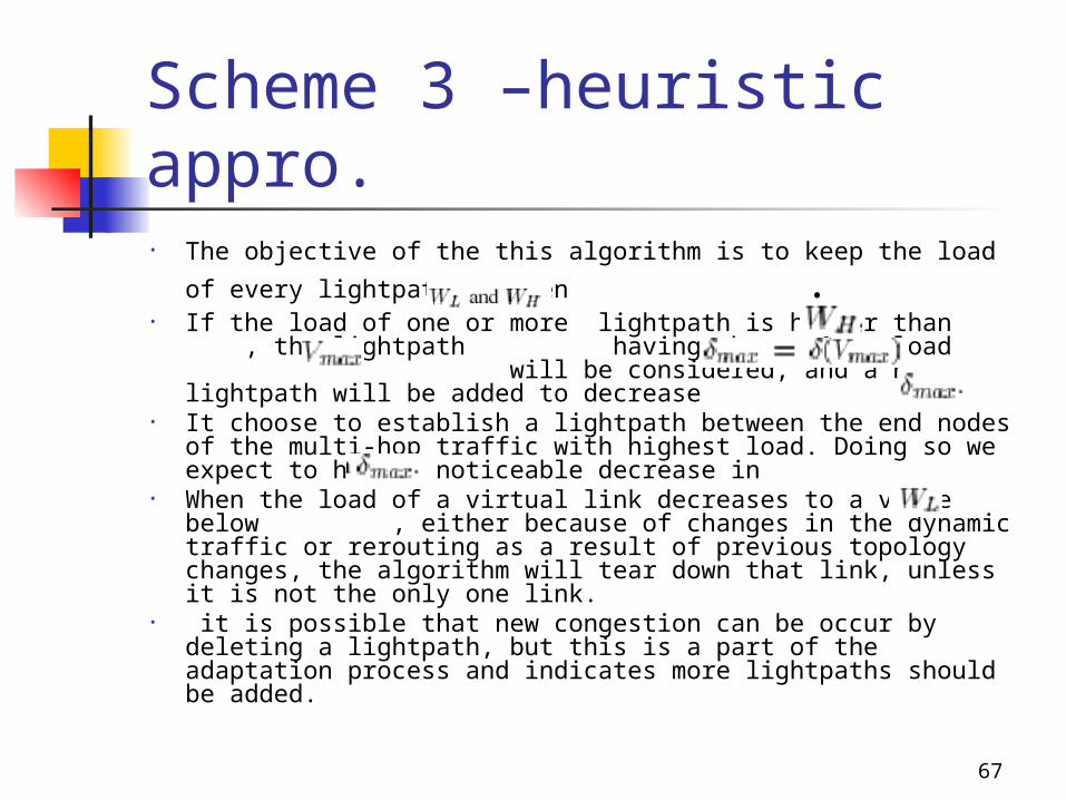
Scheme 3 –heuristic appro.• The objective of the this algorithm is to keep the load of every
lightpath between .• If the load of one or more lightpath is higher than , the
lightpath having the maximum load will be considered, and a new lightpath will be added to decrease
• It choose to establish a lightpath between the end nodes of the multi-hop traffic with highest load. Doing so we expect to have a noticeable decrease in
• When the load of a virtual link decreases to a value below , either because of changes in the dynamic traffic or rerouting as a result of previous topology changes, the algorithm will tear down that link, unless it is not the only one link.
• it is possible that new congestion can be occur by deleting a lightpath, but this is a part of the adaptation process and indicates more lightpaths should be added.
68
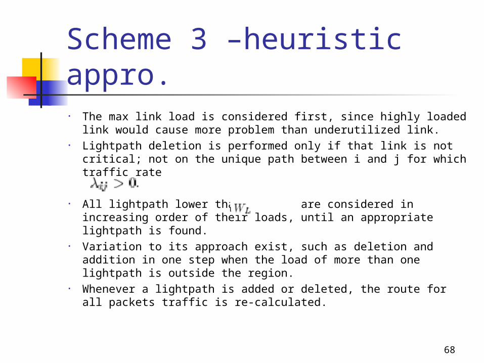
Scheme 3 –heuristic appro.• The max link load is considered first, since highly loaded
link would cause more problem than underutilized link.• Lightpath deletion is performed only if that link is not
critical; not on the unique path between i and j for which traffic rate
• All lightpath lower than are considered in increasing order of their loads, until an appropriate lightpath is found.
• Variation to its approach exist, such as deletion and addition in one step when the load of more than one lightpath is outside the region.
• Whenever a lightpath is added or deleted, the route for all packets traffic is re-calculated.
69
Scheme 3 -heuristic algo.
70
Scheme 3 –heuristic algo.

71
Scheme 3 –heuristic algo.
72
Scheme 3 –simulation results

73
Scheme 3 –simulation results
74
Scheme 3 –simulation results

75
Scheme 3 –simulation results

76
Scheme 3 –simulation results

77
Scheme 3 –simulation rsults
78
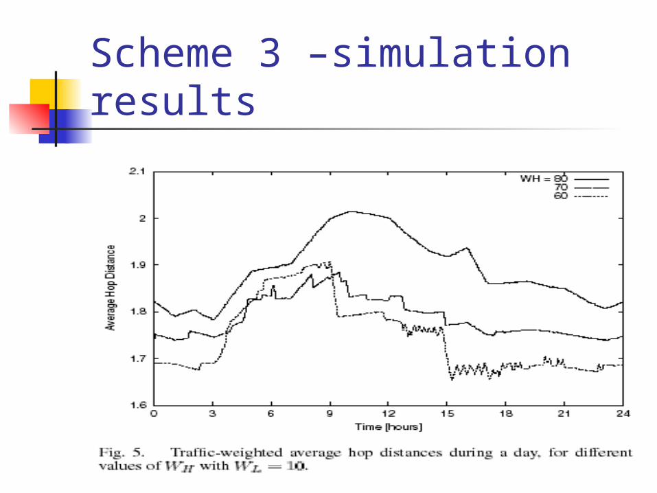
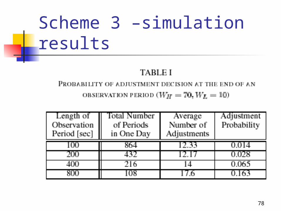
Scheme 3 –simulation results
79
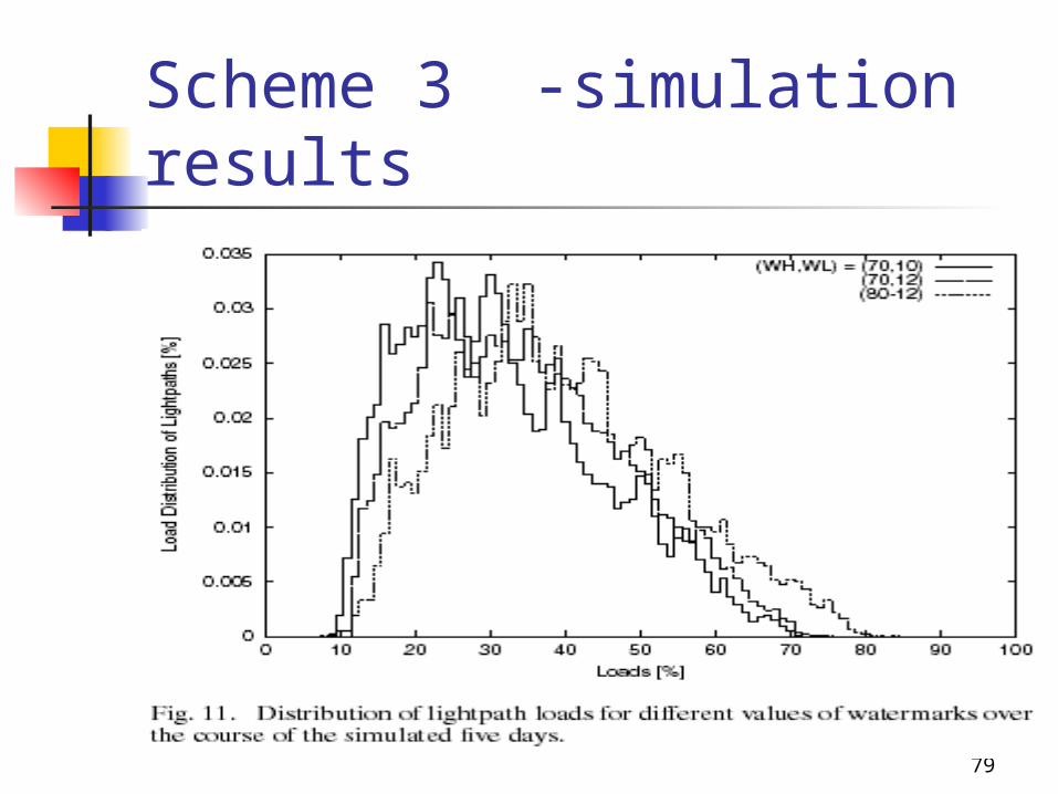
Scheme 3 -simulation results

80
Scheme 4 - overview A specific node may monitor transmissions on the
various channels, and apply statistical techniques to determine whether the overall conditions have changed in a way that significantly affects the optimality of the current wavelength assignment.
VT design GLPT- generalized LPT problem (multiprocessor scheduling
problem) - NP-hard Processor –> channels Tasks –> receivers Execution time –> bandwidth requirement Markov decision process formulation & policy-iteration
method

81
Scheme 4 -VT VT design
• (1) Objective is to assign the receivers to the available channels such that the total bandwidth used in each channel is approximately the same among different channels.
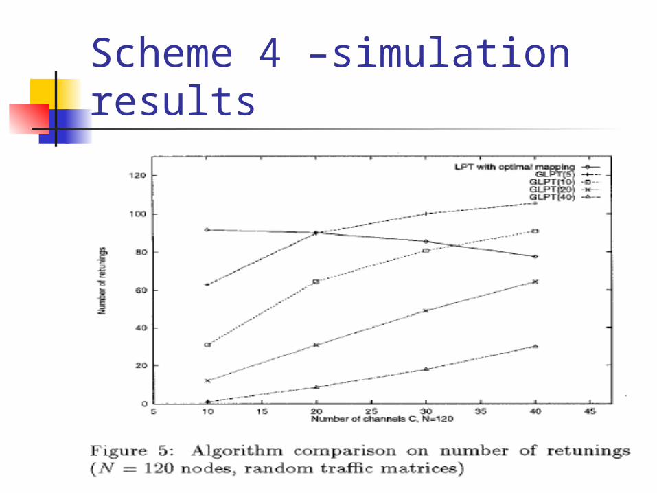
• (2) the number of retunings required to take the network from assignment R to R’ is as small as possible.
• This problem is equal to the multiprocessor scheduling. (NP hard)
82
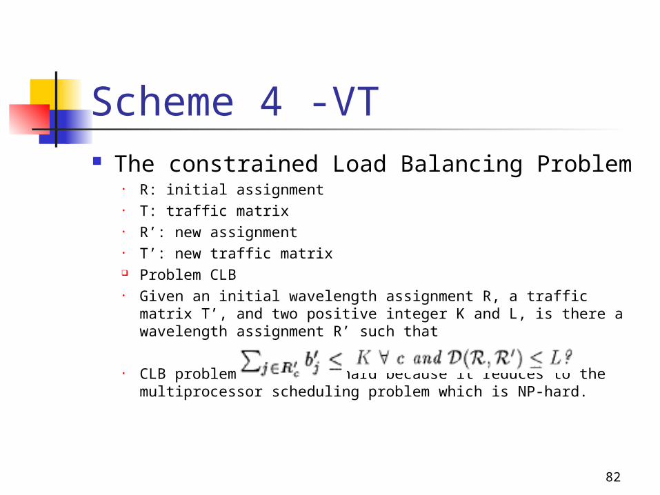
Scheme 4 -VT The constrained Load Balancing Problem
• R: initial assignment• T: traffic matrix• R’: new assignment• T’: new traffic matrix Problem CLB• Given an initial wavelength assignment R, a traffic matrix T’,
and two positive integer K and L, is there a wavelength assignment R’ such that
• CLB problem is also NP-hard because it reduces to the multiprocessor scheduling problem which is NP-hard.

83
Scheme 4 –heuristic appro. Heuristic based on CLB (GLPT)
• Approximation algorithm for the multiprocessor problem
• Processor= channels• Tasks= receivers• Execution time= bandwidth requirements
Modify LPT to take into account R, the previous wavelength assignment, by introducing a parameter ,
The new algorithm also orders the tasks in a list L in decreasing order of their bandwidth requirement.
When a channel i searches for a new receiver to assign it does not immediately take the first available receiver in the list.
84
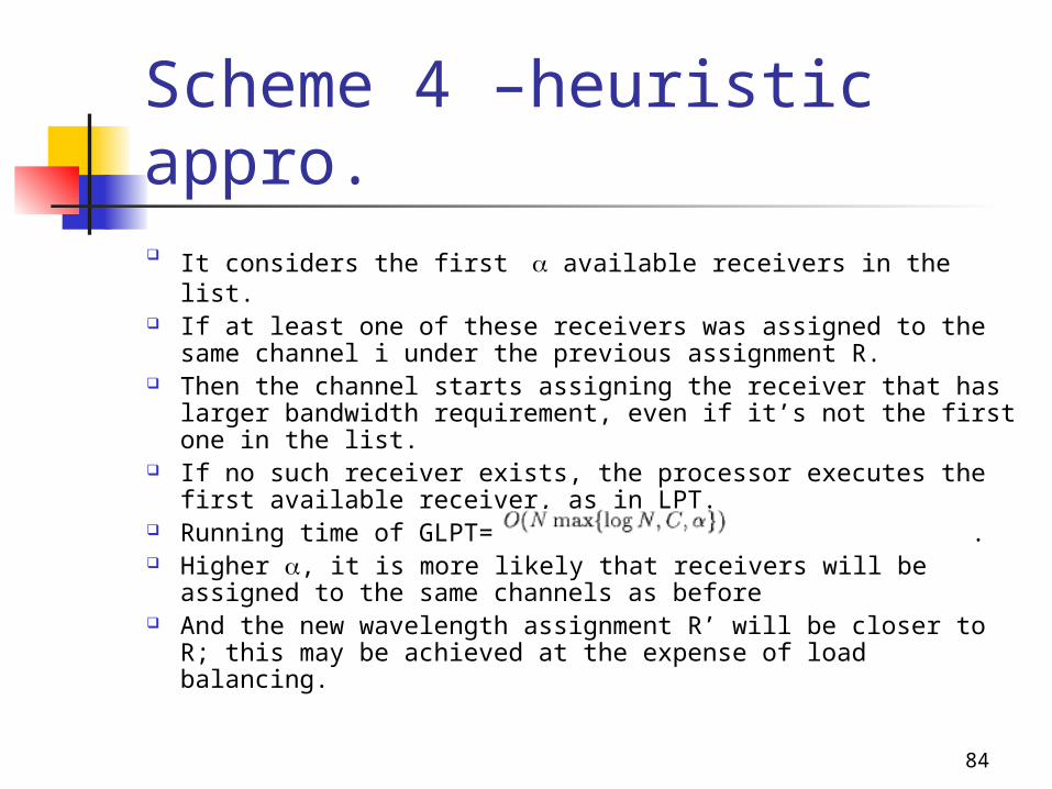
Scheme 4 –heuristic appro. It considers the first available receivers in the list. If at least one of these receivers was assigned to the
same channel i under the previous assignment R. Then the channel starts assigning the receiver that has
larger bandwidth requirement, even if it’s not the first one in the list.
If no such receiver exists, the processor executes the first available receiver, as in LPT.
Running time of GLPT= . Higher , it is more likely that receivers will be assigned
to the same channels as before And the new wavelength assignment R’ will be closer to
R; this may be achieved at the expense of load balancing.

85
Scheme 4 –GLPT algo.

86
Scheme 4 –GLPT algo.
87
Scheme 4 -simulation results
88
Scheme 4 –simulation results
89
Scheme 4 -simulation results
90
Scheme 4 –simulation results
91
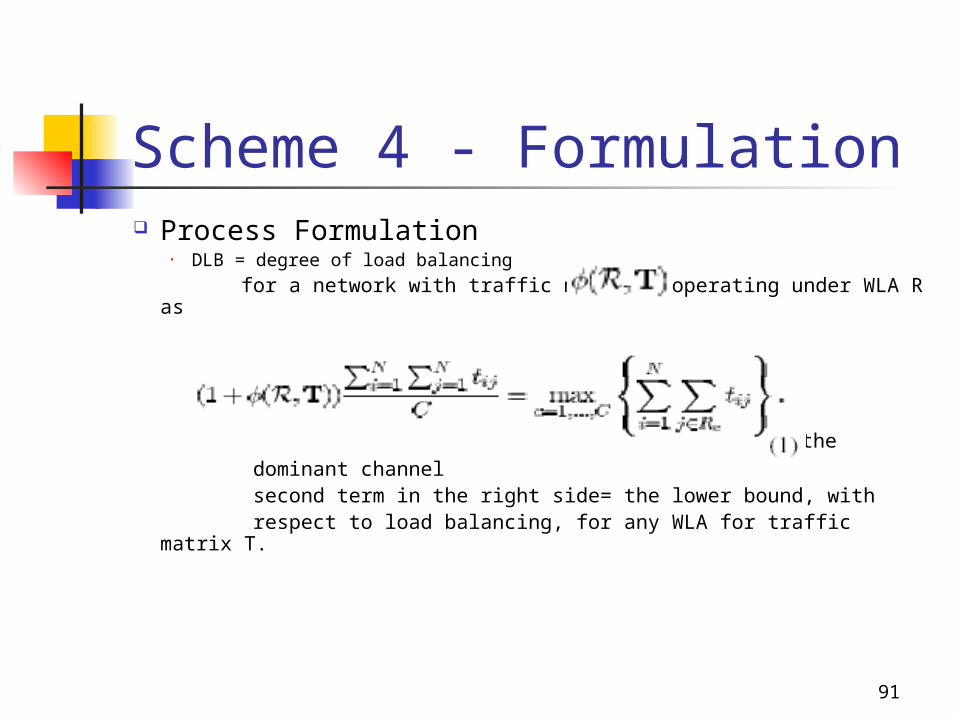
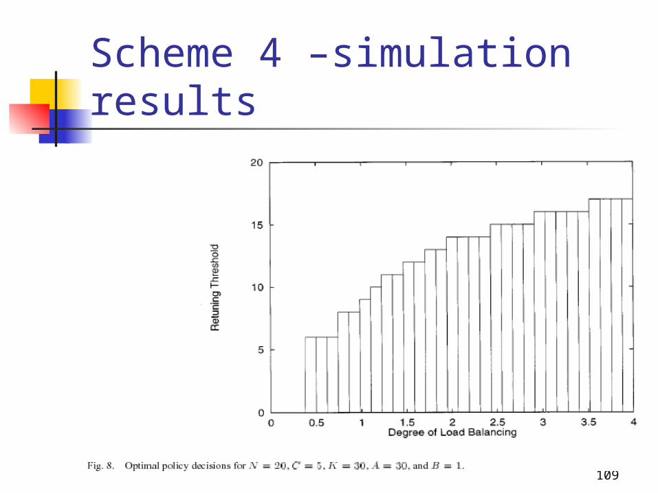
Scheme 4 - Formulation Process Formulation
• DLB = degree of load balancing
for a network with traffic matrix T operating under WLA R as
right-hand side= the bandwidth requirement of the dominant channel second term in the right side= the lower bound, with respect to load balancing, for any WLA for traffic matrix T.
92
Scheme 4 -Formulation is a measure of how far away wavelength
assignment R is from the lower bound. =0 , the load is perfectly balanced > 0, channels are not equally balanced Higher value means that inefficiency of the
network

93
Scheme 4 –MDP formulation Markov Decision Process Formulation
• Define the state of the network as a tuple (R,T)• R= current WLA• T= traffic matrix
• Assume that future traffic changes only depend on the current values of the elements of T, not the previous ones.
• So, the process (R,T) is a semi-Markov process• Let M be the process embedded at instants when the traffic
matrix changes. Then M is a discrete-time Markov process.• Our formulation is in terms of the Markov process M.• A network in state (R,T) will enter state (R’,T’) if the traffic matrix
changes to T’.

94
Scheme 4 -MDPF The decision is a function of the current state and is
denoted by d[(R,T)]. Setting d[(R,T)] = implies that if the system is in
state (R,T) and the traffic demands change, the network should be reconfigured into WLA .
can R or R’ So new state can be (R’,T’) or (R,T’) The set of decisions for all network states defines a
reconfiguration policy. To formulate the problem as a Markov decision process,
we need to specify reward and cost function associated with each transition.

95
Scheme 4 -MDPF Immediate expected reward: , (.) is a
nonincreasing function of Reconfiguration cost : , where (.) is a
nondecreasing function of the number of receivers that must be retuned.
We assume that the rewards and costs are bounded
The problem is how to reconfigure the network sequentially in time, so as to maximize the expected reward minus the cost over an infinite horizon.

96
Scheme 4 -MDPF• Z= set of admissible policies• Reconfiguration problem can be formally stated as follows
• The point at which this policy becomes optimal is not easy to determine, as it depends on the transition probabilities of the underlying Markov chain.
• Consider an ergodic, discrete-space discrete-time Markov process with rewards and a set of alternatives per state that affect the probabilities and rewards governing the process.
97
Scheme 4 -MDPF Policy-iteration algorithm can be used to obtain a policy
that maximize the long-term reward in (3) for such a process.
Initial, an arbitrary policy is specified from which all state transition rates are determined.
The algorithm then enters its basic iteration cycle, which consists of two stages.
The first stage is the value-determination operation, which evaluates the current policy.
The second step: the policy-improvement routines uses a set of criteria to modify the decision at each state and obtain a new policy with higher reward than the original policy.
This policy will be used as the starting point for the next iteration

98
Scheme 4 -MDPF The cycle continues until the policies in two successive
iterations are identical. At this point, algorithm has converged, and the final
policy is guaranteed to be optimal with respect to maximizing the reward in (3).
Difficulty in applying the policy-iteration algorithm to the Markov process M
• Potential number of states (R,T) is too large• Alternative formulation

99
Scheme 4 –alternative formulation Alternative Formulation
Close examination of (3)
Reward and cost functions depend only on
not on actual values of traffic element or WLA involved.

100
Scheme 4 –alter. formulation New process as Markov process M We make the simplifying assumption that the decision
to reconfigure will also depend on the DLBs and the distance only.
• State: tuple ,where is the DLB achieved by the current WLA with respect to the current traffic matrix and D is the number of retunings required if the network were to reconfigure.
• It has Markovian property. has real number value• To apply policy-iteration algorithm, we need a discrete-
state process• So we quantize the value with interval k.• We have a new discrete-state process M’ with state
101
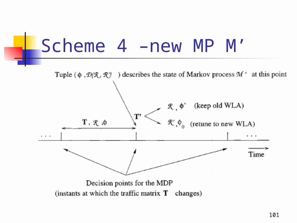
Scheme 4 –new MP M’

102
Scheme 4 –alter. formulation We note that GLPT algorithm guarantees that the DLB of
the WLA obtained using the algorithm will never be more than 50% away from the degree of load balancing of the optimal WLA.
Possible transition
103
Scheme 4 –alter. formulation The new process M’ is a discrete-space discrete-time
Markov process with rewards and two alternatives per state, and we can use the policy-iteration algorithm to obtain an optimal policy off-line and cache its decision
If under the optimal policy, the decision associates with current state is to reconfigure, then the network must make a transition to the new WLA R’; otherwise, the network will continue operating under the current WLA R.
We expect that as the number of interval K increases, the accuracy of the approximation will also increase, and the decision of the optimal policy obtained through the process
will converge.
104
Scheme 4 -transition Transition phase
receivers should be retuned. Retuning strategy: when and how? While retuning: possible increasing delay or packet loss
(penalty) Tradeoff between the length of the transition period and
the portion of the network that becomes unavailable during this period.
S, |S| = D(R,R’) Retuning strategy is defined as a partition of S into M,
1<=M<=|S|, subsets of receivers such that time is associated with subset
represents a group of receivers that are simultaneously taken off-line for retuning.
105
Scheme 4 -transition The retuning of group starts at time and lasts for
a period of time equal to the receiver retuning latency
L: maximum number of receivers in each group We note that a wide range of strategies can be obtained
for the different values of L. By varying the L value, we hope to determine whether
exists a tradeoff between the number of receivers that can be scheduled to retune at the same time and the associated packet losses during the transition phase.

106
Scheme 4 –retuning strategy

107
Scheme 4 –simulation results

108
Scheme 4 –simulation results
109
Scheme 4 –simulation results

110
Scheme 4 –simulation results
111
Scheme 4 -simulation results

112
Scheme 4 –simulation results

113
Scheme 4 –simulation results

114
Scheme 4 –simulation results

115
Scheme 4 –simulation results

116
Scheme 4 –simulation results

117
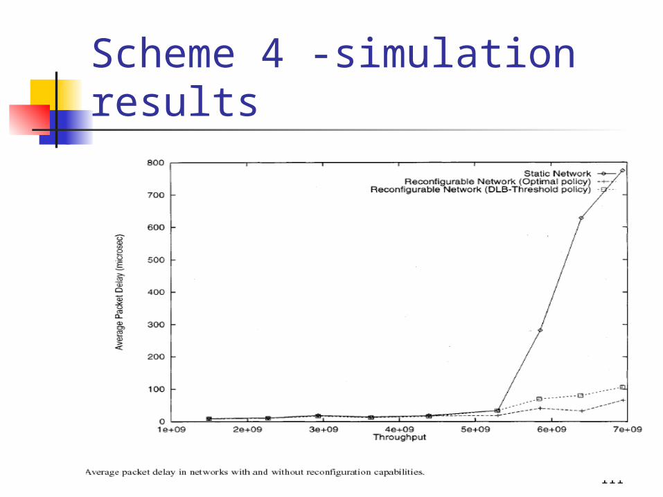
REFERENCES[1] I.Baldine and G.N.Rouskas, “Dynamic load balancing in broadcast
WDM networks with tuning latencies”, in Proc. INFOCOM ’98, Mar. 1998, p78-95
[2] B. Mukherjee, Optical Communication Networks, McGraw-Hill, July 1997
[3] D. Banerjee and B. Mukherjee, “Wavelength-routed optical networks: Linear formulation, resource budgeting tradeoffs, and a reconfiguration study”, IEEE/ACM Transaction on Networking, vol. 8, no. 5, pp. 598-607, Oct. 2000
[4] B. ramamurthy and A. Ramakrishnan, “Virtual topology reconfiguration of wavelength routed optical WDM networks”, in Proceedings of IEEE GLOBECOM, 2000, pp. 1269-1275
[5] I.Baldine and G.N.Rouskas, “Traffic adaptive WDM networks: A study of reconfiguration issues”, IEEE Trans. Commun.Jan, 2001
[6] A. Gencata and B. Mukherjee, “Virtual-Topology adaptation for WDM Mesh network under dynamic traffic”, IEEE Trans. Commun. 2002


