1
Senior Design Final Presentation
Stevens Institute of Technology
Mechanical Engineering Dept.
Senior Design 2005~06
Date: December 14th, 2005
Advisor: Dr. Kishore Pochiraju
Group 10:
Biruk Assefa, Lazaro Cosma,
Josh Ottinger, Yukinori Sato
2
Agenda
• Project Objective
• Progress Feedback
• Mathematical Model
• Device Assembly
• Component Designs
• Cost & Weight Budget
• Conclusion
3
Project Objective
Cable
Anchor
Rot. Gen.
Inv. Red. Dev.
Mech. Rect.
Reel + -Buoy
Selected Conceptual Design
• Project Description
– Design, develop, prototype and test a device that harnesses wave energy to generate electrical power on a buoy
– Off-shore location requires buoy to be self-sustaining
– Power output in the 100’s of Watts range
• Objectives
– Functional wave power generator which meet initial requirements
4
Progress Feedback• Identify losses in system
– Mechanical Components Mechanical Losses• Need for low number of components• Necessity of proper lubrication
– Gearbox issues• Using gearbox to increase speed affects inertia by the ratio
squared• As will be seen, ↑ Ratio:
– Increases torque losses– Reach a point where the system is unable to overcome inertia
• Impact of Model on the Design– Aid in sizing of several parameters: Buoy diameter,
Reel radius, spring constant, gear ratio– How each variable affects overall system– Sensitivity of each variable
5
Mathematical Model
• Systems Approach to Mathematical Model– Divided overall simulation into 6 subsystems – Identified by system components
• Within each subsystem includes detailed modeling of the governing equations
• Simulation is solved by the simultaneous computation of each equation
• To simplify the analysis the “engaged” case was analyzed
8
Buoy Design• Buoyant force is the main driving force• Other forces: resistance from other components,
weight, & damping force• Damping force is a function of buoy velocity• Buoy height (yellow) vs. Wave height (pink)
deviceF WdragF
bF
gyyAyyfF bwbwb )(),(
bdevicedampb yg
WFWFF "
bdragdrag yCF '
9
Buoy Design• Diameter of 6 feet • Height of 25 inches • Buoy Fabrication
– Commercially unavailable / Expensive– Using low density urethane foam– Laminated with fiber class for added strength– Mold Options:
• Manufactured at machine shop / sheet metal• Purchase kiddy pool
Mold Buoy
10
Spring Operated ReelFunction: Convert linear buoy
motion into rotational shaft motion
Design Aim: Maximize angular velocity of input shaft
Cable Tension (Fdevice ) lbs
Preload Length (inches)
50 60 70 80
K (inchpounds)
5 -494~1193 -421~1265 -349~1338 -194~990
10 -89~1035 10~1134 180~1232 206~1330
15 205~1735 408~1938 611~2142 815~2345
20 514~1982 777~2245 1049~2507 1302~2770
reelreelreelsprreeldevicereel ITTrF "
reelreel ",'
sprT reelT
deviceF
deviceF2
1deviceF
2
1
reelRreelI
bb yy ",'
reelpreloadbbspr ryykyfT )()( 0
2
4
6
8
10
12
14
16
Ma
xim
um
Su
bm
ers
ion
(i
nc
he
s)
50 60 70 80
Preload length
Maximum Submersion (yw – yb) Vs. Spring constant at various preload lengths
K = 5 inchpounds
K =10 inchpounds
K =15 inchpounds
K = 20 inchpounds
11
Spring Operated ReelDesign Variable Results
Diameter Max. Input Angular
velocity
3 inches 53 RPM
4 inches 40 RPM
5 inches 33 RPM
6 inches 28 RPM
Power Springs
Output Shaft to Rectifier
Support with Bearings
Spring Housing
Power Springs are attached to the shaft at their inner ends and fixed to the spring housing at the outer ends.
Power Springs
Output Shaft to Rectifier
Support with Bearings
Spring Housing
Power Springs are attached to the shaft at their inner ends and fixed to the spring housing at the outer ends.
12
Spring Operated Reel
Stand
Cable
SpringHousing Side plate
Shaft connection
Cable Guide
Reel Torque
Reel shaft angular velocity
Design Variables used
Wave Amplitude: 6 inchesWave Period: 7 secondsReel Diameter: 3 inchesSpring Constant: 10 inch poundsPreload length: 60 inches Buoy Diameter: 6 feet
13
Shaft Design• Maximum torque
located at reel output• Worst case scenario
– Full submersion– Locked shaft
• Torque on the shaft can be expressed as
• Factor of safety: 1.2reelbuoybuoyreelbuoyshaft grhrgrVT )(
2
1
2
1 2max,
Buoy Diameter Buoy Height Torque_shaftfeet feet Pound-inches 1 in OD 3/4 in OD 1/2 in OD
6 2.5 6,619 1.239 0.526 0.155 2 3,677 2.21 0.939 0.2684 1.5 1,765 4.809 2.043 0.583
Factor of Safety
14
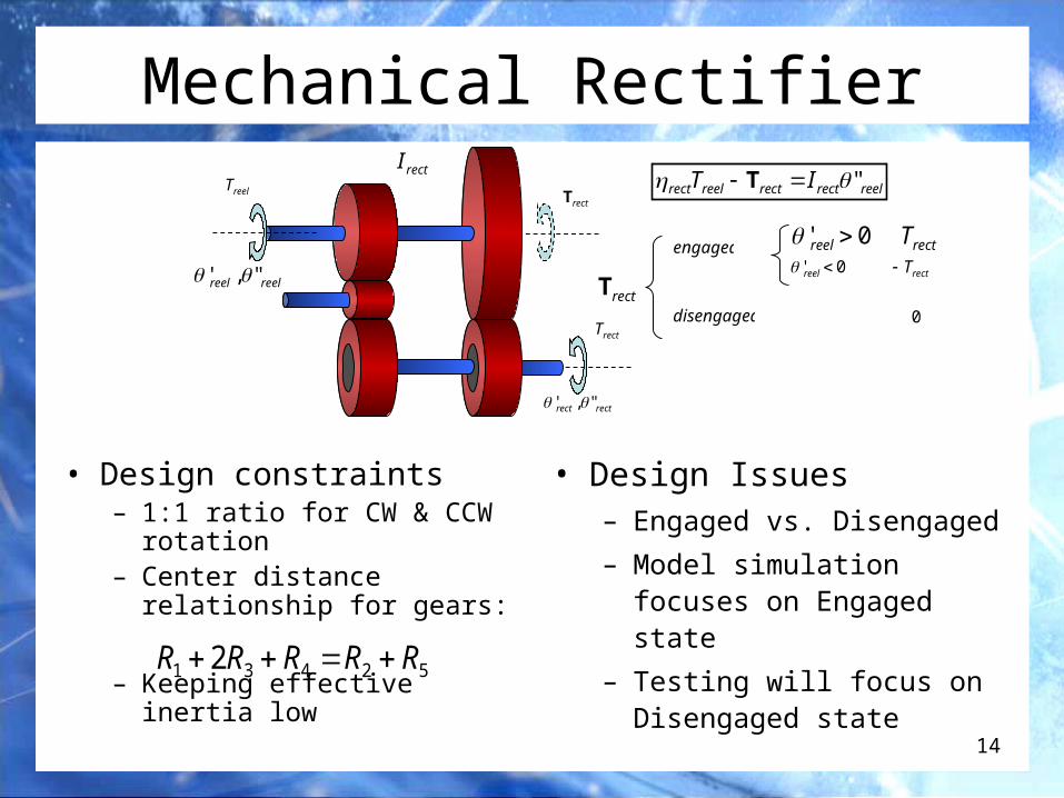
Mechanical Rectifier
• Design constraints– 1:1 ratio for CW & CCW
rotation– Center distance relationship
for gears:
– Keeping effective inertia low
reelrectrectreelrect IT " T
rectT
engaged
disengaged
0' reel0' reel
rectTrectT
0
reelTrectT
rectrect ",'
reelreel ",'
rectT
rectI
52431 2 RRRRR
• Design Issues– Engaged vs. Disengaged
– Model simulation focuses on Engaged state
– Testing will focus on Disengaged state
15
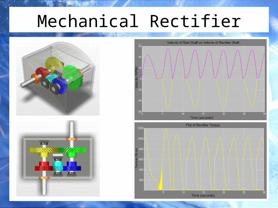
Mechanical Rectifier
16
Gear Box• Function: Speed up rotational
shaft motion
• Design Aim: Minimize gear ratio
Gear ratioGearbox Inertia
(slugs.in2)RPMmax after
Gearing
1:1 0.0335 37
1:5 0.3895 274
1:10 0.6372 535
1:15 1.8853 1074
1:20 1.8807 1500
Gear Ratio vs. Effective Inertia of GB, FW, & ALT (slugs.in^2)
0
50
100
150
200
250
300
350
400
450
500
0 5 10 15 20
Gear Ratio
Eff
ec
tiv
e I
ne
rtia
(s
lug
,in
^2
)
recteffectivegbgbrectgb IGTT ",
rect"
rect; rect;
rect' gb"gb'
rectTgbT
17
Gear Box
Input Shaft
Output Shaft
Design Variables used
Reel Diameter: 3 inchesSpring Constant: 10 inch poundsPreload length: 60 inches Buoy Diameter: 6 feetGear Ratio: 10
Angular velocity of Reel vs. Gear Box
Gearbox Torque
18
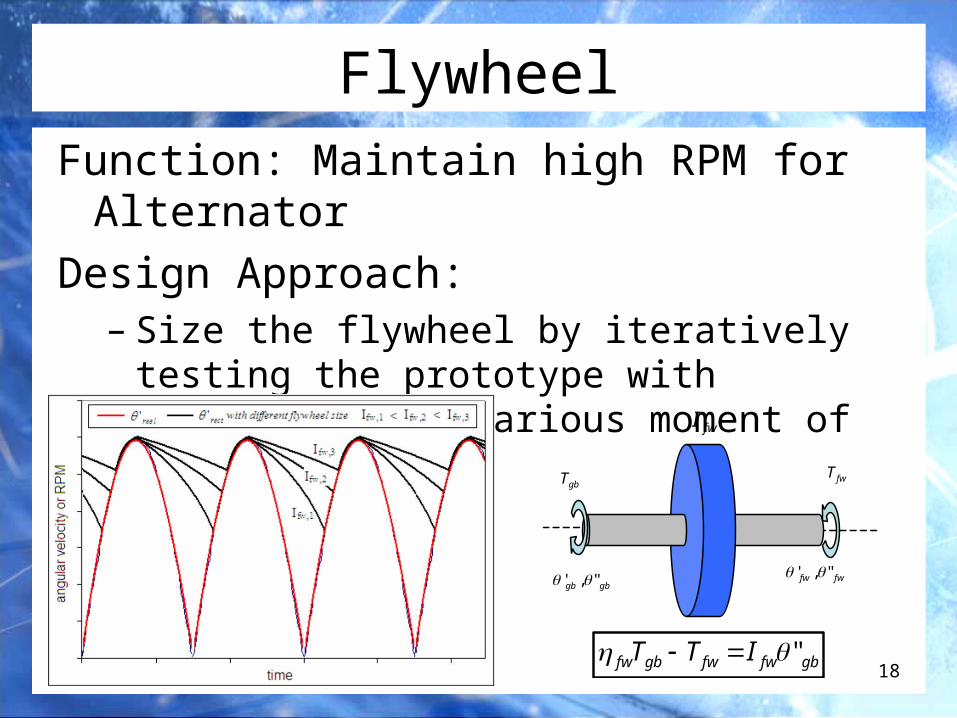
FlywheelFunction: Maintain high RPM for Alternator
Design Approach: – Size the flywheel by iteratively testing the
prototype with flywheels with various moment of inertia
gbfwfwgbfw ITT "
fwT
fwI
gbT
gbgb ",' fwfw ",'
19
AlternatorFunction: Produce electrical power
Design Approach: – Low inertia, high efficiency at low RPM, and variable torque
preferred– Test for Torque vs. RPM and Efficiency vs. RPM curves
fwaltemffwalt ITT "
cbafT fwfwfwemf ')'()'( 2
fwfwpoweraltfw TfPower ')'( ,
fwT emfT
altI
20
Alternator
• Permanent Magnet Alternator– Wind industry– High efficiency at low RPM (~300RPM)
• Variable EMF Alternator is chosen • Car Alternator will be used for
prototype testing:– Inexpensive– Low efficiency at low RPM
DC Generator Permanent Magnet Alternator Variable EMF Alternator
Inexpensive Relatively expensive Inexpensive
Typically for medium to high RPM range operation – range limited
Custom-made available for low RPM range operation
Typically for high RPM range operation
Fixed torque vs. RPM profile Fixed torque vs. RPM profile Variable EMF – torque can be adjusted
No current needed to energize the rotor No current needed to energize the rotor Small current needed to energize the rotor
Not controllable Not controllable EMF controllable with microcontroller
Not robust – commutator and brush Robust – does not use slip ring/brush May be less robust – use slip ring
21
Method of Control• Purpose: To maintain high power output by maintaining high RPM• Microcontroller – provides programmable, digital control
– Monitor two inputs (voltage and RPM)– Use PWM to adjust effective rotor EMF
• Use encoder to monitor RPM• Will be limited to basic control (such as P-control) in this project
Typical alternator regulator
Encoder setup at Flywheel
22
Battery Subsystem
• Car battery: provide large amount of current for a short period
• Deep cycle battery: provide steady current over a long period– Frequent charging and discharging
capable– Optimal for the case of renewable
energy generation
• Regulate charging voltage– Utilize regulator placed between
alternator & battery– Keep charging at consistent rate
during the wave profile
23
Power Output
Design Variables Values
Buoy Diameter 6 ft
Weight 250 lbs
Cable Preload Length 60 in
Reel Radius 1.5 in
Gear Ratio 10
Alternator Torque 40 lbs
• The Mathematical Model was run with determined design variables
• Efficiency of alternator assumed to be 50%• Higher average power expected with Flywheel
Predicted Power Output
24
Cost & Weight BudgetComponent Qty/Unit $/Unit Estimated Cost Estimated Weight (lbs)
Buoy - - - -Buoy Mold 1 40.00$ 40.00$ -Urethane Spray Foam 1 300.00$ 300.00$ 80
Waterproof Casing (ft2) 18 4.00$ 72.00$ 5Platform 1 15.00$ 15.00$ 30Spring-Reel 1 50.00$ 50.00$ 151/8” cable (ft) 20 2.00$ 40.00$ 5Mechanical Rectifier - - - 10
Gears 5 50.00$ 250.00$ -Bearings 5 15.00$ 75.00$ -Unidirectional Clutch 2 10.00$ 20.00$ -Shaft (ft) 6 15.00$ 90.00$ -
Plastic Covering (ft2) 12 4.00$ 48.00$ -Gear and Shaft Grease (tube) 1 5.00$ 5.00$ -
Gearbox 1 100.00$ 100.00$ 10Flywheel Disk 1 20.00$ 20.00$ 10Alternator 1 200.00$ 200.00$ 20Deep Cycle Battery 1 125.00$ 125.00$ 50Electrical Control 1 10.00$ 10.00$ -Microcontroller 1 40.00$ 40.00$ -Wiring (ft) 10 0.25$ 2.50$ -O-rings / Sealers 12 1.00$ 12.00$ -Bolted Anchor 1 10.00$ 10.00$ -Nuts and Bolts 30 0.25$ 7.50$ -Overhead at 25% of Direct Cost - - 383.00$ -
Totals 1,915.00$ 235
25
Conclusion• What we learned from ME 423:
– Necessity for Project Management
– Importance of detailed design
• ME 423 & E 421:– Connect Product design, marketing, & sales
– Basic understanding of intellectual property
• Initial plan to purchase COTS – Need to custom make several components
• Focus in ME 424:– Purchasing / Fabrication
– Final Assembly
– Testing Phase
26
Questions and Comments?
THANK YOU FOR LISTENING!
SEE YOU NEXT SEMESTER