74
1 Simple and Flexible 1 Corecess 5424 System Your Success is Corecess Apr. 2003 Technical Support Center Tel : +82-2-3016-6900 Fax : +82-2-3016-6955 E-Mail : [email protected]
| Date post: | 31-Dec-2015 |
| Category: |
Documents |
| Upload: | clinton-fleming |
| View: | 216 times |
| Download: | 0 times |

1
Simple and Flexible
1
Corecess 5424 SystemYour Success is Corecess
Apr. 2003
Technical Support Center
Tel : +82-2-3016-6900
Fax : +82-2-3016-6955
E-Mail : [email protected]
2
Simple and Flexible
2
Simple and Flexible
Table of Contents
I. System Architecture
II. Configuration CCS5424
III. Routing Protocol Configuration
IV. Multicast Protocol
Configuration
3
Simple and Flexible
3
Simple and Flexible
I. System Architecture
CCS5424 OverviewArchitecture
4
Simple and Flexible
4
Your Success is Corecess
4
CCS5424 OverviewCCS5424 Overview
Corecess 5424 is a multilayer switches that provide high availability, quality o
f service(Qos), and security to enhance network operation
With a range of Fast Ethernet and Gigabit Ethernet configurations, the CCS54
24 is a powerful option for enterprise and metro access applications.
12.8Gbps non blocking switching fabric modular L2/L3/L4 switch
19 million pps L3 forwarding rates
Product Overview
5
Simple and Flexible
5
Your Success is Corecess
5
Product Overview
CCS5424 OverviewCCS5424 Overview
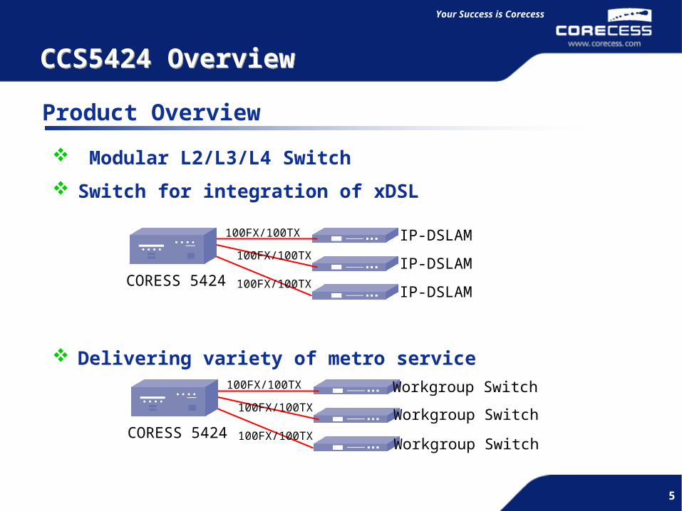
Modular L2/L3/L4 Switch
Switch for integration of xDSL
Delivering variety of metro service
Workgroup Switch
CORESS 5424
100FX/100TX
100FX/100TX
100FX/100TX
Workgroup Switch
Workgroup Switch
IP-DSLAM
IP-DSLAM
IP-DSLAMCORESS 5424
100FX/100TX
100FX/100TX
100FX/100TX
6
Simple and Flexible
6
Your Success is Corecess
6
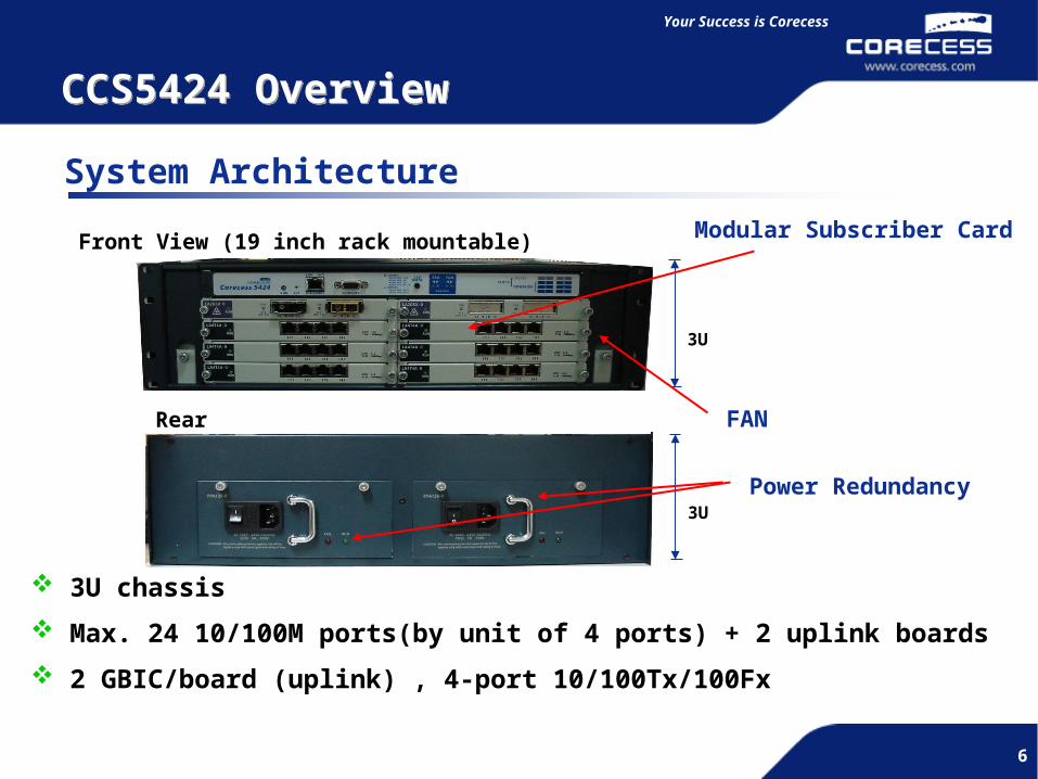
System Architecture
CCS5424 OverviewCCS5424 Overview
Front View (19 inch rack mountable)
3U
Rear View
3U
Modular Subscriber Card
FAN
Power Redundancy
3U chassis
Max. 24 10/100M ports(by unit of 4 ports) + 2 uplink boards
2 GBIC/board (uplink) , 4-port 10/100Tx/100Fx
7
Simple and Flexible
7
Your Success is Corecess
7
CCS5424 OverviewCCS5424 Overview
Key Feature and benefits – (1) System Feature
up to 24 10/100Base ports + 2 uplink boards [uplink] 2 GBIC/board
Switch/Processor module Switching capacity :12.8 Gbps 64bit RISC processor 256MByte system memory (SDRAM) supports 1 compact flash memory (128Mbytes) One Fast-Ethernet port for management (Out-bound) One console port (RS-232C, DSUB-9)
Ethernet I/O module (Phase-1) 10/100Tx 10/100Fx GBIC
8
Simple and Flexible
8
Your Success is Corecess
8
CCS5424 OverviewCCS5424 Overview
Key Feature and benefits – (2)
Flow Control Support (IEEE802.3x) Priority Support (IEEE 802.1p) Link Aggregation (Trunk,.IEEE802.3ad compliant) Port Mirroring IGMP Snooping with/without 802.1Q Tagging Multicast Supporting Per VLAN Spanning Tree Protocol Per VLAN (STP & RSTP) Rate limit (64Kps unit) Layer 3 Switching/Routing
9
Simple and Flexible
9
Your Success is Corecess
9
CCS5424 OverviewCCS5424 Overview
Key Feature and benefits – (3)
ProtocolsSNMP v1/v2c802.1d Spanning Tree Protocol802.1Q(VLAN Trunk)802.1p Priority Tagging : 8 levels802.3ad Link AggregationRapid Spanning Tree Protocol(RSTP)GVRP(GARP VLAN Registration Protocol)IP : RIP v1/v2, OSPF, BGP v2/v3/v4 (future support)Multicast : IGMP

10
Simple and Flexible
10
Your Success is Corecess
10
CCS5424 OverviewCCS5424 Overview
Key Feature and benefits – (4)
Performance Switch Capacity : 12.8 Gbps Throughput : 19 Mpps
128 traffic class & 2048 Flow group supports
Management SNMP v1/v2c RMON groups 1(statistics), 2(history), 3(alarm), and 9(events) and Extended RMON RFC 1493 Bridge MB RFC 2674 802.1Q Bridge MIB Remote Code Upgrade Support Management Console (RS-232), Telnet and Web Console Support FAN Control with FAN Fail Monitor Temperature and Power Supply Monitor Link/Activity/Speed LED in 10/100Base-TX Port & Power/RUN/Fault System LED
11
Simple and Flexible
11
Your Success is Corecess
11
CCS5424 OverviewCCS5424 Overview
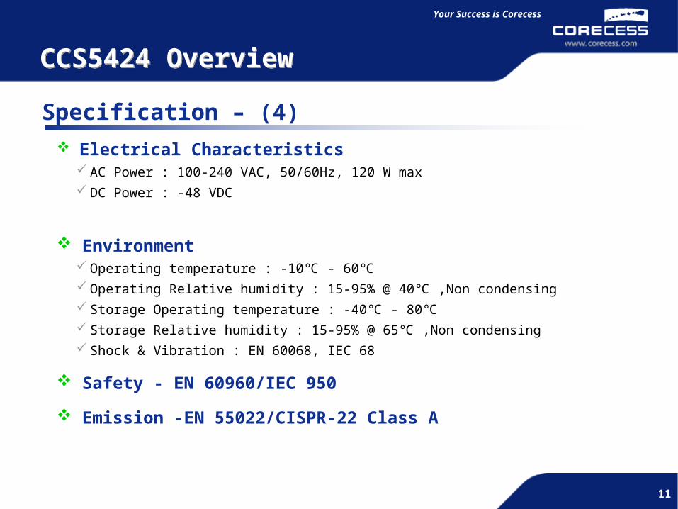
Specification – (4) Electrical Characteristics
AC Power : 100-240 VAC, 50/60Hz, 120 W max DC Power : -48 VDC
Environment Operating temperature : -10℃ - 60℃ Operating Relative humidity : 15-95% @ 40℃ ,Non condensing Storage Operating temperature : -40℃ - 80℃ Storage Relative humidity : 15-95% @ 65℃ ,Non condensing Shock & Vibration : EN 60068, IEC 68
Safety - EN 60960/IEC 950
Emission -EN 55022/CISPR-22 Class A
12
Simple and Flexible
12
Simple and Flexible
II. Configuration CCS5424VLAN & Tag VLANPort trunking, STP(RSTP)Specifying Maximum number of mac address

13
Simple and Flexible
13
Your Success is Corecess
13
System Upgrade
CCS5424 Basic Configuration
CCS5424 command is based on Cisco CLI command structure but not exactly same.
CCS5424Console Cable
Speed Data BIT Parity BIT Stop BIT Flow Control
38400 bps 8 bit None 1 bit None
DB9

14
Simple and Flexible
14
Your Success is Corecess
14
System Upgrade
CCS5424 Command Line Interface
Command Mode Explanation
Normal Mode
Default mode when CCS5424 is turned on. This mode can execute commands which only reads information of CCS5424.
Localhost login:root
Prompt : localhost >en
Privileged Mode
User changes to Privileged mode after entering administrator password (default – no password). This mode can verify all kind of configuration..
Prompt : localhost #d
Global Configuration
Mode
User can configure all kind of system values..
Prompt : localhost #configure terminal
localhost(config)#
15
Simple and Flexible
15
Your Success is Corecess
15
Basic Configuration
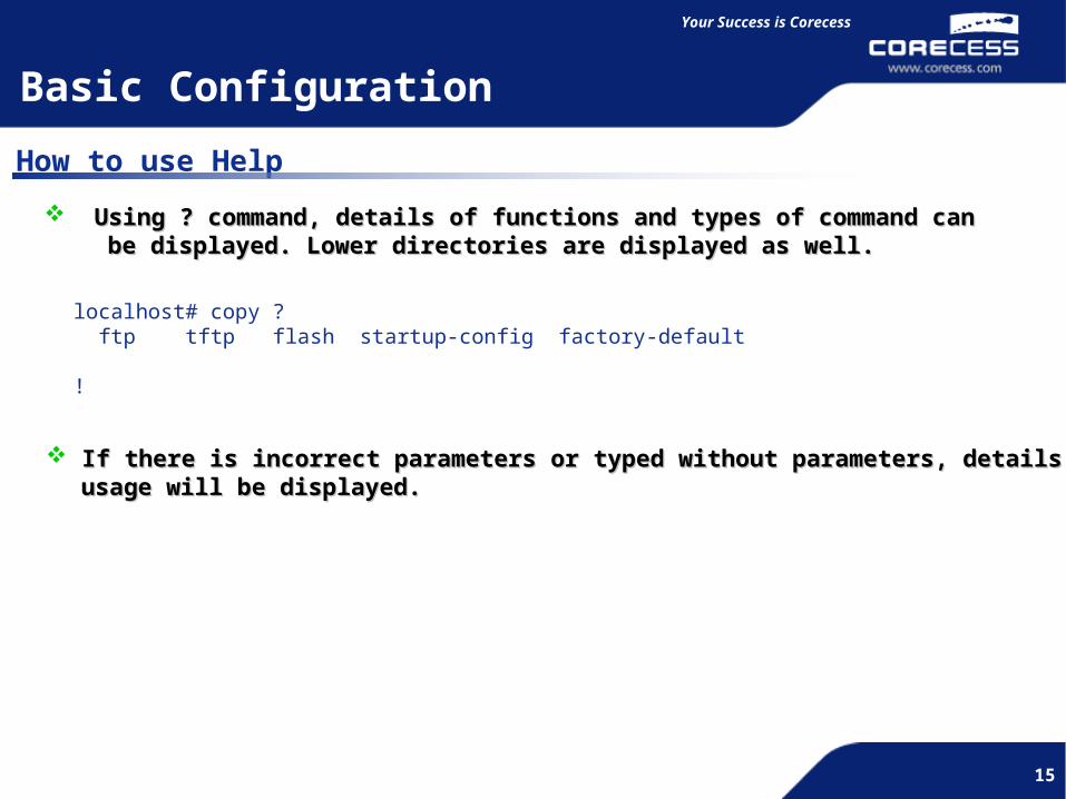
How to use Help
Using ? command, details of functions and types of command canUsing ? command, details of functions and types of command can be displayed. Lower directories are displayed as well. be displayed. Lower directories are displayed as well.
If there is incorrect parameters or typed without parameters, details ofIf there is incorrect parameters or typed without parameters, details of usage will be displayed. usage will be displayed.
localhost# copy ? ftp tftp flash startup-config factory-default
!
16
Simple and Flexible
16
Your Success is Corecess
16
System Upgrade
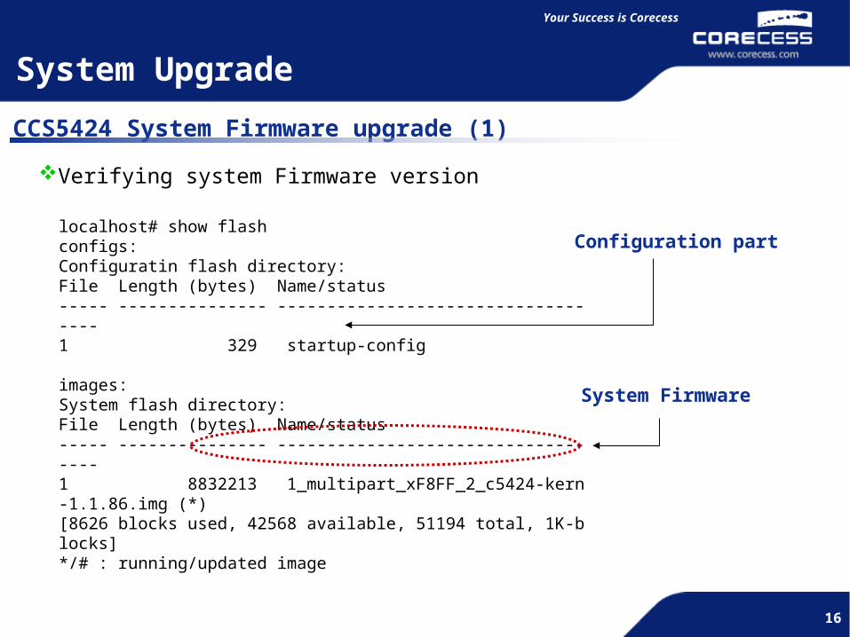
CCS5424 System Firmware upgrade (1)
Verifying system Firmware version
localhost# show flashconfigs:Configuratin flash directory:File Length (bytes) Name/status----- --------------- -----------------------------------1 329 startup-config
images:System flash directory:File Length (bytes) Name/status----- --------------- -----------------------------------1 8832213 1_multipart_xF8FF_2_c5424-kern-1.1.86.img (*)[8626 blocks used, 42568 available, 51194 total, 1K-blocks]*/# : running/updated image
Configuration part
System Firmware

17
Simple and Flexible
17
Your Success is Corecess
17
System Upgrade
CCS5424 System Firmware upgrade (2)
Download System Firmware from FTP/TFTP server to the System
FTP/TFTP Server
CCS5424Management IP address 10.1.1.10
10.1.1.1
Configuration StepConfigure CCS5424 management IP addressCopy F/W image from remote FTP/TFTP Server to the flash memoryUpdate new F/W image Reset system
18
Simple and Flexible
18
Your Success is Corecess
18
System Upgrade
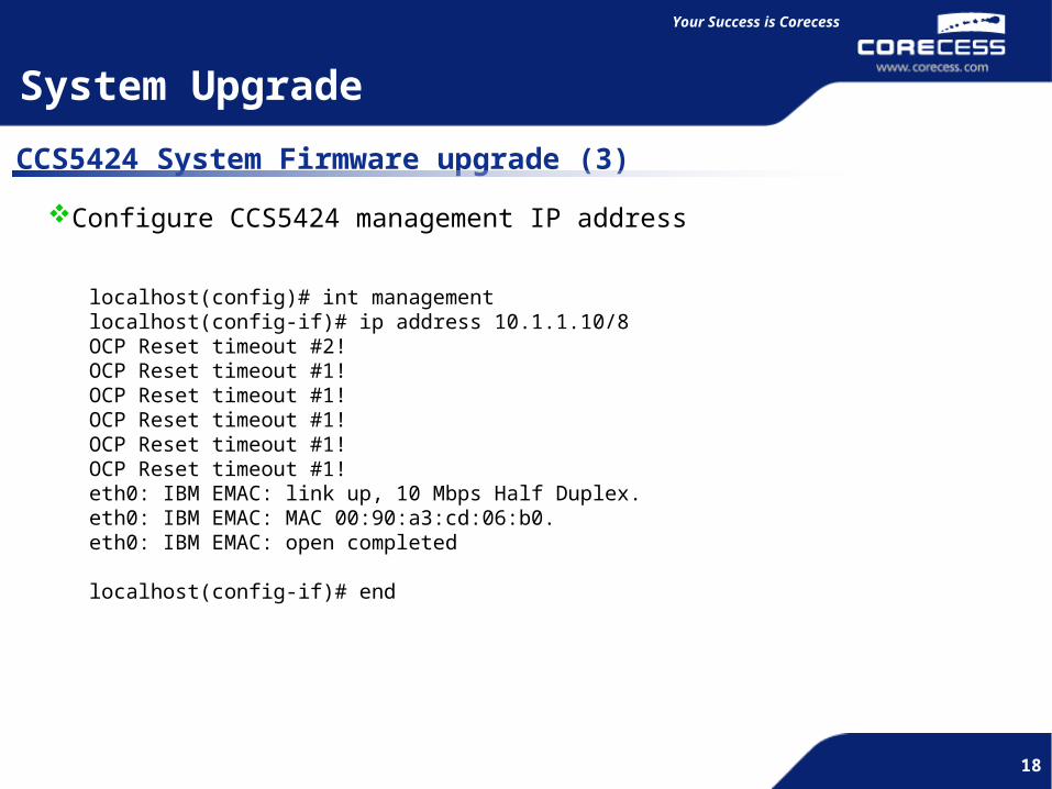
CCS5424 System Firmware upgrade (3)
Configure CCS5424 management IP address
localhost(config)# int managementlocalhost(config-if)# ip address 10.1.1.10/8OCP Reset timeout #2!OCP Reset timeout #1!OCP Reset timeout #1!OCP Reset timeout #1!OCP Reset timeout #1!OCP Reset timeout #1!eth0: IBM EMAC: link up, 10 Mbps Half Duplex.eth0: IBM EMAC: MAC 00:90:a3:cd:06:b0.eth0: IBM EMAC: open completed
localhost(config-if)# end
19
Simple and Flexible
19
Your Success is Corecess
19
System Upgrade
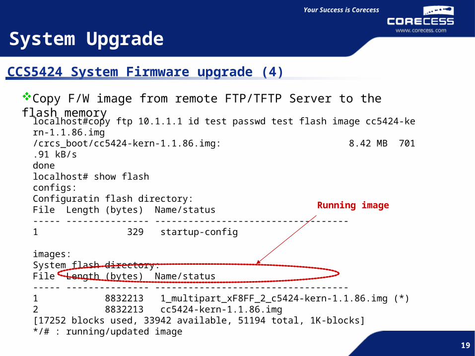
CCS5424 System Firmware upgrade (4)
Copy F/W image from remote FTP/TFTP Server to the flash memory
localhost#copy ftp 10.1.1.1 id test passwd test flash image cc5424-kern-1.1.86.img/crcs_boot/cc5424-kern-1.1.86.img: 8.42 MB 701.91 kB/sdonelocalhost# show flashconfigs:Configuratin flash directory:File Length (bytes) Name/status----- --------------- -----------------------------------1 329 startup-config
images:System flash directory:File Length (bytes) Name/status----- --------------- -----------------------------------1 8832213 1_multipart_xF8FF_2_c5424-kern-1.1.86.img (*)2 8832213 cc5424-kern-1.1.86.img[17252 blocks used, 33942 available, 51194 total, 1K-blocks]*/# : running/updated image
Running image
20
Simple and Flexible
20
Your Success is Corecess
20
System Upgrade
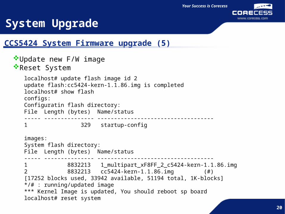
CCS5424 System Firmware upgrade (5)
Update new F/W imageReset System
localhost# update flash image id 2update flash:cc5424-kern-1.1.86.img is completedlocalhost# show flashconfigs:Configuratin flash directory:File Length (bytes) Name/status----- --------------- -----------------------------------1 329 startup-config
images:System flash directory:File Length (bytes) Name/status----- --------------- -----------------------------------1 8832213 1_multipart_xF8FF_2_c5424-kern-1.1.86.img2 8832213 cc5424-kern-1.1.86.img (#)[17252 blocks used, 33942 available, 51194 total, 1K-blocks]*/# : running/updated image*** Kernel Image is updated, You should reboot sp boardlocalhost# reset system

21
Simple and Flexible
21
Your Success is Corecess
21
VLAN
VLAN Overview
What is VLAN (Virtual LAN) ? Define Broadcast Domain at Layer 2 Network..
Broadcast Domain
Broadcast Domain
Broadcast Domain

22
Simple and Flexible
22
Your Success is Corecess
22
VLAN
VLAN Configuration
CCS5424
Router
INTERNET
File ServerOverlap Port
vlan2 vlan3 vlan4Port 1/1-3 Port 2/1-3 Port 3/1-3
Port 5/1 Port 6/1
vlan2 vlan4
23
Simple and Flexible
23
Your Success is Corecess
23
VLAN
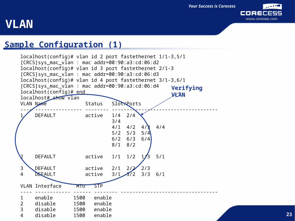
Sample Configuration (1)localhost(config)# vlan id 2 port fastethernet 1/1-3,5/1[CRCS]sys_mac_vlan : mac addr=00:90:a3:cd:06:d2localhost(config)# vlan id 3 port fastethernet 2/1-3[CRCS]sys_mac_vlan : mac addr=00:90:a3:cd:06:d3localhost(config)# vlan id 4 port fastethernet 3/1-3,6/1[CRCS]sys_mac_vlan : mac addr=00:90:a3:cd:06:d4localhost(config)# endlocalhost# show vlanVLAN Name Status Slot/Ports---- ---------------- -------- ------------------------------------1 DEFAULT active 1/4 2/4 3/4 4/1 4/2 4/3 4/4 5/2 5/3 5/4 6/2 6/3 6/4 8/1 8/2
2 DEFAULT active 1/1 1/2 1/3 5/1
3 DEFAULT active 2/1 2/2 2/34 DEFAULT active 3/1 3/2 3/3 6/1
VLAN Interface MTU STP---- ------------ ------ -------- ---------------------------------1 enable 1500 enable2 disable 1500 enable3 disable 1500 enable4 disable 1500 enable
Verifying VLAN
24
Simple and Flexible
24
Your Success is Corecess
24
VLAN
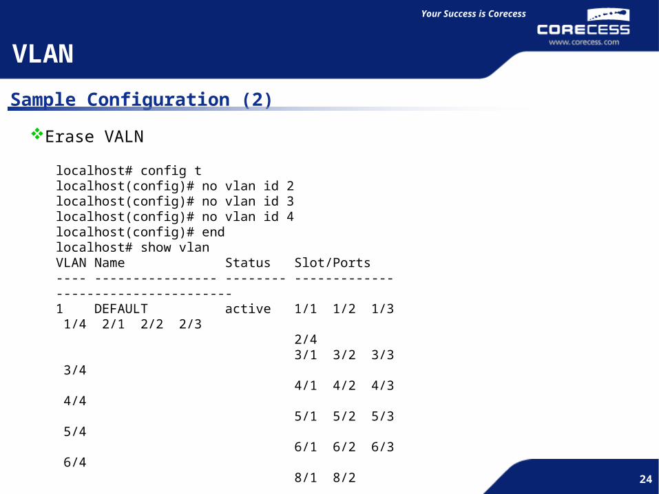
Sample Configuration (2)
Erase VALN
localhost# config tlocalhost(config)# no vlan id 2localhost(config)# no vlan id 3localhost(config)# no vlan id 4localhost(config)# endlocalhost# show vlanVLAN Name Status Slot/Ports---- ---------------- -------- ------------------------------------1 DEFAULT active 1/1 1/2 1/3 1/4 2/1 2/2 2/3 2/4 3/1 3/2 3/3 3/4 4/1 4/2 4/3 4/4 5/1 5/2 5/3 5/4 6/1 6/2 6/3 6/4 8/1 8/2
VLAN Interface MTU STP---- ------------ ------ -------- ---------------------------------1 enable 1500 enable
25
Simple and Flexible
25
Your Success is Corecess
25
VLAN
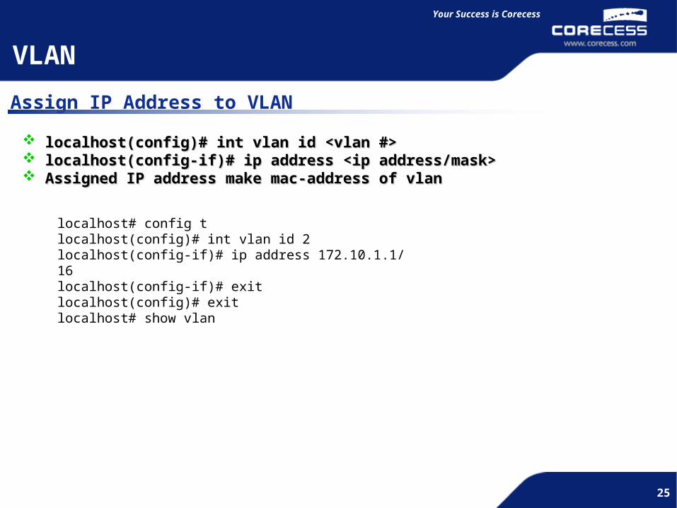
Assign IP Address to VLAN
localhost(config)# int vlan id <vlan #>localhost(config)# int vlan id <vlan #> localhost(config-if)# ip address <ip address/mask>localhost(config-if)# ip address <ip address/mask> Assigned IP address make mac-address of vlanAssigned IP address make mac-address of vlan
localhost# config tlocalhost(config)# int vlan id 2localhost(config-if)# ip address 172.10.1.1/16localhost(config-if)# exitlocalhost(config)# exitlocalhost# show vlan
26
Simple and Flexible
26
Your Success is Corecess
26
Tag VLAN
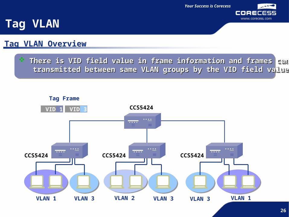
Tag VLAN Overview
VID 1 VID 3
Tag Frame
VLAN 1 VLAN 2 VLAN 3VLAN 3 VLAN 1VLAN 3
CCS5424
There is VID field value in frame information and frames can beThere is VID field value in frame information and frames can be transmitted between same VLAN groups by the VID field value. transmitted between same VLAN groups by the VID field value.
There is VID field value in frame information and frames can beThere is VID field value in frame information and frames can be transmitted between same VLAN groups by the VID field value. transmitted between same VLAN groups by the VID field value.
CCS5424 CCS5424 CCS5424

27
Simple and Flexible
27
Your Success is Corecess
27
VLAN 1VID=1
Tag Port
VLAN 1VID=1
Tag Port
VLNA 3VID=3
Tag Port
VLAN 4 VID=4
Tag Port
Multi Port Port A
VID=1,3,4
VID
4
VID
1
Encapsulate Tag Field information into a frame, and forward.Encapsulate Tag Field information into a frame, and forward. Encapsulate Tag Field information into a frame, and forward.Encapsulate Tag Field information into a frame, and forward.
Tag VLAN
Multi Port Progress
28
Simple and Flexible
28
Your Success is Corecess
28
Tag VLAN
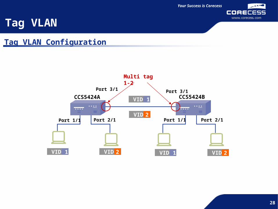
Tag VLAN Configuration
CCS5424A CCS5424B
VID 1 VID 2 VID 1 VID 2
Multi tag 1-2
VID 2
VID 1
Port 1/1 Port 2/1
Port 3/1 Port 3/1
Port 2/1Port 1/1

29
Simple and Flexible
29
Your Success is Corecess
29
Tag VLAN
Sample Configuration (1)localhost# config tlocalhost(config)# dot1q port fastethernet 1/1 tag VLAN TAG IDlocalhost(config)# dot1q port fastethernet 1/1 tag 1localhost(config)# dot1q port fastethernet 2/1 tag 2localhost(config)# dot1q port fastethernet 3/1 tag 1-2localhost(config)# endlocalhost# show dot1qPort allowed 802.1q VLAN TAGs-------- -----------------------------------------------------------------1/1 12/1 23/1 1-2
Verifying Tag VLAN
30
Simple and Flexible
30
Your Success is Corecess
30
Tag VLAN
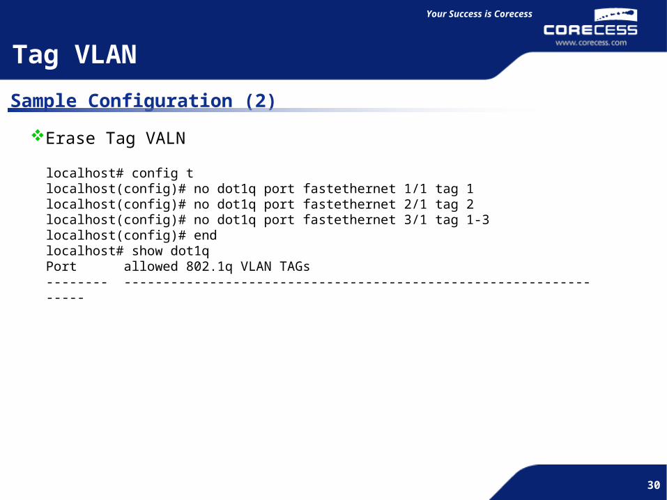
Sample Configuration (2)
localhost# config tlocalhost(config)# no dot1q port fastethernet 1/1 tag 1localhost(config)# no dot1q port fastethernet 2/1 tag 2localhost(config)# no dot1q port fastethernet 3/1 tag 1-3localhost(config)# endlocalhost# show dot1qPort allowed 802.1q VLAN TAGs-------- -----------------------------------------------------------------
Erase Tag VALN

31
Simple and Flexible
31
Your Success is Corecess
31
Port Trunk
Trunk Overview
Make Logical Port by using several Physical Port. Increase Bandwidth and
Offer Fault Tolerance.
Can make one Logical Port by using maximum of 4 ports.
Make Logical Port by using several Physical Port. Increase Bandwidth and
Offer Fault Tolerance.
Can make one Logical Port by using maximum of 4 ports.
If Trunk were not set, Loop would be occurred.
If Trunk were set, there is no Loop because ports works
as one.

32
Simple and Flexible
32
Your Success is Corecess
32
Port Trunk
Key Benifits Bandwidth incrementMake one Logical port by using two 100Mbps Physical Port, then it becomes 200Mbps Bandwidth
Fault toleranceFault Tolerance will be increased because even one of trunk ports is disconnected, still can communicate by using the other port.
CCS5424 CCS5424
100M x 2 = 200MEven one link is
disconnected, the other link will be
used.
33
Simple and Flexible
33
Your Success is Corecess
33
Port Trunk
Forwarding Method
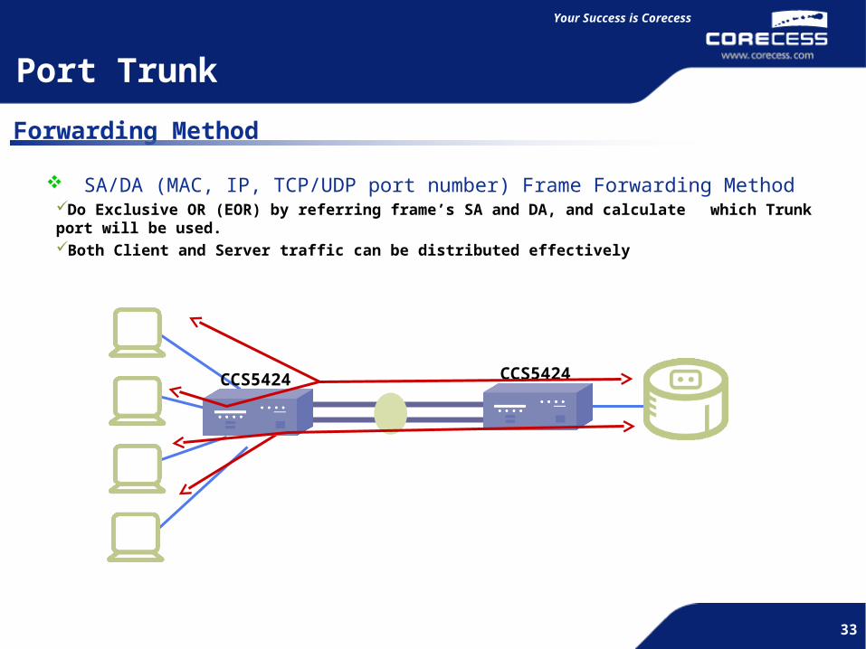
SA/DA (MAC, IP, TCP/UDP port number) Frame Forwarding MethodDo Exclusive OR (EOR) by referring frame’s SA and DA, and calculate which Trunk port will be used.Both Client and Server traffic can be distributed effectively.
CCS5424 CCS5424

34
Simple and Flexible
34
Your Success is Corecess
34
Port Trunk
Configuration
CCS5424 A CCS5424 B
100M x 4 = 200M
Port fastethernet 4/1- 4
Port fastethernet 4/1- 4

35
Simple and Flexible
35
Your Success is Corecess
35
Port Trunk
Sample Configuration(1)localhost# config tlocalhost(config)# lacp key 10 port fastethernet 4/1-4 mode manuallocalhost(config)# endlocalhost# show lacp lag allSlot/Port Receieve State Mux State ----------- ----------------- ----------------------- [ 4/ 1] CURRENT COLLECTING_DISTRIBUTING [ 4/ 2] CURRENT COLLECTING_DISTRIBUTING [ 4/ 3] CURRENT COLLECTING_DISTRIBUTING [ 4/ 4] CURRENT COLLECTING_DISTRIBUTING
Verifying Trunk

36
Simple and Flexible
36
Your Success is Corecess
36
Sample Configuration(2)
Port Trunk
localhost# config tlocalhost(config)# no lacp key port fastethernet 4/1-4localhost(config)# end
Erase Trunk

37
Simple and Flexible
37
Your Success is Corecess
37
STP (Spanning Tree Protocol)
STP Overview
Broadcast LoopsBroadcast
Frame Broadcast Storm !!!
Switch would be down or not be able to do other jobs because
CPU process all broadcast packets. Then, PCs will be down
later on.
STP : One of protocols which can prevent Loop. Choose the shortest path in the center of a switch.
STP : One of protocols which can prevent Loop. Choose the shortest path in the center of a switch.
38
Simple and Flexible
38
Your Success is Corecess
38
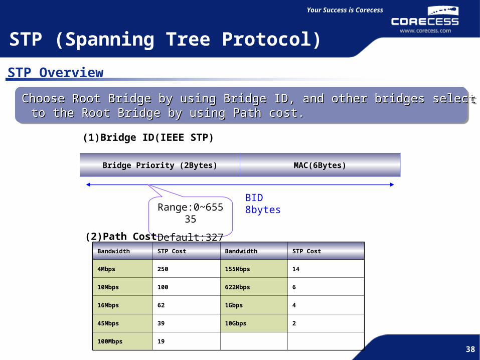
(1)Bridge ID(IEEE STP)
Bridge Priority (2Bytes) MAC(6Bytes)
BID 8bytesRange:0~65535
Default:32768(2)Path Cost
Bandwidth STP Cost Bandwidth STP Cost
4Mbps 250 155Mbps 14
10Mbps 100 622Mbps 6
16Mbps 62 1Gbps 4
45Mbps 39 10Gbps 2
100Mbps 19
Choose Root Bridge by using Bridge ID, and other bridges select the shortest path Choose Root Bridge by using Bridge ID, and other bridges select the shortest path to the Root Bridge by using Path cost. to the Root Bridge by using Path cost.
Choose Root Bridge by using Bridge ID, and other bridges select the shortest path Choose Root Bridge by using Bridge ID, and other bridges select the shortest path to the Root Bridge by using Path cost. to the Root Bridge by using Path cost.
STP (Spanning Tree Protocol)
STP Overview
39
Simple and Flexible
39
Your Success is Corecess
39
STP (Spanning Tree Protocol)
STP Overview
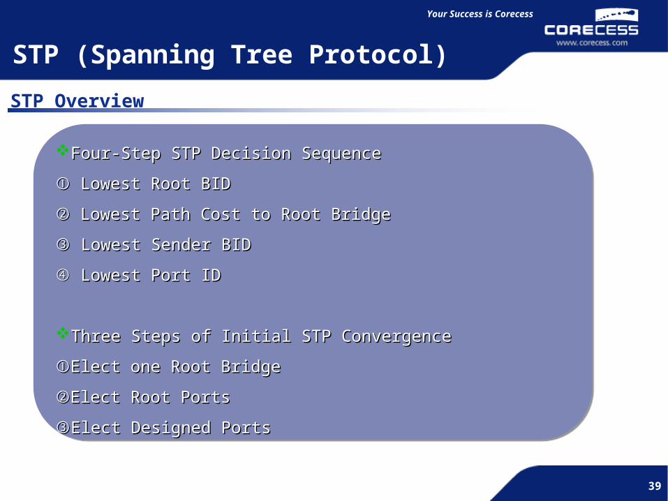
Four-Step STP Decision SequenceFour-Step STP Decision Sequence
① ① Lowest Root BIDLowest Root BID
② ② Lowest Path Cost to Root BridgeLowest Path Cost to Root Bridge
③ ③ Lowest Sender BIDLowest Sender BID
④④ Lowest Port IDLowest Port ID
Three Steps of Initial STP ConvergenceThree Steps of Initial STP Convergence
①①Elect one Root BridgeElect one Root Bridge
②②Elect Root PortsElect Root Ports
③③Elect Designed PortsElect Designed Ports

40
Simple and Flexible
40
Your Success is Corecess
40
STP (Spanning Tree Protocol)
STP Configuration
CCS5424 A CCS5424 B4/1
4/2
4/1
4/2Root Bridge
DP
DP
RP
AP
State Port Symbol
BlockingForwardingDesignated PortRoot PortAlternative Port
BFDPRPAP
F F
F B
41
Simple and Flexible
41
Your Success is Corecess
41
STP (Spanning Tree Protocol)
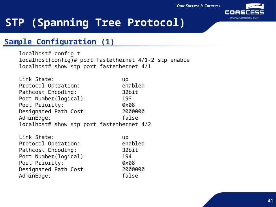
Sample Configuration (1)localhost# config tlocalhost(config)# port fastethernet 4/1-2 stp enablelocalhost# show stp port fastethernet 4/1
Link State: upProtocol Operation: enabledPathcost Encoding: 32bitPort Number(logical): 193Port Priority: 0x08Designated Path Cost: 2000000AdminEdge: falselocalhost# show stp port fastethernet 4/2
Link State: upProtocol Operation: enabledPathcost Encoding: 32bitPort Number(logical): 194Port Priority: 0x08Designated Path Cost: 2000000AdminEdge: false

42
Simple and Flexible
42
Your Success is Corecess
42
Specifying Max # of Mac address
Overview
Purpose of this study
Confirm the limit the number of MAC address in each Port Prevent illegal shared hub subscribers
Procedure of Configuration
Set to link the various PCs to an HUB
Confirm the number of PCs can able to access per port.
CCS5424CCS5424
HUBHUB
Subscriber 3Subscriber 3
Subscriber 2Subscriber 2
Subscriber 1Subscriber 1
Permit 2 PCs to port 5/1 Permit 2 PCs to port 5/1
43
Simple and Flexible
43
Your Success is Corecess
43
Specifying Max # of Mac address
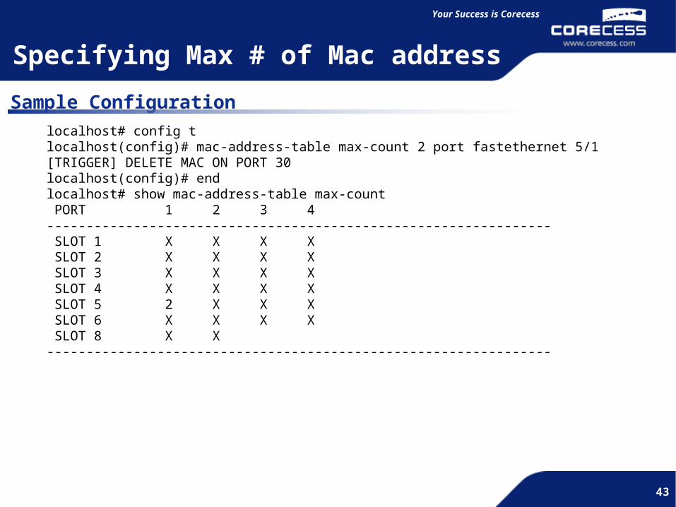
Sample Configurationlocalhost# config tlocalhost(config)# mac-address-table max-count 2 port fastethernet 5/1[TRIGGER] DELETE MAC ON PORT 30localhost(config)# endlocalhost# show mac-address-table max-count PORT 1 2 3 4---------------------------------------------------------------- SLOT 1 X X X X SLOT 2 X X X X SLOT 3 X X X X SLOT 4 X X X X SLOT 5 2 X X X SLOT 6 X X X X SLOT 8 X X----------------------------------------------------------------

44
Simple and Flexible
44
Simple and Flexible
III. Routing Protocol Configuration
Static RIPOSPF

45
Simple and Flexible
45
Your Success is Corecess
45
Routing is …..
Routing is the process of forwarding an item from one location to another.
Routers forward traffic to a logical destination in a computer network.
Routers must learn destinations that are not directly connected.
Routers need following information to route:
Destination addresses
Sources it can learn from
Possible routes
Best route
Maintain and verify routing information
172.16.1.0/24192.168.1.0/24
R1
Routing Overview
R2
R1
R3 R4
R5
46
Simple and Flexible
46
Your Success is Corecess
46
Types of Routing
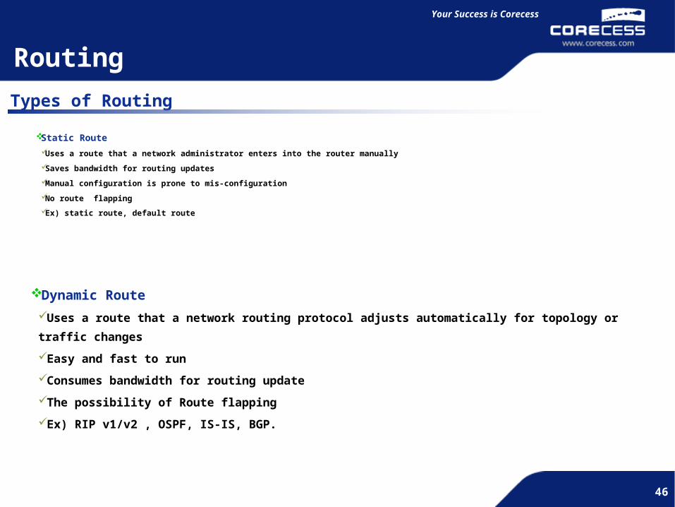
Static Route
Uses a route that a network administrator enters into the router manually
Saves bandwidth for routing updates
Manual configuration is prone to mis-configuration
No route flapping
Ex) static route, default route
Dynamic Route
Uses a route that a network routing protocol adjusts automatically for topology or traffic changes
Easy and fast to run
Consumes bandwidth for routing update
The possibility of Route flapping
Ex) RIP v1/v2 , OSPF, IS-IS, BGP.
Routing

47
Simple and Flexible
47
Your Success is Corecess
47
Administrative Distance (AD)
Administrative Distance172.1
6.1
.0/2
4
OSPF AD=110
172.16.1.0/24
RIP AD=120
172.16.1.0/24
Administrative distance is a selection method among IP routing protocols to decide which
protocols is better.
The lower the administrative distance, the more trusted the learning mechanism.
I will take the route from R2 because the route
from OSPF has lower AD than that of RIP
R1
R2
R3
R4
48
Simple and Flexible
48
Your Success is Corecess
48
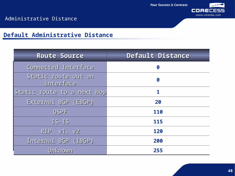
Route SourceRoute Source Default DistanceDefault Distance
Connected InterfaceConnected Interface 0
Static route out an interfaceStatic route out an interface 0
Static route to a next hopStatic route to a next hop 1
External BGP (EBGP)External BGP (EBGP) 20
OSPFOSPF 110
IS-ISIS-IS 115
RIP v1, v2RIP v1, v2 120
Internal BGP (IBGP)Internal BGP (IBGP) 200
UnknownUnknown 255
Default Administrative Distance
Administrative Distance
49
Simple and Flexible
49
Your Success is Corecess
49
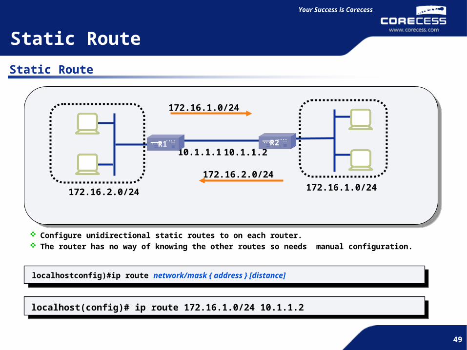
Static Route
10.1.1.2
172.16.1.0/24
10.1.1.1
Configure unidirectional static routes to on each router. The router has no way of knowing the other routes so needs manual configuration.
Static Route
172.16.2.0/24
172.16.1.0/24
172.16.2.0/24
localhost(config)# ip route 172.16.1.0/24 10.1.1.2
localhostconfig)#ip route network/mask { address } [distance]
R2R1
50
Simple and Flexible
50
Your Success is Corecess
50
Static Route
Static Route
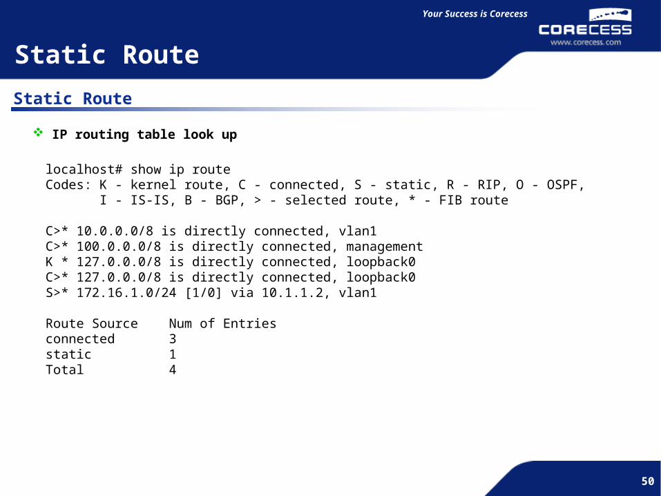
IP routing table look up
localhost# show ip routeCodes: K - kernel route, C - connected, S - static, R - RIP, O - OSPF, I - IS-IS, B - BGP, > - selected route, * - FIB route
C>* 10.0.0.0/8 is directly connected, vlan1C>* 100.0.0.0/8 is directly connected, managementK * 127.0.0.0/8 is directly connected, loopback0C>* 127.0.0.0/8 is directly connected, loopback0S>* 172.16.1.0/24 [1/0] via 10.1.1.2, vlan1
Route Source Num of Entriesconnected 3static 1Total 4

51
Simple and Flexible
51
Your Success is Corecess
51
10.1.1.2
172.16.1.0/24
(Stub Network)
10.1.1.1
Default route is useful in stub network instead of configuring all routes to get. Reduces the size of routing table. Stub network is the network which has the single exit point.
Default Route
172.16.1.0/24
Default (0.0.0.0/.0)
localhostconfig)#ip route default 10.1.1.1
localhost(config)#ip route default { address } [distance]
External Network
Default Route
R1 R2
52
Simple and Flexible
52
Your Success is Corecess
52
RIP has metric as hop-count. The hop-count increase by 1 each time the route passes through networks.
Maximum hop-count for RIP is 15. More than 16 will be unreachable.
RIP is not scalable routing protocol because of the limited hop-count.
RIP sends routing update in regular interval (Default timer is 30 seconds).
RIP V1 is classful routing protocol which means it does not advertise the subnet mask information.
RIP V2 support classless routing update and authentication.
RIP V1 uses broadcast address to update and RIP V2 uses multicast address 224.0.0.9 to update.
Use UDP port number 520
Default RIP Version for CCS5424 is version 2.
Routing Information Protocol (RIP)
RIP Overview

53
Simple and Flexible
53
Your Success is Corecess
53
2.3.0.0
router rip
network 172.16.1.0/24
network 10.1.1.0/24
router rip
network 10.1.1.0/24
network 10.1.2.0/24
2.3.0.0router rip
network 192.168.1.0/24
network 10.1.2.0/24
172.16.1.0/24A B C
192.168.1.0/24R2R1 R3
10.1.1.0/24 10.1.2.0/24
.1.1 .1.1.2 .2
Localhost(config)#router rip
localhost(config-router)# network network/mask
Routing Information Protocol (RIP)
RIP Configuration
R1 R2 R3

54
Simple and Flexible
54
Your Success is Corecess
54
OSPF (Open Shortest Path First)
OSPF is a open hierarchical routing protocol using areas.
Supports VLSM (Variable Length Subnet Mask) and CIDR(Classless InterDomain Routing).
OSPF uses IP multicast(224.0.0.5 and 224.0.0.6) to send link-state updates.
Processes updates efficiently, that updates are only sent in case routing changes occur instead of
periodically.
OSPF allows for a logical definition of networks where routers can be divided into areas.
Areas will limit the explosion of link state updates over the whole network.
OSPF allows for routing authentication by using different methods(clear-text and MD5) of password
authentication.
OSPF uses bandwidth to calculate the best route called cost.
Uses hello messages to set up neighbor and acts as keepalive.
All area should have connection to backbone area which is area 0.
OSPF Overview
55
Simple and Flexible
55
Your Success is Corecess
55
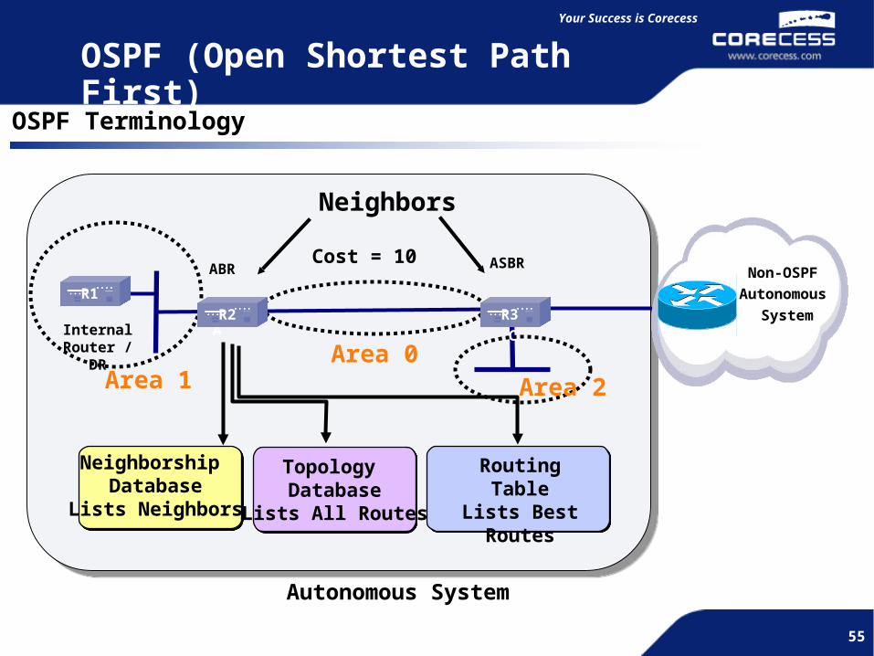
Autonomous System
RoutingTable
Lists Best Routes
Topology Database
Lists All Routes
Neighborship Database
Lists Neighbors
Cost = 10
Neighbors
Area 1Area 0
A C
Area 2
ABR ASBRNon-OSPF
Autonomous
SystemInternal
Router / DR
OSPF Terminology
OSPF (Open Shortest Path First)
R1R2 R3

56
Simple and Flexible
56
Your Success is Corecess
56
OSPF Configuration
2.3.0.0
router ospf
network 172.16.1.0/24 area
1
network 10.1.1.0/24 area 0
router ospf
network 10.1.1.0/24 area 0
network 10.1.2.0/24 area 0
2.3.0.0router ospf
network 192.168.1.0/24 area 2
network 10.1.2.0/24 area 0
172.16.1.0/24A B C
192.168.1.0/2410.1.1.0/24 10.1.2.0/24
.1.1 .1.1.2 .2
CC6800[ACT](config)#router ospf
CC6800[ACT](config-router)# network network/mask area area-id
Area 2Area 0Area 1
OSPF (Open Shortest Path First)
R1 R2 R3

57
Simple and Flexible
57
Your Success is Corecess
57
R2# sh ip ospf neighbor
Neighbor ID Pri State Dead Time Address Interface 172.16.1.1 1 Full/DR 00:00:33 10.1.1.1 4/1 192.168.1.1 1 Full/DR 00:00:34 10.1.2.2 4/2
R2# sh ip route
C>* 10.1.1.0/24 is directly connected, 4/1
C>* 10.1.2.0/24 is directly connected, 4/2
O>* 172.16.1.0/24 [110/1] via 10.1.1.1, 4/1, 00:01:01
O>* 192.168.1.0/24 [110/1] via 10.1.2.2, 4/2, 00:01:01
OSPF (Open Shortest Path First)
Verify OSPF

58
Simple and Flexible
58
Your Success is Corecess
58
2.3.0.0
172.16.1.0/24A B C
192.168.1.0/2410.1.1.0/24 10.1.2.0/24
.1.1 .1.1.2.2
Area 2Area 0Area 1
100.1.1.0/24
100.1.1.0/24
External Network
192.168.1.0/24
router ospfnetwork 172.16.1.0/24 area 1network 10.1.1.0/24 area 1area 1 stub
router ospfnetwork 10.1.1.0/24 area 1network 10.1.2.0/24 area 0area 1 stub
router ospfnetwork 192.168.1.0/24 area 2network 10.1.2.0/24 area 0
The ABR on stub area drops LSA type 5 which is learned from non-ospf domain and advertises default route.
ABR and internal routers must be configured to set stub area.
An ASBR cannot be internal to stub area.
The backbone Area can not be stub area.
On the stub area, Virtual links are not allowed
192.168.1.0/24
Default (0.0.0.0/0)
OSPF (Open Shortest Path First)
Stub Area
R1 R2 R3

59
Simple and Flexible
59
Your Success is Corecess
59
R1# sh ip route
C>* 10.1.1.0/24 is directly connected, 4/1
C>* 172.16.1.0/24 is directly connected, vlan1
O>* 10.1.2.0/24 [120/1] via 10.1.1.2, 4/1, 00:00:10
O>* 192.168.1.0/24 [120/1] via 10.1.1.2, 4/1, 00:00:05
O>* default [120/1] via 10.1.1.2, 4/1, 00:00:05
R2# sh ip route
C>* 10.1.1.0/24 is directly connected, 4/1
C>* 10.1.2.0/24 is directly connected, 4/2
O>* 192.168.1.0/24 [120/1] via 10.1.2.1, 4/2, 00:00:10
O>* 172.16.1.0/24 [120/1] via 10.1.1.2, 4/1, 00:0:10
O>* 100.1.1.0/24 [120/1] via 10.1.1.2, 4/1, 00:00:05
R3# sh ip route
C>* 10.1.2.0/24 is directly connected, 4/1
C>* 10.1.3.0/24 is directly connected, 4/2
C>* 192.168.1.0/24 is directly connected, vlan1
O>* 10.1.1.0/24 [120/1] via 10.1.2.1, 4/1, 00:00:10
O>* 172.16.1.0/24[120/1] via 10.1.2.1, 4/1, 00:00:10
O>* 100.1.1.0/24 [120/1] via 10.1.3.2, 4/2, 00:00:05
Verify Stub Area
OSPF (Open Shortest Path First)

60
Simple and Flexible
60
Your Success is Corecess
60
Totally Stub Area
2.3.0.0
172.16.1.0/24A B C
192.168.1.0/2410.1.1.0/24 10.1.2.0/24
.1.1 .1.1.2 .2
Area 2Area 0Area 1
100.1.1.0/24Default (0.0.0.0/0)
100.1.1.0/24
External Network
192.168.1.0/24
router ospfnetwork 172.16.1.0/24 area 1network 10.1.1.0/24 area 1area 1 stub
router ospfnetwork 10.1.1.0/24 area 1network 10.1.2.0/24 area 0area 1 stub no-summary
router ospfnetwork 192.168.1.0/24 area 2network 10.1.2.0/24 area 0
ABRs on totally stub area drop LSA type 3/4/5 and advertise default route.
ABR must be configured to set area totally stub area and internal routers are optional.
An ASBR cannot be internal to totally stub.
Area is not the backbone Area 0.
Virtual links are not allowed.
OSPF (Open Shortest Path First)
R1 R2 R3

61
Simple and Flexible
61
Your Success is Corecess
61
R1#sh ip route
C>* 10.1.1.0/24 is directly connected, 4/1
C>* 172.16.1.0/24 is directly connected, vlan1
O>* 10.1.2.0/24 [120/1] via 10.1.1.2, 4/1, 00:00:10
O>* default [120/1] via 10.1.1.2, 4/1, 00:00:05
R2# sh ip route
C>* 10.1.1.0/24 is directly connected, 4/1
C>* 10.1.2.0/24 is directly connected, 4/1
O>* 192.168.1.0/24 [120/1] via 10.1.2.1, 4/1, 00:00:10
O>* 172.16.1.0/24 [120/1] via 10.1.1.2, 4/1, 00:0:10
O>* 100.1.1.0/24 [120/1] via 10.1.1.2, 4/1, 00:00:05
R3# sh ip route
C>* 10.1.2.0/24 is directly connected, 4/1
C>* 10.1.3.0/24 is directly connected, 4/2
C>* 192.168.1.0/24 is directly connected, vlan1
O>* 10.1.1.0/24 [120/1] via 10.1.2.1, 4/1, 00:00:10
O>* 172.16.1.0/24[120/1] via 10.1.2.1, 4/1, 00:00:10
O>* 100.1.1.0/24 [120/1] via 10.1.3.2, 4/2, 00:00:05
OSPF (Open Shortest Path First)
Verify Totally Stub Area
62
Simple and Flexible
62
Your Success is Corecess
62
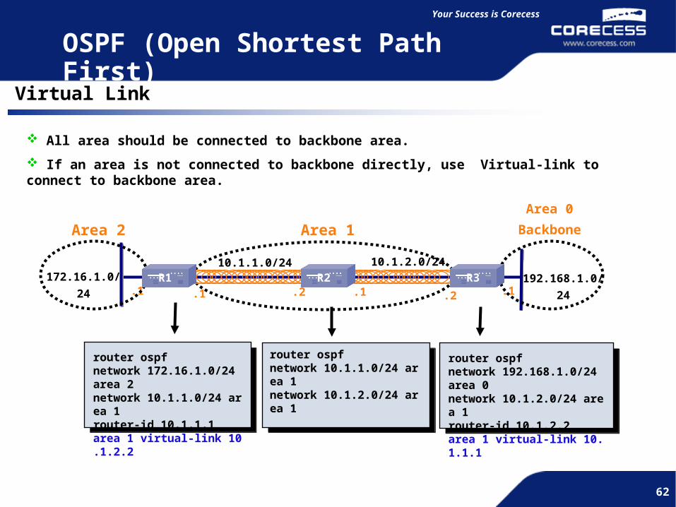
Virtual Link
2.3.0.0
172.16.1.0/24A B C
192.168.1.0/24
10.1.1.0/24 10.1.2.0/24
.1.1 .1.1.2 .2
router ospfnetwork 172.16.1.0/24 area 2network 10.1.1.0/24 area 1router-id 10.1.1.1area 1 virtual-link 10.1.2.2
router ospfnetwork 10.1.1.0/24 area 1network 10.1.2.0/24 area 1
router ospfnetwork 192.168.1.0/24 area 0network 10.1.2.0/24 area 1router-id 10.1.2.2area 1 virtual-link 10.1.1.1
All area should be connected to backbone area.
If an area is not connected to backbone directly, use Virtual-link to connect to backbone area.
Area 2 Area 1
Area 0
Backbone
OSPF (Open Shortest Path First)
R1 R2 R3
63
Simple and Flexible
63
Your Success is Corecess
63
2.3.0.0
172.16.1.0/24
192.168.1.0/24
192.168.2.0/24
192.168.3.0/24
192.168.4.0/24
192.168.5.0/24
10.1.1.0/24 10.1.2.0/24
.1.1 .1.1.2 .2
Area 2Area 0Area 1
192.168.0.0/21
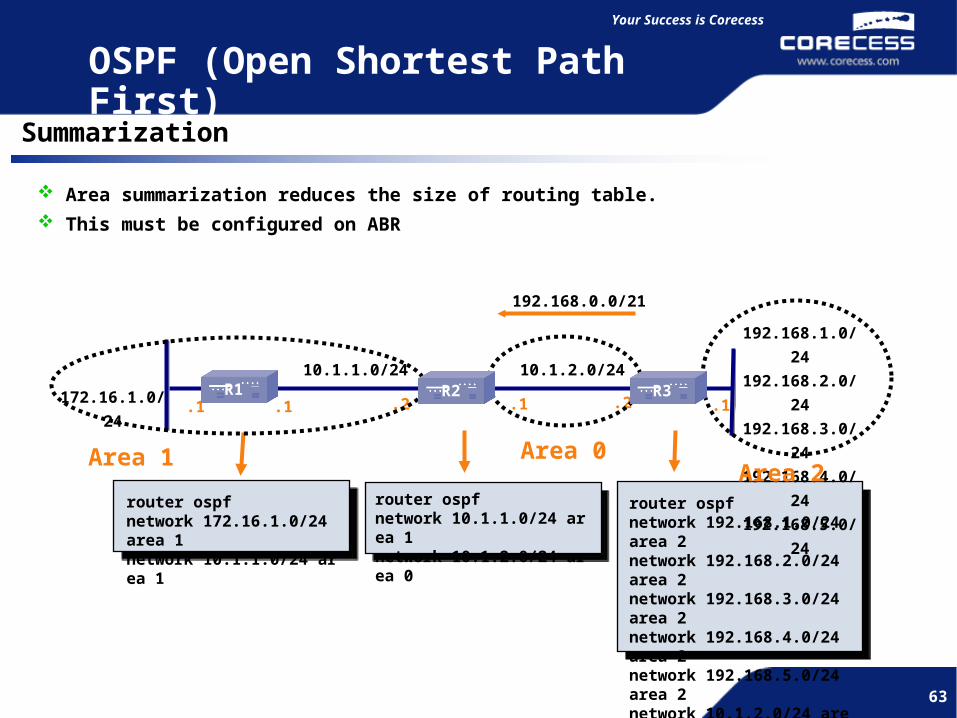
router ospfnetwork 172.16.1.0/24 area 1network 10.1.1.0/24 area 1
router ospfnetwork 10.1.1.0/24 area 1network 10.1.2.0/24 area 0
router ospfnetwork 192.168.1.0/24 area 2network 192.168.2.0/24 area 2network 192.168.3.0/24 area 2network 192.168.4.0/24 area 2network 192.168.5.0/24 area 2network 10.1.2.0/24 area 0area 2 range 192.168.0.0/21
Area summarization reduces the size of routing table.
This must be configured on ABR
OSPF (Open Shortest Path First)
Summarization
R1 R2 R3

64
Simple and Flexible
64
Simple and Flexible
IV. Multicast Protocol Configuration
PIM-SM

65
Simple and Flexible
65
Your Success is Corecess
65
PIM – SM OverviewOverview
Protocol independent (uses unicast route table for RPF check)
No separate multicast routing protocol
Explicit Join Model (Transmit Multicast Traffic only if there is PIM Join Request )
PIM-SM is efficient because it does not send useless Prune Message from Root.
PIM-SM is Single, Unidirectional shared tree structure.
ROOT of PIM-SM is called RP (Rendezvous Point), and created Shared Tree is called
RP (Rendezvous Point) Tree = RPT.

66
Simple and Flexible
66
Your Success is Corecess
66
PIM - SMShared Tree Joins
A B RP D
C E
Receiver 1 (Group G)
1
3
2
4
New Receiver 2 (Group G)
5
67
8
PIM-SM is Single, Unidirectional shared tree structure. ROOT of PIM-SM is called RP (Rendezvous Point), and created Shared Tree is called RP (Rendezvous Point) Tree = RPT.
Receiver Join Router C creates Routing Table for this multicast group (*,G) places the Ethernet interface in the outgoing interface list of the (*,G) entry. Router C Join RP of Shared Tree RP creates (*,G) Routing Table adds the link to
Router C to the outgoing interface list for (*,G) Router E (*,G) creates Routing Table when Receiver 2 Join as (*,G) Register
Outgoing Interface for (*,G) Router E Joins Router C for (*,G) Router C add Router E to Outgoing Interface after checking that (*,G) is exists at Shared Tree.
1
32
45
6
7
67
Simple and Flexible
67
Your Success is Corecess
67
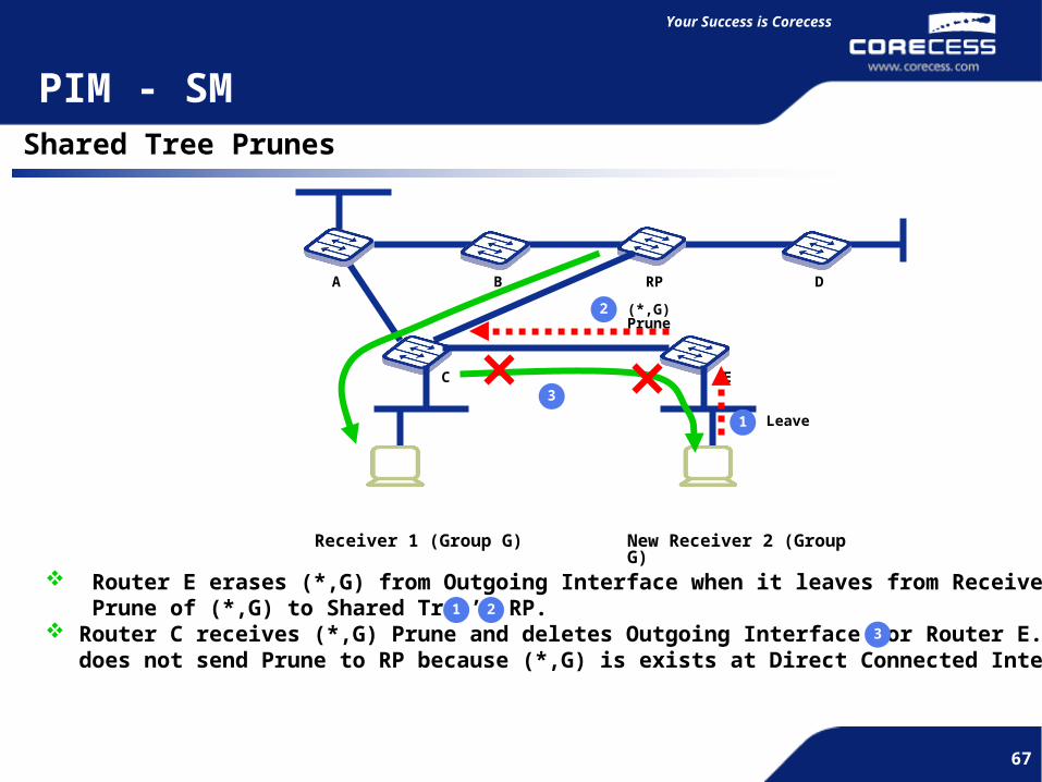
PIM - SMShared Tree Prunes
A B RP D
C E
Receiver 1 (Group G)
1
New Receiver 2 (Group G)
2
Leave
(*,G) Prune
3
Router E erases (*,G) from Outgoing Interface when it leaves from Receiver 2. Transmit Prune of (*,G) to Shared Tree’s RP.
Router C receives (*,G) Prune and deletes Outgoing Interface for Router E. Router C does not send Prune to RP because (*,G) is exists at Direct Connected Interface’s below.
1 2
3
68
Simple and Flexible
68
Your Success is Corecess
68
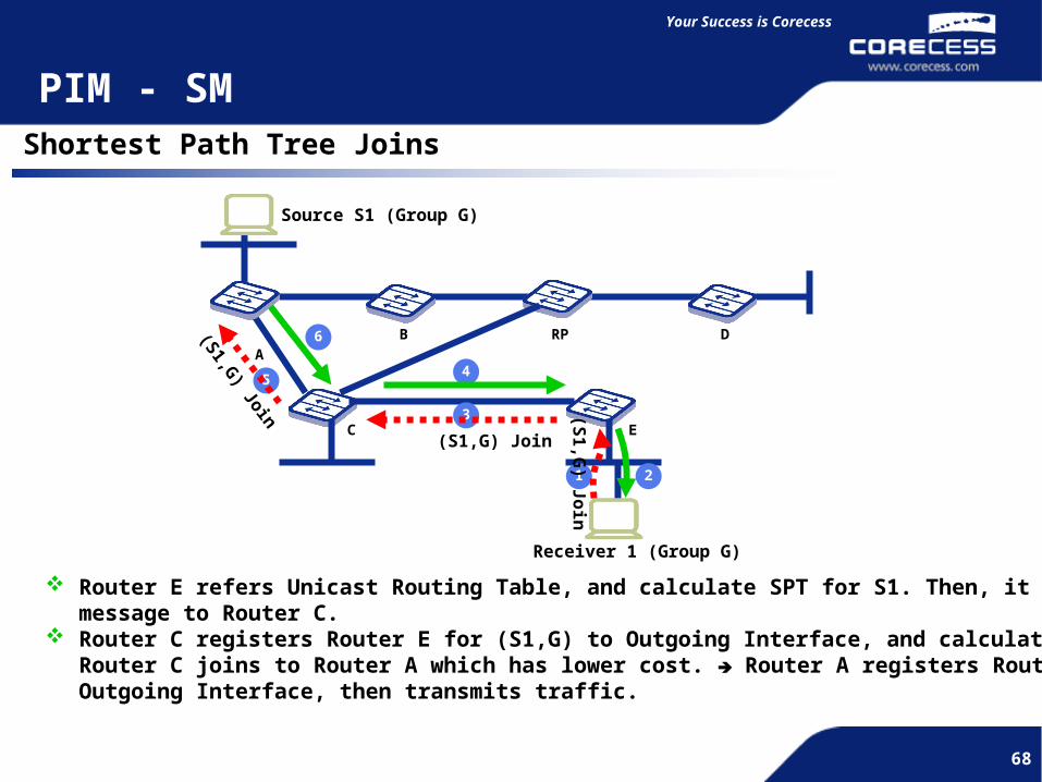
PIM - SMShortest Path Tree Joins
A
B RP D
C E
Receiver 1 (Group G)
1
3
2
45
6
Source S1 (Group G)
Router E refers Unicast Routing Table, and calculate SPT for S1. Then, it sends Join message to Router C.
Router C registers Router E for (S1,G) to Outgoing Interface, and calculate RPF. And, Router C joins to Router A which has lower cost. Router A registers Router C at Outgoing Interface, then transmits traffic.
(S1,G) Join
(S1,G) Join
(S1
,G) J
oin

69
Simple and Flexible
69
Your Success is Corecess
69
PIM - SMPIM Join/Prune Message
Join / Prune message has Multicast Source Address, Multicast Group Address, and Flags information.
PIM Join/ Prune message 1. Multicast source address : Multicast Source IP address 2. Multicast group address : Multicast Address for Join / Prune 3. WC bit (Wildcard flag) : Join / Prune Shared Tree (*.G) Entry 4. RP bit(RP Tree flag) : The information is forwarding to upper Shared Tree. Ex.) If PIM Join information of Join/ Prune message has flowing entry, Source address = 100.1.1.1Source address = 100.1.1.1 Group address = 224.1.1.1Group address = 224.1.1.1 Flags =WC, RPFlags =WC, RP WC and RP bit is set to (*,G) and Multicast Groups of 224.1.1.1 is the address for
Join. And, it forward to 100.1.1.1 which is RP.
And, if Prune entry is as follows, Source address = 200.1.1.1Source address = 200.1.1.1 Group address = 224.100.100.100Group address = 224.100.100.100 Flags = noneFlags = none (S,G) which Source is 200.1.1.1 and Multicast Group of 224.100.100.100 is for
Pruning.
70
Simple and Flexible
70
Your Success is Corecess
70
PIM - SMPIM-SM State-Refresh
If Up Stream Router does not process Prune Message because of congestion or some other reasons, the Router erases Multicast Routing Table of (*,G) and (S,G) after Life time (3 min.). Therefore, after 3 minuets Time out, Down Stream Router forwards PIM Join/Prune message to Up Stream Neighbor in every 1 minuet to prevent Entry Delete.
The Router which received PIM Join/ Prune message, refreshes Multicast Routing Table Entry, and resets Expiration Timer (3 minuets).

71
Simple and Flexible
71
Your Success is Corecess
71
PIM - SMConfiguration
R2 R1Media Server10.10.10.10
User100.1.1.10
f4/1 vlan id 210.10.10.1/24
f4/2 vlan id 3 172.1.1.1/24
f4/1 vlan id 2172.1.1.2/24
f4/2 vlan id 3100.1.1.1/24
OSPF area 0

72
Simple and Flexible
72
Your Success is Corecess
72
PIM - SMSample Configuration
R1# config tR1(config)# vlan id 2 port fastethernet 4/1[CRCS]sys_mac_vlan : mac addr=00:90:a3:cd:06:d2R1(config)# vlan id 3 port fastethernet 4/2[CRCS]sys_mac_vlan : mac addr=00:90:a3:cd:06:d3R1(config)# int vlan id 2[CRCS]vlan2 : mac addr=00:90:a3:cd:06:d2R1(config-if)# ip address 10.10.10.1/24R1(config-if)# ip pim-smR1(config-if)# exitR1(config)# int vlan id 3[CRCS]vlan3 : mac addr=00:90:a3:cd:06:d3R1(config-if)# ip address 172.1.1.1/24R1(config-if)# ip pim-smR1(config-if)# exitR1(config)# ip pim-sm static-rp 10.10.10.1R1(config)# router ospfR1(config-router)# network 10.10.10.0/24 area 0R1(config-router)# network 172.1.1.0/24 area 0R1(config-router)# end
Define Static RP (Rendezvous Point)
73
Simple and Flexible
73
Your Success is Corecess
73
PIM - SMSample Configuration
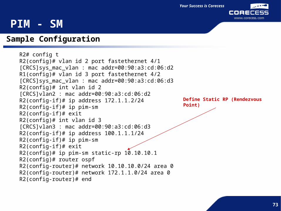
R2# config tR2(config)# vlan id 2 port fastethernet 4/1[CRCS]sys_mac_vlan : mac addr=00:90:a3:cd:06:d2R1(config)# vlan id 3 port fastethernet 4/2[CRCS]sys_mac_vlan : mac addr=00:90:a3:cd:06:d3R2(config)# int vlan id 2[CRCS]vlan2 : mac addr=00:90:a3:cd:06:d2R2(config-if)# ip address 172.1.1.2/24R2(config-if)# ip pim-smR2(config-if)# exitR2(config)# int vlan id 3[CRCS]vlan3 : mac addr=00:90:a3:cd:06:d3R2(config-if)# ip address 100.1.1.1/24R2(config-if)# ip pim-smR2(config-if)# exitR2(config)# ip pim-sm static-rp 10.10.10.1R2(config)# router ospfR2(config-router)# network 10.10.10.0/24 area 0R2(config-router)# network 172.1.1.0/24 area 0R2(config-router)# end
Define Static RP (Rendezvous Point)
74
Simple and Flexible
74
Your Success is Corecess
74
PIM - SMVerify PIM Routing Entry
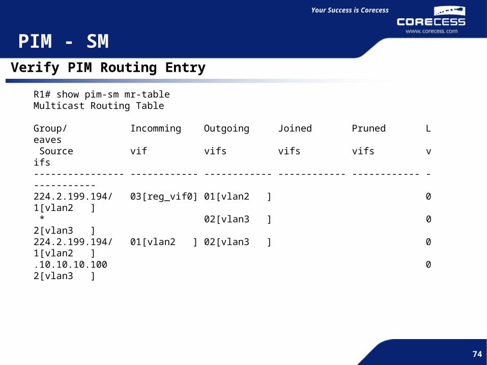
R1# show pim-sm mr-tableMulticast Routing Table
Group/ Incomming Outgoing Joined Pruned Leaves Source vif vifs vifs vifs vifs---------------- ------------ ------------ ------------ ------------ ------------224.2.199.194/ 03[reg_vif0] 01[vlan2 ] 01[vlan2 ] * 02[vlan3 ] 02[vlan3 ]224.2.199.194/ 01[vlan2 ] 02[vlan3 ] 01[vlan2 ].10.10.10.100 02[vlan3 ]


